WO2013080974A1 - 衝撃吸収部材 - Google Patents
衝撃吸収部材 Download PDFInfo
- Publication number
- WO2013080974A1 WO2013080974A1 PCT/JP2012/080632 JP2012080632W WO2013080974A1 WO 2013080974 A1 WO2013080974 A1 WO 2013080974A1 JP 2012080632 W JP2012080632 W JP 2012080632W WO 2013080974 A1 WO2013080974 A1 WO 2013080974A1
- Authority
- WO
- WIPO (PCT)
- Prior art keywords
- absorbing member
- carbon fiber
- thermoplastic resin
- abundance
- mass
- Prior art date
- Legal status (The legal status is an assumption and is not a legal conclusion. Google has not performed a legal analysis and makes no representation as to the accuracy of the status listed.)
- Ceased
Links
Images







Classifications
-
- F—MECHANICAL ENGINEERING; LIGHTING; HEATING; WEAPONS; BLASTING
- F16—ENGINEERING ELEMENTS AND UNITS; GENERAL MEASURES FOR PRODUCING AND MAINTAINING EFFECTIVE FUNCTIONING OF MACHINES OR INSTALLATIONS; THERMAL INSULATION IN GENERAL
- F16F—SPRINGS; SHOCK-ABSORBERS; MEANS FOR DAMPING VIBRATION
- F16F7/00—Vibration-dampers; Shock-absorbers
- F16F7/12—Vibration-dampers; Shock-absorbers using plastic deformation of members
-
- B—PERFORMING OPERATIONS; TRANSPORTING
- B29—WORKING OF PLASTICS; WORKING OF SUBSTANCES IN A PLASTIC STATE IN GENERAL
- B29C—SHAPING OR JOINING OF PLASTICS; SHAPING OF MATERIAL IN A PLASTIC STATE, NOT OTHERWISE PROVIDED FOR; AFTER-TREATMENT OF THE SHAPED PRODUCTS, e.g. REPAIRING
- B29C70/00—Shaping composites, i.e. plastics material comprising reinforcements, fillers or preformed parts, e.g. inserts
- B29C70/04—Shaping composites, i.e. plastics material comprising reinforcements, fillers or preformed parts, e.g. inserts comprising reinforcements only, e.g. self-reinforcing plastics
- B29C70/28—Shaping operations therefor
- B29C70/40—Shaping or impregnating by compression not applied
- B29C70/42—Shaping or impregnating by compression not applied for producing articles of definite length, i.e. discrete articles
- B29C70/46—Shaping or impregnating by compression not applied for producing articles of definite length, i.e. discrete articles using matched moulds, e.g. for deforming sheet moulding compounds [SMC] or prepregs
- B29C70/462—Moulding structures having an axis of symmetry or at least one channel, e.g. tubular structures, frames
-
- C—CHEMISTRY; METALLURGY
- C08—ORGANIC MACROMOLECULAR COMPOUNDS; THEIR PREPARATION OR CHEMICAL WORKING-UP; COMPOSITIONS BASED THEREON
- C08J—WORKING-UP; GENERAL PROCESSES OF COMPOUNDING; AFTER-TREATMENT NOT COVERED BY SUBCLASSES C08B, C08C, C08F, C08G or C08H
- C08J5/00—Manufacture of articles or shaped materials containing macromolecular substances
- C08J5/04—Reinforcing macromolecular compounds with loose or coherent fibrous material
- C08J5/0405—Reinforcing macromolecular compounds with loose or coherent fibrous material with inorganic fibres
- C08J5/042—Reinforcing macromolecular compounds with loose or coherent fibrous material with inorganic fibres with carbon fibres
-
- C—CHEMISTRY; METALLURGY
- C08—ORGANIC MACROMOLECULAR COMPOUNDS; THEIR PREPARATION OR CHEMICAL WORKING-UP; COMPOSITIONS BASED THEREON
- C08K—Use of inorganic or non-macromolecular organic substances as compounding ingredients
- C08K7/00—Use of ingredients characterised by shape
- C08K7/02—Fibres or whiskers
- C08K7/04—Fibres or whiskers inorganic
- C08K7/06—Elements
-
- F—MECHANICAL ENGINEERING; LIGHTING; HEATING; WEAPONS; BLASTING
- F16—ENGINEERING ELEMENTS AND UNITS; GENERAL MEASURES FOR PRODUCING AND MAINTAINING EFFECTIVE FUNCTIONING OF MACHINES OR INSTALLATIONS; THERMAL INSULATION IN GENERAL
- F16F—SPRINGS; SHOCK-ABSORBERS; MEANS FOR DAMPING VIBRATION
- F16F7/00—Vibration-dampers; Shock-absorbers
- F16F7/12—Vibration-dampers; Shock-absorbers using plastic deformation of members
- F16F7/124—Vibration-dampers; Shock-absorbers using plastic deformation of members characterised by their special construction from fibre-reinforced plastics
-
- C—CHEMISTRY; METALLURGY
- C08—ORGANIC MACROMOLECULAR COMPOUNDS; THEIR PREPARATION OR CHEMICAL WORKING-UP; COMPOSITIONS BASED THEREON
- C08K—Use of inorganic or non-macromolecular organic substances as compounding ingredients
- C08K2201/00—Specific properties of additives
- C08K2201/002—Physical properties
- C08K2201/004—Additives being defined by their length
-
- Y—GENERAL TAGGING OF NEW TECHNOLOGICAL DEVELOPMENTS; GENERAL TAGGING OF CROSS-SECTIONAL TECHNOLOGIES SPANNING OVER SEVERAL SECTIONS OF THE IPC; TECHNICAL SUBJECTS COVERED BY FORMER USPC CROSS-REFERENCE ART COLLECTIONS [XRACs] AND DIGESTS
- Y10—TECHNICAL SUBJECTS COVERED BY FORMER USPC
- Y10T—TECHNICAL SUBJECTS COVERED BY FORMER US CLASSIFICATION
- Y10T428/00—Stock material or miscellaneous articles
- Y10T428/24—Structurally defined web or sheet [e.g., overall dimension, etc.]
- Y10T428/24149—Honeycomb-like
Definitions
- the present invention has a bottom portion and a raised portion provided on the bottom portion, and at least one of the bottom portion and the raised portion is made of a carbon fiber reinforced composite material containing a thermoplastic resin, and the other is thermoplastic. Further, the present invention relates to a lightweight impact absorbing member that may be made of resin, and further relates to an impact absorbing member that is preferably used for a moving body such as an aircraft, an automobile, a train, and a two-wheeled vehicle. The present invention also relates to a method for manufacturing the impact absorbing member.
- Patent Document 1 discloses an energy absorbing member made of a fiber-reinforced composite material in which long fibers are cross-laminated to form a plurality of layers.
- the impact energy can be absorbed well, but the degree of freedom of the shape is low, and there are restrictions on the parts that can be used.
- the molding becomes complicated, and the manufacturing tact and manufacturing cost are high.
- Patent Document 2 discloses an energy absorbing member using a fiber reinforced resin mixed with short fibers.
- the fiber reinforced resin mixed with short fibers has a low energy absorption amount per mass of the member, the mass of the member becomes heavy when absorbing large energy.
- An object of the present invention is to provide an impact absorbing member that is lightweight, has a high degree of freedom in shape, and can efficiently absorb impact energy.
- the present invention comprises a bottom surface portion and a raised portion provided on the bottom surface portion, and at least one of the bottom surface portion and the raised portion is made of a carbon fiber reinforced composite material containing a thermoplastic resin, and the other is a thermoplastic material.
- the impact absorbing member may be made of a resin, and the amount of the thermoplastic resin in the impact absorbing member is 30 to 1000 parts by mass with respect to 100 parts by mass of the carbon fiber, and the average fiber of the carbon fiber
- An impact-absorbing member having a length of 3 to 100 mm and a method for producing the same.
- an impact-absorbing member that is lightweight, has a high degree of freedom in shape, and can efficiently absorb impact energy. Furthermore, the manufacturing method which can manufacture efficiently the impact-absorbing member which is lightweight, has high freedom degree of shape, and can absorb impact energy efficiently can be provided.
- FIG. 1 is a perspective view of a first embodiment of the present invention (an impact absorbing member whose upright portion has a cross-column shape).
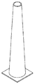
- the perspective view of 2nd Embodiment (the impact-absorbing member whose upright part is cylindrical pillar shape) of this invention.
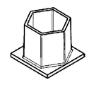
- the perspective view of 3rd Embodiment (The impact-absorbing member whose standing part is a hollow polygonal column shape (hollow hexagon shape)) of this invention.
- the perspective view of 4th Embodiment the impact-absorbing member whose upright part is a honeycomb pillar shape) of this invention.
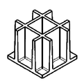
- the perspective view of 5th Embodiment (the impact-absorbing member whose cross section is a grid
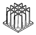
- the perspective view of 6th Embodiment (the impact-absorbing member in which an upright part is a column shape of a triangular lattice-like cross section) of this invention.
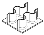
- the perspective view of 7th Embodiment (shock absorbing member whose upright part is corrugated wall shape) of this invention.
- the perspective view of 8th Embodiment (the impact-absorbing member whose standing part is a grid
- the perspective view of 9th Embodiment (The impact-absorbing member whose standing part is a honeycomb pillar shape) of this invention.
- the perspective view of 10th Embodiment (the impact-absorbing member whose upright part is a cross-column shape) of this invention.
- the perspective view of 11th Embodiment (the impact-absorbing member whose upright part is a hollow truncated cone shape) of this invention.
- a perspective view of a twelfth embodiment of the present invention (an impact absorbing member having an upright portion that is a cylindrical columnar shape whose thickness changes stepwise and whose upper portion is thicker than the lower portion of the upright portion).
- a perspective view of a thirteenth embodiment of the present invention (an impact absorbing member having a cylindrical column shape in which an upright portion is gradually changing in thickness and whose lower portion is thicker than the upper portion of the upright portion).
- a perspective view of a fourteenth embodiment of the present invention an impact-absorbing member in which an upright portion is a columnar cross section in a cross section and further has a cylindrical upright portion in a central portion of the lattice shape).
- the perspective view of 15th Embodiment The impact-absorbing member whose upright part is a hollow polygonal column shape (hollow pentagon shape)) of this invention.
- the shock absorbing member of the present invention comprises a bottom surface portion and an upright portion provided on the bottom surface portion, and at least one of the bottom surface portion and the upright portion is composed of a carbon fiber reinforced composite material containing a thermoplastic resin, and the other Is an impact-absorbing member that may be made of a thermoplastic resin, and the amount of the thermoplastic resin in the impact-absorbing member is 30 to 1000 parts by mass with respect to 100 parts by mass of the carbon fiber, and the carbon fiber The average fiber length is 3 to 100 mm.
- the impact-absorbing member of this invention can also be called the use of the thing containing the molded object of a carbon fiber reinforced composite material, or a molded object.
- the impact absorbing member of the present invention preferably has a bottom surface portion and an upright portion extending in a direction perpendicular to the bottom surface portion. If the upright portion is perpendicular to the bottom surface portion, it does not have to be strictly perpendicular, and an arbitrary angle or an angle for securing the draft angle of the mold can be taken to the extent that the intention of the present invention is not impaired. Is possible.
- the angle at which the bottom portion and the raised portion are woven is preferably 30 to 90 degrees, and more preferably 40 to 90 degrees. Arbitrary chamfering and curvature can be added between the bottom surface portion and the upright portion to such an extent that the intention of the present invention is not impaired.
- the upright portion may be molded integrally with the bottom surface portion.
- the upright portion is molded with a carbon fiber composite material, the bottom surface portion is molded with a thermoplastic resin, etc.
- the bottom surface portion refers to a portion that is substantially planar and serves as the foundation of the upright portion.
- the bottom surface portion does not have to be completely planar, and may have partial unevenness and beads.
- the height and width of the unevenness and the bead are not particularly limited, but the height is preferably 0.5 to 2 times the thickness of the base bottom portion plate.
- the impact absorbing member (molded body) may be simultaneously formed with a shear or the like in the mold, or may be opened by drilling, punching, cutting or the like as post-processing.
- the thickness of the bottom portion is not particularly limited, but is preferably 0.2 to 5 mm, and more preferably 1 to 3 mm.
- the thickness of the bottom portion does not need to be uniform, and can be locally increased or decreased. In this case, there is no particular limitation on the increase / decrease width of the plate thickness, but it is preferably 30 to 300%, more preferably 50 to 200% of the base bottom plate thickness.
- the plate thickness can be changed stepwise, and can be continuously changed with a taper or a curvature, but it is preferably changed continuously from the viewpoint of avoiding stress concentration.
- the upright portion means a portion extending in the vertical direction on the same side with respect to the above-described bottom surface portion, and ribs and bosses are given as examples.
- the height of the upright portion is not particularly limited, but is preferably 1 to 300 mm, more preferably 5 to 100 mm.
- the height of the upright portion does not need to be uniform and can be increased or decreased locally.
- There is no particular limitation on the increase / decrease width of the upright height preferably 10 to 90% of the maximum height, and more preferably 20 to 80%.
- the height of the upright portion is preferably 2 times or more, and more preferably 5 times or more the plate thickness of the bottom surface portion.
- the height of the upright part there is no upper limit on the height of the upright part, but it is sufficient for most applications if it is 1500 times or less than the thickness of the bottom part, and even if it is 100 times or less, it is sufficient for many applications. It is.
- board thickness of an upright part and it may be the same as a bottom face part, and may differ. Since the upright portion is often required to have a more complicated shape than the bottom surface portion, the plate thickness of the upright portion is preferably 0.2 to 100 mm, and more preferably 1 to 50 mm. The plate thickness of the upright portion does not need to be uniform, and can be locally increased or decreased.
- the increase / decrease width is not particularly limited, but is preferably 20 to 500%, more preferably 50 to 200%, of the base rising plate thickness.
- the plate thickness of the upright part can be changed stepwise (for example, FIGS. 12 and 13), and can be continuously changed with a taper or curvature, but avoids stress concentration. It is preferable to change continuously from a viewpoint.
- the draft angle of the mold is preferably 0 to 45 degrees, more preferably 0 to 10 degrees.
- the upright portion is a cross columnar shape, a cylindrical columnar shape, a hollow polygonal columnar shape, a honeycomb columnar shape, a corrugated plate wall shape, a hollow truncated cone shape, a columnar shape with a lattice section, and a triangular lattice shape with a cross section. It is preferable that it is at least one shape selected from the group consisting of: As the shock absorbing member of the present invention, it is preferable that the rising portion has a structure having a connected opposing surface, which is more excellent in physical properties.
- Examples of the erected portion of the structure having the connected opposing surfaces include, but are not limited to, an erected portion whose cross section shown in FIG. 5 is a lattice-like shape. This also applies to the rising portion having a hollow polygonal cross section and the rising portion having a cylindrical shape in FIG.
- the shock absorbing member of the present invention may have two or more raised parts as shown in FIG. Further, as an embodiment of the shock absorbing member having a plurality of raised portions, of course, there is a form in which a plurality of types of shock absorbing members are used at the same time. Further, for example, as shown in FIG. The form which has also the cylindrical column-shaped standing part of FIG. 2 in the grid
- thermoplastic resin The abundance of the thermoplastic resin in the carbon fiber reinforced composite material constituting the impact absorbing member of the present invention is 30 to 1000 parts by weight, preferably 30 to 500 parts by weight, more preferably 100 parts by weight of carbon fiber.
- the thermoplastic resin is present in an amount of 30 to 200 parts by mass, more preferably 70 to 160 parts by mass, and particularly preferably 100 to 130 parts by mass with respect to 100 parts by mass of the carbon fibers.
- thermoplastic resin constituting the impact absorbing member is not particularly limited, but is vinyl chloride resin, vinylidene chloride resin, vinyl acetate resin, polyvinyl alcohol resin, polystyrene resin, acrylonitrile-styrene resin (AS resin), acrylonitrile-butadiene.
- ABS resin Styrene resin
- acrylic resin methacrylic resin
- polyethylene resin polypropylene resin
- polyamide resin for example, polyamide 6 resin, polyamide 11 resin, polyamide 12 resin, polyamide 46 resin, polyamide 66 resin, polyamide 610 resin
- polyacetal Resin polycarbonate resin, polyethylene terephthalate resin, polyethylene naphthalate resin, boribylene terephthalate resin, polyarylate resin, polyphenylene ether resin, polyphenol At least one selected from the group consisting of a lensulfide resin, a polysulfone resin, a polyethersulfone resin, a polyetheretherketone resin, a polylactic acid resin, and a mixture (resin composition) of two or more selected from these resins Is preferred.
- the thermoplastic resin is preferably at least one selected from the group consisting of polycarbonate resin, polyester resin, polycarbonate, ABS resin, polyphenylene ether resin, polyamide resin and a mixture of two or more selected from these resins, and more preferably Is a polyamide resin or a polyester resin.
- the resin composition include polycarbonate resin and polyester resin composition, polycarbonate and ABS resin composition, polyphenylene ether resin and polyamide resin composition, polyamide resin and ABS resin composition, and polyester resin and polyamide resin. At least one selected from the group consisting of resin compositions and the like is more preferable.
- a functional filler or additive may be included in the carbon fiber reinforced composite material or the thermoplastic resin within a range not impairing the object of the present invention.
- examples include organic / inorganic fillers, flame retardants, UV-resistant agents, pigments, mold release agents, softeners, plasticizers, surfactants, and the like, but are not limited thereto.
- the carbon fibers constituting the impact absorbing member of the present invention are discontinuous having an average fiber length of 3 mm or more and 100 mm or less.
- an impact-absorbing member molded article that exhibits high physical properties against shock loads and long-term fatigue loads.
- the average fiber length is less than 3 mm, there is a problem that the physical properties of the shock absorbing member are lowered, and when it is longer than 100 mm, there is a problem that the handleability of the carbon fiber is deteriorated.
- the average fiber length of the carbon fibers is preferably 8 mm or more, more preferably 10 mm or more, still more preferably 15 mm or more, and further preferably 20 mm or more.
- the fiber length of the carbon fiber is preferably 80 mm or less, and more preferably 60 mm or less. Particularly preferable average fiber length is 8 mm to 100 mm, and more preferable is 8 mm to 80 mm.
- the carbon fiber contained in the carbon fiber reinforced composite material is represented by the following formula (1).
- Critical number of single yarns 600 / D (1) (Where D is the average fiber diameter ( ⁇ m) of the carbon fiber) It is preferable that the ratio of the carbon fiber bundle (A) constituted by the number of critical single yarns or more defined by the above is 20 Vol% or more and 99 Vol% or less with respect to the total amount of carbon fibers.
- the impact absorbing member of the present invention is a carbon fiber reinforced carbon fiber bundle (A) in which carbon fibers contained in a carbon fiber reinforced composite material are composed of the number of critical single yarns defined by the above formula (1) or more.
- the ratio with respect to the total amount of carbon fibers in the composite material is 20 Vol% or more and less than 99 Vol%, and the average number of fibers (N) in the carbon fiber bundle (A) satisfies the following formula (2). 0.7 ⁇ 10 4 / D 2 ⁇ N ⁇ 1 ⁇ 10 5 / D 2 (2) (Where D is the average fiber diameter ( ⁇ m) of the carbon fiber)
- the ratio of the carbon fiber bundle (A) to the total amount of the carbon fibers is less than 20 Vol%, there is an advantage that an impact absorbing member (molded body) having excellent surface quality can be obtained, but an impact absorbing member having excellent mechanical properties ( Molded body) is difficult to obtain.
- the proportion of the carbon fiber bundle (A) exceeds 99 Vol%, the entangled portion of the fibers becomes locally thick and it is difficult to obtain a thin-walled one.
- the ratio of the carbon fiber bundle (A) is preferably 30 Vol% or more and less than 90 Vol%, and more preferably 30 Vol% or more and less than 80 Vol%.
- the impact absorbing member of the present invention is a carbon fiber reinforced composite material constituting the carbon fiber bundle (A). It becomes a carbon fiber bundle (A) composed of the number of critical single yarns or more defined by the formula (1), and the remaining carbon fibers of 1 vol% or more and 80 vol% or less are in a single yarn state or less than the above critical single yarn number. The resulting fiber bundle is dispersed in the thermoplastic resin.
- the average number of fibers (N) in the carbon fiber bundle (A) composed of the critical single yarn or more satisfies the following formula (2).
- the surface is particularly smooth and has a uniform thickness, which is preferable. 0.7 ⁇ 10 4 / D 2 ⁇ N ⁇ 1 ⁇ 10 5 / D 2 (2) (Where D is the average fiber diameter ( ⁇ m) of the carbon fiber)
- the average number of fibers (N) in the carbon fiber bundle (A) is, specifically, when the average fiber diameter of the carbon fibers is 5 to 7 ⁇ m, the critical single yarn number is 86 to 120, and the average fiber diameter of the carbon fibers is Is 5 ⁇ m, the average number of fibers in the fiber bundle is in the range of more than 280 and less than 4000, with 600 to 2500 being preferred, and 600 to 1600 being more preferred.
- the average fiber diameter of the carbon fibers is 7 ⁇ m
- the average number of fibers in the fiber bundle is in the range of more than 142 and less than 2040, and in particular, it is preferably 300 to 1600. More preferably, the number is 300 to 800.
- the average number of fibers (N) in the carbon fiber bundle (A) is 0.7 ⁇ 10 4 / D 2 or less, it is difficult to obtain a high fiber volume content (Vf). Further, when the average number of fibers (N) in the carbon fiber bundle (A) is 1 ⁇ 10 5 / D 2 or more, a locally thick portion is generated, which may cause a void. As average fiber number (N) in said carbon fiber bundle (A), it is more preferable in following Formula (2 ') to satisfy
- the impact-absorbing member (molded article) of the present invention has a tensile elasticity in an arbitrary direction in the plane and a direction orthogonal to the same direction in the same plane (hereinafter sometimes referred to as a 0-degree direction and a 90-degree direction, respectively).
- the ratio of the larger value divided by the smaller value (hereinafter sometimes abbreviated as E ⁇ ) is preferably 1.0 to 1.3.
- E ⁇ is an index of isotropic property of the material. When E ⁇ is less than 2, it is considered isotropic, and when it is 1.3 or less, isotropic property is particularly excellent.
- the difference in tensile elastic modulus between the bottom surface portion and the upright portion is preferably 0% to 12%.
- / Tensing elastic modulus of rising portion ⁇ 100 (Ii) Can be obtained. Being within the above range can be confirmed from the ratio of the tensile modulus of elasticity between the bottom surface portion and the upright portion.
- the tensile modulus of elasticity in any direction in the plane of the test piece collected from the rising portion of the shock absorbing member is measured, and the tensile modulus of elasticity in the 0 degree direction and 90 degree direction of the test piece on the bottom surface portion.
- the value close to the tensile modulus of the test piece at the top is taken as the tensile modulus of the bottom, and the larger value is divided by the smaller value to obtain the ratio of the tensile modulus of the bottom to the top. calculate. If the ratio of tensile modulus is 1.12 or less, it is clear that the difference in tensile modulus is 12% or less.
- the abundance and tensile elastic modulus of the thermoplastic resin at the bottom surface and the upright portion of the impact absorbing member are equal (the difference is 0%).
- the thermoplastic resin abundance ratio between the bottom surface portion and the upright portion of the impact absorbing member is -60% to + 45%, and the difference in tensile elastic modulus of the thermoplastic resin is 0% to 12%, and a ratio obtained by dividing the larger value of the tensile elastic modulus by the smaller value in the arbitrary direction in the bottom surface and in the direction perpendicular to the same surface is 1.0 to 1. 3 is more preferable.
- the shock absorbing member of the present invention has the same amount of thermoplastic resin and tensile elastic modulus at the bottom surface and the upright portion of the shock absorbing member, and in any direction within the bottom surface and the direction perpendicular to this in the same surface. It is more preferable that the ratio of the larger value of the tensile elastic modulus divided by the smaller value is 1.0 to 1.3.
- the impact absorbing member of the present invention preferably has an impact absorbing efficiency of 70 (J / g) or more.
- the impact absorption efficiency can be appropriately adjusted depending on the site where the impact absorbing member is used, but if it is 70 (J / g) or more, sufficient performance as an impact absorbing member can be exhibited.
- the shock absorbing member of the present invention no matter how high the shock absorbing efficiency is, there is no particular problem.
- the upper limit is set, 500 (J / g) may be used, and the range of typical performance that can be used for many applications. In the meaning of the upper limit, it may be 200 (J / g).
- the impact absorption efficiency can be measured as energy absorption efficiency by compressing the upper part by 15 mm or more.
- the energy absorption efficiency can be calculated by dividing the energy absorption amount obtained by integrating the load-displacement curve between the displacement amounts of 0 to 15 mm by the mass of the test piece from the tip to 15 mm. When the height of the upright portion is 15 mm or less, it can be calculated in the same manner using a displacement amount up to half of the height.
- the energy absorption efficiency can be measured using, for example, an impact compression tester (IMATEK IM10T-20HV).
- a preferred method for producing the shock absorbing member of the present invention is a random mat composed of carbon fibers having an average fiber length of 3 mm or more and 100 mm or less and a thermoplastic resin, and the basis weight of the carbon fibers is 25 to 3000 g / m 2 .
- a carbon fiber bundle (A) composed of not less than the critical number of single yarns defined by the above formula (1), with a ratio of 20 Vol% or more and 99 Vol% or less to the total amount of carbon fibers in the random mat, It is a manufacturing method which performs press molding.
- a more preferable method for producing the impact absorbing member of the present invention is composed of carbon fiber having a fiber length of 3 to 100 mm and a thermoplastic resin, and the carbon fiber has a basis weight of 25 to 3000 g / m 2.
- the ratio of the carbon fiber bundle (A) composed of the defined number of critical single yarns or more to the total amount of carbon fibers of the random mat is 20 Vol% or more and less than 99 Vol%, and the average number of fibers in the carbon fiber bundle (A) ( N) satisfies the formula (2), and is a manufacturing method for press-molding a random mat.
- an impact absorbing member having a bottom surface and an upright portion by a single press molding, but after forming the bottom surface and the upright portion separately, they are joined to absorb the impact.
- a member may be used, and one of the bottom surface portion and the upright portion may be obtained by press-molding a random mat as described above, and the other may be obtained by another method, and these may be joined.
- the manufacturing method of the present invention it is possible to obtain an impact absorbing member that can absorb impact energy satisfactorily despite being thin and lightweight and has a high degree of freedom in shape.
- thermoplastic resin means a melting point when the thermoplastic resin is crystalline, and a glass transition point when the thermoplastic resin is amorphous.
- the random mat used in the method for producing an impact-absorbing member of the present invention is composed of carbon fibers having an average fiber length of 3 mm or more and 100 mm or less and a thermoplastic resin, and the weight of the carbon fibers is 25 to 3000 g / m 2 .
- the ratio of the carbon fiber bundle (A) composed of the number of critical single yarns or more defined by the above formula (1) to the total amount of fibers of the random mat is 20 Vol% or more and 99 Vol% or less, and the carbon fiber bundle (A) The average number of fibers (N) satisfies the above formula (2).
- the random mat refers to a material in which a thermoplastic resin adheres to a mat-like material in which carbon fibers are entangled.
- the details of the carbon fiber, the thermoplastic resin, and the carbon fiber bundle (A) in the random mat are as described above with respect to the carbon fiber reinforced composite material constituting the impact absorbing member.
- the carbon fibers are not oriented in a specific direction, but are distributed in a random direction.
- the random mat used in the production method of the present invention is preferably an isotropic material. When the impact absorbing member is obtained from the random mat, the isotropy of the carbon fibers in the random mat is maintained even in the impact absorbing member.
- an impact-absorbing member from a random mat and obtaining the ratio (E ⁇ ) of the larger value of the tensile modulus of elasticity in two directions perpendicular to each other to the smaller value (E ⁇ ) for the impact-absorbing member. It is possible to quantitatively evaluate the isotropic property of the shock absorbing member to be obtained.
- An impact absorbing member having an E ⁇ of less than 2 is assumed to be isotropic, and an impact absorbing member having an E ⁇ of 1.3 or less is particularly excellent in isotropic property.
- the ratio of the carbon fiber bundle (A) to the total amount of fibers of the random mat is less than 20 Vol%, there is an advantage that an impact absorbing member having excellent surface quality can be obtained. However, it is difficult to obtain an impact absorbing member having excellent mechanical properties.
- the ratio of the carbon fiber bundle (A) in the random mat is preferably 30 Vol% or more and less than 90 Vol%, more preferably 30 Vol% or more and less than 80 Vol%.
- the average number of fibers (N) in the carbon fiber bundle (A) also satisfies the formula (2) for the random mat. preferable.
- a random mat having an average fiber number (N) of 0.7 ⁇ 10 4 / D 2 or less it is difficult to obtain an impact absorbing member having a high carbon fiber volume content (Vf).
- a random mat having an average number of fibers (N) of 1 ⁇ 10 5 / D 2 or more it is more preferable in following Formula (2 ') to satisfy
- the production method of the present invention can provide impact absorbing members having various thicknesses, but is particularly suitable for obtaining a thin impact absorbing member having a thickness of about 0.2 to 1 mm.
- the thickness of the random mat used in the production method of the present invention is not particularly limited, and a thickness of 1 to 150 mm can be obtained.
- the thickness is preferably 2 to 100 mm from the standpoint of exhibiting the effect of the present invention that a shock absorbing member having a thinner thickness than that of the random mat of the present invention can be obtained.
- the random mat may be used in the next step after the volume is reduced to an easy-to-use thickness using an appropriate pressurization or decompression device.
- the abundance of the carbon fiber and the thermoplastic resin contained in the random mat used in the production method of the present invention is shown on a mass basis, it is preferably 30 to 1000 parts by mass, more preferably 100 parts by mass of the carbon fiber. 30 to 500 parts by mass, still more preferably 50 to 500 parts by mass, and still more preferably 60 to 200 parts by mass of the thermoplastic resin with respect to 100 parts by mass of the carbon fiber. If the ratio of the thermoplastic resin to 100 parts by mass of the carbon fiber is less than 30 parts by mass, voids are likely to be generated in the obtained carbon fiber reinforced composite material, and the strength and rigidity may be lowered. On the contrary, if the ratio of the thermoplastic resin is more than 1000 parts by mass, the reinforcing effect of the carbon fiber may be difficult to express.
- the random mat when performing cold press molding, the random mat is heated to a temperature not lower than the softening point of the thermoplastic resin contained therein and lower than the thermal decomposition temperature, that is, if the thermoplastic resin is crystalline, the random mat is higher than the melting point.
- the prepreg is impregnated with a thermoplastic resin by heating to a temperature lower than the thermal decomposition temperature, or in the case of amorphous, to a temperature not lower than the thermal decomposition temperature and used for molding.
- the form of the carbon fiber in the prepreg is kept in the random mat.
- the carbon fiber in the prepreg maintains the fiber length, isotropy, and degree of opening in the random mat, and is the same as that described in the random mat.
- the present invention comprises a carbon fiber having a fiber length of 3 to 100 mm and a thermoplastic resin, the carbon fiber having a basis weight of 25 to 3000 g / m 2 , and the critical single yarn number defined by the formula (1)
- the ratio of the carbon fiber bundle (A) constituted as described above to 20 vol% or more and less than 99 Vol% of the total amount of carbon fibers in the random mat, and the average number of fibers (N) in the carbon fiber bundle (A) is the above formula ( 2) Random mat characterized by satisfying 2), a prepreg obtained by heating to a temperature not lower than the thermal decomposition temperature above the softening point of the thermoplastic resin, characterized by being obtained by press molding the prepreg,
- the invention of the method for manufacturing the shock absorbing member is also included.
- thermoplastic resin used the melting point of nylon 6 is 225 ° C.
- thermal decomposition temperature (in air) 300 ° C.
- melting point of polybutylene terephthalate is 230 ° C.
- thermal decomposition temperature (in air) 300 ° C. is there.
- Random mat is cut out to about 100 mm x 100 mm. From the cut out random mat, all the fiber bundles are taken out with tweezers, and the number (I) of carbon fiber bundles (A) and the length (Li) and mass (Wi) of the carbon fiber bundle are measured and recorded. When the fiber bundle is so small that it cannot be taken out by tweezers, the mass is finally measured (Wk). For measuring the mass, a balance capable of measuring up to 1/100 mg (0.01 mg) is used. The number of critical single yarns is calculated from the fiber diameter (D) of the carbon fibers used in the random mat, and is divided into a carbon fiber bundle (A) having a number of critical single yarns or more and the other.
- the method for obtaining the average number of fibers (N) of the carbon fiber bundle (A) is as follows.
- the number of fibers (Ni) in each carbon fiber bundle is obtained from the following formula from the fineness (F) of the carbon fibers used.
- Ni Wi / (Li ⁇ F)
- the average number of fibers (N) in the carbon fiber bundle (A) is obtained from the number of bundles (I) of the carbon fiber bundle (A) by the following formula.
- the ratio (VR) of the carbon fiber bundle (A) to the total amount of fibers of the random mat can be obtained by the following equation using the density ( ⁇ ) of the carbon fibers.
- VR ⁇ (Wi / ⁇ ) ⁇ 100 / ((Wk + ⁇ Wi) / ⁇ )
- the value close to the tensile elastic modulus of the test piece on the upright portion is set as the tensile elastic modulus of the bottom surface portion, whichever is larger.
- a ratio was calculated by dividing the value by the smaller value.
- Carbon fiber as reinforcing fiber (manufactured by Toho Tenax Co., Ltd .: Tenax (registered trademark) STS40-24KS (fiber diameter: 7 ⁇ m) is cut to a fiber length of 10 mm while being widened to a width of 20 mm, and the supply amount of carbon fiber is tapered at 820 g / min. It introduced into the pipe
- Tenax (registered trademark) STS40-24KS (fiber diameter: 7 ⁇ m) is cut to a fiber length of 10 mm while being widened to a width of 20 mm, and the supply amount of carbon fiber is tapered at 820 g / min. It introduced into the pipe
- nylon 6 polyamide 6: hereinafter sometimes referred to as PA6
- PA6 polyamide 6
- Vf reinforcing fiber
- the average fiber length (La) was defined as 10 mm and the formula (1).
- the number of critical single yarns was 86
- the ratio of the reinforcing fiber bundle (A) to the total amount of fibers in the mat was 33%
- the average number of fibers (N) in the reinforcing fiber bundle (A) was 230.
- Carbon fiber as a reinforcing fiber (manufactured by Toho Tenax Co., Ltd .: Tenax (registered trademark) STS40-24KS (fiber diameter 7 ⁇ m) was cut into a length of 4 mm, and the carbon fiber supply rate was introduced into the tapered tube at 240 g / min. Air was blown onto the carbon fibers in the tube, and the fiber bundle was spread until it was almost completely formed into a single yarn, and then sprinkled on a table installed at the lower part of the tapered tube outlet.
- Tenax (registered trademark) STS40-24KS fiber diameter 7 ⁇ m
- nylon 6 resin (1015B manufactured by Ube Industries) frozen and pulverized to an average particle diameter of about 1 mm is supplied into a tapered tube at 1400 g / min and dispersed simultaneously with carbon fibers, so that carbon with an average fiber length of 4 mm is obtained.
- a random mat in which fibers and PA6 were mixed was obtained.
- This random mat had a reinforcing fiber (carbon fiber) volume content (Vf) of 10% and a basis weight of the reinforcing fiber of 260 g / m 2 .
- the average fiber length (La) and the ratio of the reinforcing fiber bundle (A) and the average number of fibers (N) of the obtained random mat were examined, the average fiber length was 4 mm and the critical unit defined by the formula (1) was used. The number of yarns was 86, and the reinforcing fiber bundle (A) was not observed. When the form of the reinforcing fiber in the obtained random mat was observed, the fiber axis of the reinforcing fiber was almost parallel to the surface and was randomly distributed in the surface.
- Carbon fiber as a reinforcing fiber (manufactured by Toho Tenax Co., Ltd .: Tenax (registered trademark) HTS40-12KS (fiber diameter 7 ⁇ m, fiber width 10 mm)) is cut into a fiber length of 30 mm, and the supply amount of carbon fiber is 950 g / min in a tapered tube The air was blown onto the carbon fiber in the taper tube, and the fiber bundle was partially opened to spread on the table installed at the lower part of the taper tube outlet.
- Tenax registered trademark
- HTS40-12KS fiber diameter 7 ⁇ m, fiber width 10 mm
- polybutylene terephthalate resin (hereinafter, referred to as PBT, sometimes referred to as PBT, DURANEX (registered trademark) 2002) frozen and ground to an average particle diameter of about 1 mm is supplied into the tapered tube at 1060 g / min as the matrix resin.
- PBT polybutylene terephthalate resin
- DURANEX registered trademark
- the average fiber length (La) was defined as 30 mm and the formula (1).
- the number of critical single yarns was 86
- the ratio of the reinforcing fiber bundle (A) to the total amount of fibers in the mat was 85%
- the average number of fibers (N) in the reinforcing fiber bundle (A) was 1500.
- Example 1 The random mat obtained in Reference Example 1 was hot-pressed at 260 ° C. and 4 MPa for 5 minutes using a Kawasaki Yoko press equipped with a flat plate mold for impregnation, cooled to 50 ° C., and carbon A prepreg having a basis weight of 910 g / m 2 of a reinforcing fiber in which 122 parts by mass of PA6 is present with respect to 100 parts by mass of the fiber was obtained. Next, the obtained prepreg was heated to 260 ° C. using an IR oven made by NGK Kiln Tech and cold-pressed at a pressure of 10 MPa for 60 seconds to obtain a molded body (impact absorbing member) as shown in FIG.
- the bottom plate portion is 30 mm long, 40 mm wide, and 3 mm thick, the top is 30 mm high, the tip is 2 mm thick, and the two ribs with a taper angle of 1 degree intersect at right angles at the center.
- the curvature of R2mm is added between the baseplate part and the upright part.
- the average fiber length of the carbon fibers in the molded body was 10 mm, the ratio of the carbon fiber bundle (A) was 33%, and the average number of fibers (N) in the carbon fiber bundle (A) was 230.
- the abundance of the thermoplastic resin with respect to 100 parts by mass of the carbon fiber at the bottom is 122 parts by mass
- the abundance of the thermoplastic resin at the top is 122 parts by mass
- the ratio of the tensile modulus of elasticity between the bottom and the top is 1.05.
- the ratio of the tensile elasticity modulus about the arbitrary directions in a bottom face part surface and the direction orthogonal to this in the same surface was 1.05.
- the energy absorption efficiency in this configuration was 75 J / g.
- Example 2 From the random mat obtained in Reference Example 1, a prepreg was obtained in the same manner as in Example 1. The obtained prepreg was heated to 260 ° C. using an IR oven made by NGK Kiln Tech and cold at a pressure of 10 MPa for 60 seconds. The molded product (impact absorbing member) as shown in FIG. 2 was obtained by pressing.
- the bottom plate portion is 40 mm long, 40 mm wide, and 3 mm thick, the rising portion is 30 mm high, the tip is 2.5 mm thick, the neutral surface has a radius of 15 mm, and the taper angle is 0 degree. It is a shape provided with a boss, and the angle formed between the bottom plate and the upright portion is 90 degrees.
- the average fiber length of the carbon fibers in the molded body was 10 mm, the ratio of the carbon fiber bundle (A) was 33%, and the average number of fibers (N) in the carbon fiber bundle (A) was 230.
- the abundance of the thermoplastic resin with respect to 100 parts by mass of the carbon fiber at the bottom is 122 parts by mass, the abundance of the thermoplastic resin at the top is 122 parts by mass, and the ratio of the tensile modulus of elasticity between the bottom and the top is 1.05.
- the ratio of the tensile elasticity modulus about the arbitrary directions in a bottom face part surface and the direction orthogonal to this in the same surface was 1.05.
- the energy absorption efficiency in this configuration was 113 J / g.
- Example 3 From the random mat obtained in Reference Example 1, a prepreg was obtained in the same manner as in Example 1. The obtained prepreg was heated to 260 ° C. using an IR oven made by NGK Kiln Tech and cold at a pressure of 10 MPa for 60 seconds. The molded body (shock absorbing member) as shown in FIG. 3 was obtained by pressing.
- the shape of this example is a regular hexagon with a bottom plate portion of 60 mm in length, 60 mm in width, and 3 mm in thickness, a height of 45 mm in height, a thickness of 2 mm at the tip, and a taper angle of 1 degree, and the length of one side is 15 mm.
- the average fiber length of the carbon fibers in the molded body was 10 mm
- the ratio of the carbon fiber bundle (A) was 33%
- the average number of fibers (N) in the carbon fiber bundle (A) was 230.
- the abundance of the thermoplastic resin with respect to 100 parts by mass of the carbon fiber at the bottom is 122 parts by mass
- the abundance of the thermoplastic resin at the top is 122 parts by mass
- the ratio of the tensile modulus of elasticity between the bottom and the top is 1.05.
- the ratio of the tensile elasticity modulus about the arbitrary directions in a bottom face part surface and the direction orthogonal to this in the same surface was 1.05.
- the energy absorption efficiency in this configuration was 104 J / g.
- Example 4 From the random mat obtained in Reference Example 1, a prepreg was obtained in the same manner as in Example 1. The obtained prepreg was heated to 260 ° C. using an IR oven made by NGK Kiln Tech and cold at a pressure of 10 MPa for 60 seconds. The molded body (shock absorbing member) as shown in FIG. 4 was obtained by pressing.
- the shape of this example is a honeycomb structure in which the bottom plate portion is 90 mm long, 90 mm wide, and 3 mm thick, the upright portion is 30 mm high, the tip portion is 2 mm thick, and the taper angle is 1 degree.
- the honeycomb has a side of 15 mm, and a curvature of R2 mm is added between the bottom plate portion and the upright portion.
- the average fiber length of the carbon fibers in the impact absorbing member was 10 mm, the ratio of the carbon fiber bundle (A) was 33%, and the average number of fibers (N) in the carbon fiber bundle (A) was 230.
- the abundance of the thermoplastic resin relative to 100 parts by mass of the carbon fiber at the bottom is 122 parts by mass, the abundance of the thermoplastic resin at the top is 122 parts by mass, and the ratio of the tensile modulus of elasticity between the bottom and the top is 1.07.
- the ratio of the tensile elasticity modulus about the arbitrary directions in a bottom face part surface and the direction orthogonal to this in the same surface was 1.05.
- the energy absorption efficiency in this configuration was 128 J / g.
- Example 5 From the random mat obtained in Reference Example 1, a prepreg was obtained in the same manner as in Example 1. The obtained prepreg was heated to 260 ° C. using an IR oven made by NGK Kiln Tech and cold at a pressure of 10 MPa for 60 seconds. The molded product (impact absorbing member) as shown in FIG. 5 was obtained by pressing.
- the bottom plate is 40 mm long, 40 mm wide and 2 mm thick, the top is 30 mm high, the tip is 2 mm thick, and four ribs with a taper angle of 1.5 degrees intersect the well. The curvature of R1mm is added between the baseplate part and the upright part.
- the average fiber length of the carbon fibers in the impact absorbing member was 10 mm, the ratio of the carbon fiber bundle (A) was 33%, and the average number of fibers (N) in the carbon fiber bundle (A) was 230.
- the abundance of the thermoplastic resin relative to 100 parts by mass of the carbon fiber at the bottom is 122 parts by mass, the abundance of the thermoplastic resin at the top is 122 parts by mass, and the ratio of the tensile modulus of elasticity between the bottom and the top is 1.07.
- the ratio of the tensile elasticity modulus about the arbitrary directions in a bottom face part surface and the direction orthogonal to this in the same surface was 1.05.
- the energy absorption efficiency in this configuration was 118 J / g.
- Example 6 From the random mat obtained in Reference Example 1, a prepreg was obtained in the same manner as in Example 1. The obtained prepreg was heated to 260 ° C. using an IR oven made by NGK Kiln Tech and cold at a pressure of 10 MPa for 60 seconds. The molded body (shock absorbing member) as shown in FIG. 6 was obtained by pressing.
- the bottom plate is 80 mm long, 80 mm wide, and 2 mm thick, the top is 25 mm high, the tip is 2 mm thick, and 9 ribs with a taper angle of 1.5 degrees are well-shaped and cross-shaped. The curvature of R1.5mm is added between the baseplate part and the upright part.
- the average fiber length of the carbon fibers in the impact absorbing member was 10 mm, the ratio of the carbon fiber bundle (A) was 33%, and the average number of fibers (N) in the carbon fiber bundle (A) was 230.
- the abundance of the thermoplastic resin relative to 100 parts by mass of the carbon fiber at the bottom is 122 parts by mass, the abundance of the thermoplastic resin at the top is 122 parts by mass, and the ratio of the tensile modulus of elasticity between the bottom and the top is 1.07.
- the ratio of the tensile elasticity modulus about the arbitrary directions in a bottom face part surface and the direction orthogonal to this in the same surface was 1.05.
- the energy absorption efficiency in this configuration was 86 J / g.
- Example 7 From the random mat obtained in Reference Example 1, a prepreg was obtained in the same manner as in Example 1. The obtained prepreg was heated to 260 ° C. using an IR oven made by NGK Kiln Tech and cold at a pressure of 10 MPa for 60 seconds. The molded product (impact absorbing member) as shown in FIG. 7 was obtained by pressing.
- the bottom plate has a length of 80 mm, a width of 80 mm, and a thickness of 3 mm, a vertical portion has a height of 30 mm, a tip has a wall thickness of 2.5 mm, and a cross section having a taper angle of 0 degree is a wave-shaped rib.
- the curvature of R3mm is added between the baseplate part and the upright part.
- the angle formed between the bottom plate portion and the upright portion is 90 degrees.
- the average fiber length of the carbon fibers in the impact absorbing member was 10 mm
- the ratio of the carbon fiber bundle (A) was 33%
- the average number of fibers (N) in the carbon fiber bundle (A) was 230.
- the abundance of the thermoplastic resin with respect to 100 parts by mass of the carbon fiber at the bottom is 122 parts by mass
- the abundance of the thermoplastic resin at the top is 122 parts by mass
- the ratio of the tensile modulus of elasticity between the bottom and the top is 1.05.
- the ratio of the tensile elasticity modulus about the arbitrary directions in a bottom face part surface and the direction orthogonal to this in the same surface was 1.05.
- the energy absorption efficiency in this configuration was 100 J / g.
- Example 8 From the random mat obtained in Reference Example 1, a prepreg was obtained in the same manner as in Example 1. The obtained prepreg was heated to 260 ° C. using an IR oven made by NGK Kiln Tech and cold at a pressure of 10 MPa for 60 seconds. It pressed and obtained the molded object (impact-absorbing member) as shown in FIG.
- the shape of this embodiment is that the bottom plate is 40 mm long, 40 mm wide, and 2.5 mm thick, the top is 30 mm high, the tip is 1.5 mm thick, and six ribs with a taper angle of 1 degree are meshed. The curvature of R1.5mm is added between the baseplate part and the upright part.
- the average fiber length of the carbon fibers in the impact absorbing member was 10 mm, the ratio of the carbon fiber bundle (A) was 33%, and the average number of fibers (N) in the carbon fiber bundle (A) was 230.
- the abundance of the thermoplastic resin relative to 100 parts by mass of the carbon fiber at the bottom is 122 parts by mass, the abundance of the thermoplastic resin at the top is 122 parts by mass, and the ratio of the tensile modulus of elasticity between the bottom and the top is 1.07.
- the ratio of the tensile elasticity modulus about the arbitrary directions in a bottom face part surface and the direction orthogonal to this in the same surface was 1.05.
- the energy absorption efficiency in this configuration was 118 J / g.
- Example 9 From the random mat obtained in Reference Example 1, a prepreg was obtained in the same manner as in Example 1. The obtained prepreg was heated to 260 ° C. using an IR oven made by NGK Kiln Tech and cold at a pressure of 10 MPa for 60 seconds. The molded product (impact absorbing member) as shown in FIG. 9 was obtained by pressing.
- the shape of the present example is a honeycomb structure in which the bottom plate portion is 80 mm long, 80 mm wide, and 3 mm thick, the upright portion is 30 mm high, the tip thickness is 1.4 mm, and the taper angle is 2 degrees.
- the honeycomb has a side of 10 mm, and a curvature of R2 mm is added between the bottom plate portion and the upright portion.
- the average fiber length of the carbon fibers in the impact absorbing member was 10 mm, the ratio of the carbon fiber bundle (A) was 33%, and the average number of fibers (N) in the carbon fiber bundle (A) was 230.
- the abundance of the thermoplastic resin with respect to 100 parts by mass of the carbon fiber at the bottom is 122 parts by mass, the abundance of the thermoplastic resin at the top is 122 parts by mass, and the ratio of the tensile modulus of elasticity between the bottom and the top is 1.05.
- the ratio of the tensile elasticity modulus about the arbitrary directions in a bottom face part surface and the direction orthogonal to this in the same surface was 1.05.
- the energy absorption efficiency in this configuration was 136 J / g.
- Example 10 The random mat obtained in Reference Example 3 was hot-pressed at 260 ° C. and 4 MPa for 5 minutes using a Kawasaki Yoko press equipped with a flat plate mold for impregnation, cooled to 50 ° C., and carbon A prepreg having a weight per unit area of 1050 g / m 2 of a reinforcing fiber having 112 parts by mass of PBT with respect to 100 important parts of the fiber was obtained. Next, the obtained prepreg was heated to 260 ° C. using an IR oven made by NGK Kiln Tech and cold-pressed at a pressure of 10 MPa for 60 seconds to obtain the same shape as in Example 2.
- the average fiber length of the carbon fibers in the molded body (impact absorbing member) was 30 mm, the ratio of the carbon fiber bundle (A) was 85%, and the average number of fibers (N) in the carbon fiber bundle (A) was 1500. .
- the abundance of the thermoplastic resin relative to 100 parts by mass of the carbon fiber at the bottom is 112 parts by mass, the abundance of the thermoplastic resin at the top is 112 parts by mass, and the ratio of the tensile modulus of elasticity between the bottom and the top is 1.05.
- the ratio of the tensile elasticity modulus about the arbitrary directions in a bottom face part surface and the direction orthogonal to this in the same surface was 1.02.
- the energy absorption efficiency in this configuration was 147 J / g.
- Example 11 From the random mat obtained in Reference Example 1, a prepreg was obtained in the same manner as in Example 1. The obtained prepreg was heated to 260 ° C. using an IR oven made by NGK Kiln Tech and cold at a pressure of 10 MPa for 60 seconds. The molded body (shock absorbing member) as shown in FIG. 10 was obtained by pressing.
- the shape of the present embodiment is that the bottom plate portion is 30 mm long, 40 mm wide and 3 mm thick, the rising portion is 10 mm high, the tip is 2 mm thick, and the two ribs with a taper angle of 1 degree intersect at right angles at the center. The curvature of R2mm is added between the baseplate part and the upright part.
- the average fiber length of the carbon fibers in the impact absorbing member was 10 mm, the ratio of the carbon fiber bundle (A) was 33%, and the average number of fibers (N) in the carbon fiber bundle (A) was 230.
- the abundance of the thermoplastic resin with respect to 100 parts by mass of the carbon fiber at the bottom is 122 parts by mass, the abundance of the thermoplastic resin at the top is 122 parts by mass, and the ratio of the tensile modulus of elasticity between the bottom and the top is 1.05.
- the ratio of the tensile elasticity modulus about the arbitrary directions in a bottom face part surface and the direction orthogonal to this in the same surface was 1.05.
- the energy absorption efficiency in this configuration was 80 J / g.
- Example 12 From the random mat obtained in Reference Example 1, a prepreg was obtained in the same manner as in Example 1, and the obtained prepreg was heated to 260 ° C. using an IR oven made by NGK Kiln Tech and cold at a pressure of 30 MPa for 60 seconds.
- the molded product (impact absorbing member) as shown in FIG. 11 was obtained by pressing.
- the bottom plate is 150 mm long, 150 mm wide and 3 mm thick, the top is 300 mm high, the tip is 2.5 mm thick, the neutral surface is 15 mm in radius, and the bottom is thick. Is a truncated cone shape with a radius of 2.5 mm and a radius of the neutral surface of 30 mm.
- the average fiber length of the carbon fibers in the impact absorbing member was 10 mm, the ratio of the carbon fiber bundle (A) was 33%, and the average number of fibers (N) in the carbon fiber bundle (A) was 230.
- the abundance of the thermoplastic resin relative to 100 parts by mass of the carbon fiber at the bottom is 122 parts by mass, the ratio of the tensile modulus of elasticity between the bottom and the upright is 1.00, the abundance of the thermoplastic resin at the upright is 122 parts by mass, And the ratio of the tensile elasticity modulus about the arbitrary directions in a bottom face part surface and the direction orthogonal to this in the same surface was 1.05.
- the energy absorption efficiency in this configuration was 89 J / g.
- Example 13 From the random mat obtained in Reference Example 1, a prepreg was obtained in the same manner as in Example 1, and the obtained prepreg was heated to 260 ° C. using an IR oven made by NGK Kiln Tech and cold at a pressure of 30 MPa for 60 seconds.
- the molded body (shock absorbing member) as shown in FIG. 1 was obtained by pressing.
- the bottom plate portion is 30 mm long, 40 mm wide, and 3 mm thick
- the top is 30 mm high
- the tip is 2 mm thick
- the two ribs with a taper angle of 1 degree intersect at right angles at the center.
- the curvature of R2mm is added between the baseplate part and the upright part.
- the average fiber length of the carbon fibers in the molded body was 10 mm, the ratio of the carbon fiber bundle (A) was 33%, and the average number of fibers (N) in the carbon fiber bundle (A) was 230.
- the abundance of the thermoplastic resin with respect to 100 parts by mass of the carbon fiber at the bottom is 122 parts by mass, the abundance of the thermoplastic resin at the top is 122 parts by mass, and the ratio of the tensile modulus of elasticity between the bottom and the top is 1.05.
- the ratio of the tensile elasticity modulus about the arbitrary directions in a bottom face part surface and the direction orthogonal to this in the same surface was 1.05.
- the energy absorption efficiency in this configuration was 80 J / g.
- Example 14 The random mat obtained in Reference Example 2 was hot-pressed at 260 ° C. and 4 MPa for 5 minutes using a Kawasaki Yoko press equipped with a flat plate mold for impregnation, cooled to 50 ° C., and carbon A prepreg having a basis weight of 260 g / m 2 of a reinforcing fiber having 583 parts by mass of PA6 with respect to 100 important parts of the fiber was obtained. Next, the obtained prepreg was heated to 260 ° C. using an IR oven made by NGK Kiln Tech and cold-pressed at a pressure of 10 MPa for 60 seconds to obtain the same shape as in Example 2.
- the average fiber length of the carbon fibers in the molded body (impact absorbing member) was 4 mm, and no carbon fiber bundle (A) was observed.
- the abundance of the thermoplastic resin relative to 100 parts by mass of the carbon fiber at the bottom is 583 parts by mass
- the abundance of the thermoplastic resin at the top is 583 parts by mass
- the ratio of the tensile modulus of elasticity between the bottom and the top is 1.07.
- the ratio of the tensile elasticity modulus about the arbitrary directions in a bottom face part surface and the direction orthogonal to this in the same surface was 1.06.
- the energy absorption efficiency in this configuration was 65 J / g.
- the energy absorption efficiency was slightly low.
- Tables 1 and 2 below summarize the results of the base material used (random mat) and the obtained molded body (impact absorbing member) for Examples 1 to 14 described above.
- the impact-absorbing member which is lightweight has a high freedom degree of shape, and can absorb impact energy efficiently. Furthermore, the manufacturing method which can manufacture efficiently the impact-absorbing member which is lightweight, has high freedom degree of shape, and can absorb impact energy efficiently is provided.
Landscapes
- Chemical & Material Sciences (AREA)
- Engineering & Computer Science (AREA)
- General Engineering & Computer Science (AREA)
- Mechanical Engineering (AREA)
- Chemical Kinetics & Catalysis (AREA)
- Health & Medical Sciences (AREA)
- Medicinal Chemistry (AREA)
- Polymers & Plastics (AREA)
- Organic Chemistry (AREA)
- Inorganic Chemistry (AREA)
- Manufacturing & Machinery (AREA)
- Materials Engineering (AREA)
- Composite Materials (AREA)
- Reinforced Plastic Materials (AREA)
- Vibration Dampers (AREA)
Priority Applications (4)
| Application Number | Priority Date | Filing Date | Title |
|---|---|---|---|
| EP12852689.4A EP2787241A4 (de) | 2011-11-28 | 2012-11-27 | Schlagabsorbierendes element |
| US14/360,955 US20140339036A1 (en) | 2011-11-28 | 2012-11-27 | Shock Absorption Member |
| KR1020147012774A KR20140099452A (ko) | 2011-11-28 | 2012-11-27 | 충격 흡수 부재 |
| CN201280058543.8A CN103958924B (zh) | 2011-11-28 | 2012-11-27 | 冲击吸收构件 |
Applications Claiming Priority (4)
| Application Number | Priority Date | Filing Date | Title |
|---|---|---|---|
| JP2011259046 | 2011-11-28 | ||
| JP2011-259046 | 2011-11-28 | ||
| JP2011-268176 | 2011-12-07 | ||
| JP2011268176 | 2011-12-07 |
Publications (1)
| Publication Number | Publication Date |
|---|---|
| WO2013080974A1 true WO2013080974A1 (ja) | 2013-06-06 |
Family
ID=48535427
Family Applications (2)
| Application Number | Title | Priority Date | Filing Date |
|---|---|---|---|
| PCT/JP2012/080632 Ceased WO2013080974A1 (ja) | 2011-11-28 | 2012-11-27 | 衝撃吸収部材 |
| PCT/JP2012/080633 Ceased WO2013080975A1 (ja) | 2011-11-28 | 2012-11-27 | 耐衝撃部材 |
Family Applications After (1)
| Application Number | Title | Priority Date | Filing Date |
|---|---|---|---|
| PCT/JP2012/080633 Ceased WO2013080975A1 (ja) | 2011-11-28 | 2012-11-27 | 耐衝撃部材 |
Country Status (6)
| Country | Link |
|---|---|
| US (1) | US20140322484A1 (de) |
| EP (2) | EP2787241A4 (de) |
| JP (2) | JPWO2013080974A1 (de) |
| KR (2) | KR20140099456A (de) |
| CN (2) | CN103958924B (de) |
| WO (2) | WO2013080974A1 (de) |
Cited By (11)
| Publication number | Priority date | Publication date | Assignee | Title |
|---|---|---|---|---|
| CN105509568A (zh) * | 2016-01-22 | 2016-04-20 | 北京汽车研究总院有限公司 | 一种车用防雷板结构及汽车 |
| JP2016074269A (ja) * | 2014-10-03 | 2016-05-12 | トヨタ自動車株式会社 | 自動車の衝撃吸収構造 |
| JP2016107548A (ja) * | 2014-12-09 | 2016-06-20 | 東レ株式会社 | スタンパブル基材及びその製造方法、並びにスタンピング成形品 |
| JPWO2016067361A1 (ja) * | 2014-10-28 | 2017-08-31 | 株式会社日立製作所 | 衝撃吸収装置を備えた軌条車両 |
| CN110573386A (zh) * | 2017-04-28 | 2019-12-13 | 法雷奥热系统公司 | 用于机动车辆的保险杠梁的能量吸收装置 |
| JP2021501257A (ja) * | 2017-10-30 | 2021-01-14 | テイジン カーボン ユーロップ ゲー・エム・ベー・ハーTeijin Carbon Europe GmbH | 衝撃力を吸収するための構成部材 |
| WO2022244698A1 (ja) * | 2021-05-19 | 2022-11-24 | 住友化学株式会社 | 衝撃吸収部材及び車両 |
| WO2023063057A1 (ja) * | 2021-10-14 | 2023-04-20 | 東洋紡株式会社 | 衝撃吸収部材 |
| WO2023063058A1 (ja) * | 2021-10-14 | 2023-04-20 | 東洋紡株式会社 | 衝撃吸収部材 |
| JP2023143202A (ja) * | 2022-03-25 | 2023-10-06 | フクビ化学工業株式会社 | 繊維強化樹脂成形体及びその製造方法 |
| JP2024125878A (ja) * | 2023-03-06 | 2024-09-19 | トヨタ自動車株式会社 | エネルギ吸収体 |
Families Citing this family (22)
| Publication number | Priority date | Publication date | Assignee | Title |
|---|---|---|---|---|
| US10189578B2 (en) | 2013-06-12 | 2019-01-29 | The Boeing Company | Self-balancing pressure bulkhead |
| JP6232987B2 (ja) * | 2013-12-06 | 2017-11-22 | トヨタ自動車株式会社 | 車体樹脂パネル構造 |
| KR20160130816A (ko) * | 2014-04-14 | 2016-11-14 | 미쯔비시 레이온 가부시끼가이샤 | 장척 구조 부재 및 그를 이용한 구조 부재 복합체 |
| JP6379791B2 (ja) * | 2014-07-23 | 2018-08-29 | スズキ株式会社 | 接合構造 |
| JP6331823B2 (ja) * | 2014-07-23 | 2018-05-30 | スズキ株式会社 | 接合構造 |
| JP5962724B2 (ja) * | 2014-09-04 | 2016-08-03 | 株式会社豊田自動織機 | エネルギー吸収部材 |
| JP6441034B2 (ja) * | 2014-11-10 | 2018-12-19 | 小島プレス工業株式会社 | 衝撃吸収部材 |
| JP6311989B2 (ja) * | 2014-12-03 | 2018-04-18 | スズキ株式会社 | 接合構造 |
| CN104590178A (zh) * | 2014-12-24 | 2015-05-06 | 芜湖市汽车产业技术研究院有限公司 | 一种汽车吸能盒 |
| GB201515169D0 (en) * | 2015-08-26 | 2015-10-07 | Plant Daniel J | Energy absorbing structures |
| JP6679970B2 (ja) * | 2015-11-30 | 2020-04-15 | 東レ株式会社 | 車両用衝撃エネルギー吸収構造体 |
| CN105711527B (zh) * | 2016-03-25 | 2018-02-13 | 北京航空航天大学 | 基于点阵单胞蜂窝结构的汽车保险杠和汽车 |
| JP6558316B2 (ja) * | 2016-07-05 | 2019-08-14 | 株式会社豊田自動織機 | 荷重エネルギ吸収材 |
| CN106494340A (zh) * | 2016-10-25 | 2017-03-15 | 延锋彼欧汽车外饰系统有限公司 | 一种保险杠支架 |
| FR3059958B1 (fr) * | 2016-12-13 | 2019-10-25 | Valeo Systemes Thermiques | Dispositif absorbeur d'energie pour poutre pare-chocs de vehicule automobile |
| CN106828376B (zh) * | 2017-03-14 | 2023-03-31 | 华侨大学 | 逆锥形蜂窝汽车保险杠支撑结构 |
| JPWO2019078242A1 (ja) * | 2017-10-20 | 2020-09-24 | 東レ株式会社 | 繊維強化プラスチック成形品 |
| CN108099829B (zh) * | 2018-02-08 | 2023-09-12 | 长沙理工大学 | 一种功能梯度多胞薄壁管 |
| CN113227603A (zh) * | 2018-12-20 | 2021-08-06 | 帝人株式会社 | 冲击吸收部件的制造方法 |
| CN112388993A (zh) * | 2020-10-30 | 2021-02-23 | 中国航空制造技术研究院 | 单侧加强的t型复合材料制件rtm整体成型模具及工艺 |
| FR3132886A1 (fr) * | 2022-02-18 | 2023-08-25 | Valeo Systemes Thermiques | Absorbeur de chocs pour véhicule automobile |
| CN114880791B (zh) * | 2022-04-13 | 2023-11-03 | 汕头大学 | 一种手性多胞结构单元、组合体及智能构建方法 |
Citations (6)
| Publication number | Priority date | Publication date | Assignee | Title |
|---|---|---|---|---|
| JPH06123322A (ja) | 1992-10-09 | 1994-05-06 | Toyota Autom Loom Works Ltd | エネルギー吸収部材 |
| JP2005247096A (ja) * | 2004-03-03 | 2005-09-15 | Nippon Gmt Kk | 車両用衝撃吸収体及び車両用衝撃吸収装置 |
| WO2009069649A1 (ja) * | 2007-11-28 | 2009-06-04 | Mitsui Chemicals, Inc. | フィラー強化樹脂用助剤、フィラー強化ポリプロピレン樹脂組成物およびその成形品 |
| JP2010138953A (ja) | 2008-12-10 | 2010-06-24 | Honda Motor Co Ltd | エネルギー吸収部材及びその製造方法 |
| JP2011207930A (ja) * | 2010-03-29 | 2011-10-20 | Toray Ind Inc | プリプレグおよびその製造方法、繊維強化樹脂成形体 |
| JP2011259046A (ja) | 2010-06-07 | 2011-12-22 | Onkyo Corp | サスペンションおよびこれを用いた振動センサーまたはスピーカー |
Family Cites Families (18)
| Publication number | Priority date | Publication date | Assignee | Title |
|---|---|---|---|---|
| US5068142A (en) * | 1989-01-31 | 1991-11-26 | Teijin Limited | Fiber-reinforced polymeric resin composite material and process for producing same |
| JPH06305378A (ja) * | 1993-04-20 | 1994-11-01 | Nippon G Ii Plast Kk | 車両用バンパー |
| JP3216428B2 (ja) * | 1994-06-13 | 2001-10-09 | チッソ株式会社 | 長繊維強化ポリマーアロイ樹脂組成物 |
| KR960013914A (ko) * | 1994-10-04 | 1996-05-22 | 고오사이 아끼오 | 충격흡수 구조체 |
| JP2001082520A (ja) * | 1999-09-13 | 2001-03-27 | Idemitsu Petrochem Co Ltd | 衝撃緩衝部材、自動車用内装部材および自動車用ドアトリム |
| DE19952570A1 (de) * | 1999-11-02 | 2001-05-03 | Bayer Ag | Energieabsorber für ein Absorbieren von Stoßenergie |
| JP3486839B2 (ja) * | 2000-06-13 | 2004-01-13 | 川崎重工業株式会社 | 耐衝撃構造材 |
| CN1200031C (zh) * | 2001-05-23 | 2005-05-04 | 上海杰事杰新材料股份有限公司 | 一种纤维增强热塑性材料的制备方法 |
| DE10159067A1 (de) * | 2001-12-01 | 2003-06-26 | Daimler Chrysler Ag | Faserverbund-Crashstruktur |
| CN100347008C (zh) * | 2002-08-23 | 2007-11-07 | 通用电气公司 | 用于汽车的行人能量吸收器 |
| EP1607272B1 (de) * | 2004-06-16 | 2008-08-13 | Jacob Composite GmbH | Bauteil zur Energieaufnahme bei einem Aufprall |
| DE102004046240B3 (de) * | 2004-09-22 | 2006-01-12 | Faurecia Innenraum Systeme Gmbh | Stoßabsorber aus einem Faserwerkstoff, insbesondere für eine Kraftfahrzeugtür |
| US20070200376A1 (en) * | 2006-02-16 | 2007-08-30 | Jaarda Eric J | Dual stage energy absorber |
| FR2902068B1 (fr) * | 2006-06-08 | 2009-03-20 | Plastic Omnium Cie | Piece de structure pour bloc avant de vehicule automobile |
| JP4788539B2 (ja) | 2006-09-13 | 2011-10-05 | トヨタ自動車株式会社 | 車体パネル構造 |
| JP2011530054A (ja) * | 2008-08-07 | 2011-12-15 | ビーエーエスエフ ソシエタス・ヨーロピア | エネルギー吸収用構造物 |
| EP2223829B1 (de) * | 2009-02-27 | 2014-04-16 | Kasai Kogyo Co., Ltd. | Inneneinrichtungselement für ein Automobil |
| DE202009017016U1 (de) * | 2009-12-16 | 2011-05-05 | Rehau Ag + Co. | Deformationselement für Fahrzeuge |
-
2012
- 2012-11-27 KR KR1020147013485A patent/KR20140099456A/ko not_active Withdrawn
- 2012-11-27 EP EP12852689.4A patent/EP2787241A4/de not_active Withdrawn
- 2012-11-27 JP JP2013547168A patent/JPWO2013080974A1/ja active Pending
- 2012-11-27 EP EP12854230.5A patent/EP2789873A4/de not_active Withdrawn
- 2012-11-27 US US14/360,972 patent/US20140322484A1/en not_active Abandoned
- 2012-11-27 WO PCT/JP2012/080632 patent/WO2013080974A1/ja not_active Ceased
- 2012-11-27 JP JP2013547169A patent/JPWO2013080975A1/ja active Pending
- 2012-11-27 WO PCT/JP2012/080633 patent/WO2013080975A1/ja not_active Ceased
- 2012-11-27 KR KR1020147012774A patent/KR20140099452A/ko not_active Withdrawn
- 2012-11-27 CN CN201280058543.8A patent/CN103958924B/zh not_active Expired - Fee Related
- 2012-11-27 CN CN201280058544.2A patent/CN103958925A/zh active Pending
Patent Citations (6)
| Publication number | Priority date | Publication date | Assignee | Title |
|---|---|---|---|---|
| JPH06123322A (ja) | 1992-10-09 | 1994-05-06 | Toyota Autom Loom Works Ltd | エネルギー吸収部材 |
| JP2005247096A (ja) * | 2004-03-03 | 2005-09-15 | Nippon Gmt Kk | 車両用衝撃吸収体及び車両用衝撃吸収装置 |
| WO2009069649A1 (ja) * | 2007-11-28 | 2009-06-04 | Mitsui Chemicals, Inc. | フィラー強化樹脂用助剤、フィラー強化ポリプロピレン樹脂組成物およびその成形品 |
| JP2010138953A (ja) | 2008-12-10 | 2010-06-24 | Honda Motor Co Ltd | エネルギー吸収部材及びその製造方法 |
| JP2011207930A (ja) * | 2010-03-29 | 2011-10-20 | Toray Ind Inc | プリプレグおよびその製造方法、繊維強化樹脂成形体 |
| JP2011259046A (ja) | 2010-06-07 | 2011-12-22 | Onkyo Corp | サスペンションおよびこれを用いた振動センサーまたはスピーカー |
Non-Patent Citations (1)
| Title |
|---|
| See also references of EP2787241A4 |
Cited By (19)
| Publication number | Priority date | Publication date | Assignee | Title |
|---|---|---|---|---|
| JP2016074269A (ja) * | 2014-10-03 | 2016-05-12 | トヨタ自動車株式会社 | 自動車の衝撃吸収構造 |
| JPWO2016067361A1 (ja) * | 2014-10-28 | 2017-08-31 | 株式会社日立製作所 | 衝撃吸収装置を備えた軌条車両 |
| JP2016107548A (ja) * | 2014-12-09 | 2016-06-20 | 東レ株式会社 | スタンパブル基材及びその製造方法、並びにスタンピング成形品 |
| CN105509568A (zh) * | 2016-01-22 | 2016-04-20 | 北京汽车研究总院有限公司 | 一种车用防雷板结构及汽车 |
| CN110573386A (zh) * | 2017-04-28 | 2019-12-13 | 法雷奥热系统公司 | 用于机动车辆的保险杠梁的能量吸收装置 |
| JP2020516538A (ja) * | 2017-04-28 | 2020-06-11 | ヴァレオ システム テルミク | 自動車両のバンパービーム用エネルギー吸収装置 |
| JP2021501257A (ja) * | 2017-10-30 | 2021-01-14 | テイジン カーボン ユーロップ ゲー・エム・ベー・ハーTeijin Carbon Europe GmbH | 衝撃力を吸収するための構成部材 |
| JP7428651B2 (ja) | 2017-10-30 | 2024-02-06 | テイジン カーボン ユーロップ ゲー・エム・ベー・ハー | 衝撃力を吸収するための構成部材 |
| JPWO2022244698A1 (de) * | 2021-05-19 | 2022-11-24 | ||
| WO2022244698A1 (ja) * | 2021-05-19 | 2022-11-24 | 住友化学株式会社 | 衝撃吸収部材及び車両 |
| WO2023063057A1 (ja) * | 2021-10-14 | 2023-04-20 | 東洋紡株式会社 | 衝撃吸収部材 |
| WO2023063058A1 (ja) * | 2021-10-14 | 2023-04-20 | 東洋紡株式会社 | 衝撃吸収部材 |
| JPWO2023063057A1 (de) * | 2021-10-14 | 2023-04-20 | ||
| JPWO2023063058A1 (de) * | 2021-10-14 | 2023-04-20 | ||
| JP7816346B2 (ja) | 2021-10-14 | 2026-02-18 | 東洋紡エムシー株式会社 | 衝撃吸収部材 |
| JP7823658B2 (ja) | 2021-10-14 | 2026-03-04 | 東洋紡エムシー株式会社 | 衝撃吸収部材 |
| JP2023143202A (ja) * | 2022-03-25 | 2023-10-06 | フクビ化学工業株式会社 | 繊維強化樹脂成形体及びその製造方法 |
| JP7689505B2 (ja) | 2022-03-25 | 2025-06-06 | フクビ化学工業株式会社 | 繊維強化樹脂成形体及びその製造方法 |
| JP2024125878A (ja) * | 2023-03-06 | 2024-09-19 | トヨタ自動車株式会社 | エネルギ吸収体 |
Also Published As
| Publication number | Publication date |
|---|---|
| KR20140099456A (ko) | 2014-08-12 |
| EP2787241A1 (de) | 2014-10-08 |
| US20140322484A1 (en) | 2014-10-30 |
| KR20140099452A (ko) | 2014-08-12 |
| WO2013080975A1 (ja) | 2013-06-06 |
| EP2789873A4 (de) | 2015-07-08 |
| JPWO2013080975A1 (ja) | 2015-04-27 |
| CN103958925A (zh) | 2014-07-30 |
| EP2787241A4 (de) | 2015-07-08 |
| EP2789873A1 (de) | 2014-10-15 |
| CN103958924B (zh) | 2017-03-15 |
| JPWO2013080974A1 (ja) | 2015-04-27 |
| CN103958924A (zh) | 2014-07-30 |
Similar Documents
| Publication | Publication Date | Title |
|---|---|---|
| WO2013080974A1 (ja) | 衝撃吸収部材 | |
| US20140339036A1 (en) | Shock Absorption Member | |
| JP5735631B2 (ja) | 繊維強化複合材料からなる成形体 | |
| RU2550892C1 (ru) | Армированный волокнами композитный материал | |
| US9909253B2 (en) | Random mat, shaped product of fiber reinforced composite material, and carbon fiber mat | |
| Shah et al. | Bending performance and failure mechanisms of hybrid and regular sandwich composite structures with 3D printed corrugated cores | |
| KR102117241B1 (ko) | 구조체의 제조 방법 | |
| JP2011178890A (ja) | 炭素繊維複合材料 | |
| RS57402B1 (sr) | Kompozitni konstrukcijski proizvod | |
| JP2011241338A (ja) | 炭素繊維複合材料 | |
| JP2017128705A (ja) | 炭素繊維シート材、プリプレグ、積層体、成形体及びそれらの製造方法 | |
| JP4491955B2 (ja) | 繊維強化プラスチック製衝撃エネルギー吸収部材 | |
| Azadian et al. | Low velocity impact behavior of 3D hollow core sandwich composites produced with flat-knitted spacer fabrics | |
| Shinde et al. | Flexural behavior of fiberglass polymer composite with and without TEOS electrospun nanofibers | |
| US11065833B2 (en) | Flexible core for machine processing or production of composite parts or materials | |
| JP2013049750A (ja) | 有機繊維ランダムマット及びこれを用いた繊維複合材料 | |
| Hamza et al. | Influence of geometrical shape on the crashworthiness performance of tubular jute mat/epoxy composite specimens | |
| Mahmud et al. | Comparison study of different formulation effect on the mechanical behavior of sheet molding compound (SMC) | |
| Szlosarek et al. | Development of Crash Absorbers Made of Carbon Fibre-Reinforced Plastic Based on Experimental Studies | |
| JP2014098096A (ja) | 構造体 | |
| JP6947956B1 (ja) | 繊維強化部材及び接合構造体 | |
| Alkbir et al. | Effects of Material Types on the Failure Modes Crashworthiness Parameters of Kenaf Composite Hexagonal Tubes | |
| WO2023063058A1 (ja) | 衝撃吸収部材 | |
| WO2023063057A1 (ja) | 衝撃吸収部材 | |
| JP2022053263A (ja) | 接合構造体 |
Legal Events
| Date | Code | Title | Description |
|---|---|---|---|
| 121 | Ep: the epo has been informed by wipo that ep was designated in this application |
Ref document number: 12852689 Country of ref document: EP Kind code of ref document: A1 |
|
| ENP | Entry into the national phase |
Ref document number: 2013547168 Country of ref document: JP Kind code of ref document: A |
|
| ENP | Entry into the national phase |
Ref document number: 20147012774 Country of ref document: KR Kind code of ref document: A |
|
| NENP | Non-entry into the national phase |
Ref country code: DE |
|
| WWE | Wipo information: entry into national phase |
Ref document number: 14360955 Country of ref document: US |
|
| REEP | Request for entry into the european phase |
Ref document number: 2012852689 Country of ref document: EP |
|
| WWE | Wipo information: entry into national phase |
Ref document number: 2012852689 Country of ref document: EP |