WO2013084097A2 - ガスセンサ素子及びガスセンサ - Google Patents
ガスセンサ素子及びガスセンサ Download PDFInfo
- Publication number
- WO2013084097A2 WO2013084097A2 PCT/IB2012/056552 IB2012056552W WO2013084097A2 WO 2013084097 A2 WO2013084097 A2 WO 2013084097A2 IB 2012056552 W IB2012056552 W IB 2012056552W WO 2013084097 A2 WO2013084097 A2 WO 2013084097A2
- Authority
- WO
- WIPO (PCT)
- Prior art keywords
- porous layer
- gas sensor
- sensor element
- layer
- ceramic
- Prior art date
- Legal status (The legal status is an assumption and is not a legal conclusion. Google has not performed a legal analysis and makes no representation as to the accuracy of the status listed.)
- Ceased
Links
Images




Classifications
-
- G—PHYSICS
- G01—MEASURING; TESTING
- G01N—INVESTIGATING OR ANALYSING MATERIALS BY DETERMINING THEIR CHEMICAL OR PHYSICAL PROPERTIES
- G01N27/00—Investigating or analysing materials by the use of electric, electrochemical, or magnetic means
- G01N27/26—Investigating or analysing materials by the use of electric, electrochemical, or magnetic means by investigating electrochemical variables; by using electrolysis or electrophoresis
- G01N27/403—Cells and electrode assemblies
- G01N27/406—Cells and probes with solid electrolytes
- G01N27/407—Cells and probes with solid electrolytes for investigating or analysing gases
- G01N27/4077—Means for protecting the electrolyte or the electrodes
-
- G—PHYSICS
- G01—MEASURING; TESTING
- G01N—INVESTIGATING OR ANALYSING MATERIALS BY DETERMINING THEIR CHEMICAL OR PHYSICAL PROPERTIES
- G01N27/00—Investigating or analysing materials by the use of electric, electrochemical, or magnetic means
- G01N27/26—Investigating or analysing materials by the use of electric, electrochemical, or magnetic means by investigating electrochemical variables; by using electrolysis or electrophoresis
- G01N27/403—Cells and electrode assemblies
- G01N27/406—Cells and probes with solid electrolytes
- G01N27/411—Cells and probes with solid electrolytes for investigating or analysing of liquid metals
- G01N27/4118—Means for protecting the electrolyte or the electrodes
Definitions
- the present invention relates to a gas sensor element and a gas sensor that are preferably used for detecting the gas concentration of a specific gas contained in combustion gas or exhaust gas of, for example, a combustor or an internal combustion engine.
- a gas sensor for detecting the concentration of a specific component (oxygen or the like) in exhaust gas of an internal combustion engine.
- This gas sensor has a gas sensor element inside itself, and the gas sensor element has a detection element portion provided with a solid electrolyte body and a pair of electrodes arranged on the solid electrolyte body on its tip side.
- the gas sensor element may be exposed to poisonous substances such as silicon and phosphorus contained in the exhaust gas, or water droplets in the exhaust gas may adhere to the gas sensor element.
- a porous protective layer is coated to prevent trapping or direct contact of water droplets with the gas sensor element. That is, the entire circumference of the detection element portion exposed to the measurement target gas (exhaust gas) is covered with the porous protective layer.
- the porous protective layer when the porous protective layer is made into two layers and the porosity of the lower layer is made larger than the porosity of the upper layer, the total volume of voids (spaces) contained in the lower layer is increased and heat insulation is imparted. Even if the upper layer side is submerged and cooled, the inner gas sensor element is hardly cooled rapidly, and the gas sensor element can be effectively prevented from being damaged by the submersion even when the detection element unit is heated by the heater unit. .
- the porosity of the porous layer when the porosity of the porous layer is increased, there is a problem that the bonding strength between particles constituting the porous layer is reduced and the layer strength is lowered.
- the present invention covers the gas sensor element with two porous protective layers to suppress cracks due to water exposure of the gas sensor element and to suppress the occurrence of cracks in the inner porous layer having a high porosity. It is an object of the present invention to provide a gas sensor element and a gas sensor that are improved.
- a gas sensor element of the present invention includes a detection unit having a solid electrolyte body and a pair of electrodes arranged on the solid electrolyte body, and a porous protective layer covering the detection unit,
- the porous protective layer includes an inner porous layer provided on the detection unit side, and an outer porous layer formed outside the inner porous layer, and the inner porous layer.
- the porosity of the porous layer is higher than the porosity of the outer porous layer, and the inner porous layer is mainly composed of ceramic particles and ceramic fibers having an average fiber length of 70 to 200 ⁇ m mainly composed of ceramic.
- the content of the ceramic fiber is 25 to 75 vol% when the content of the ceramic particles and the ceramic fiber is 100 vol%.
- the inner porous layer having a high porosity is mainly composed of ceramic particles and ceramic fibers mainly composed of ceramic, whereby the inner porous layer is toughened and the layer strength can be improved. In addition, it is possible to suppress the generation of cracks in the layer due to the fine particles being pulled by the surface tension as in the case of forming the inner porous layer using the fine particles.
- “mainly composed of ceramic particles and ceramic fibers mainly composed of ceramic” means that 50% or more of the material constituting the inner porous layer is composed of ceramic particles and ceramic fibers. Point to.
- the ceramic refers to alumina, silica, spinel, zirconia, mullite, zircon and cordierite, silicon carbide, silicon nitride, titania and the like.
- the inner porous layer may contain glass components and the like in addition to ceramic particles and ceramic fibers.
- the ceramic fiber has an average fiber length of 70 to 200 ⁇ m, and the ceramic fiber content is 25 to 75 vol% when the content of the ceramic particles and the ceramic fiber is 100 vol%.
- strength can be improved, suppressing the crack generation of an inner side porous layer. If the average fiber length of the ceramic fibers is less than 70 ⁇ m, the effect of suppressing cracks in the layer is not sufficient, and if it exceeds 200 ⁇ m, the ceramic fibers become too long and the ceramic particles in the inner porous layer are sintered. Since bonding (bonding between particles) is inhibited, the layer strength of the inner porous layer may be reduced.
- the ceramic fiber content is less than 25 vol%, the crack suppressing effect in the layer is not sufficient, and if it exceeds 75 vol%, the ceramic fiber content becomes excessive, and the ceramic in the inner porous layer Since particle sintering (bonding between particles) is hindered, the layer strength of the inner porous layer may be reduced.
- the gas sensor of the present invention is a gas sensor comprising a sensor element that detects the concentration of a specific gas component in a gas to be measured and a housing that holds the sensor element, wherein the sensor element uses the gas sensor element. To do.
- the gas sensor element is covered with two porous protective layers to suppress cracks due to the moisture of the gas sensor element and to suppress the occurrence of cracks in the inner porous layer having a high porosity. Can be improved.
- FIG. 1 is a cross-sectional view taken along the longitudinal direction (axis L direction) of a gas sensor (oxygen sensor) 1 according to a first embodiment of the present invention
- FIG. 2 is a schematic exploded perspective view of a detection element unit 300 and a heater unit 200
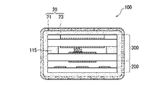
- 3 is a cross-sectional view orthogonal to the direction of the axis L of the detection element unit 300.
- the gas sensor 1 includes a gas sensor element 100 including a detection element unit 300 and a heater unit 200 stacked on the detection element unit 300, a metal shell that holds the gas sensor element 100, etc. (Corresponding to a “housing” in the range) 30, a protector 24 attached to the tip of the metal shell 30, and the like.
- the gas sensor element 100 is arranged so as to extend in the direction of the axis L.
- the heater unit 200 includes a first base 101 and a second base 103 mainly composed of alumina, and a heating element 102 mainly composed of platinum sandwiched between the first base 101 and the second base 103. have.
- the heating element 102 has a heating part 102a located on the tip side and a pair of heater lead parts 102b extending from the heating part 102a along the longitudinal direction of the first base 101.
- the terminal of the heater lead portion 102b is electrically connected to the heater side pad 120 via a conductor formed in the heater side through hole 101a provided in the first base 101.
- the detection element unit 300 includes an oxygen concentration detection cell 130 and an oxygen pump cell 140.
- the oxygen concentration detection cell 130 is formed of a first solid electrolyte body 105 and a first electrode 104 and a second electrode 106 formed on both surfaces of the first solid electrolyte 105.
- the first electrode 104 is formed of a first electrode portion 104 a and a first lead portion 104 b extending from the first electrode portion 104 a along the longitudinal direction of the first solid electrolyte body 105.
- the second electrode 106 is formed of a second electrode portion 106 a and a second lead portion 106 b extending from the second electrode portion 106 a along the longitudinal direction of the first solid electrolyte body 105.
- the first electrode 104 and the second electrode 106 correspond to “a pair of electrodes” in the claims.
- the terminals of the first lead portion 104b are first through holes 105a provided in the first solid electrolyte body 105, second through holes 107a provided in an insulating layer 107 described later, and second terminals provided in the second solid electrolyte body 109.
- the detection element side pad 121 is electrically connected through a conductor formed in each of the fourth through hole 109a and the sixth through hole 111a provided in the protective layer 111.
- the terminal of the second lead portion 106b is a third through hole 107b provided in the insulating layer 107 described later, a fifth through hole 109b provided in the second solid electrolyte body 109, and a seventh through hole provided in the protective layer 111. It electrically connects with the detection element side pad 121 through the conductor formed in each of 111b.
- the oxygen pump cell 140 is formed of the second solid electrolyte body 109 and the third electrode 108 and the fourth electrode 110 formed on both surfaces of the second solid electrolyte body 109.
- the third electrode 108 is formed of a third electrode portion 108 a and a third lead portion 108 b extending from the third electrode portion 108 a along the longitudinal direction of the second solid electrolyte body 109.
- the fourth electrode 110 is formed of a fourth electrode portion 110 a and a fourth lead portion 110 b extending from the fourth electrode portion 110 a along the longitudinal direction of the second solid electrolyte body 109.
- the third electrode 108 and the fourth electrode 110 correspond to “a pair of electrodes” in the claims.
- the terminal of the 3rd lead part 108b is the detection element side via the conductor formed in each of the 5th through hole 109b provided in the 2nd solid electrolyte body 109, and the 7th through hole 111b provided in protective layer 111. It is electrically connected to the pad 121.
- the terminal of the fourth lead portion 110b is electrically connected to the detection element side pad 121 via a conductor formed in an eighth through hole 111c provided in the protective layer 111 described later.
- the second lead portion 106b and the third lead portion 108b are at the same potential.
- the first solid electrolyte body 105 and the second solid electrolyte body 109 are partially stabilized zirconia sintered bodies obtained by adding yttria (Y 2 O 3 ) or calcia (CaO) as a stabilizer to zirconia (ZrO 2 ). It is composed of
- the heating element 102, the first electrode 104, the second electrode 106, the third electrode 108, the fourth electrode 110, the heater side pad 120, and the detection element side pad 121 can be formed of a platinum group element.
- Pt, Rh, Pd etc. can be mentioned as a suitable platinum group element which forms these, These can also be used individually by 1 type, and can also use 2 or more types together.
- the heating element 102, the first electrode 104, the second electrode 106, the third electrode 108, the fourth electrode 110, the heater side pad 120, and the detection element side pad 121 are mainly composed of Pt in consideration of heat resistance and oxidation resistance. It is even more preferable to form it.
- the heating element 102, the first electrode 104, the second electrode 106, the third electrode 108, the fourth electrode 110, the heater side pad 120, and the detection element side pad 121 include ceramic components in addition to the main platinum group element. It is preferable to contain. This ceramic component is preferably the same component as the main material on the side to be laminated (for example, the main component of the first solid electrolyte body 105 and the second solid electrolyte body 109) from the viewpoint of fixation. .
- An insulating layer 107 is formed between the oxygen pump cell 140 and the oxygen concentration detection cell 130.
- the insulating layer 107 includes an insulating portion 114 and a diffused resistor portion 115.
- a hollow measurement chamber 107c is formed at a position corresponding to the second electrode part 106a and the third electrode part 108a.
- the measurement chamber 107c communicates with the outside in the width direction of the insulating layer 107, and the diffusion resistance portion 115 that realizes gas diffusion between the outside and the measurement chamber 107c under a predetermined rate-limiting condition. Is arranged.
- the insulating part 114 is not particularly limited as long as it is an insulating ceramic sintered body, and examples thereof include oxide ceramics such as alumina and mullite.
- the diffusion resistance portion 115 is a porous body made of alumina.
- the diffusion resistance unit 115 determines the rate when the detection gas flows into the measurement chamber 107c.
- a protective layer 111 is formed on the surface of the second solid electrolyte body 109 so as to sandwich the fourth electrode 110.
- the protective layer 111 sandwiches the fourth electrode portion 110a, sandwiches the porous electrode protection portion 113a for protecting the fourth electrode portion 110a from poisoning, and the fourth lead portion 110b. It comprises a reinforcing part 112 for protecting the second solid electrolyte body 109.
- the metal shell 30 is made of SUS430, and has a male screw portion 31 for attaching the gas sensor to the exhaust pipe, and a hexagonal portion 32 to which an attachment tool is applied at the time of attachment.
- the metal shell 30 is provided with a metal side step portion 33 that protrudes radially inward, and this metal side step portion 33 supports a metal holder 34 for holding the gas sensor element 100.
- a ceramic holder 35 and a talc 36 are arranged in this order from the tip side.
- the talc 36 includes a first talc 37 disposed in the metal holder 34 and a second talc 38 disposed over the rear end of the metal holder 34.
- the gas sensor element 100 is fixed to the metal holder 34 by compressing and filling the first talc 37 in the metal holder 34.
- the second talc 38 is compressed and filled in the metal shell 30, thereby ensuring a sealing property between the outer surface of the gas sensor element 100 and the inner surface of the metal shell 30.
- An alumina sleeve 39 is disposed on the rear end side of the second talc 38.
- the sleeve 39 is formed in a multi-stage cylindrical shape, is provided with a shaft hole 39a along the axis, and the gas sensor element 100 is inserted through the shaft hole 39a.
- the caulking portion 30 a on the rear end side of the metal shell 30 is bent inward, and the sleeve 39 is pressed to the front end side of the metal shell 30 through the stainless steel ring member 40.
- a metal protector 24 having a plurality of gas intake holes 24a is attached to the outer periphery on the front end side of the metallic shell 30 by covering the distal end portion of the gas sensor element 100 protruding from the distal end of the metallic shell 30 by welding.
- This protector 24 has a double structure, a cylindrical outer protector 41 having a uniform outer diameter on the outer side, and an outer diameter of the rear end part 42a on the inner side from the outer diameter of the front end part 42b.
- An inner protector 42 having a bottomed cylindrical shape that is formed to be larger is also arranged.
- the front end side of the outer tube 25 made of SUS430 is inserted.
- the outer cylinder 25 has a distal end portion 25a whose diameter is enlarged on the distal end side fixed to the metal shell 30 by laser welding or the like.
- a separator 50 is disposed inside the rear end side of the outer cylinder 25, and a holding member 51 is interposed in a gap between the separator 50 and the outer cylinder 25.
- the holding member 51 is fixed by the outer cylinder 25 and the separator 50 by engaging a protrusion 50 a of the separator 50 described later and caulking the outer cylinder 25.
- the separator 50 has a through hole 50b for inserting the lead wires 11 to 15 for the detection element section 300 and the heater section 200 from the front end side to the rear end side (note that the lead wires 14, 15 is not shown).
- the connection hole 16 for connecting the lead wires 11 to 15 to the detection element side pad 121 of the detection element unit 300 and the heater side pad 120 of the heater unit 200 is accommodated in the through hole 50b.
- Each of the lead wires 11 to 15 is connected to a connector (not shown) outside. Electric signals are input and output between the external devices such as the ECU and the lead wires 11 to 15 through this connector. Further, although not shown in detail, each of the lead wires 11 to 15 has a structure in which the lead wires are covered with an insulating film made of resin.
- a substantially cylindrical rubber cap 52 for closing the opening 25b on the rear end side of the outer cylinder 25 is disposed on the rear end side of the separator 50.
- the rubber cap 52 is fixed to the outer cylinder 25 by caulking the outer periphery of the outer cylinder 25 toward the radially inner side in a state where the rubber cap 52 is mounted in the rear end of the outer cylinder 25.
- the rubber cap 52 is also provided with through holes 52a for inserting the lead wires 11 to 15 from the front end side to the rear end side.
- FIG. 3 is a partial enlarged cross-sectional view of the gas sensor element 100 of FIG. 1 on the front end side, and an inner porous layer 21 is provided immediately above the surface of the laminate of the detection element unit 300 and the heater unit 200.
- An outer porous layer 23 is formed so as to cover the outer surface of 21. That is, the porous protective layer 20 is provided so as to cover the entire circumference of the detection unit 150 provided at the tip side portion of the gas sensor element 100.
- the detection unit 150 is an electrode unit included in the detection element unit 300 (in FIG.
- the first electrode unit 104a, the second electrode unit 106a, the third electrode unit 108a, and the fourth electrode unit 110a which will be described later.
- the first electrode 104C, the second electrode 106C, the third electrode 108C, the fourth electrode 110C, the fifth electrode 152, and the sixth electrode 153) and the solid electrolyte body sandwiched between the electrode portions In FIG. 2, the first solid electrolyte body 105 and the second solid electrolyte body 109 are shown.
- the first solid electrolyte body 105C, the second solid electrolyte body 109C, and the third solid electrolyte body 151 are shown.
- the measurement chamber (the measurement chamber 107c in FIG.
- the porous protective layer 20 covers the laminated body (the tip side portion of the gas sensor element 100) including the detection element unit 300. Become. On the other hand, when the gas sensor element 100 does not include the heater unit 200, the porous protective layer 20 may cover the entire circumference of the detection element unit 300 (detection unit 150).
- the porous protective layer 20 includes the front end surface of the gas sensor element 100, is formed to extend to the rear end side along the direction of the axis L, and 4 on the front and back surfaces and both side surfaces of the gas sensor element 100 (laminated body). The surface is completely surrounded (see FIG. 4).
- FIG. 4 is a schematic cross-sectional view orthogonal to the axis L direction of the gas sensor element 100 including the inner porous layer 21 and the outer porous layer 23.
- the porosity of the inner porous layer 21 is higher than the porosity of the outer porous layer 23.
- the pores formed in the inner porous layer 21 and the outer porous layer 23 have a three-dimensional network structure so as to allow gas permeation.
- poisonous substances and water droplets are effectively captured by the outer porous layer 23 having a reduced porosity. Therefore, it is difficult to reach the detection element unit 300 (the detection unit 150).
- the porosity of the inner porous layer 21 is made larger than the porosity of the outer porous layer 23, the total volume of voids (spaces) contained in the inner porous layer 21 is increased to provide heat insulation. Therefore, even if the outer porous layer 23 side is submerged and cooled, the inner detection unit 150 is hardly cooled rapidly, and the gas sensor element 100 is damaged by the submergence even when the detection unit 150 is heated by the heater unit 200. There is an effect that can be effectively suppressed.
- the inner porous layer 21 is mainly composed of ceramic particles 21a and ceramic fibers 21b having an average fiber length of 70 to 200 ⁇ m whose main component is ceramic. The generation of cracks in the layer 21 can be suppressed and the layer strength can be improved. This is considered to increase the layer strength because the ceramic fiber 21b added to the inner porous layer 21 strengthens the inner porous layer 21.
- the ceramic fiber 21b refers to fibrous particles having a diameter of 3 to 5 ⁇ m.
- the content of the ceramic fiber 21b in the inner porous layer 21 is 25 to 75 vol% when the content of the ceramic particles and the ceramic fiber is 100 vol%.
- the content of the ceramic fiber 21b in the inner porous layer 21 is less than 25 vol%, the crack suppressing effect in the layer is not sufficient, and when it exceeds 75 vol%, the content of the ceramic fiber 21b is excessively increased. Since the sintering (bonding between the particles) of the ceramic particles 21a in the inner porous layer 21 is inhibited, the layer strength of the inner porous layer 21 may be lowered.
- content of the ceramic particle 21a and the ceramic fiber 21b is calculated
- a ceramic fiber 21b1 having a maximum fiber length LMax is extracted from the ceramic fibers 21b included in the plurality of regions.
- the ceramic fiber 21b having the maximum fiber length LMax included in each of the above regions protrudes from the region, the ceramic fiber 21b does not protrude from the region and is completely included in the region. , Enlarge the area.
- the vertical and horizontal dimensions of the region are also adopted as the vertical and horizontal sizes when determining other regions,
- the contents of the ceramic particles 21a and the ceramic fibers 21b included in the region are obtained, and each is calculated by averaging each of the plurality of regions.
- the average fiber length of the ceramic fiber 21b is set to 70 to 200 ⁇ m.
- the average fiber length of the ceramic fibers 21b is less than 70 ⁇ m, the effect of suppressing cracks in the layer is insufficient, and if it exceeds 200 ⁇ m, the ceramic fibers 21b become too long and the alumina particles 21a in the inner porous layer 21 Sintering (bonding between particles) is hindered, so that the layer strength of the inner porous layer 21 may be lowered.
- the average fiber length of the ceramic fiber 21b is calculated
- the region is expanded until the ceramic fiber 21b does not protrude from the region and is completely included in the region.
- the ceramic fibers 21b having a fiber length of LMax / 2 or more are extracted, and the extracted ceramic fibers 21b (including the ceramic fibers 21b1) are extracted.
- the average fiber length is preferably 0.1 to 1.0 ⁇ m.
- Examples of the ceramic fiber 21b include one or more ceramic fibers selected from the group consisting of alumina, silica, spinel, zirconia, mullite, zircon, cordierite, silicon carbide, silicon nitride, and titania.
- Examples of the ceramic particles 21a include one or more ceramic particles selected from the group consisting of alumina, silica, spinel, zirconia, mullite, zircon and cordierite, silicon carbide, silicon nitride, and titania.
- the inner porous layer 21 can be formed by applying a slurry containing the ceramic particles 21a and the ceramic fibers 21b described above by a dipping method, a printing method, a spraying method, or the like, and then bonding them by baking or the like.
- a slurry containing the ceramic particles 21a pores can be formed in the skeleton of the film, but when the slurry containing the particles is added with a burnable pore former, the pore former is obtained. Since the burned-out portion becomes pores, the inner porous layer 21 can have a high porosity, which is preferable.
- the pore former for example, carbon, resin beads, organic or inorganic binder particles can be used.
- the porosity of the inner porous layer 21 obtained by image analysis described later is 50 to 75% because the above-described heat insulation effect is easily obtained. If the porosity of the inner porous layer 21 is less than 50%, the gas diffusion resistance of the inner porous layer 21 tends to be high, and it may be difficult to produce a film exceeding 75%.
- the thickness of the inner porous layer 21 is preferably 20 to 800 ⁇ m.
- the outer porous layer 23 can be formed by bonding, for example, one or more ceramic particles selected from the group of alumina, spinel, zirconia, mullite, zircon, and cordierite by firing or the like. By sintering the slurry containing these particles, pores are formed in the skeleton of the coating when the gaps between the ceramic particles and the organic or inorganic binder in the slurry are burned away. Further, it is preferable that the porosity of the outer porous layer 23 obtained by image analysis described later is 30 to 50%, since the gas permeability is not lowered while the barrier property of poisonous substances and water droplets is secured.
- the thickness of the outer porous layer 23 is preferably 100 to 800 ⁇ m.
- the porosity of the inner porous layer 21 and the outer porous layer 23 is determined as follows. First, based on a cross-sectional photograph (SEM image), binarization is performed using a commercially available image analysis software at each of a plurality of positions of the inner porous layer 21 and the outer porous layer 23, and the ratio of the black portion of the cross-sectional photograph I will seek. Since the black part of the cross-sectional photograph corresponds to the pores and the white part corresponds to the skeleton of the film, the more black parts, the higher the porosity. Then, the porosity obtained by performing image analysis at the plurality of positions of the inner porous layer 21 and the outer porous layer 23 was averaged, and the porosity of each layer was obtained.
- SEM image cross-sectional photograph
- both the inner porous layer 21 and the outer porous layer 23 cover the entire circumference of the tip portion of the laminate. Since the porosity of the inner porous layer 21 is higher than the porosity of the outer porous layer 23, the inner porous layer 21 is covered on the entire circumference of the tip of the laminate of the detection element unit 300 and the heater unit 200. By doing so, the total volume of the voids of the inner porous layer 21 on the laminate side becomes larger and the heat insulating property is further increased, and even if the outer porous layer 23 side is submerged and cooled, the gas sensor element 100 is hardly cooled rapidly. . Therefore, even when the detection unit 150 is heated by the heater unit 200, the gas sensor element 100 can be more effectively prevented from being damaged by water.
- porous layer may be provided between the inner porous layer 21 and the outer porous layer 23, or another porous layer may be provided outside the outer porous layer 23.
- the slurry to be the inner porous layer 21 and the outer porous layer 23 may be sequentially applied and sintered by a dipping method or the like.
- the slurry to be the inner porous layer 21 may be applied and sintered, and then the slurry to be the outer porous layer 23 may be applied and sintered.
- the slurry for forming the inner porous layer 21 and the outer porous layer 23 may be sequentially applied and sintered at a time.
- the inner porous layer 21 and the outer porous layer 23 may be manufactured by a thermal spraying method, a printing method, or a spray method.
- the inner porous layer 21 and the outer porous layer 23 may be formed by different methods among dipping, spraying, printing, and spraying.
- FIG. 6 shows a modification of the gas sensor element 100 in the embodiment.
- a detection element part and a heater part are the same as 1st Embodiment (oxygen sensor element of FIG. 2), description is abbreviate
- the inner porous layer 21 ⁇ / b> B does not cover the entire periphery of the front end portion of the multilayer body, and covers only the periphery of the diffusion resistance portion 115.
- the outer porous layer 23 covers the entire circumference of the tip of the laminate. Also in the example of FIG.
- the porosity of the inner porous layer 21B is higher than the porosity of the outer porous layer 23B, and poisonous substances and water droplets are effectively captured by the outer porous layer 23B with a reduced porosity. Therefore, it is difficult to reach the detection element unit (detection unit 150B).
- the porosity of the inner porous layer 21B is made larger than the porosity of the outer porous layer 23B, the total volume of voids (spaces) contained in the inner porous layer 21B is increased, thereby providing heat insulation.
- the layer strength of the inner porous layer 21 ⁇ / b> B can be increased by using the inner porous layer 21 ⁇ / b> B as a main component with the above-described ceramic particles and ceramic fibers whose main component is ceramic.
- gas sensor NOx sensor
- the gas sensor according to the second embodiment is the same as the gas sensor according to the first embodiment except that the configuration of the gas sensor element 100C, the inner porous layer 21C, and the outer porous layer 23C is different. Description and illustration of the metal shell and the like holding the element 100C are omitted.
- the gas sensor element (NOx sensor element) 100C has an elongated and long plate shape, and has three layers of plate-like solid electrolyte bodies 109C, 105C, and 151, and insulators 180 and 185 made of alumina or the like between them. The layered structure is sandwiched between these layers, and these stacked structures constitute the detection element portion 300C. Further, on the outer layer on the solid electrolyte body 151 side (the side opposite to the solid electrolyte body 105C in FIG. 1), sheet-like insulating layers 103C and 101C mainly composed of alumina are laminated, and a heater pattern mainly composed of Pt therebetween. A heater unit 200C in which 102C is embedded is provided.
- the solid electrolyte bodies 109C, 105C, 151 are made of zirconia, which is a solid electrolyte, and have oxygen ion conductivity.
- the detection element unit 300C includes the following first pump cell (Ip1 cell) 140C, oxygen concentration detection cell (Vs cell) 130C, and second pump cell (Ip2 cell) 150.
- the first pump cell 140C is formed of a second solid electrolyte body 109C and a third electrode 108C and a fourth electrode 110C formed on both surfaces thereof.
- a porous protective layer 114 made of ceramic is provided on the surface of the fourth electrode 110C, and the fourth electrode 110C is exposed to a toxic gas (reducing atmosphere) contained in the exhaust gas. Protects from deterioration.
- the first pump cell 140C is different from the oxygen pump cell 140 in that oxygen is pumped and pumped (so-called oxygen pumping) between the first measurement chamber 107c2 described later and the outside through the second solid electrolyte body 109C. It has a similar function.
- the third electrode 108C and the fourth electrode 110C correspond to “a pair of electrodes” in the claims.
- the oxygen concentration detection cell 130C is formed of the first solid electrolyte body 105C and the first electrode 104C and the second electrode 106C formed on both surfaces thereof.
- the oxygen concentration detection cell 130C can generate an electromotive force in accordance with an oxygen partial pressure difference between the first measurement chamber 107c2 separated by the solid electrolyte body 105C and a reference oxygen chamber 170 described later.
- a hollow first measurement chamber 107c2 as a small space is formed between the solid electrolyte body 109C and the solid electrolyte body 105C, and the second electrode 106C and the third electrode 108C are located in the first measurement chamber 107c2.
- the first measurement chamber 107c2 is a small space in which the measurement target gas is first introduced from the outside into the gas sensor element 100C.
- the first measurement chamber 107c2 has a porous first gas chamber element 100C that is interposed between the first measurement chamber 107c2 and the outside to adjust the diffusion of the measurement target gas into the first measurement chamber 107c2.
- One diffusion resistance portion 115C is provided.
- a second diffusion that adjusts gas diffusion is also provided on the rear end side of the gas sensor element 100C of the first measurement chamber 107c2 as a partition between an opening 181 connected to the second measurement chamber 160 described later and the first measurement chamber 107c2.
- a resistance portion 117 is provided.
- the first electrode 104C and the second electrode 106C correspond to “a pair of electrodes” in the claims.
- the gas sensor element 100 ⁇ / b> C includes a second pump cell 150 formed of a third solid electrolyte body 151, a fifth electrode 152, and a sixth electrode 153.
- the third solid electrolyte body 151 is disposed so as to face the solid electrolyte body 105C with the insulator 185 interposed therebetween.
- the insulator 185 is not disposed at the position where the fifth electrode 152 is formed, and a reference oxygen chamber 170 is formed as an independent space.
- the first electrode 104C of the oxygen concentration detection cell 130C is also arranged.
- the reference oxygen chamber 170 is filled with a ceramic porous body.
- the insulator 185 is not disposed at the position where the sixth electrode 153 is formed, and the insulator 185 is separated from the reference oxygen chamber 170, and the hollow second measurement chamber 160 as an independent small space is provided. Is formed.
- the solid electrolyte body 105C and the insulator 180 are provided with openings 125 and 141 so as to communicate with the second measurement chamber 160.
- the first measurement chamber 107c2 and the opening 181 are provided.
- the second pump cell 150 can pump oxygen between the reference oxygen chamber 170 and the second measurement chamber 160 separated by the insulator 185.
- the fifth electrode 152 and the sixth electrode 153 correspond to “a pair of electrodes” in the claims.
- an inner porous layer 21C is provided immediately above the surface of the laminate of the detection element unit 300C and the heater unit 200C, and an outer porous layer 23C is formed to cover the outer surface of the inner porous layer 21C. That is, the porous protective layer 20 (the inner porous layer 21C and the outer porous layer 23C) is provided so as to cover the entire circumference on the front end side of the gas sensor element 100C.
- another measurement chamber (second measurement chamber 160) communicates with the rear end side of the first measurement chamber 107c2, and the sixth electrode 153 is connected to the second measurement chamber 160.
- the porous protective layer 20 extends from the rear end of the second measurement chamber 160 to the rear end side so as to cover at least the rear end of the sixth electrode 153.
- the porous protective layer 20 is formed so as to completely surround the four surfaces of the front and back surfaces and both side surfaces of the gas sensor element 100C (laminated body), as in the first embodiment.
- the porosity of the outer porous layer 23C by reducing the porosity of the outer porous layer 23C relative to the porosity of the inner porous layer 21C, poisonous substances and water droplets have a reduced porosity. Therefore, it is difficult to reach the detection element unit 300C (detection unit 150C).
- the porosity of the inner porous layer 21C by making the porosity of the inner porous layer 21C larger than the porosity of the outer porous layer 23C, the total volume of voids (spaces) contained in the inner porous layer 21C is increased, thereby providing heat insulation.
- the inner detection unit 150C is difficult to be rapidly cooled, and the gas sensor element 100C is damaged by the submersion even when the detection unit 150C is heated by the heater unit 200C. There is an effect that can be effectively suppressed.
- the inner porous layer 21 ⁇ / b> C layer strength can be increased by using the inner porous layer 21 ⁇ / b> C as a main component with the above-described ceramic particles and ceramic fibers whose main component is ceramic.
- the NOx concentration detection operation by the NOx sensor element 100C will be briefly described.
- oxygen is pumped or pumped between the first measurement chamber 107c2 and the outside in the first pump cell 140C so that the potential difference between the electrodes 104C and 106C is constant around 425 mV.
- the exhaust gas whose oxygen concentration is adjusted in the first measurement chamber 107 c 2 is introduced into the second measurement chamber 160 through the second gas diffusion layer 117.
- NOx in the exhaust gas in contact with the sixth electrode 153 in the second measurement chamber 160 is decomposed (reduced) into N 2 and O 2 using the sixth electrode 153 as a catalyst.
- the decomposed oxygen receives electrons from the sixth electrode 153, flows into the third solid electrolyte body 151 as oxygen ions, and moves to the fifth electrode 152.
- the residual oxygen remaining in the first measurement chamber 107c2 is also moved into the quasi-oxygen chamber 170 by the Ip2 cell 150.
- the current flowing through the Ip2 cell 150 is a current derived from NOx and a current derived from residual oxygen.
- the concentration of residual oxygen remaining in the first measurement chamber 107c2 is adjusted to a predetermined value as described above, the current derived from the residual oxygen can be regarded as substantially constant, and the current derived from NOx.
- the current flowing through the Ip2 cell 150 is proportional to the NOx concentration.
- the present invention is not limited to the above embodiment, and can be applied to any gas sensor (gas sensor element) having a detection unit having a solid electrolyte body and a pair of electrodes.
- the oxygen sensor (oxygen sensor element) of the present embodiment can be applied to NOx sensors (NOx sensor elements), but is not limited to these uses, and it goes without saying that the present invention covers various modifications and equivalents included in the spirit and scope of the present invention.
- the present invention may be applied to an HC sensor (HC sensor element) that detects HC concentration.
- the gas sensor element of Example 1 will be described.
- the following slurry A to be the inner porous layer 21 has an appropriate viscosity on the front surface (front and back surfaces and both side surfaces) of the plate-like gas sensor element (entire region air-fuel ratio sensor element) 100 shown in FIGS. It adjusted so that it might become, and it apply
- Slurry A Alumina particles (average particle size 0.1 ⁇ m) and alumina fibers (average fiber length 100 ⁇ m total amount 40 vol%, carbon powder (average particle size 20.0 ⁇ m) 60 vol%, alumina sol (external blend) 10 wt% are weighed Further, ethanol was added and stirred, and the ratio of alumina powder and alumina fiber in the slurry A was changed as shown in Table 1.
- the average particle size was determined by a laser diffraction scattering method.
- the average fiber length of the alumina fibers was averaged by measuring the length of each alumina fiber before mixing with the slurry A.
- the following slurry B which becomes the inner porous layer 21, has an appropriate viscosity on the front surface (front and back surfaces and both side surfaces) of the plate-like gas sensor element (entire region air-fuel ratio sensor element) 100 shown in FIGS. It adjusted so that it might become, and it apply
- the slurry C to be the outer porous layer 23 was adjusted to have an appropriate viscosity on the surface of the inner porous layer 21 and applied to a thickness of 200 ⁇ m by a dip (immersion) method. Thereafter, in order to volatilize excess organic solvent in the slurry C, the slurry is dried for several hours with a dryer set at 200 ° C., and further, in the atmosphere, at 1100 ° C. for 3 hours, the inner porous layer 21 and the outer porous layer 23 was fired.
- Slurry B Alumina particles (average particle size 0.1 ⁇ m) 20 vol%, alumina fibers 20 vol%, carbon powder (average particle size 20.0 ⁇ m) 60 vol%, alumina sol (external blend) 10 wt%, and ethanol was added. And prepared by stirring. The average fiber length of the alumina fibers in the slurry B was changed as shown in Table 2. The average particle size was determined by a laser diffraction scattering method. As in Example 1, the average fiber length of the alumina fibers at the stage of mixing with the slurry B, and the contents of the alumina particles and the alumina fibers were regarded as values in the inner porous layer 21 after sintering. .
- Slurry C Alumina particles (average particle size 0.1 ⁇ m) 40 vol%, spinel particles (average particle size 40 ⁇ m) 60 vol%, alumina sol (external blend) 10 wt% were weighed and further ethanol was added and stirred. The average particle size was determined by a laser diffraction scattering method.
Landscapes
- Chemical & Material Sciences (AREA)
- Life Sciences & Earth Sciences (AREA)
- Health & Medical Sciences (AREA)
- Physics & Mathematics (AREA)
- Chemical Kinetics & Catalysis (AREA)
- Electrochemistry (AREA)
- Molecular Biology (AREA)
- Analytical Chemistry (AREA)
- Biochemistry (AREA)
- General Health & Medical Sciences (AREA)
- General Physics & Mathematics (AREA)
- Immunology (AREA)
- Pathology (AREA)
- Measuring Oxygen Concentration In Cells (AREA)
Priority Applications (2)
| Application Number | Priority Date | Filing Date | Title |
|---|---|---|---|
| US14/355,457 US9234870B2 (en) | 2011-11-11 | 2012-11-20 | Gas sensor element, and gas sensor |
| EP12855544.8A EP2818855B1 (de) | 2011-11-11 | 2012-11-20 | Gassensorelement und gassensor |
Applications Claiming Priority (2)
| Application Number | Priority Date | Filing Date | Title |
|---|---|---|---|
| JP2011247132A JP2013104706A (ja) | 2011-11-11 | 2011-11-11 | ガスセンサ素子及びガスセンサ |
| JP2011-247132 | 2011-11-11 |
Publications (2)
| Publication Number | Publication Date |
|---|---|
| WO2013084097A2 true WO2013084097A2 (ja) | 2013-06-13 |
| WO2013084097A3 WO2013084097A3 (ja) | 2014-11-06 |
Family
ID=48575012
Family Applications (1)
| Application Number | Title | Priority Date | Filing Date |
|---|---|---|---|
| PCT/IB2012/056552 Ceased WO2013084097A2 (ja) | 2011-11-11 | 2012-11-20 | ガスセンサ素子及びガスセンサ |
Country Status (4)
| Country | Link |
|---|---|
| US (1) | US9234870B2 (de) |
| EP (1) | EP2818855B1 (de) |
| JP (1) | JP2013104706A (de) |
| WO (1) | WO2013084097A2 (de) |
Families Citing this family (25)
| Publication number | Priority date | Publication date | Assignee | Title |
|---|---|---|---|---|
| JP2013104706A (ja) | 2011-11-11 | 2013-05-30 | Ngk Spark Plug Co Ltd | ガスセンサ素子及びガスセンサ |
| JP5390682B1 (ja) | 2012-11-13 | 2014-01-15 | 日本特殊陶業株式会社 | ガスセンサ素子及びガスセンサ |
| CN105190300B (zh) * | 2013-03-12 | 2019-07-23 | 罗伯特·博世有限公司 | 固体电解质传感器元件的制造方法,其含两多孔陶瓷层用于探测测量气体腔室中测量气体的至少一特性 |
| JP6359373B2 (ja) | 2013-09-05 | 2018-07-18 | 日本特殊陶業株式会社 | ガスセンサ素子及びガスセンサ |
| CN103529102A (zh) * | 2013-10-25 | 2014-01-22 | 郑龙华 | 氧传感器多层复合保护层及其制造方法 |
| JP6169946B2 (ja) * | 2013-10-29 | 2017-07-26 | 日本特殊陶業株式会社 | ガスセンサ素子、ガスセンサおよびガスセンサ素子の製造方法 |
| JP6359436B2 (ja) * | 2014-01-17 | 2018-07-18 | 日本特殊陶業株式会社 | NOxセンサ |
| JP6475074B2 (ja) * | 2014-07-18 | 2019-02-27 | トヨタ自動車株式会社 | ガスセンサ素子 |
| US10228346B2 (en) | 2014-12-04 | 2019-03-12 | Ngk Insulators, Ltd. | Gas sensor element and gas sensor |
| JP6857051B2 (ja) * | 2016-04-20 | 2021-04-14 | 日本特殊陶業株式会社 | ガスセンサ素子およびガスセンサ |
| JP6761369B2 (ja) * | 2017-03-30 | 2020-09-23 | 日本碍子株式会社 | ガスセンサ素子 |
| JP6761371B2 (ja) * | 2017-03-30 | 2020-09-23 | 日本碍子株式会社 | ガスセンサ素子 |
| JP7082922B2 (ja) * | 2018-08-03 | 2022-06-09 | 日本碍子株式会社 | センサ素子 |
| JP7184561B2 (ja) * | 2018-08-03 | 2022-12-06 | 日本碍子株式会社 | センサ素子 |
| JP7157595B2 (ja) * | 2018-08-30 | 2022-10-20 | 日本碍子株式会社 | センサ素子 |
| JP7089990B2 (ja) * | 2018-08-30 | 2022-06-23 | 日本碍子株式会社 | センサ素子 |
| DE112019003810T5 (de) * | 2018-09-28 | 2021-05-27 | Ngk Insulators, Ltd. | Keramikstruktur und sensorelement für einen gassensor |
| WO2020144827A1 (ja) * | 2019-01-10 | 2020-07-16 | 日本碍子株式会社 | ガスセンサ |
| JP7181811B2 (ja) * | 2019-02-26 | 2022-12-01 | 日本碍子株式会社 | ガスセンサ素子及びガスセンサ |
| JP7261640B2 (ja) * | 2019-03-29 | 2023-04-20 | 日本碍子株式会社 | ガスセンサのセンサ素子 |
| JP7195996B2 (ja) * | 2019-03-29 | 2022-12-26 | 日本碍子株式会社 | ガスセンサのセンサ素子 |
| JP7227824B2 (ja) * | 2019-03-29 | 2023-02-22 | 日本碍子株式会社 | ガスセンサのセンサ素子 |
| DE112020001680T5 (de) * | 2019-03-29 | 2022-02-24 | Ngk Insulators, Ltd. | Sensorelement eines Gassensors |
| JP7391547B2 (ja) * | 2019-06-13 | 2023-12-05 | 日本特殊陶業株式会社 | ガスセンサ |
| JP7646516B2 (ja) * | 2021-10-25 | 2025-03-17 | 日本碍子株式会社 | センサ素子及びガスセンサ |
Citations (2)
| Publication number | Priority date | Publication date | Assignee | Title |
|---|---|---|---|---|
| JP2003322632A (ja) | 2002-02-28 | 2003-11-14 | Ngk Spark Plug Co Ltd | セラミックヒータ、積層型ガスセンサ素子及びその製造方法、並びに積層型ガスセンサ素子を備えるガスセンサ |
| JP2007206082A (ja) | 2002-02-28 | 2007-08-16 | Ngk Spark Plug Co Ltd | セラミックヒータ、積層型ガスセンサ素子及びその製造方法、並びに積層型ガスセンサ素子を備えるガスセンサ |
Family Cites Families (9)
| Publication number | Priority date | Publication date | Assignee | Title |
|---|---|---|---|---|
| US5593558A (en) * | 1994-06-09 | 1997-01-14 | Nippondenso Co., Ltd. | Oxygen concentration detector |
| JP3736020B2 (ja) * | 1997-04-16 | 2006-01-18 | 松下電器産業株式会社 | ガスセンサ |
| CN1142428C (zh) * | 2000-12-28 | 2004-03-17 | 康达(成都)电子有限公司 | 氧传感器及其制造方法 |
| GB2387230B (en) | 2002-02-28 | 2005-12-21 | Ngk Spark Plug Co | Prismatic ceramic heater for heating gas sensor element, prismatic gas sensor element in multi-layered structure including the prismatic ceramic heater, |
| JP2006171013A (ja) * | 2002-02-28 | 2006-06-29 | Ngk Spark Plug Co Ltd | セラミックヒータ、積層型ガスセンサ素子及び積層型ガスセンサ素子を備えるガスセンサ |
| DE102005062598A1 (de) * | 2005-12-27 | 2007-06-28 | Robert Bosch Gmbh | Gassensorelement und Verfahren zur Herstellung des Gassensorelements |
| JP2009080110A (ja) * | 2007-09-07 | 2009-04-16 | Denso Corp | ガスセンサ素子及びその製造方法 |
| JP5416757B2 (ja) * | 2011-02-22 | 2014-02-12 | 日本特殊陶業株式会社 | ガスセンサ素子及びガスセンサ |
| JP2013104706A (ja) | 2011-11-11 | 2013-05-30 | Ngk Spark Plug Co Ltd | ガスセンサ素子及びガスセンサ |
-
2011
- 2011-11-11 JP JP2011247132A patent/JP2013104706A/ja not_active Withdrawn
-
2012
- 2012-11-20 WO PCT/IB2012/056552 patent/WO2013084097A2/ja not_active Ceased
- 2012-11-20 US US14/355,457 patent/US9234870B2/en active Active
- 2012-11-20 EP EP12855544.8A patent/EP2818855B1/de active Active
Patent Citations (2)
| Publication number | Priority date | Publication date | Assignee | Title |
|---|---|---|---|---|
| JP2003322632A (ja) | 2002-02-28 | 2003-11-14 | Ngk Spark Plug Co Ltd | セラミックヒータ、積層型ガスセンサ素子及びその製造方法、並びに積層型ガスセンサ素子を備えるガスセンサ |
| JP2007206082A (ja) | 2002-02-28 | 2007-08-16 | Ngk Spark Plug Co Ltd | セラミックヒータ、積層型ガスセンサ素子及びその製造方法、並びに積層型ガスセンサ素子を備えるガスセンサ |
Non-Patent Citations (1)
| Title |
|---|
| See also references of EP2818855A4 |
Also Published As
| Publication number | Publication date |
|---|---|
| US9234870B2 (en) | 2016-01-12 |
| WO2013084097A3 (ja) | 2014-11-06 |
| EP2818855B1 (de) | 2020-03-04 |
| EP2818855A4 (de) | 2015-11-11 |
| EP2818855A2 (de) | 2014-12-31 |
| JP2013104706A (ja) | 2013-05-30 |
| US20140291150A1 (en) | 2014-10-02 |
Similar Documents
| Publication | Publication Date | Title |
|---|---|---|
| JP5390682B1 (ja) | ガスセンサ素子及びガスセンサ | |
| WO2013084097A2 (ja) | ガスセンサ素子及びガスセンサ | |
| JP5496983B2 (ja) | ガスセンサ素子及びガスセンサ | |
| JP5373835B2 (ja) | ガスセンサ素子及びガスセンサ | |
| US8992752B2 (en) | Gas sensor element and gas sensor | |
| US10247695B2 (en) | Electrode for gas sensor, and gas sensor | |
| JP5373837B2 (ja) | ガスセンサ素子及びガスセンサ | |
| JP6533426B2 (ja) | ガスセンサ素子及びガスセンサ | |
| US20120297861A1 (en) | Gas sensor element and its manufacturing method, and gas sensor employing the gas sensor element | |
| JP2012173147A (ja) | ガスセンサ素子、及びガスセンサ | |
| US12345674B2 (en) | Gas sensor and method of manufacture thereof | |
| JP2020165813A (ja) | ガスセンサのセンサ素子 | |
| JP7772682B2 (ja) | センサ素子、ガスセンサ及びセンサ素子の製造方法 | |
| JP2021139830A (ja) | ガスセンサ | |
| JP7829070B2 (ja) | センサ素子及びガスセンサ | |
| US20230333048A1 (en) | Sensor element, gas sensor, and production method for sensor element | |
| JP2013007642A (ja) | ガスセンサ | |
| CN116908266A (zh) | 传感器元件、气体传感器以及传感器元件的制造方法 | |
| US20190257783A1 (en) | Gas sensor element, gas sensor, and method for producing gas sensor element | |
| JP2020134213A (ja) | ガスセンサ素子、ガスセンサ及びガスセンサ素子の製造方法 | |
| JPWO2019172330A1 (ja) | ガスセンサ素子およびガスセンサ |
Legal Events
| Date | Code | Title | Description |
|---|---|---|---|
| 121 | Ep: the epo has been informed by wipo that ep was designated in this application |
Ref document number: 12855544 Country of ref document: EP Kind code of ref document: A2 |
|
| WWE | Wipo information: entry into national phase |
Ref document number: 2012855544 Country of ref document: EP |
|
| WWE | Wipo information: entry into national phase |
Ref document number: 14355457 Country of ref document: US |