WO2013084679A1 - Cathéter à électrode - Google Patents
Cathéter à électrode Download PDFInfo
- Publication number
- WO2013084679A1 WO2013084679A1 PCT/JP2012/079569 JP2012079569W WO2013084679A1 WO 2013084679 A1 WO2013084679 A1 WO 2013084679A1 JP 2012079569 W JP2012079569 W JP 2012079569W WO 2013084679 A1 WO2013084679 A1 WO 2013084679A1
- Authority
- WO
- WIPO (PCT)
- Prior art keywords
- electrode
- irrigation member
- tip
- catheter
- liquid
- Prior art date
- Legal status (The legal status is an assumption and is not a legal conclusion. Google has not performed a legal analysis and makes no representation as to the accuracy of the status listed.)
- Ceased
Links
Images






Classifications
-
- A—HUMAN NECESSITIES
- A61—MEDICAL OR VETERINARY SCIENCE; HYGIENE
- A61B—DIAGNOSIS; SURGERY; IDENTIFICATION
- A61B18/00—Surgical instruments, devices or methods for transferring non-mechanical forms of energy to or from the body
- A61B18/04—Surgical instruments, devices or methods for transferring non-mechanical forms of energy to or from the body by heating
- A61B18/12—Surgical instruments, devices or methods for transferring non-mechanical forms of energy to or from the body by heating by passing a current through the tissue to be heated, e.g. high-frequency current
- A61B18/14—Probes or electrodes therefor
- A61B18/1492—Probes or electrodes therefor having a flexible, catheter-like structure, e.g. for heart ablation
-
- A—HUMAN NECESSITIES
- A61—MEDICAL OR VETERINARY SCIENCE; HYGIENE
- A61M—DEVICES FOR INTRODUCING MEDIA INTO, OR ONTO, THE BODY; DEVICES FOR TRANSDUCING BODY MEDIA OR FOR TAKING MEDIA FROM THE BODY; DEVICES FOR PRODUCING OR ENDING SLEEP OR STUPOR
- A61M25/00—Catheters; Hollow probes
- A61M25/01—Introducing, guiding, advancing, emplacing or holding catheters
- A61M25/0105—Steering means as part of the catheter or advancing means; Markers for positioning
- A61M25/0133—Tip steering devices
-
- A—HUMAN NECESSITIES
- A61—MEDICAL OR VETERINARY SCIENCE; HYGIENE
- A61B—DIAGNOSIS; SURGERY; IDENTIFICATION
- A61B17/00—Surgical instruments, devices or methods
- A61B17/00234—Surgical instruments, devices or methods for minimally invasive surgery
- A61B2017/00292—Surgical instruments, devices or methods for minimally invasive surgery mounted on or guided by flexible, e.g. catheter-like, means
- A61B2017/003—Steerable
- A61B2017/00318—Steering mechanisms
- A61B2017/00323—Cables or rods
-
- A—HUMAN NECESSITIES
- A61—MEDICAL OR VETERINARY SCIENCE; HYGIENE
- A61B—DIAGNOSIS; SURGERY; IDENTIFICATION
- A61B18/00—Surgical instruments, devices or methods for transferring non-mechanical forms of energy to or from the body
- A61B2018/00005—Cooling or heating of the probe or tissue immediately surrounding the probe
- A61B2018/00011—Cooling or heating of the probe or tissue immediately surrounding the probe with fluids
- A61B2018/00023—Cooling or heating of the probe or tissue immediately surrounding the probe with fluids closed, i.e. without wound contact by the fluid
-
- A—HUMAN NECESSITIES
- A61—MEDICAL OR VETERINARY SCIENCE; HYGIENE
- A61B—DIAGNOSIS; SURGERY; IDENTIFICATION
- A61B18/00—Surgical instruments, devices or methods for transferring non-mechanical forms of energy to or from the body
- A61B2018/00571—Surgical instruments, devices or methods for transferring non-mechanical forms of energy to or from the body for achieving a particular surgical effect
- A61B2018/00595—Cauterization
-
- A—HUMAN NECESSITIES
- A61—MEDICAL OR VETERINARY SCIENCE; HYGIENE
- A61B—DIAGNOSIS; SURGERY; IDENTIFICATION
- A61B18/00—Surgical instruments, devices or methods for transferring non-mechanical forms of energy to or from the body
- A61B2018/00636—Sensing and controlling the application of energy
- A61B2018/00773—Sensed parameters
- A61B2018/00791—Temperature
Definitions
- the present invention relates to an electrode catheter, and more particularly to an electrode catheter having an electrode attached to the tip of the catheter and a mechanism for irrigating a liquid such as physiological saline to the electrode.
- An ablation catheter that is an electrode catheter is provided with an irrigation mechanism for cooling the tip electrode that has become hot during cauterization.
- the tip electrode constituting the ablation catheter is usually provided with a temperature sensor, and ablation treatment is performed while monitoring and controlling the temperature of the tip electrode and surrounding tissue.
- the tip electrode is cooled more than necessary by the physiological saline supplied to the inside (flow path) of the tip electrode, and the inside of the tip electrode is placed inside the tip electrode.
- the temperature sensor provided cannot accurately monitor and control the temperature during ablation treatment.
- an irrigation member made of a heat insulating material is provided between the tip electrode on which the temperature sensor is arranged and the catheter shaft, and the tip electrode is cooled more than necessary by physiological saline.
- a technique for preventing this is introduced (see Patent Document 3).
- a leaf spring is frequently used as a deflection mechanism for performing a catheter tip deflection operation.
- Such a leaf spring is disposed along the central axis of the catheter shaft at the distal flexible portion of the catheter shaft.
- a lumen serving as a physiological saline flow path can be formed along the central axis at the flexible portion of the distal end of the catheter shaft.
- it must be formed eccentric from the central axis.
- the physiological saline flow path in the tip electrode or irrigation member connected to such a catheter shaft is also formed eccentrically from the central axis, the physiological saline has an eccentric opening (exit of the flow path). Will be injected from.
- the physiological saline sprayed from the eccentric opening through the eccentric flow path cannot be uniformly irrigated in the circumferential direction of the tip electrode.
- the present invention has been made based on the above situation.
- the object of the present invention is that an abnormal temperature rise (high temperature part) does not occur in a part of the tip electrode during cauterization, and it is excellent in the cooling effect of the tip electrode surface and the thrombus formation suppression effect on the tip electrode surface, and is efficient. It is an object to provide an electrode catheter which can perform ablation treatment and can uniformly irrigate liquid from the lumen of the catheter shaft formed eccentrically in the circumferential direction with respect to the surface of the tip electrode. .
- the electrode catheter of the present invention has a distal end flexible portion, and a catheter shaft in which at least one lumen serving as a liquid flow path is formed eccentrically in the distal end flexible portion, and the distal end side of the catheter shaft
- An electrode catheter comprising an insulating irrigation member connected to the distal end of the insulating irrigation member, and a distal electrode connected to the distal end side of the insulating irrigation member,
- a plurality of irrigation openings for irrigating the surface of the tip electrode with liquid supplied from the catheter shaft are arranged at equiangular intervals along the outer periphery of the insulating irrigation member.
- At least one eccentric flow path communicating with a lumen that serves as a liquid flow path of the catheter shaft; A space communicating with the eccentric flow path, and a liquid storage space having no partition wall in the circumferential direction so that the liquid from the eccentric flow path is uniformly distributed in the circumferential direction of the insulating irrigation member; , A plurality of branch flow paths communicating with the storage space and extending in the distal direction while inclining outward and reaching each of the plurality of irrigation openings are formed,
- the insulating irrigation member includes a first part having a tip shape that can be fitted to the rear end shape of the tip electrode, and a second part having a tip shape that can be fitted to the rear end shape of the first part. Configured, The eccentric flow path is formed inside the second part; The plurality of branch flow paths are formed inside the first part, The storage space is formed in a fitting portion between the first part and the second part.
- the eccentric flow path is formed inside the insulating irrigation member, whereby the liquid from the lumen of the catheter shaft (the liquid flow path formed eccentrically) is circulated toward the storage space. Can do.
- a liquid storage space that does not have a partition wall in the circumferential direction thereof, communicates with the storage space, and extends in the distal direction while inclining to the outside, and has a plurality of irrigation openings.
- the liquid that has reached the storage space through the eccentric flow channel is arranged to flow uniformly in the circumferential direction in the storage space. Since the irrigation openings are ejected (irrigated) through each of the plurality of branch channels extending in the distal direction, there is a variation in the amount of liquid ejected between the plurality of irrigation openings arranged at equiangular intervals.
- uniform injection irrigation
- uniform injection can be performed in the circumferential direction of the insulating irrigation member, and the surface of the tip electrode can be evenly irrigated over the entire circumferential direction.
- the branch flow path formed inside the insulating irrigation member is formed so as to be inclined outward (outside in the radial direction of the insulating irrigation member). Can be irrigated even on the surface of a tip electrode (eg, a tip electrode having a diameter equal to or larger than the diameter of the tube of the catheter shaft). .
- an insulating irrigation member is configured by fitting the rear end shape of the first part and the front end shape of the second part, and the rear end shape of the front electrode and the front end shape of the first part And the tip electrode can be connected to the tip side of the insulating irrigation member.
- the problem of undercut can be avoided by configuring the insulating irrigation member with two parts, and an insulating irrigation member having an eccentric flow path, a storage space, and a plurality of branch flow paths formed therein is provided. It can be obtained by molding.
- a liquid guide extending in the distal direction from each of the plurality of irrigation openings is provided at the distal end portion of the insulating irrigation member continuously to each of the plurality of branch channels. Grooves are formed, Preferably, a liquid guide groove that is continuous with each of the guide grooves of the insulating irrigation member is formed at the base end portion of the tip electrode.
- the distal end portion of the insulating irrigation member is formed with a liquid guide groove extending continuously in the distal direction in each of the plurality of branch flow paths, thereby providing an irrigation opening.
- the liquid ejected from the liquid (liquid that has reached the irrigation opening through the branch channel) can be reliably guided (guided) toward the tip electrode.
- a liquid guide groove continuous to each of the guide grooves of the insulating irrigation member is formed on the surface of the proximal end portion of the tip electrode, so that the tip electrode passes through the guide groove formed in the insulating irrigation member.
- the liquid that has reached the base end portion of the tip electrode can be guided (guided) to the tip end portion of the tip electrode, whereby the liquid can be supplied to the entire surface of the tip electrode.
- the insulating irrigation member is configured by fitting a rear end side concave portion formed in the first part and a front end side small diameter part of the second part,
- the depth of the concave portion on the rear end side of the first component is formed deeper than the length of the small diameter portion on the front end side of the second component, so that the fitting portion between the first component and the second component A storage space is preferably formed.
- the electrode catheter having such a configuration, by fitting the first component and the second component, the bottom surface (rear end surface) and the inner peripheral surface of the rear end side recess of the first component, and the second component A space defined by the distal end surface of the distal-side small-diameter portion can be used as a storage space, an eccentric channel formed inside the second component, a storage space formed in the fitting portion, and the first component
- An insulating irrigation member having a plurality of branch flow paths formed inside can be configured.
- the first part and the second part constituting the insulating irrigation member are preferably molded bodies obtained by a ceramic injection molding method (CIM).
- CIM ceramic injection molding method
- the ceramic injection molding method it is possible to form a fine shape that cannot be formed by resin injection molding, and the insulating irrigation member constituting the electrode catheter of the present invention can be reliably molded.
- the ceramic molded body obtained by the ceramic injection molding method has an insulating property and a low thermal conductivity suitable as a constituent material of the irrigation member.
- the electrode catheter of the present invention preferably includes a leaf spring extending along the central axis of the catheter shaft as a deflection mechanism for bending the distal flexible portion of the catheter shaft.
- the electrode catheter having such a configuration has excellent operability by imparting sufficient torsional rigidity to the flexible portion of the distal end of the catheter shaft.
- the leaf spring is arranged along the central axis of the catheter shaft and the lumen serving as the liquid flow path is formed eccentrically, the circumference of the tip electrode surface is reduced. Can be irrigated uniformly in the direction.
- the lumen serving as the liquid flow path of the catheter shaft and the eccentric flow path of the insulating irrigation member communicate with each other via a joint tube.
- the insulating irrigation member can be reliably connected to the distal end side of the catheter shaft, and the distal end surface of the catheter shaft (the distal end where the lumen serving as the liquid flow path opens) Surface) and the rear end surface of the insulating irrigation member (the rear end surface of the second part where the eccentric flow path opens) to prevent liquid leakage (liquid intrusion into the shaft). Can do.
- the number of eccentric flow paths formed inside the insulating irrigation member is 1 or 2, and the number of branch flow paths is 4 or more.
- the number of eccentric flow paths formed inside the insulating irrigation member is 1 or 2 (that is, when the number of lumens serving as liquid flow paths of the catheter shaft is 1 or 2, the tip of the catheter shaft It is particularly effective to install an insulating irrigation member on the side [circulating the liquid supplied from the catheter shaft into the insulating irrigation member (eccentric flow path, storage space, multiple branch flow paths)]. is there.
- the number of branch flow paths (the number of irrigation openings) is 4 or more, irrigation can be sufficiently uniformly performed in the circumferential direction of the insulating irrigation member.
- a central through hole is formed along the central axis of the insulating irrigation member, and a central tube is inserted through the central through hole.
- the liquid storage space is preferably a jacket space partitioned by an inner peripheral surface of the rear end side recess of the first component and an outer peripheral surface of the central tube.
- the electrode catheter having such a configuration, by fitting the first part and the second part, the bottom surface (rear end face) of the rear end side recess of the first part and the small diameter part on the front end side of the second part
- the jacket space defined by the front end surface, the inner peripheral surface of the rear end concave portion of the first component, and the outer peripheral surface of the central tube can be used as a storage space.
- the lead wire of the tip electrode and / or the lead wire of the temperature sensor is inserted into the central tube.
- the electrode catheter having such a configuration, it is possible to reliably prevent the lead wire inserted into the central tube from coming into contact with the liquid.
- the tip end of the tip electrode bulges, and when the maximum diameter of the tip electrode is D1 and the tube diameter of the catheter shaft is D2, the value of D1 / D2 is 1. It is preferably 0 or more.
- the electrode catheter having such a configuration, a sufficient surface area for ablation treatment can be secured at the tip electrode.
- an abnormal temperature rise does not occur in a part of the tip electrode during cauterization, and the tip electrode surface cooling effect and the thrombus formation suppression effect on the tip electrode surface are excellent and efficient.
- a cautery treatment can be performed.
- the liquid from the lumen of the catheter shaft formed eccentrically can be uniformly irrigated in the circumferential direction with respect to the surface of the tip electrode.
- the lumen serving as the liquid flow path is formed eccentrically at the distal end flexible portion of the catheter shaft, the leaf spring that could not be arranged by the conventional irrigation catheter having the irrigation member is disposed at the center of the catheter shaft. It becomes possible to arrange
- the insulating irrigation member is comprised from the 1st component and the 2nd component, the problem of the undercut at the time of a shaping
- molding process can be avoided, an eccentric flow path, the storage space, and several branch flow paths It is possible to obtain an insulating irrigation member formed inside by molding.
- FIG. 8 is a transverse cross-sectional view (CC cross-sectional view of FIG. 2 (FIG. 7)) at the distal end portion of the ablation catheter shown in FIG.
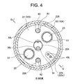
- FIG. 3 is a transverse sectional view (FIG. 2 (FIG. 7) BB sectional view) of the distal end portion of the ablation catheter shown in FIG.
- FIG. 6 is a transverse sectional view (DD sectional view of FIG. 2 (FIG. 7)) at the distal end portion of the ablation catheter shown in FIG. FIG.
- FIG. 8 is a transverse sectional view (AA sectional view of FIG. 2 (FIG. 7)) at the distal end portion of the ablation catheter shown in FIG.
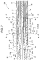
- FIG. 5 is a longitudinal sectional view (a sectional view taken along line FF in FIG. 3) at the distal end portion of the ablation catheter shown in FIG. 1. It is a perspective view which shows the irrigation member which comprises the ablation catheter shown in FIG. It is a perspective view which shows the irrigation member which comprises the ablation catheter shown in FIG.
- FIG. 5 is a longitudinal sectional view (GG sectional view of FIG. 4) at the distal end portion of the ablation catheter shown in FIG.
- FIG. 11 is a transverse cross-sectional view (HH cross-sectional view of FIG.
- FIG. 11 is a transverse sectional view (II sectional view of FIG. 10) at the distal end portion of the ablation catheter shown in FIG.
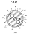
- FIG. 11 is a transverse sectional view (a sectional view taken along the line JJ in FIG. 10) at the distal end portion of the ablation catheter shown in FIG. 1.
- FIGS. 1 to 7 and FIGS. 10 to 13 is an ablation catheter of the present invention used for treatment of arrhythmia in the heart.
- the ablation catheter 100 of this embodiment has a distal end flexible portion 10A, and a catheter shaft 10 in which two lumens 11 and 11 serving as liquid flow paths are eccentrically formed in the distal end flexible portion 10A, and the catheter.
- An insulating irrigation member 20 connected to the distal end side of the shaft 10
- a distal electrode 30 connected to the distal end side of the irrigation member 20
- a ring electrode 40 mounted on the outer peripheral surface of the catheter shaft 10
- a catheter Tensile wires 61 and 62 constituting a deflection mechanism for deflecting the distal end flexible portion 10A of the shaft 10 and plates arranged along the central axis of the catheter shaft 10 and constituting the deflection mechanism together with the tension wires 61 and 62
- a spring 65, a control handle 70 connected to the proximal end side of the catheter shaft 10, and a liquid injection tube 80 Ete will;
- the distal end flexible portion 10A of the catheter shaft 10 is formed with two lumens 11 and 11 serving as liquid flow
- the irrigation member 20 has eight irrigation openings 25A for ejecting (irrigating) the liquid supplied from the catheter shaft 10 onto the surface of the tip electrode 30 along the outer periphery of the irrigation member 20 at an equiangular interval (45 °). Space) Inside the irrigation member 20, there are two eccentric flow passages 23, 23 communicating with the lumens 11, 11 serving as liquid flow passages of the catheter shaft 10, and a space communicating with the eccentric flow passages 23, 23.
- a liquid storage space 24 that does not have a partition wall in the circumferential direction and the storage space 24 are communicated and inclined outward.
- eight branch channels 25 extending in the distal direction and reaching each of the eight irrigation openings 25A are formed, and the tip of the irrigation member 20 is continuously connected to each of the eight branch channels 25.
- a liquid guide groove 26 extending in the distal direction from each of the irrigation openings 25A is formed;
- a liquid guide groove 36 is formed on the surface of the proximal end portion of the tip electrode 30 so as to be continuous with each of the guide grooves 26 of the irrigation member 20;
- the irrigation member 20 has a front-side recess 21A that can be fitted to the cylindrical portion 33 of the front-end electrode 30, and a recess 21B that is also formed on the rear-end side.
- a first small diameter portion 221 that can be fitted in the rear end concave portion 21B of the first component 21, and two eccentric flow paths 23, 23 are formed inside.
- the depth (d 21 ) of the rear end side recess 21B of the first component 21 is formed deeper than the length (d 22 ) of the distal end side small diameter portion 221 of the second component 22, thereby
- the storage space 24 (the bottom surface (rear end surface) 21b and the inner peripheral surface of the rear end recess 21B of the first component 21) and the front end surface of the front end side small diameter portion 221 of the second component 22 at the fitting part with the second component 22 22a) is formed.
- the ablation catheter 100 includes a catheter shaft 10 having a flexible tip portion 10A, an irrigation member 20, a tip electrode 30, a ring electrode 40, a control handle 70, and a liquid injection tube 80. And comprising.
- liquid 1 is connected to the catheter shaft 10 through the inside of the control handle 70, and the liquid is supplied to the lumen 11 of the catheter shaft 10 through the injection tube 80.
- liquid physiological saline can be exemplified.
- the control handle 70 shown in FIG. 1 is connected to the proximal end side of the catheter shaft 10 and includes a rotating plate 75 for performing a distal end deflection operation of the catheter.
- the catheter shaft 10 constituting the ablation catheter 100 has a flexible distal end portion 10A.
- the “tip flexible portion” refers to a tip portion of the catheter shaft that can be bent (bent) by pulling a wire for tip deflection operation.
- tension wires 61 and 62 for bending the tip flexible portion 10 ⁇ / b> A are disposed on the catheter shaft 10 (lumens 12 and 12).
- the rear ends of the tension wires 61 and 62 are connected to a rotating plate 75 (see FIG. 1) of the control handle 70, respectively.
- the front ends of the tension wires 61 and 62 are fixed on the outer peripheral surface (the storage groove 226) of the irrigation member 20 (second component 22). For example, when the rotating plate 75 is rotated in the A1 direction shown in FIG.
- the pulling wire 61 is pulled, and the distal end flexible portion 10A of the catheter shaft 10 is deflected in the arrow A direction and rotated in the B1 direction shown in FIG.
- the pulling wire 62 is pulled, and the distal end flexible portion 10A of the catheter shaft 10 is deflected in the arrow B direction.
- the distal end flexible portion 10 ⁇ / b> A of the catheter shaft 10 has the catheter shaft 10 on a plane perpendicular to the arrangement direction of the pulling wires 61 and 62 (the bending direction of the distal end flexible portion 10 ⁇ / b> A).
- a leaf spring 65 is disposed along the central axis.
- two lumens 11, 11 serving as liquid flow paths are formed on the distal flexible portion 10 ⁇ / b> A of the catheter shaft 10 so as to face each other across the central axis of the catheter shaft 10.
- the two lumens 11 and 11 in the distal end flexible portion 10A may merge at the shaft portion on the proximal end side with respect to the distal end flexible portion 10A.
- the distal end flexible portion 10A has two lumens 12 and 12 serving as insertion paths for the pulling wires 61 and 62, and a lead wire of the ring electrode 40 (not shown in FIG. 3).
- the distal flexible portion 10A of the catheter shaft 10 has a so-called multi-lumen structure.
- a distal end side concave portion having a single lumen structure is formed at the distal end of the catheter shaft 10 for joining with an irrigation member 20 described later.
- the catheter shaft 10 is made of a synthetic resin such as polyolefin, polyamide, polyether polyamide, polyurethane, nylon, or PEBAX (polyether block amide).
- the proximal end side of the catheter shaft 10 may be a blade tube obtained by braiding a tube made of these synthetic resins with a stainless steel wire.
- the outer diameter of the catheter shaft 10 is preferably 1.0 to 3.0 mm, more preferably 1.6 to 2.7 mm, and 2.36 mm as a suitable example.
- the length of the catheter shaft 10 is preferably 600 to 1500 mm, and more preferably 900 to 1200 mm.
- the ejection (irrigation) of the liquid onto the surface of the distal electrode 30 is performed by the irrigation member 20 located on the rear end side of the distal electrode 30.
- 8 and 9 are perspective views showing the shape of the irrigation member 20 constituting the ablation catheter 100.
- the irrigation member 20 is configured by fitting a first part 21 and a second part 22 together.
- the second component 22 constituting the irrigation member 20 is formed of a molded body in which a straight body portion 223 and a distal end side small diameter portion 221 having an outer diameter smaller than that of the straight body portion 223 are integrally formed. 8 and 9, the front end side small-diameter portion 221 of the second component 22 does not appear on the drawings because it is fitted inside the first component 21 (rear end side recess 21 ⁇ / b> B).
- the outer diameter of the straight body portion 223 of the second part 22 is preferably 0.80 to 2.80 mm, more preferably 1.80 to 2.12 mm, and 1.96 mm if a suitable example is shown.
- the outer diameter of the small-diameter portion 221 on the distal end side of the second component 22 is preferably 0.60 to 2.60 mm, more preferably 0.40 to 1.70 mm, and 1.45 mm if a suitable example is shown. .
- the second component 22 has a central through hole 224 formed along the central axis thereof, and the central axis on both sides of the central through hole 224.
- Eccentric flow paths 23, 23 extending in parallel with each other are formed.
- the central through-hole 224 and the eccentric flow paths 23 and 23 are through-holes extending from the front end surface 22a of the second component 22 (front end side small diameter portion 221) to the rear end surface 22b of the second component 22 (straight barrel portion 223).
- each of the openings of the eccentric flow paths 23 and 23 in the rear end surface 22b of the second part 22 is formed at the distal end surface (FIG. 3) of the catheter shaft 10. 2 opposite to each of the openings of the lumens 11 and 11 in the CC cross section of FIG.
- the lumens 11, 11 of the catheter shaft 10 and the eccentric flow paths 23, 23 of the irrigation member 20 (second part 22) communicate with each other via joint tubes 51, 51. Thereby, the connection between the catheter shaft 10 and the irrigation member 20 can be ensured, and the distal end surface of the catheter shaft 10 (the opening surface of the lumens 11 and 11) and the rear end surface of the irrigation member 20 are rear end surfaces. It is possible to prevent leakage of liquid at a contact point with 22b (opening surfaces of the eccentric flow paths 23, 23), and further, penetration of liquid into the shaft accompanying this.
- the cross-sectional shape of the eccentric flow passages 23, 23 penetrating through the second part 22 is from the inside of the straight body portion 223 to the distal end side small diameter portion 221.
- the shape changes from a circular shape to a substantially semicircular shape.
- the opening shape of the eccentric flow paths 23 and 23 on the rear end surface 22b of the second component 22 is circular, but the front end surface 22a of the second component 22 (FIG. 5)
- the thickness (for example, a thickness of 60 ⁇ m or more) of the molding material that defines the eccentric flow paths 23, 23 at the distal end side small diameter portion 221 is ensured. be able to.
- the housing grooves 226 and 226 for housing and fixing the distal end portions of the tension wires 61 and 62 are arranged on the outer peripheral surface of the second component 22 (the straight body portion 223). Is formed.
- a ring-shaped electrode 40 (first and second ring-shaped electrodes from the tip) is provided on the outer peripheral surface of the second component 22 (straight barrel portion 223).
- a storage groove 225 is formed to store the lead wire 40L.
- the storage groove 225 includes a shallow groove portion 225a, an inclined portion 225b, and a deep groove portion 225c from the front end toward the rear end.
- the width of the storage groove 225 is preferably 0.15 to 0.35 mm, and 0.26 mm as a suitable example.
- the depth of the shallow groove portion 225a of the storage groove 225 is preferably 0.10 to 0.20 mm, and 0.12 mm is a preferable example.
- the depth of the deep groove portion 225c of the storage groove 225 is preferably 0.15 to 0.65 mm, and 0.50 mm is shown as a suitable example.
- the first part 21 constituting the irrigation member 20 includes a straight body part 213, a large diameter part 212 having a larger outer diameter than the straight body part 213, and a reduced diameter part 211 that is reduced in diameter toward the distal end. It consists of a molded body formed in
- the outer diameter of the straight body portion 213 of the first component 21 is substantially the same as the outer diameter of the straight body portion 223 of the second component 22, and the outer diameter of the large diameter portion 212 is the same as the outer diameter of the catheter shaft 10. Substantially the same.
- the minimum outer diameter of the reduced diameter portion 211 of the first component 21 is substantially the same as the outer diameter of the neck portion 32 of the tip electrode 30.
- a distal end side recess 21 ⁇ / b> A that can be fitted to the rear end portion (cylindrical portion 33) of the distal electrode 30 is formed on the distal end side of the first component 21.
- a rear end side recess 21 ⁇ / b> B that can be fitted to the front end side small diameter portion 221 of the second component 22 is formed on the rear end side of the first component 21.
- the depth of the rear end side recess 21B of the first component 21 (indicated by d 21 in FIG. 7) is the second
- the tip 22 is formed deeper than the length (indicated by d 22 in FIG. 7) of the small diameter portion 221 on the tip side of the component 22.
- the first component 21 (the reduced diameter portion 211) has eight irrigation openings for injecting (irrigating) the liquid supplied from the catheter shaft 10 onto the surface of the tip electrode 30.
- 25A is arranged along the outer periphery of the irrigation member 20 at equiangular intervals (45 ° intervals).
- восем ⁇ branch flow paths 25 in the irrigation openings 25A extending in the distal direction while being inclined outward from the bottom surface (rear end surface) 21b of the rear end side recess 21B ( A through hole) is formed.
- the openings of the branch flow passage 25 in the bottom surface (rear end surface) 21 b of the rear end side recess 21 ⁇ / b> B are also arranged at equal angular intervals (45 ° intervals) along the circumferential direction of the irrigation member 20. ing.
- Each of the eight branch flow paths 25 is formed so as to be inclined outward (outside in the radial direction of the irrigation member 20) with respect to the axial direction of the irrigation member 20. Thereby, it is possible to sufficiently irrigate the surface of the tip electrode having a certain size.
- the inclination angle of the branch channel 25 is preferably 3 to 45 °, more preferably 5 to 13 °, and 7 ° as a suitable example.
- a liquid guide groove 26 is formed in the distal end portion (the reduced diameter portion 211) of the first component 21 so as to be continuous with each of the eight branch flow paths 25 and extend in the distal direction from each of the irrigation openings 25A. ing.
- the irrigation member 20 (first component 21) is provided with eight branch channels 25, irrigation openings 25A, and eight liquid guide grooves 26 along the outer periphery of the irrigation member 20 at intervals of 45 °. However, in FIG. 7 showing the longitudinal section, only a part of it is visible.
- the first component 21 extends from the bottom surface (rear end surface) 21b of the rear end side recess 21B to the bottom surface (front end surface 21a) of the front end side recess 21A.
- the central through hole 214 is formed along the central axis of the first component 21.
- the central through hole 214 of the first component 21 and the central through hole 224 of the second component 22 constitute a central through hole of the irrigation member 20.
- a central tube 54 is inserted into the central through hole (214, 224) of the irrigation member 20. Inside the central tube 54, the lead wire 30L of the tip electrode 30 and the lead wire 35L of the temperature sensor are inserted.
- the lead wire 40 ⁇ / b> L of the ring-shaped electrode 40 (first ring-shaped electrode from the tip) can be accommodated on the outer peripheral surface of the first component 21 (straight barrel portion 213).
- the two storage grooves 215 are arranged and formed at equal angular intervals (90 ° intervals) along the outer periphery of the straight body portion 213.
- the width of the storage groove 215 is preferably 0.12 to 0.50 mm, and is 0.34 mm as a suitable example.
- the depth of the storage groove 215 is preferably 0.10 to 0.20 mm, and 0.12 mm is shown as a suitable example.
- One of the four storage grooves 215 formed on the outer peripheral surface of the first component 21 is a storage groove 225 formed on the outer peripheral surface of the second component 22 (straight barrel portion 223).
- the lead wire 40L of the ring-shaped electrode 40 is housed in the housing groove 215 and the housing groove 225 of the second component 22. As shown in FIG.
- the lead wire 40L of the first ring electrode 40 from the tip passes through the storage groove 215 and the storage groove 225 (the shallow groove portion 225a, the inclined portion 225b, the deep groove portion 225c), and the catheter shaft 10 A connector (illustrated) is guided through the opening of the lumen 13 and enters the lumen 13 through the opening, passes through the lumen 13 of the catheter shaft 10 and the inside of the control handle 70, and is connected to the inside of the control handle 70 or the proximal end thereof. Is omitted).
- the lead wire 40L of the second ring-shaped electrode 40 from the tip is guided to the opening of the lumen 13 of the catheter shaft 10 through the storage groove 225 (shallow groove deep groove portion 225c).
- the catheter shaft in which the irrigation member is located is not formed until the storage groove (the storage groove 215 in the first component 21 and the storage groove 225 in the second component 22) of the lead wire 40L is formed on the outer peripheral surface of the irrigation member 20. It is possible to mount the ring-shaped electrode 40 on the outer peripheral surface (region) of 10. As a result, the distance between the tip electrode 30 and the first ring electrode 40 from the tip can be narrowed (for example, about 2 mm), and a desirable potential measurement can be performed between these electrodes. .
- the first component 21 and the second component 22 constituting the irrigation member 20 are made of a molded body of an insulating resin or an insulating ceramic.
- the first component 21 and the second component 22 are preferably made of a molded body obtained by a ceramic injection molding method (CIM). According to the ceramic injection molding method, even a fine shape (for example, a fine shape having a thickness of about 60 ⁇ m) that cannot be formed by resin injection molding can be formed.
- the irrigation member 20 can be reliably molded.
- the ceramic molding obtained by the ceramic injection molding method has low thermal conductivity suitable as a constituent material of the irrigation member.
- the ceramic molded body by the ceramic injection molding method is excellent in insulation, and even when the irrigation member 20 made of this molded body has an edge, current is concentrated on the edge portion when the ablation catheter 100 is used (cauterization). And does not become hot.
- a suitable ceramic material constituting the irrigation member 20 it is preferable to use zirconia from the viewpoint of excellent molding processability and excellent biocompatibility.
- the irrigation member 20 is configured by fitting a rear end side concave portion 21 ⁇ / b> B formed in the first component 21 and a front end side small diameter portion 221 of the second component 22.
- the bottom surface (rear end surface) 21b of the rear end side recess 21B of the first component 21 and the front end surface 22a of the second component 22 are separated by a distance of d 21 -d 22.
- a jacket space partitioned by the inner peripheral surface of the rear end side recess 21B and the outer peripheral surface of the central tube 54 is defined, and this jacket space serves as a liquid storage space 24.
- the storage space 24 formed in this way is a space for allowing the liquids from the eccentric flow paths 23, 23 to merge and uniformly distributing in the circumferential direction of the irrigation member 20. Since the storage space 24 has no circumferential partition, the liquid flowing into the storage space 24 can freely flow in the circumferential direction.
- the length (d 21 -d 22 ) of the storage space 24 is preferably 0.15 to 0.65 mm, and is 0.30 mm as a suitable example.
- the irrigation member 20 configured as described above has two eccentric flow paths 23 and 23 formed inside the second component 21 so as to communicate with the lumens 11 and 11 of the catheter shaft 10 serving as a liquid flow path. And the first component 21 and the second component 22 so that the liquid from the eccentric channels 23 and 23 is uniformly distributed in the circumferential direction of the irrigation member 20.
- a liquid storage space 24 that does not have a partition wall in the circumferential direction formed in the fitting portion of the, and communicates with the storage space 24 and extends in the distal direction while inclining outward to reach each of the irrigation openings 25A.
- the eight branch channels 25 formed inside the first component, and the tip portion (first component) extending in the distal direction from each of the irrigation openings 25A continuously to each of the eight branch channels 25. Liquid guide groove 2 formed in the reduced diameter portion 211) It comes to have.
- the straight part 213 and the second part 22 (the distal-side small diameter part 221 and the straight-body part 223) of the first part 21 constituting the irrigation member 20 are inserted into the distal-side concave part of the catheter shaft 10 ( And the eccentric flow paths 23 and 23 of the irrigation member 20 are communicated with the lumens 11 and 11 of the catheter shaft via the joint tubes 51 and 51, respectively.
- the irrigation member 20 is connected to. Thereby, only the reduced diameter portion 211 and the large diameter portion 212 of the first component 21 appear as the external shape of the irrigation member 20.
- the tip electrode 30 is connected to the tip side of the irrigation member 20 by fitting the cylindrical portion 33 of the tip electrode 30 into the tip side recess 21A of the irrigation member 20 (first component 21).
- the tip electrode 30 connected to the tip side of the irrigation member 20 and constituting the ablation catheter 100 has a hemispherical tip bulge portion 31, a neck portion 32, and a cylindrical portion 33.
- the diameter of the tip bulging portion 31 of the tip electrode 30 is preferably 1.0 to 3.3 mm, more preferably 2.2 to 2.6 mm, particularly preferably 2.3 to 2.5 mm.
- An example is 2.36 mm.
- D1 / D2 is too small, it is difficult to perform efficient cauterization treatment with a catheter provided with such a tip electrode.
- the value of D1 / D2 is excessive, it becomes difficult to irrigate a sufficient amount of liquid onto the surface of such a tip electrode.
- a liquid guide groove 36 that is continuous with each of the guide grooves 26 of the irrigation member 20 is formed at the proximal end portion (neck portion 32) of the distal electrode 30.
- the guide groove 36 By forming the guide groove 36, the liquid that has reached the proximal end portion of the distal electrode 30 through the guide groove 26 formed in the irrigation member 20 is guided (guided) to the distal end portion of the distal electrode 30. Accordingly, the liquid can be supplied to the entire surface of the tip electrode 30 including the tip bulge portion 31. Since the guide groove 36 formed in the tip electrode 30 has a gentle R shape, an abnormal temperature rise does not occur in this portion even during cauterization.
- the irrigation opening 25A is formed in the insulating irrigation member 20, and the conductive tip electrode 30 has no edge, so that the ablation catheter 100 is used (cautery).
- the ablation catheter 100 is used (cautery).
- a sufficient surface area for cauterization can be ensured, and efficient cauterization treatment can be performed.
- the liquid is ejected (irrigated) from the eight irrigation openings 25A arranged at the distal end portion of the irrigation member 20 onto the surface of the distal electrode 30.
- a sufficient amount of liquid can be brought into contact with the surface of the electrode 30.
- the liquid sprayed onto the surface of the tip electrode 30 flows along the surface of the tip electrode 30 from the base end portion (neck portion 32) of the tip electrode 30 toward the tip portion (tip bulge portion 31). . Therefore, the ablation catheter 100 has an excellent cooling effect on the surface of the tip electrode 30 and sufficient blood around the tip electrode 30 as compared with a conventionally known catheter in which an irrigation opening is formed in the tip electrode.
- the eight irrigation openings 25A are arranged at equiangular (45 °) intervals along the outer periphery of the irrigation member 20, it is possible to irrigate the surface of the tip electrode 30 over the entire region in the circumferential direction (360 °). it can.
- the two lumens 11, 11 serving as liquid flow paths, the two lumens 12, 12 serving as insertion paths for the pulling wires 61, 62, and the lead of the ring electrode 40 are provided. Since the two lumens 13 and 13 serving as line insertion passages are both formed at eccentric positions, a leaf spring 65 that could not be arranged by a conventional irrigation catheter having an irrigation member is attached to the catheter shaft. It becomes possible to arrange
- the ablation catheter 100 in which the leaf spring 65 is disposed is excellent in operability by providing sufficient torsional rigidity to the distal end flexible portion 10A of the catheter shaft 10.
- each of the eight branch channels 25 is ejected (irrigated) from the irrigation opening 25A, the amount of liquid supplied from the catheter shaft 10 to the irrigation member 20 varies in the circumferential direction (flexible tip portion).
- the irrigation member 20 is configured, and the cylindrical portion 33 of the tip electrode 30 (the rear end shape of the tip electrode) and the tip side recess 21A of the first component 21 (the tip shape of the first component) are fitted.
- irrigation member 2 The tip electrode 30 can be connected to the zero tip side.
- the irrigation member 20 by comprising the irrigation member 20 by two parts, the problem of the undercut resulting from the shape of the storage space 24 can be avoided, the eccentric flow paths 23 and 23, the storage space 24, and 8 It becomes possible to obtain the irrigation member 20 in which the branch channel 25 of the book is formed by molding.
- each of the branch flow paths 25 formed inside the irrigation member 20 (first component 11) is formed so as to be inclined outward, the tip electrode (D1 / D2 having a value of 1 / D2 having a certain size is 1).
- the surface of the tip electrode 30) which is 0.0 can be sufficiently irrigated.
- a liquid guide groove 26 extending in the distal direction continuously to each of the branch flow paths 25 is formed at the distal end portion of the irrigation member 20 (first component 11), so that it is ejected from the irrigation opening 25A.
- the liquid to be guided can be reliably guided (guided) toward the tip electrode 30.
- a liquid guide groove 36 that is continuous with each of the guide grooves 26 of the irrigation member 20 is formed on the surface of the proximal end portion of the tip electrode 30, so that it passes through the guide groove 26 formed in the irrigation member 20.
- the liquid that has reached the proximal end portion of the tip electrode 30 can be guided to the tip portion of the tip electrode 30, whereby the liquid can be supplied to the entire surface of the tip electrode 30.
- the number of branch channels (irrigation openings) in the irrigation member does not have to be 8, and can be appropriately selected within a range of 4 to 12, for example.
- the number of lumens (the number of eccentric flow paths in the irrigation member) serving as the liquid flow path of the catheter shaft may not be 2, but may be 1 or 3 or more.
- the present invention is effective when a catheter shaft having a small number of lumens serving as liquid channels is used.
- the internal structure of the catheter shaft is not particularly limited as long as the lumen serving as the liquid flow path is formed eccentrically at the distal end flexible portion.
- the shape of the tip electrode is not particularly limited, and may be a shell shape.
Landscapes
- Health & Medical Sciences (AREA)
- Life Sciences & Earth Sciences (AREA)
- Engineering & Computer Science (AREA)
- Surgery (AREA)
- Public Health (AREA)
- Animal Behavior & Ethology (AREA)
- Veterinary Medicine (AREA)
- General Health & Medical Sciences (AREA)
- Heart & Thoracic Surgery (AREA)
- Biomedical Technology (AREA)
- Otolaryngology (AREA)
- Medical Informatics (AREA)
- Molecular Biology (AREA)
- Nuclear Medicine, Radiotherapy & Molecular Imaging (AREA)
- Plasma & Fusion (AREA)
- Cardiology (AREA)
- Physics & Mathematics (AREA)
- Surgical Instruments (AREA)
- Media Introduction/Drainage Providing Device (AREA)
- Biophysics (AREA)
- Pulmonology (AREA)
- Anesthesiology (AREA)
- Hematology (AREA)
Abstract
La présente invention concerne un cathéter à électrode comprenant : une tige de cathéter (10) ayant une lumière formée de manière décentrée (11) et servant de passage pour le fluide, un élément d'irrigation (20), et une électrode d'extrémité (30) ; une pluralité de trous d'irrigation (25A) sont prévus sur l'élément d'irrigation à des intervalles équiangulaires ; un passage décentré (23) qui est raccordé à la lumière (11) de la tige (10), un espace de stockage (24) pour le liquide qui est raccordé au passage décentré (23) et n'a pas de paroi de séparation dans la direction périphérique, et une pluralité de passages de ramification (25) qui sont raccordés à l'espace de stockage (24), s'étendent dans la direction d'extrémité tout en s'inclinant vers l'extérieur, et arrivent au niveau de chacun des trous d'irrigation (25A) formés sur la section interne de l'élément d'irrigation (20) ; l'élément d'irrigation (20) comprend une première partie (21) et une seconde partie (22) ; le passage décentré (23) est formé sur la section interne de la seconde partie (22) ; et les passages de ramification (25) sont formés sur la section interne de la première partie (21) ; et l'espace de stockage (24) est formé dans la partie où la première partie (21) et la seconde partie (22) d'emboîtent. Ce cathéter à électrode rend possible l'irrigation uniforme de la surface de l'électrode d'extrémité (30) dans la direction périphérique en utilisant un liquide fourni par la lumière de la tige formée de manière décentrée (10).
Priority Applications (2)
| Application Number | Priority Date | Filing Date | Title |
|---|---|---|---|
| KR1020147016390A KR101758441B1 (ko) | 2011-12-09 | 2012-11-14 | 전극 카테터 |
| CN201280060310.1A CN103987335B (zh) | 2011-12-09 | 2012-11-14 | 电极导管 |
Applications Claiming Priority (2)
| Application Number | Priority Date | Filing Date | Title |
|---|---|---|---|
| JP2011-270140 | 2011-12-09 | ||
| JP2011270140A JP5881229B2 (ja) | 2011-12-09 | 2011-12-09 | 電極カテーテル |
Publications (1)
| Publication Number | Publication Date |
|---|---|
| WO2013084679A1 true WO2013084679A1 (fr) | 2013-06-13 |
Family
ID=48574057
Family Applications (1)
| Application Number | Title | Priority Date | Filing Date |
|---|---|---|---|
| PCT/JP2012/079569 Ceased WO2013084679A1 (fr) | 2011-12-09 | 2012-11-14 | Cathéter à électrode |
Country Status (4)
| Country | Link |
|---|---|
| JP (1) | JP5881229B2 (fr) |
| KR (1) | KR101758441B1 (fr) |
| CN (1) | CN103987335B (fr) |
| WO (1) | WO2013084679A1 (fr) |
Cited By (1)
| Publication number | Priority date | Publication date | Assignee | Title |
|---|---|---|---|---|
| US20230320780A1 (en) * | 2021-03-24 | 2023-10-12 | Japan Lifeline Co., Ltd. | Electrode catheter |
Families Citing this family (6)
| Publication number | Priority date | Publication date | Assignee | Title |
|---|---|---|---|---|
| CN105310766B (zh) * | 2014-07-17 | 2018-11-30 | 四川锦江电子科技有限公司 | 具有灌注液体功能的消融导管末端电极 |
| JP6456315B2 (ja) * | 2016-02-16 | 2019-01-23 | 日本ライフライン株式会社 | 電極カテーテル |
| US20220355071A1 (en) * | 2019-06-25 | 2022-11-10 | Kaneka Corporation | Catheter and method for producing the catheter |
| KR102415983B1 (ko) * | 2020-06-24 | 2022-07-04 | 권승열 | 동작 응답성을 향상시킨 복합 카테터 |
| JPWO2022162889A1 (fr) * | 2021-01-29 | 2022-08-04 | ||
| CN113616324A (zh) * | 2021-09-13 | 2021-11-09 | 心航路医学科技(广州)有限公司 | 矩阵型脉冲电场消融导管 |
Citations (5)
| Publication number | Priority date | Publication date | Assignee | Title |
|---|---|---|---|---|
| JPH09140801A (ja) * | 1995-11-21 | 1997-06-03 | Nippon Zeon Co Ltd | 電極カテーテル |
| JP2007181695A (ja) * | 2005-12-30 | 2007-07-19 | Biosense Webster Inc | チップ冷却が改善された切除カテーテル |
| WO2009082571A1 (fr) * | 2007-12-21 | 2009-07-02 | St. Jude Medical, Atrial Fibrillation Division, Inc. | Ensemble électrode d'ablation irrigué ayant une électrode polygonale |
| JP2009537243A (ja) * | 2006-05-16 | 2009-10-29 | セント・ジュード・メディカル・エイトリアル・フィブリレーション・ディヴィジョン・インコーポレーテッド | 温度の制御が改善されたアブレーション電極アセンブリおよび方法 |
| US8052684B2 (en) * | 2007-11-30 | 2011-11-08 | St. Jude Medical, Atrial Fibrillation Division, Inc. | Irrigated ablation catheter having parallel external flow and proximally tapered electrode |
Family Cites Families (4)
| Publication number | Priority date | Publication date | Assignee | Title |
|---|---|---|---|---|
| US8048070B2 (en) | 2000-03-06 | 2011-11-01 | Salient Surgical Technologies, Inc. | Fluid-assisted medical devices, systems and methods |
| US7210722B2 (en) * | 2005-01-25 | 2007-05-01 | International Truck Intellectual Property Company, Llc | Pull-out desk unit for mobile vehicle |
| WO2008045925A2 (fr) * | 2006-10-10 | 2008-04-17 | St. Jude Medical, Atrial Fibrillation Division, Inc. | Assemblage d'électrodes d'ablation avec sortie distale isolée |
| US9943363B2 (en) * | 2010-04-28 | 2018-04-17 | Biosense Webster, Inc. | Irrigated ablation catheter with improved fluid flow |
-
2011
- 2011-12-09 JP JP2011270140A patent/JP5881229B2/ja active Active
-
2012
- 2012-11-14 WO PCT/JP2012/079569 patent/WO2013084679A1/fr not_active Ceased
- 2012-11-14 KR KR1020147016390A patent/KR101758441B1/ko not_active Expired - Fee Related
- 2012-11-14 CN CN201280060310.1A patent/CN103987335B/zh not_active Expired - Fee Related
Patent Citations (5)
| Publication number | Priority date | Publication date | Assignee | Title |
|---|---|---|---|---|
| JPH09140801A (ja) * | 1995-11-21 | 1997-06-03 | Nippon Zeon Co Ltd | 電極カテーテル |
| JP2007181695A (ja) * | 2005-12-30 | 2007-07-19 | Biosense Webster Inc | チップ冷却が改善された切除カテーテル |
| JP2009537243A (ja) * | 2006-05-16 | 2009-10-29 | セント・ジュード・メディカル・エイトリアル・フィブリレーション・ディヴィジョン・インコーポレーテッド | 温度の制御が改善されたアブレーション電極アセンブリおよび方法 |
| US8052684B2 (en) * | 2007-11-30 | 2011-11-08 | St. Jude Medical, Atrial Fibrillation Division, Inc. | Irrigated ablation catheter having parallel external flow and proximally tapered electrode |
| WO2009082571A1 (fr) * | 2007-12-21 | 2009-07-02 | St. Jude Medical, Atrial Fibrillation Division, Inc. | Ensemble électrode d'ablation irrigué ayant une électrode polygonale |
Cited By (2)
| Publication number | Priority date | Publication date | Assignee | Title |
|---|---|---|---|---|
| US20230320780A1 (en) * | 2021-03-24 | 2023-10-12 | Japan Lifeline Co., Ltd. | Electrode catheter |
| US12508072B2 (en) * | 2021-03-24 | 2025-12-30 | Japan Lifeline Co., Ltd. | Electrode catheter |
Also Published As
| Publication number | Publication date |
|---|---|
| CN103987335B (zh) | 2016-06-08 |
| CN103987335A (zh) | 2014-08-13 |
| JP2013121384A (ja) | 2013-06-20 |
| KR101758441B1 (ko) | 2017-07-14 |
| JP5881229B2 (ja) | 2016-03-09 |
| KR20140102690A (ko) | 2014-08-22 |
Similar Documents
| Publication | Publication Date | Title |
|---|---|---|
| JP5881229B2 (ja) | 電極カテーテル | |
| JP5888783B2 (ja) | 電極カテーテル | |
| KR101830466B1 (ko) | 전극 카테터 | |
| JP5258005B1 (ja) | 電極カテーテル | |
| US11064929B2 (en) | Flexible electrode tip with halo irrigation | |
| JP2012176119A (ja) | 電極カテーテル | |
| JP5769303B2 (ja) | 電極カテーテル | |
| KR101649062B1 (ko) | 전극 카테터 | |
| JP5283135B2 (ja) | 電極カテーテル | |
| JP5867917B2 (ja) | 電極カテーテル | |
| US12508072B2 (en) | Electrode catheter | |
| HK1188917B (en) | Electrode catheters | |
| HK1171650B (en) | Electrode catheter |
Legal Events
| Date | Code | Title | Description |
|---|---|---|---|
| 121 | Ep: the epo has been informed by wipo that ep was designated in this application |
Ref document number: 12855247 Country of ref document: EP Kind code of ref document: A1 |
|
| NENP | Non-entry into the national phase |
Ref country code: DE |
|
| ENP | Entry into the national phase |
Ref document number: 20147016390 Country of ref document: KR Kind code of ref document: A |
|
| 122 | Ep: pct application non-entry in european phase |
Ref document number: 12855247 Country of ref document: EP Kind code of ref document: A1 |