WO2013087600A2 - Dispositif thermique destiné à la production d'énergie mécanique et/ou d'énergie électrique - Google Patents
Dispositif thermique destiné à la production d'énergie mécanique et/ou d'énergie électrique Download PDFInfo
- Publication number
- WO2013087600A2 WO2013087600A2 PCT/EP2012/075027 EP2012075027W WO2013087600A2 WO 2013087600 A2 WO2013087600 A2 WO 2013087600A2 EP 2012075027 W EP2012075027 W EP 2012075027W WO 2013087600 A2 WO2013087600 A2 WO 2013087600A2
- Authority
- WO
- WIPO (PCT)
- Prior art keywords
- working
- medium
- elements
- unit
- drive
- Prior art date
- Legal status (The legal status is an assumption and is not a legal conclusion. Google has not performed a legal analysis and makes no representation as to the accuracy of the status listed.)
- Ceased
Links
Images


Classifications
-
- F—MECHANICAL ENGINEERING; LIGHTING; HEATING; WEAPONS; BLASTING
- F03—MACHINES OR ENGINES FOR LIQUIDS; WIND, SPRING, OR WEIGHT MOTORS; PRODUCING MECHANICAL POWER OR A REACTIVE PROPULSIVE THRUST, NOT OTHERWISE PROVIDED FOR
- F03G—SPRING, WEIGHT, INERTIA OR LIKE MOTORS; MECHANICAL-POWER PRODUCING DEVICES OR MECHANISMS, NOT OTHERWISE PROVIDED FOR OR USING ENERGY SOURCES NOT OTHERWISE PROVIDED FOR
- F03G7/00—Mechanical-power-producing mechanisms, not otherwise provided for or using energy sources not otherwise provided for
- F03G7/06—Mechanical-power-producing mechanisms, not otherwise provided for or using energy sources not otherwise provided for using expansion or contraction of bodies due to heating, cooling, moistening, drying or the like
- F03G7/061—Mechanical-power-producing mechanisms, not otherwise provided for or using energy sources not otherwise provided for using expansion or contraction of bodies due to heating, cooling, moistening, drying or the like characterised by the actuating element
- F03G7/06112—Mechanical-power-producing mechanisms, not otherwise provided for or using energy sources not otherwise provided for using expansion or contraction of bodies due to heating, cooling, moistening, drying or the like characterised by the actuating element using the thermal expansion or contraction of enclosed fluids
- F03G7/06113—Mechanical-power-producing mechanisms, not otherwise provided for or using energy sources not otherwise provided for using expansion or contraction of bodies due to heating, cooling, moistening, drying or the like characterised by the actuating element using the thermal expansion or contraction of enclosed fluids the fluids subjected to phase change
-
- F—MECHANICAL ENGINEERING; LIGHTING; HEATING; WEAPONS; BLASTING
- F03—MACHINES OR ENGINES FOR LIQUIDS; WIND, SPRING, OR WEIGHT MOTORS; PRODUCING MECHANICAL POWER OR A REACTIVE PROPULSIVE THRUST, NOT OTHERWISE PROVIDED FOR
- F03G—SPRING, WEIGHT, INERTIA OR LIKE MOTORS; MECHANICAL-POWER PRODUCING DEVICES OR MECHANISMS, NOT OTHERWISE PROVIDED FOR OR USING ENERGY SOURCES NOT OTHERWISE PROVIDED FOR
- F03G7/00—Mechanical-power-producing mechanisms, not otherwise provided for or using energy sources not otherwise provided for
- F03G7/06—Mechanical-power-producing mechanisms, not otherwise provided for or using energy sources not otherwise provided for using expansion or contraction of bodies due to heating, cooling, moistening, drying or the like
- F03G7/064—Mechanical-power-producing mechanisms, not otherwise provided for or using energy sources not otherwise provided for using expansion or contraction of bodies due to heating, cooling, moistening, drying or the like characterised by its use
- F03G7/0641—Motors; Energy harvesting or waste energy recovery
-
- F—MECHANICAL ENGINEERING; LIGHTING; HEATING; WEAPONS; BLASTING
- F03—MACHINES OR ENGINES FOR LIQUIDS; WIND, SPRING, OR WEIGHT MOTORS; PRODUCING MECHANICAL POWER OR A REACTIVE PROPULSIVE THRUST, NOT OTHERWISE PROVIDED FOR
- F03G—SPRING, WEIGHT, INERTIA OR LIKE MOTORS; MECHANICAL-POWER PRODUCING DEVICES OR MECHANISMS, NOT OTHERWISE PROVIDED FOR OR USING ENERGY SOURCES NOT OTHERWISE PROVIDED FOR
- F03G7/00—Mechanical-power-producing mechanisms, not otherwise provided for or using energy sources not otherwise provided for
- F03G7/06—Mechanical-power-producing mechanisms, not otherwise provided for or using energy sources not otherwise provided for using expansion or contraction of bodies due to heating, cooling, moistening, drying or the like
- F03G7/066—Actuator control or monitoring
Definitions
- Thermal device for generating mechanical and / or electrical energy
- the present invention relates to a thermal device for generating mechanical and / or electrical energy by utilizing preferably naturally occurring temperature gradients, according to the preamble of claim 1.
- Object of the present invention is to provide a thermal device of the type mentioned, which leads in a simpler and more cost-effective manner to a substantially uninterrupted rotation of the acted upon by the working medium generator unit.
- the buffer storage unit at the end of a working stroke of each working element continuously receives the rotational movement of the generator unit in a simple manner even during the active change of temperature in the one or more working drive elements.
- the buffer storage unit according to the features of claim 2 membrane or spring storage, so that the receiving volume of the buffer memory can be adapted to the needs.
- the spring accumulator may contain mechanically formed springs or a compressible gas.
- the features of claim 3 are preferably provided for the buffer storage unit to adjust both for the flow and for the return of the working medium, the volumes in the buffer storage unit during the movement reversal in the working element.
- the features of claim 4 are provided.
- the temperature gradient and the temperature range of the working medium according to the features of claim 9 are selected.
- FIGS. 1 A first figure.
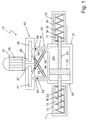
- FIG. 2 shows a schematic illustration of a thermal device for generating mechanical and / or electrical energy by utilizing preferably naturally existing temperature gradients according to a first exemplary embodiment of the present invention in two different working positions, FIG.
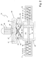
- FIG. 3 is a schematic longitudinal section of a thermal device for generating mechanical and / or electrical energy by utilizing preferably naturally existing temperature gradients with two drive elements according to a second exemplary embodiment of the present invention
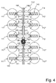
- Figure 4 is a plan view according to arrow IV of Figure 3 with more than two drive elements and
- FIG. 5 shows expansion-temperature diagrams of exemplary expansion media for devices according to FIGS. 1 to 4.
- thermal means 10 which serves to generate mechanical and / or electrical energy by utilizing preferably naturally existing temperature gradients, has a first drive element 11 and a second drive element 12, which operate in opposite directions movable and each one, for example cylindrical housing 13 and 14, which is filled with a temperature-dependent expansion medium 15, that is, a thermally expansive and thermally contraction medium 15.
- the expansive and contractive medium 15 or expansion medium 15 is a medium which achieves its greatest expansion or contraction during the phase transformation or during the phase transition from solid to liquid and vice versa.
- a temperature difference or a temperature gradient of, for example, about 10 ° C. is sufficient. It is understood that the temperature gradient can also be greater.
- the temperature range of the expansion medium may be between at least + 5 ° C and a maximum of + 45 ° C (see Figure 5).
- a working element 20 is provided between the first drive element 11 and the here diagonally opposite second drive element 12, which is provided with a cylinder in the form preferably of a hydraulic cylinder 21, in which a working member in the form of a piston 22 according to double arrow A back and forth is movable.
- the reciprocating working piston 22 is sealed on the outer peripheral side against the inner wall of the hydraulic cylinder 21, which is filled with a working fluid here in the form of a hydraulic fluid 25, for example hydraulic oil.
- the working piston 22 is connected in a motion-locking manner to a piston rod 23, which projects into the housing 14 or its expansion medium 15 with its one end 16 in the housing 13 or in its expansion medium 15 and its other end 17.
- the piston rod 23 penetrates the mutually facing end faces of hydraulic cylinder 21 and housing 13 and 14 movable and pressure-tight.
- the working piston 22 divides the hydraulic cylinder into two counter-volume volume changing hydraulic chambers 18 and 19th
- the receiving volume for the expansion medium 15 in the housing 13 and in the housing 14 of the first and second working element 11, 12 is the same size.
- the receiving volume for the hydraulic fluid 25 in the two chambers 18 and 19 of the hydraulic cylinder 21 of the working element 20 is greater, for example, twice the receiving volume for the expansion medium 15 of each of the two housings 13 and 14 of the first and second working element 11, 12th
- the working element 20 is connected to a generator unit 30 via a buffer memory unit 40.
- the generator unit 30 has a motor, here in the form of a hydraulic motor 29, on the output side either mechanical energy or electrical energy can be removed via a generator.
- the buffer memory unit 40 has two buffer chambers 41 and 42, which are spatially separated from each other and which are each connected via a connecting line 27 and 28 to the output or input of the hydraulic motor 29 of the generator unit 30.
- FIGS. 1 and 2 further show a flow direction controller 50 for the working medium 25 between the working element 20 and the buffer storage unit 40 and its buffer storage chambers 41 and 42, respectively.
- Both buffer storage chambers 41 and 42 are connected in each case via a first line 43 or 44 to the hydraulic chamber 18 located immediately below in the drawing or the hydraulic chamber 19 of the hydraulic cylinder 21 of the working element 20. Furthermore, the buffer chambers 41 and 42 are each connected via a second line 45 and 46 to the respective opposite hydraulic chamber 19 and 18 respectively. While the first lines 43, 44, for example, run approximately parallel, the two second lines 45, 46 are arranged approximately crosswise past each other. In all lines 43 to 46 are controlled valves or check valves 53, 54, 55 and 56, which open the lines 43 to 46 in one direction only because of the upcoming pressure of the working medium 25, as will be explained.
- the second drive element 12 is subjected to a higher temperature than the first drive element 11, the expansion medium 15 expands in the hermetically sealed housing 14 of the second drive element 12 and moves the end 17 of the piston rod 23 out of the hermetically sealed housing 14 (FIG. in Figure 1 according to arrow A to the left), so that the opposite end 16 of the piston rod 23 moves into the expansion medium 15 of the housing 13, as shown in Figure 1.
- the drive element 11 is cooled or must be cooled so that the expansion medium 15 contracts in the housing 13.
- the buffer chambers 41 and 42 are each designed as a diaphragm accumulator whose volumes can be increased and decreased by means of the membrane.
- This volume change of the buffer chambers 41, 42 is such that during the temperature change at which the pressure in front of the upstream side buffer chamber 42 decreases per se, is held by the diaphragm, the chamber pressure at a certain value, so still contained in the chamber hydraulic fluid 25 for Hydraulic motor 29 can continue to be promoted.
- heating or cooling elements in the form of coils 33 and 34, which are connected in a manner not shown with a heat supply device to each in the housing 13, 14th to heat or cool arranged expansion medium.
- thermal means 110 which serves to generate mechanical and / or electrical energy by utilizing preferably naturally existing temperature gradients, has at least two drive elements 111 and 112, which are preferably identical and within a respective, for example, cylindrical housing 113 or 114 with a temperature-dependent expansion medium 115, that is, a thermally expansive and thermally contractionous medium 115, are filled.
- the expansive and contractive medium 115 or expansion medium 115 is a medium which achieves its greatest expansion (in the range of approximately 10%, preferably 15% to 20%) or contraction in the phase transformation or in the phase transition from solid to liquid and vice versa.
- a temperature difference or a temperature gradient of, for example, about 10 ° C is sufficient.
- the temperature gradient can also be greater or less, preferably at about 8 ° C.
- the temperature range of the expansion medium can be between at least + 5 ° C and a maximum of + 45 ° C, preferably between 20 ° C and 25 ° C in the contraction state (1% expansion) and 27 ° C and 34 ° C in the expansion state (16% to 18 %) be.
- the aforementioned contraction or expansion states (min or max) are defined as the end points of the steepest curve region of the extent as a function of the temperature. This also applies to the first embodiment.
- the housing 113 or 114 standing upright here has a cylinder wall 116 which is closed by a cover-side and a bottom-side flange arrangement 117 or 118.
- a cylindrical insulation 119 is shown within the cylindrical wall 116 of the housing 114 of the drive element 112 .
- fin tubes 122 are provided which extend axially within the housing 114 and over a length range which is occupied by the expansion medium 115 in its most thermally expansive phase. It is understood that the housing 113 of the drive element 111 is formed in the same way and provided with insulation 119 and finned tubes 122.
- the drive element 111 or 112 is connected to a working element 120 or 121 via a pipeline 123 and 124, respectively.
- the working element 120 or 121 has an example cylindrical housing 126 or 127, in the bottom side of the pipeline 123 and 124 opens, which is the bottom-side flange 118 penetrating connected to the drive element 111 and 112, respectively.
- the working element 120 or 121 includes a hydraulic medium or a hydraulic fluid 125, which acts on a power generator unit 130 via a buffer memory unit 140. As can be seen from FIG. 1, both working elements 120 and 121 act on one and the same energy generator unit 130 via one and the same buffer unit 140.
- the liquid transfer medium 128 is contained in correspondingly different volumes in all movement phases of the expansion or contraction both in the drive element 111 or 112 and in the working element 120 or 121. It can be seen that this transfer medium 128 is used for the mechanical separation of expansion medium 115 and hydraulic medium 125, and so to speak as a reciprocating piston.
- the expansion medium 115 it is also possible to allow the expansion medium 115 to act directly on the hydraulic medium 125 or to form the transmission medium 128, in particular at high working pressures, as a mechanical piston made of metal or plastic.
- mechanical pistons it is possible to load the piston rod outside the working element 120, 121 in order to support the return or contraction movement, as well as to act on a stationary switch for position sensing and / or movement reversal.
- Both working elements 120 and 121 are connected via the buffer storage unit 140 with the generator unit 130, which has a motor, preferably in the form of a hydraulic motor 129, on the output either mechanical energy or electrical energy can be removed via a generator.
- a motor preferably in the form of a hydraulic motor 129
- the buffer storage unit 140 has two buffer storage chambers 141 and 142, which are spatially separated from each other and of which one 142 is associated with the hydraulic medium flow to the generator unit 130 and the other 141 the hydraulic fluid return from the generator unit 130.
- Each of these storage chambers 141 and 142 is formed as a spring storage chamber, that is within the storage chamber 141 and 142 is a piston 147, between which and a closed end 149 of the storage chamber 141 and 142, a mechanically or compressible gas formed as a compression spring 148 is arranged and which serves to change the receiving volume of the chamber 141, 142.
- the two buffer chambers 141 and 142 are flanged to a flow direction controller 150 and connected via a connecting line 137 or 138 to the input to and output from the hydraulic motor 129 of the generator unit 130.
- the flow direction control 150 for the working or hydraulic medium 125 which is evident in particular from FIG. 3, both from the working element 120 and from the working element 121, is designed such that the hydraulic motor 129 is connected both to the one working element 120 and to the other working element 121. It is possible to make a corresponding timing of the connection between the working element 120 or 121 and the hydraulic motor 129 of the generator unit 130.
- Both buffer chambers 141 and 142 are connected via a first line 143 and 144, respectively, to the hydraulic chamber 132, which is directly connected to it, in the housing 126 or 133 in the housing 127 of the working element 120 or 121. Furthermore, the buffer chambers 141 and 142 are each connected via a second line 145 and 146 with the respective opposite hydraulic chamber 133 and 132 of the respective other working element 120 and 121, respectively. While the first lines 143 and 144, for example, run approximately parallel, the two second lines 145, 146 are arranged approximately past each other passing over each other. In all lines 143 to 146 are controlled valves or check valves 153, 154, 155 and 156, which open the lines 143 to 146 in one direction only because of the upcoming pressure of the working medium 125, as will be explained.
- the expansion medium 115 expands in the hermetically sealed housing 114, which state is shown in FIG. 3, and moves the transmission medium 128 in the direction of the working element 121, so that the pressure exerted by the expansion medium 115 is increased transmits the hydraulic medium 125, which is pressed into the first conduit 144 and thereby opens the valve 154, so that the hydraulic fluid 125 is guided on the one hand into the hydraulic motor 129 to drive it and if necessary, if the hydraulic motor 129 can not absorb all the hydraulic fluid, is brought into the spring memory or the spring-loaded chamber 142 for buffering or temporary storage.
- the drive element 111 which is preferably supplied in a push-pull with positive or negative heat energy, so that as far as possible a smooth circulation of the hydraulic motor 129 is achieved.
- the expansion medium 115 in the drive element 111 is supplied with positive heat energy so that it can expand, by transmitting the pressure through the transfer medium 128 to the hydraulic medium 125 in the working element 120, the hydraulic medium through the second line 145 and after opening the valve 155 in this Line 145 is pressed on the one hand via the connecting line 137 in the hydraulic motor 129 and on the other hand at least partially brought into the storage chamber 142.
- the hydraulic medium 125 in the storage chamber 141 of the buffer storage unit 140 is at least partially stored before it can flow back into one of the working elements 120 and 121 due to the contraction of the relevant medium 115.
- FIG. 4 shows the embodiment of the thermal device 110 according to FIG. 1 as a thermal device 110 'with more than two drive elements 111, 112, 111' and 112 ', etc., whose media 115 are preferably heated or cooled at different times in that, in addition to the action of the buffer memory unit 140, to which all five drive element pairs 111/112 ?? 111 "" / 112 "" are connected, a synchronous or concentric run of the hydraulic motor 129 is ensured. All said drive element pairs are essentially identical and are each assigned to a buffer storage unit 140 or its flow direction controller 150 (not visible in FIG. 4) and to the single generator unit 130 via a common supply line 158 or return line 159. It is also possible to associate with each drive element pair a single buffer unit 140.
- heating or cooling elements in the form of pipe coils preferably lamellar pipe coils 122 are provided which are connected in a manner not shown with a heat supply device to heat or cool the respectively arranged in the housing expansion medium 115.
- the drive elements 111, 112, 111 ', 112' can either be staggered or simultaneously heated or cooled to achieve a continuously rotating movement of the hydraulic motor 129, in the latter case, the storage chambers 141, 142, etc. dimensioned accordingly and the valves 153 to 156 must be controlled.
Landscapes
- Engineering & Computer Science (AREA)
- Chemical & Material Sciences (AREA)
- Combustion & Propulsion (AREA)
- Mechanical Engineering (AREA)
- General Engineering & Computer Science (AREA)
- Engine Equipment That Uses Special Cycles (AREA)
- Fluid-Pressure Circuits (AREA)
Abstract
L'invention concerne un dispositif thermique (110) destiné à la production d'énergie mécanique et/ou d'énergie électrique par l'utilisation, de préférence, de gradients de température naturellement présents, ledit dispositif thermique comprenant au moins deux éléments d'entraînement (111, 112) qui contiennent respectivement un milieu d'expansion (115) fonction de la température, et qui sont respectivement reliés à un élément de travail (120) assurant l'entraînement d'une unité génératrice (130) d'énergie mécanique et/ou d'énergie électrique, chaque élément d'entraînement (111, 112) étant alternativement soumis à deux valeurs de température différentes. Une unité réservoir d'accumulation (140) destinée à un milieu de travail (125) prévu dans l'élément de travail (120, 121) étant disposée entre les éléments de travail (120, 121 ) et l'unité génératrice (130), tous les éléments d'entraînement p(111, 112) et tous les éléments de travail (120, 121) y reliés ayant en commun l'unité génératrice (130) et l'unité réservoir d'accumulation (140).
Applications Claiming Priority (4)
| Application Number | Priority Date | Filing Date | Title |
|---|---|---|---|
| DE102011088207A DE102011088207A1 (de) | 2011-12-12 | 2011-12-12 | Thermische Einrichtung zum Erzeugen von mechanischer und/oder elektrischer Energie |
| DE102011088207.3 | 2011-12-12 | ||
| DE102012211922.1 | 2012-07-09 | ||
| DE201210211922 DE102012211922A1 (de) | 2012-07-09 | 2012-07-09 | Thermische Einrichtung zum Erzeugen von mechanischer und/oder elektrischer Energie |
Publications (2)
| Publication Number | Publication Date |
|---|---|
| WO2013087600A2 true WO2013087600A2 (fr) | 2013-06-20 |
| WO2013087600A3 WO2013087600A3 (fr) | 2013-08-08 |
Family
ID=47594616
Family Applications (1)
| Application Number | Title | Priority Date | Filing Date |
|---|---|---|---|
| PCT/EP2012/075027 Ceased WO2013087600A2 (fr) | 2011-12-12 | 2012-12-11 | Dispositif thermique destiné à la production d'énergie mécanique et/ou d'énergie électrique |
Country Status (1)
| Country | Link |
|---|---|
| WO (1) | WO2013087600A2 (fr) |
Cited By (1)
| Publication number | Priority date | Publication date | Assignee | Title |
|---|---|---|---|---|
| DE102014214668A1 (de) | 2014-07-25 | 2016-01-28 | Erich Kumpf | Thermische Einrichtung zum Erzeugen von mechanischer und/oder elektrischer Energie |
Citations (2)
| Publication number | Priority date | Publication date | Assignee | Title |
|---|---|---|---|---|
| DE102008053781A1 (de) | 2008-10-23 | 2010-04-29 | Erich Kumpf | Einrichtung zum Erzeugen von mechanischer und/oder elektrischer Energie |
| DE102009055982A1 (de) | 2009-11-23 | 2011-05-26 | Erich Kumpf | Thermische Einrichtung zum Erzeugen von mechanischer und/oder elektrischer Energie |
Family Cites Families (5)
| Publication number | Priority date | Publication date | Assignee | Title |
|---|---|---|---|---|
| US3055170A (en) * | 1958-04-14 | 1962-09-25 | Cleveland Pneumatic Ind Inc | Liquid thermal engine |
| US3552120A (en) * | 1969-03-05 | 1971-01-05 | Research Corp | Stirling cycle type thermal device |
| FR2523221A1 (fr) * | 1982-03-11 | 1983-09-16 | Fraix Burnet Raymond | Procede et dispositif pour la production d'une energie directement utilisable a partir de deux sources de chaleur chaude et froide, situees dans une zone de temperature relativement basse |
| DE19719190C2 (de) * | 1997-05-08 | 1999-02-25 | Gerhard Stock | Warmwassermotor zur Wandlung von thermischer in elektrische Energie |
| AT502402B1 (de) * | 2006-01-10 | 2007-03-15 | Int Innovations Ltd | Verfahren zur umwandlung thermischer energie in mechanische arbeit |
-
2012
- 2012-12-11 WO PCT/EP2012/075027 patent/WO2013087600A2/fr not_active Ceased
Patent Citations (2)
| Publication number | Priority date | Publication date | Assignee | Title |
|---|---|---|---|---|
| DE102008053781A1 (de) | 2008-10-23 | 2010-04-29 | Erich Kumpf | Einrichtung zum Erzeugen von mechanischer und/oder elektrischer Energie |
| DE102009055982A1 (de) | 2009-11-23 | 2011-05-26 | Erich Kumpf | Thermische Einrichtung zum Erzeugen von mechanischer und/oder elektrischer Energie |
Cited By (1)
| Publication number | Priority date | Publication date | Assignee | Title |
|---|---|---|---|---|
| DE102014214668A1 (de) | 2014-07-25 | 2016-01-28 | Erich Kumpf | Thermische Einrichtung zum Erzeugen von mechanischer und/oder elektrischer Energie |
Also Published As
| Publication number | Publication date |
|---|---|
| WO2013087600A3 (fr) | 2013-08-08 |
Similar Documents
| Publication | Publication Date | Title |
|---|---|---|
| DE1933159A1 (de) | Waermevorrichtung der Stirling-Kreisprozess-Type | |
| DE1428008C3 (de) | Vorrichtung zum Verdichten bzw. Entspannen eines Mittels, die mit einer Regeleinrichtung zum Regeln der Größe des schädlichen Volumens versehen ist | |
| DE102009031904B4 (de) | Hydraulischer Antrieb | |
| EP3692261B1 (fr) | Système d'entraînement muni d'au moins un élément métallique présentant une caractéristique de mémoire de forme | |
| EP3490017A1 (fr) | Dispositif d'actionnement pourvu d'actionneur de corps fixe et d'unité hydraulique | |
| DE2631479A1 (de) | Arbeitskolbenvorrichtung | |
| DE1626401A1 (de) | Hydraulische Freikolbenpumpeinrichtung | |
| DE4320529A1 (de) | Verdichter | |
| DE102013224657A1 (de) | Hydraulische Anordnung | |
| DE1403973A1 (de) | Dosierungspumpe | |
| DE102012018029B4 (de) | Vorrichtung zum Temperieren mit einer piezoelektrisch angetriebenen Verdichtereinheit sowie Verfahren zur Regelung | |
| AT510434B1 (de) | Wärmekraftmaschine | |
| DE69004800T2 (de) | Regelbare verdrängerpumpe. | |
| WO2013087600A2 (fr) | Dispositif thermique destiné à la production d'énergie mécanique et/ou d'énergie électrique | |
| EP3956569B1 (fr) | Unité de transmission hydraulique pour un dispositif actionneur | |
| DE2153749B1 (de) | Absperreinrichtung fuer hydraulische speicher bei hydraulischen pruefmaschinen | |
| DE2341219A1 (de) | Durch ein medium angetriebene vibrierende vorrichtung | |
| DE102018203367A1 (de) | Hydrostatischer Linearantrieb | |
| DE102011088207A1 (de) | Thermische Einrichtung zum Erzeugen von mechanischer und/oder elektrischer Energie | |
| DE4030107A1 (de) | Hydraulischer stellantrieb fuer steuer- und regelarmaturen | |
| DE102010019670B4 (de) | Betätigungseinheit mit einem Aktor | |
| DE3939779A1 (de) | Verfahren und einrichtung zur umwandlung von waermeenergie in mechanische energie | |
| DE102012211922A1 (de) | Thermische Einrichtung zum Erzeugen von mechanischer und/oder elektrischer Energie | |
| DE102012107064A1 (de) | Heißgasmotor | |
| AT525551A4 (de) | Wärmekraftmaschine |
Legal Events
| Date | Code | Title | Description |
|---|---|---|---|
| 121 | Ep: the epo has been informed by wipo that ep was designated in this application |
Ref document number: 12816465 Country of ref document: EP Kind code of ref document: A2 |
|
| 32PN | Ep: public notification in the ep bulletin as address of the adressee cannot be established |
Free format text: FESTSTELLUNG EINES RECHTSVERLUSTS NACH REGEL 112(1) EPUE (EPA FORM 1205A VOM 02/10/2014) |
|
| 122 | Ep: pct application non-entry in european phase |
Ref document number: 12816465 Country of ref document: EP Kind code of ref document: A2 |