WO2013088497A1 - 電気車駆動システム - Google Patents
電気車駆動システム Download PDFInfo
- Publication number
- WO2013088497A1 WO2013088497A1 PCT/JP2011/078695 JP2011078695W WO2013088497A1 WO 2013088497 A1 WO2013088497 A1 WO 2013088497A1 JP 2011078695 W JP2011078695 W JP 2011078695W WO 2013088497 A1 WO2013088497 A1 WO 2013088497A1
- Authority
- WO
- WIPO (PCT)
- Prior art keywords
- electric vehicle
- circuit
- drive system
- resistor
- vehicle drive
- Prior art date
- Legal status (The legal status is an assumption and is not a legal conclusion. Google has not performed a legal analysis and makes no representation as to the accuracy of the status listed.)
- Ceased
Links
Images


Classifications
-
- B—PERFORMING OPERATIONS; TRANSPORTING
- B60—VEHICLES IN GENERAL
- B60L—PROPULSION OF ELECTRICALLY-PROPELLED VEHICLES; SUPPLYING ELECTRIC POWER FOR AUXILIARY EQUIPMENT OF ELECTRICALLY-PROPELLED VEHICLES; ELECTRODYNAMIC BRAKE SYSTEMS FOR VEHICLES IN GENERAL; MAGNETIC SUSPENSION OR LEVITATION FOR VEHICLES; MONITORING OPERATING VARIABLES OF ELECTRICALLY-PROPELLED VEHICLES; ELECTRIC SAFETY DEVICES FOR ELECTRICALLY-PROPELLED VEHICLES
- B60L1/00—Supplying electric power to auxiliary equipment of vehicles
- B60L1/006—Supplying electric power to auxiliary equipment of vehicles to power outlets
-
- B—PERFORMING OPERATIONS; TRANSPORTING
- B60—VEHICLES IN GENERAL
- B60L—PROPULSION OF ELECTRICALLY-PROPELLED VEHICLES; SUPPLYING ELECTRIC POWER FOR AUXILIARY EQUIPMENT OF ELECTRICALLY-PROPELLED VEHICLES; ELECTRODYNAMIC BRAKE SYSTEMS FOR VEHICLES IN GENERAL; MAGNETIC SUSPENSION OR LEVITATION FOR VEHICLES; MONITORING OPERATING VARIABLES OF ELECTRICALLY-PROPELLED VEHICLES; ELECTRIC SAFETY DEVICES FOR ELECTRICALLY-PROPELLED VEHICLES
- B60L3/00—Electric devices on electrically-propelled vehicles for safety purposes; Monitoring operating variables, e.g. speed, deceleration or energy consumption
-
- B—PERFORMING OPERATIONS; TRANSPORTING
- B60—VEHICLES IN GENERAL
- B60L—PROPULSION OF ELECTRICALLY-PROPELLED VEHICLES; SUPPLYING ELECTRIC POWER FOR AUXILIARY EQUIPMENT OF ELECTRICALLY-PROPELLED VEHICLES; ELECTRODYNAMIC BRAKE SYSTEMS FOR VEHICLES IN GENERAL; MAGNETIC SUSPENSION OR LEVITATION FOR VEHICLES; MONITORING OPERATING VARIABLES OF ELECTRICALLY-PROPELLED VEHICLES; ELECTRIC SAFETY DEVICES FOR ELECTRICALLY-PROPELLED VEHICLES
- B60L7/00—Electrodynamic brake systems for vehicles in general
- B60L7/02—Dynamic electric resistor braking
- B60L7/06—Dynamic electric resistor braking for vehicles propelled by AC motors
-
- B—PERFORMING OPERATIONS; TRANSPORTING
- B60—VEHICLES IN GENERAL
- B60L—PROPULSION OF ELECTRICALLY-PROPELLED VEHICLES; SUPPLYING ELECTRIC POWER FOR AUXILIARY EQUIPMENT OF ELECTRICALLY-PROPELLED VEHICLES; ELECTRODYNAMIC BRAKE SYSTEMS FOR VEHICLES IN GENERAL; MAGNETIC SUSPENSION OR LEVITATION FOR VEHICLES; MONITORING OPERATING VARIABLES OF ELECTRICALLY-PROPELLED VEHICLES; ELECTRIC SAFETY DEVICES FOR ELECTRICALLY-PROPELLED VEHICLES
- B60L9/00—Electric propulsion with power supply external to the vehicle
- B60L9/16—Electric propulsion with power supply external to the vehicle using AC induction motors
- B60L9/18—Electric propulsion with power supply external to the vehicle using AC induction motors fed from DC supply lines
- B60L9/22—Electric propulsion with power supply external to the vehicle using AC induction motors fed from DC supply lines polyphase motors
-
- H—ELECTRICITY
- H02—GENERATION; CONVERSION OR DISTRIBUTION OF ELECTRIC POWER
- H02P—CONTROL OR REGULATION OF ELECTRIC MOTORS, ELECTRIC GENERATORS OR DYNAMO-ELECTRIC CONVERTERS; CONTROLLING TRANSFORMERS, REACTORS OR CHOKE COILS
- H02P3/00—Arrangements for stopping or slowing electric motors, generators, or dynamo-electric converters
- H02P3/06—Arrangements for stopping or slowing electric motors, generators, or dynamo-electric converters for stopping or slowing an individual dynamo-electric motor or dynamo-electric converter
- H02P3/08—Arrangements for stopping or slowing electric motors, generators, or dynamo-electric converters for stopping or slowing an individual dynamo-electric motor or dynamo-electric converter for stopping or slowing a DC motor
- H02P3/12—Arrangements for stopping or slowing electric motors, generators, or dynamo-electric converters for stopping or slowing an individual dynamo-electric motor or dynamo-electric converter for stopping or slowing a DC motor by short-circuit or resistive braking
-
- H—ELECTRICITY
- H02—GENERATION; CONVERSION OR DISTRIBUTION OF ELECTRIC POWER
- H02P—CONTROL OR REGULATION OF ELECTRIC MOTORS, ELECTRIC GENERATORS OR DYNAMO-ELECTRIC CONVERTERS; CONTROLLING TRANSFORMERS, REACTORS OR CHOKE COILS
- H02P6/00—Arrangements for controlling synchronous motors or other dynamo-electric motors using electronic commutation dependent on the rotor position; Electronic commutators therefor
-
- B—PERFORMING OPERATIONS; TRANSPORTING
- B60—VEHICLES IN GENERAL
- B60L—PROPULSION OF ELECTRICALLY-PROPELLED VEHICLES; SUPPLYING ELECTRIC POWER FOR AUXILIARY EQUIPMENT OF ELECTRICALLY-PROPELLED VEHICLES; ELECTRODYNAMIC BRAKE SYSTEMS FOR VEHICLES IN GENERAL; MAGNETIC SUSPENSION OR LEVITATION FOR VEHICLES; MONITORING OPERATING VARIABLES OF ELECTRICALLY-PROPELLED VEHICLES; ELECTRIC SAFETY DEVICES FOR ELECTRICALLY-PROPELLED VEHICLES
- B60L2200/00—Type of vehicles
- B60L2200/26—Rail vehicles
Definitions
- the present invention relates to an electric vehicle drive system.
- the electric vehicle power converter operates with power supplied from the overhead line. Since the overhead line voltage is very high (for example, DC 1500 V), even if the power supply from the overhead line is cut off, a large amount of charge is accumulated in the filter capacitor in the main circuit. There is sex.
- the electric vehicle control device disclosed in Patent Document 1 below has a series circuit composed of a plurality of contactors and resistors connected between a converter and an inverter, and is used for inspection and maintenance of an electric vehicle.
- the contactor control unit discharges the charge of the filter capacitor through a resistor by putting a plurality of contactors into a predetermined time.
- the present invention has been made in view of the above, and it is an object of the present invention to provide an electric vehicle drive system capable of easily and reliably discharging a filter capacitor while suppressing an increase in circuit scale and circuit cost. Objective.
- the present invention converts a DC power or an AC power supplied from an overhead line into a desired AC power and drives a motor as a load to drive the electric vehicle.
- An electric vehicle drive system comprising: a first circuit breaker that interrupts a current flowing between the overhead wire and the electric vehicle power converter; and a ground switch that grounds the first circuit breaker.
- the electric vehicle power converter includes a smoothing circuit unit including a filter capacitor that receives and accumulates power supplied from the overhead wire, and converts a DC voltage of the smoothing circuit unit into an AC voltage to load.
- a main circuit unit including at least an inverter for driving the electric motor, and a second circuit breaker for cutting off a power supply path between the first circuit breaker and the inverter, and the ground switch Open more than 3 poles
- a single-throw type switch having a contact, and a predetermined resistor as one of circuit elements constituting the main circuit unit when the switching contact of the ground switch is closed is connected to the positive electrode of the filter capacitor It is connected to the switching contact of the ground switch so as to be electrically connected to the negative electrode.
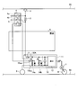
- FIG. 1 is a diagram illustrating a configuration of a main part of the electric vehicle drive system according to the first embodiment.
- FIG. 2 is a diagram illustrating a configuration of a main part of the electric vehicle drive system different from FIG. 1 according to the first embodiment.
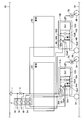
- FIG. 3 is a diagram illustrating a configuration of a main part of the electric vehicle drive system according to the second embodiment.
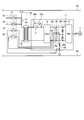
- FIG. 4 is a diagram illustrating a configuration of a main part of the electric vehicle drive system according to the third embodiment.
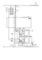
- FIG. 5 is a diagram illustrating a configuration of a main part of the electric vehicle drive system according to the fourth embodiment.
- FIG. 6 is a diagram illustrating a configuration of a main part of the electric vehicle drive system according to the fifth embodiment.
- FIG. 1 is a diagram showing a configuration of a main part of an electric vehicle drive system according to Embodiment 1 of the present invention.
- an electric vehicle drive system according to Embodiment 1 includes a pantograph 1, a high speed breaker (hereinafter referred to as “HB”) 2 as a first circuit breaker, and an earth as a ground switch.
- HB high speed breaker
- GSS Earth Ground Switch
- the electric vehicle power converter 11 includes a line breaker (hereinafter referred to as “LB”) 3 as a second circuit breaker 3 provided in the apparatus, a pantograph 1, HB 2, and LB 3 through an overhead line 50.
- a smoothing circuit unit 16 having a filter capacitor 16a for receiving and storing the DC power supplied from the inverter, and an inverter (hereinafter referred to as “INV") that converts the DC voltage of the smoothing circuit unit 16 into an AC voltage and drives the motor 7 as a load.
- a brake chopper (Brake CHopper: hereinafter referred to as “BCH”) circuit 14 that consumes surplus power that cannot be regenerated to the overhead wire 50 side when the motor 7 operates as a generator.
- the smoothing circuit unit 16, the INV 12, the BCH circuit 14 and the like constitute a main circuit unit of the electric vehicle power converter 11.
- the electric vehicle power converter 11 is mounted on the lower floor of the vehicle 6 as shown in the figure, for example, and the HB 2 and EGS 4 are mounted on the upper part of the vehicle 6 as shown in the figure. This is performed by using an outfitting wiring disposed in the vehicle 6.
- one end of the electric vehicle power converter 11 is connected to the overhead line 50 via the pantograph 1, HB2 and LB3, and the other end is connected to the rail 54 having the same potential as the ground potential via the wheel 9.
- the DC power supplied from the overhead line 50 is accumulated in the filter capacitor 16a and becomes the operating power of the INV 12.
- the INV 12 generates a desired AC power (AC voltage) and drives the motor 7 based on a control signal output from a control unit (not shown) (a signal for PWM controlling a switching element (not shown)).
- the electric motor 7 is connected to the wheel 8 and transmits driving force to the wheel 8.
- HB2 is a switch that cuts off the current flowing between the overhead wire 50 and the electric vehicle power converter 11.
- the EGS 4 is configured as a three-pole single-throw switch having the switching contact portions 4a, 4b, and 5, and is a switch controlled manually.
- the switching contacts 4a, 4b, 5 are conventional switching contacts, whereas the switching contact 5 is provided to solve the problems of the present invention. It is a switching contact part.
- One end of the switching contact portion 4a is connected to one end of the HB 2 (connection end on the pantograph 1 side), and the other end is grounded.
- One end of the switching contact portion 4b is connected to the other end of the HB 2 (connection end on the electric vehicle power converter 11 side), and the other end is grounded.
- one end of the switching contact portion 5 is connected to the positive DC bus 30A (which may be the same potential as the positive DC bus 30A) in the electric vehicle power converter 11, and the other end of the switching contact 5 is
- the BCH circuit 14 is connected to a connection end 32A between the switching element 15a and the brake resistor 15b.
- HB2 and LB3 are opened and the pantograph 1 is disconnected from the overhead line 50 at the time of inspection or maintenance of the electric vehicle.
- each contact of EGS 4 is closed by manual control.
- both ends of the HB 2 are grounded and become a ground potential.
- the conventional EGS does not have the switching contact portion 5, and the object is achieved by performing an operation in which both end portions of the HB 2 are grounded.
- the positive DC bus 30A and the connection end 32A between the switching element 15a and the brake resistor 15b are further electrically connected by the switching contact portion 5. .
- the positive electrode and the negative electrode of the filter capacitor 16a are electrically connected via the brake resistor 15b, so that a discharge circuit for discharging the accumulated charge of the filter capacitor 16a is formed.
- the accumulated charge in the filter capacitor 16a is discharged with a discharge curve according to a time constant determined by the product of the capacitance of the filter capacitor 16a and the resistance value of the brake resistor 15b.
- a discharge control circuit is separately configured as in Patent Document 1 described above, and a special control means is constructed to perform the discharge control. For this reason, in the conventional method, a circuit and control means for discharge control are separately required, and the circuit scale and circuit cost are increased.
- the electric vehicle drive system according to Embodiment 1 does not require a special control circuit and special control means for discharge control.
- the gist of the electric vehicle drive system according to the first embodiment is that the EGS configured as a two-pole single-throw switch is configured as a three-pole single-throw switch, and an additionally provided switching contact portion 5 is electrically connected to the BCH circuit 14 through the equipment wiring.
- the BCH circuit 14 is a circuit part provided in most electric vehicle power converters 11.
- the charge discharge of the filter capacitor 16a can be performed in conjunction with the EGS 3, so that no special operation for the charge discharge is necessary, and the burden on the operator is reduced. Can be reduced.
- the portion depending on the circuit operation is extremely small, the reliability related to charge discharge control can be improved, and the sense of security of the operator can be enhanced. can get.
- any one BCH circuit may be selected from a plurality of BCH circuits and connected to the switching contact portion 5.
- the BCH circuit 14a is selected from the two BCH circuits 14a and 14b, and one end of the switching contact portion 5 is connected to the positive DC bus 30A to which the BCH circuit 14a is connected. What is necessary is just to connect the other end of the switching contact part 5 to the connection end of the switching element 15aa and the brake resistor 15ba in the BCH circuit 14a.
- FIG. 3 is a diagram illustrating a configuration of a main part of the electric vehicle drive system according to the second embodiment.
- FIG. 3 shows a vehicle 6A equipped with the pantograph 1 and a vehicle 6B not equipped with the pantograph 1.
- Electric vehicle power conversion device 11A is mounted on vehicle 6A
- electric vehicle power conversion device 11B is mounted on vehicle 6B.
- the individual configurations of these electric vehicle power converters 11A and 11B and the connection configuration with the overhead wire 50 are the same as those in the first embodiment, and a part A related to the vehicle 6A is given a subscript A, Relevant parts are indicated with a suffix B.
- the EGS 4 is configured as a four-pole single-throw switch having the switching contact portions 4a, 4b, 5A, and 5B. That is, in the EGS 4 of the second embodiment, the switching contact portion 5B is added to the EGS 4 of the first embodiment.
- the switching contact portion 5A corresponds to the switching contact portion 5 in FIG. 1, and the connection destination is the same as in FIG. More specifically, one end of the switching contact portion 5A is connected to the positive DC bus 30A (or the same potential end as the positive DC bus 30A) in the electric vehicle power converter 11A. The end is connected to a connection end 32A between the switching element 15aA and the brake resistor 15bA in the BCH circuit 14A. On the other hand, one end of the switching contact 5B is connected to the positive DC bus 30B (or the same potential as the positive DC bus 30B) in the electric vehicle power converter 11B, and the other end of the switching contact 5B is BCH. The circuit 14B is connected to a connection end 32B between the switching element 15aB and the brake resistor 15bB.
- the contacts of the switching contacts 5A and 5B are simultaneously closed together with the contacts of the switching contacts 4a and 4b.
- the positive side DC bus 30A and the connection end 32A are electrically connected.
- the positive electrode and the negative electrode of the filter capacitor 16aA are electrically connected via the brake resistor 15bA, and the accumulated charge of the filter capacitor 16aA is quickly discharged.
- the positive side DC bus 30B and the connection end 32B are electrically connected.
- the positive electrode and the negative electrode of the filter capacitor 16aB are electrically connected via the brake resistor 15bB, and the accumulated charge of the filter capacitor 16aB is quickly discharged.
- the electric vehicle drive system according to Embodiment 2 also does not require a special control circuit for discharge control.
- the gist of the electric vehicle drive system according to the second embodiment is that the EGS configured as a two-pole single-throw switch is configured as at least a four-pole single-throw switch, and additionally provided switching contacts. This can be realized by electrically connecting the contacts of the sections 5A and 5B to the BCH circuits 14A and 14B through the equipment wiring, respectively.
- two additional switching contact portions are additionally provided in the EGS provided in the vehicle equipped with the pantograph, and one of them is the switching contact portion. Is electrically connected to the BCH circuit of the electric vehicle power converter mounted on the vehicle not equipped with the pantograph, so that the electric vehicle electric power is supplied to the vehicle not equipped with the pantograph. Even in the case where vehicles of a form in which conversion devices are mounted are mixed, the same effect as in the first embodiment can be obtained.
- FIG. 4 is a diagram illustrating a configuration of a main part of the electric vehicle drive system according to the third embodiment.
- the same or equivalent components as those in FIG. 1 are denoted by the same reference numerals, and redundant description is omitted.
- the charging circuit 22 is a circuit that controls charging of the filter capacitor 16a, and includes a charging resistor 22a and a contactor 22b for separating the charging circuit 22 from the circuit.
- the description relating to the operation is omitted.
- the EGS 4 according to the third embodiment is configured as a three-pole single-throw switch having switching contact portions 4a, 4b, and 5 as in the first embodiment.
- One end of the switching contact portion 5 is connected to the connection end 36 of the charging circuit 22 between the charging resistor 22a and the contactor 22b, and the other end of the switching contact portion 5 is grounded to the ground potential.
- connection end 36 between the charging resistor 22a and the contactor 22b is grounded to the ground potential.
- the positive electrode and the negative electrode of the filter capacitor 16a are electrically connected via the charging resistor 22a and the rail 54, and the accumulated charge in the filter capacitor 16a is quickly discharged.
- the electric vehicle drive system according to Embodiment 3 also does not require a special control circuit for discharge control.
- the gist of the electric vehicle drive system according to the third embodiment is that the EGS configured as a two-pole single-throw switch is configured as at least a three-pole single-throw switch, and additionally provided switching contacts. This can be realized by grounding one end of the part 5 and electrically connecting the other end of the switching contact part 5 to the charging resistor 22a through the fitting wiring.
- one additional switching contact portion is additionally provided in the EGS provided in the vehicle equipped with the pantograph, and one end of the switching contact portion is grounded. Since the other end is electrically connected to the charging resistor provided in the charging circuit in the apparatus, the same effect as in the case of using the BCH circuit described in the first embodiment can be obtained.
- an example of a mode in which an opening / closing contact part newly provided in EGS and a charging circuit of a power conversion device for an electric vehicle mounted on a vehicle equipped with a pantograph is electrically connected is electrically connected.
- the present invention can also be applied to a case where the electric vehicle power conversion device is mounted on a vehicle not equipped with a pantograph, as in the second embodiment.
- FIG. 5 is a diagram illustrating a configuration of a main part of the electric vehicle drive system according to the fourth embodiment.
- the same or equivalent components as those in FIG. 1 are denoted by the same reference numerals, and redundant description is omitted.
- a transformer 20 is provided on the input side of the electric vehicle power converter 11, and the electric vehicle power converter 11 has an AC voltage. Is applied. For this reason, the electric vehicle power converter 11 is provided with a converter (hereinafter referred to as “CNV”) 18 that converts the AC voltage stepped down by the transformer 20 into a DC voltage on the input side of the INV 12.
- CNV converter
- a low-side filter capacitor 16a and a high-side filter capacitor 16b are connected in series and connected between the DC buses.
- an overvoltage suppression circuit 26 in which a suppression thyristor 26a and an overvoltage suppression resistor 26b are connected in series is provided. Since the operation of the overvoltage suppression circuit 26 is publicly known, the description relating to the operation is omitted.
- the EGS 4 according to the fourth embodiment is configured as a four-pole single-throw switch having switching contact portions 4a, 4b, 5a, and 5b.
- the connection of the switching contact portions 4a and 4b is the same as in the first to third embodiments.
- one end of the switching contact portion 5a is connected to the negative side DC bus 40 (or the end having the same potential as the negative side DC bus 40), and the other end of the switching contact portion 5a is one end of the grounding resistor 28 (the ground side end). ).
- One end of the switching contact 5b is connected to the midpoint of the filter capacitors 16a and 16b (or the other end of the ground resistor 28), and the other end of the switching contact 5b is connected to the overvoltage suppression thyristor 26a in the overvoltage suppression circuit 26. It is connected to the connection end with the overvoltage suppression resistor 26b.
- the negative DC bus 40 and one end (ground side end) of the ground resistor 28 are electrically connected. Is done.
- the positive electrode and the negative electrode of the filter capacitor 16a which is the first filter capacitor, are electrically connected via the ground resistor 28, and the accumulated charge in the filter capacitor 16a is quickly discharged.
- the contact of the switching contact portion 5b is closed, the midpoint of the filter capacitors 16a and 16b and the connection end of the overvoltage suppression thyristor 26a and the overvoltage suppression resistor 26b are electrically connected.
- the positive electrode and the negative electrode of the filter capacitor 16b which is the second filter capacitor, are electrically connected via the overvoltage suppression resistor 26b, and the accumulated charge in the filter capacitor 16b is quickly discharged.
- the electric vehicle drive system according to Embodiment 4 also does not require a special control circuit for discharge control.
- the gist of the electric vehicle drive system according to the fourth embodiment is the first filter capacitor while the EGS configured as a two-pole single-throw switch is configured as at least a four-pole single-throw switch.
- the positive and negative electrodes of the filter capacitor 16b which is a second filter capacitor, are connected to the additional switching contact 5a provided so that the positive and negative electrodes of the filter capacitor 16a are electrically connected to both ends of the ground resistor 28.
- two additional switching contact portions are additionally provided in the EGS provided in the vehicle equipped with the pantograph, and one of the switching contact portions is provided.
- the positive and negative electrodes of the first filter capacitor are electrically connected to the ground resistance by the closing operation of the second filter capacitor, and the positive and negative electrodes of the second filter capacitor are overvoltaged by the closing operation of the other switching contact portion. Since it is configured to be electrically connected to the suppression resistor, even if the electric vehicle is an AC electric vehicle, the same effect as in the first embodiment can be obtained.
- the filter capacitor of the smoothing circuit unit is divided into the first and second filter capacitors has been described as an example, but the midpoint of the first and second filter capacitors is not grounded. If it is configured as a single filter capacitor, only one switching contact point may be added to the EGS. In this case, the positive and negative electrodes of the single filter capacitor are connected to ground resistance or overvoltage. What is necessary is just to comprise so that it may be connected to any one of the suppression resistors.
- FIG. 6 is a diagram illustrating a configuration of a main part of the electric vehicle drive system according to the fifth embodiment.
- the same or equivalent components as those in FIG. 1 are denoted by the same reference numerals, and redundant description is omitted.
- a three-level INV 12 a is provided as a converter that drives the electric motor 7.
- filter capacitors 16c and 16d are connected in series and connected between the DC buses.
- the BCH circuits 14c and 14d are connected in series and connected between the DC buses. Since the operation of the three-level INV 12a is known, the description relating to the operation is omitted.
- the EGS 4 according to the fifth embodiment is configured as a three-pole single-throw switch having switching contact portions 4a, 4b, and 5 as in the first embodiment.
- the connection of the switching contact portions 4a and 4b is the same as in the first to fourth embodiments.
- one end of the switching contact 5 is connected to the positive DC bus 30A (or the same potential as the positive DC bus 30A), and the other end of the switching contact 5 is switched in the BCH circuit 14c on the low side. It is connected to the connection end between the element 15ac and the brake resistor 15bc.
- the electric vehicle drive system according to Embodiment 5 also does not require a special control circuit for discharge control.
- the gist of the electric vehicle drive system according to the fifth embodiment is that the EGS configured as a two-pole single-throw switch is configured as at least a three-pole single-throw switch, and the positive electrode of the smoothing circuit unit 16 This can be realized by connecting to the switching contact portion 5 additionally provided so that the negative electrode is electrically connected to both ends of the brake resistor 15bc.
- one open / close contact portion is additionally provided in the EGS provided in the vehicle equipped with the pantograph, and smoothed by the closing operation of the open / close contact portion. Since the positive electrode and the negative electrode of the circuit unit are configured to be electrically connected to one of the brake resistors, the same configuration as in the first embodiment can be used even in a configuration using 3 level INV instead of 2 level INV. An effect can be obtained.
- the present invention is useful as an electric vehicle drive system that can easily and reliably discharge a filter capacitor.
Landscapes
- Engineering & Computer Science (AREA)
- Power Engineering (AREA)
- Transportation (AREA)
- Mechanical Engineering (AREA)
- Life Sciences & Earth Sciences (AREA)
- Sustainable Development (AREA)
- Sustainable Energy (AREA)
- Electric Propulsion And Braking For Vehicles (AREA)
Abstract
Description
図1は、本発明の実施の形態1に係る電気車駆動システムの主要部の構成を示す図である。実施の形態1に係る電気車駆動システムは、図示のように、パンタグラフ1、第1の遮断器としてのハイスピードブレーカ(High speed Breaker:以下「HB」と表記)2、接地開閉器としてのアースグラウンドスイッチ(Earth Ground Switch:以下「EGS」と表記)4、電気車用電力変換装置11および電動機7を備えて構成される。また、電気車用電力変換装置11は、この装置内に設けられる第2の遮断器としてのラインブレーカ(Line Breaker:以下「LB」と表記)3、パンタグラフ1、HB2およびLB3を介して架線50から供給される直流電力を受電して蓄積するフィルタコンデンサ16aを具備する平滑回路部16、平滑回路部16の直流電圧を交流電圧に変換して負荷である電動機7を駆動するインバータ(以下「INV」と表記)12および、電動機7が発電機として動作するときに架線50側に回生できない余剰電力を消費するブレーキチョッパ(Brake CHopper:以下「BCH」と表記)回路14を備えて構成される。なお、これら平滑回路部16、INV12、BCH回路14などは、電気車用電力変換装置11の主回路部を構成する。
実施の形態1では、パンタグラフを装備している車両に電気車用電力変換装置が搭載される場合を一例として示したが、実施の形態2では、パンタグラフを装備していない車両に電気車用電力変換装置が搭載される場合について、図3を参照して説明する。図3は、実施の形態2に係る電気車駆動システムの主要部の構成を示す図である。
実施の形態1では、EGSに新たに設けた開閉接点部と電気車用電力変換装置のBCH回路との間を電気的に接続する場合について説明したが、実施の形態3では、BCH回路以外の他の回路の一例として充電回路を用いる場合について、図4を参照して説明する。図4は、実施の形態3に係る電気車駆動システムの主要部の構成を示す図である。なお、図4において、図1と同一または同等の構成部については同一符号を付し、重複する説明については省略する。
実施の形態1~3では、電気車が直流電気車の場合について説明したが、実施の形態4では、電気車が交流電気車の場合の実施形態について、図5を参照して説明する。図5は、実施の形態4に係る電気車駆動システムの主要部の構成を示す図である。なお、図5において、図1と同一または同等の構成部については同一符号を付し、重複する説明については省略する。
実施の形態1~4では、電動機を駆動するINVが2レベルINVの場合について説明したが、実施の形態5では、電動機を駆動するINVが3レベルINVの場合について、図6を参照して説明する。図6は、実施の形態5に係る電気車駆動システムの主要部の構成を示す図である。なお、図6において、図1と同一または同等の構成部については同一符号を付し、重複する説明については省略する。
2 ハイスピードブレーカ(HB)
3 ラインブレーカ(LB)
4 アースグラウンドスイッチ(EGS)
4a,4b,5,5A,5B,5a,5b 開閉接点部
6,6A,6B 車両
7 電動機
8,9 車輪
11,11A,11B 電気車用電力変換装置
12 インバータ(INV)
12a 3レベルインバータ(3レベルINV)
14,14a~14d,14A,14B ブレーキチョッパ回路(BCH回路)
15a,15aa,15ac,15aA,15aB スイッチング素子
15b,15ba,15bc,15bA,15bB ブレーキ抵抗
16 平滑回路部
16a~16d,16aA,16aB フィルタコンデンサ
20 変圧器
21 リアクトル
22 充電回路
22a 充電抵抗
22b 接触器
26 過電圧抑制回路
26a 過電圧抑制サイリスタ
26b 過電圧抑制抵抗
28 接地抵抗
30A,30B 正側直流母線
40 負側直流母線
50 架線
54 レール
Claims (8)
- 架線から供給される直流電力または交流電力を所望の交流電力に変換して負荷である電動機を駆動する電気車用電力変換装置と、前記架線と前記電気車用電力変換装置との間に流れる電流を遮断する第1の遮断器と、この第1の遮断器を接地する接地開閉器と、を備えた電気車駆動システムであって、
前記電気車用電力変換装置には、前記架線からの供給電力を受電して蓄積するフィルタコンデンサを具備する平滑回路部と、この平滑回路部の直流電圧を交流電圧に変換して負荷である電動機を駆動するインバータと、を少なくとも含む主回路部と、第1の遮断器と前記インバータとの間の電力供給経路を遮断する第2の遮断器と、が設けられ、
前記接地開閉器は、3極以上の開閉接点を有する単投型の開閉器として構成され、
前記接地開閉器の開閉接点が閉路する際に前記主回路部を構成する回路要素の1つである所定の抵抗器が前記フィルタコンデンサの正極と負極との間に電気的に接続されるように前記接地開閉器の開閉接点に繋ぎ込まれていることを特徴とする電気車駆動システム。 - 前記主回路部は、前記電動機が発電機として動作するときに前記架線側に回生できない余剰電力を消費するブレーキチョッパ回路を有してなり、
前記所定の抵抗器として前記ブレーキチョッパ回路に具備されるブレーキ抵抗を用いることを特徴とする請求項1に記載の電気車駆動システム。 - 前記ブレーキチョッパ回路は、並列に接続される複数のブレーキチョッパ回路を有してなり、
前記所定の抵抗器として前記複数のブレーキチョッパ回路のうちの何れかのブレーキチョッパ回路に具備されるブレーキ抵抗を用いることを特徴とする請求項2に記載の電気車駆動システム。 - 前記主回路部は、前記フィルタコンデンサの充電を制御する充電回路を有してなり、
前記所定の抵抗器として前記充電回路に具備される充電抵抗を用いることを特徴とする請求項1に記載の電気車駆動システム。 - 前記電気車駆動システムは、交流架線からの供給電力を変圧器を介して受電して動作する駆動システムであり、
前記主回路部は、前記変圧器が降圧した交流電圧を直流電圧に変換するコンバータと、前記平滑回路部の過電圧を抑制する過電圧抑制回路と、を更に有してなり、
前記所定の抵抗器として前記過電圧抑制回路に具備される過電圧抑制抵抗を用いることを特徴とする請求項1に記載の電気車駆動システム。 - 前記電気車駆動システムは、交流架線からの供給電力を変圧器を介して受電して動作する駆動システムであり、
前記主回路部は、前記変圧器が降圧した交流電圧を直流電圧に変換するコンバータと、前記平滑回路部を構成し、直列接続される一方および他方のフィルタコンデンサ間の中点を接地する接地抵抗と、を更に有してなり、
前記所定の抵抗器として前記接地抵抗を用いることを特徴とする請求項1に記載の電気車駆動システム。 - 前記電気車駆動システムは、交流架線からの供給電力を変圧器を介して受電して動作する駆動システムであり、
前記主回路部は、前記変圧器が降圧した交流電圧を直流電圧に変換するコンバータと、前記平滑回路部の過電圧を抑制する過電圧抑制回路と、前記平滑回路部を構成し、直列接続されるローサイドおよびハイサイドのフィルタコンデンサ間の中点を接地する接地抵抗と、を更に有してなり、
前記所定の抵抗器の1つとして前記接地抵抗を用いることにより前記ローサイドのフィルタコンデンサに関する放電回路を形成し、且つ、前記所定の抵抗器の1つとして前記過電圧抑制回路に具備される過電圧抑制抵抗を用いることにより前記ハイサイドのフィルタコンデンサに関する放電回路を形成することを特徴とする請求項1に記載の電気車駆動システム。 - 前記主回路部のインバータは、3レベルインバータとして構成され、
前記主回路部の平滑回路部は、直列に接続されて直流母線間に接続されるローサイドおよびハイサイドのフィルタコンデンサを有して構成されると共に、
前記主回路部は、前記3レベルインバータの入力側にて前記ローサイドおよびハイサイドのフィルタコンデンサのそれぞれに並列に接続されるブレーキチョッパ回路を更に有してなり、
前記所定の抵抗器としてローサイドのフィルタコンデンサに具備されるブレーキ抵抗を用いると共に、前記ブレーキ抵抗における負側直流母線に接続されない側の端と正側直流母線の一端とを前記接地開閉器に繋ぎ込むことにより前記ローサイドおよびハイサイドのフィルタコンデンサに関する放電回路を形成することを特徴とする請求項1に記載の電気車駆動システム。
Priority Applications (7)
| Application Number | Priority Date | Filing Date | Title |
|---|---|---|---|
| JP2013548974A JP5638704B2 (ja) | 2011-12-12 | 2011-12-12 | 電気車駆動システム |
| EP11877372.0A EP2792530B1 (en) | 2011-12-12 | 2011-12-12 | Electric vehicle drive system |
| PCT/JP2011/078695 WO2013088497A1 (ja) | 2011-12-12 | 2011-12-12 | 電気車駆動システム |
| KR1020147017518A KR101591218B1 (ko) | 2011-12-12 | 2011-12-12 | 전기차 구동 시스템 |
| CN201180075417.9A CN103987561B (zh) | 2011-12-12 | 2011-12-12 | 电动车驱动系统 |
| US14/364,231 US9225268B2 (en) | 2011-12-12 | 2011-12-12 | Electric vehicle drive system |
| ES11877372.0T ES2600510T3 (es) | 2011-12-12 | 2011-12-12 | Sistema de impulsión de vehículo eléctrico |
Applications Claiming Priority (1)
| Application Number | Priority Date | Filing Date | Title |
|---|---|---|---|
| PCT/JP2011/078695 WO2013088497A1 (ja) | 2011-12-12 | 2011-12-12 | 電気車駆動システム |
Publications (1)
| Publication Number | Publication Date |
|---|---|
| WO2013088497A1 true WO2013088497A1 (ja) | 2013-06-20 |
Family
ID=48611986
Family Applications (1)
| Application Number | Title | Priority Date | Filing Date |
|---|---|---|---|
| PCT/JP2011/078695 Ceased WO2013088497A1 (ja) | 2011-12-12 | 2011-12-12 | 電気車駆動システム |
Country Status (7)
| Country | Link |
|---|---|
| US (1) | US9225268B2 (ja) |
| EP (1) | EP2792530B1 (ja) |
| JP (1) | JP5638704B2 (ja) |
| KR (1) | KR101591218B1 (ja) |
| CN (1) | CN103987561B (ja) |
| ES (1) | ES2600510T3 (ja) |
| WO (1) | WO2013088497A1 (ja) |
Cited By (3)
| Publication number | Priority date | Publication date | Assignee | Title |
|---|---|---|---|---|
| RU201878U1 (ru) * | 2020-08-13 | 2021-01-19 | Общество с ограниченной ответственностью "Уральские локомотивы" | Силовая электрическая схема электропоезда постоянного тока |
| JP2022190949A (ja) * | 2021-06-15 | 2022-12-27 | 株式会社日立製作所 | 鉄道車両用の駆動システムおよび該駆動システムの設置方法 |
| JPWO2024047841A1 (ja) * | 2022-09-01 | 2024-03-07 |
Families Citing this family (18)
| Publication number | Priority date | Publication date | Assignee | Title |
|---|---|---|---|---|
| CN105235536B (zh) * | 2015-11-04 | 2017-11-28 | 株洲中车时代电气股份有限公司 | 一种动车组牵引系统及能量控制方法 |
| US11056298B2 (en) * | 2018-07-13 | 2021-07-06 | Ge Energy Power Conversion Technology Limited | Earthing switch having dynamic braking resistors |
| RU184899U1 (ru) * | 2018-07-30 | 2018-11-13 | Общество с ограниченной ответственностью "Уральские локомотивы" | Силовая электрическая схема электропоезда |
| RU184898U1 (ru) * | 2018-07-30 | 2018-11-13 | Общество с ограниченной ответственностью "Уральские локомотивы" | Силовая электрическая схема электропоезда постоянного тока |
| RU186433U1 (ru) * | 2018-08-31 | 2019-01-21 | Общество с ограниченной ответственностью "Уральские локомотивы" | Силовая электрическая схема электропоезда |
| RU186451U1 (ru) * | 2018-08-31 | 2019-01-21 | Общество с ограниченной ответственностью "Уральские локомотивы" | Силовая электрическая схема электропоезда постоянного тока с отсасывающим фильтром высокочастотных помех |
| DE102018221741B4 (de) | 2018-12-14 | 2020-06-25 | Volkswagen Aktiengesellschaft | System für elektrisch straßengebundene Fahrzeuge |
| US11482890B2 (en) | 2020-04-30 | 2022-10-25 | Nucurrent, Inc. | Surface mountable wireless power transmitter for transmission at extended range |
| DE102020215604A1 (de) * | 2020-12-10 | 2022-06-15 | Robert Bosch Gesellschaft mit beschränkter Haftung | Ansteuerschaltung für eine elektrische Maschine, elektrisches Antriebssystem und Verfahren zum Abbremsen einer elektrischen Maschine |
| US11476711B2 (en) | 2020-12-23 | 2022-10-18 | Nucurrent, Inc. | Wireless power transmitters and associated base stations for through-structure charging |
| US11637459B2 (en) | 2020-12-23 | 2023-04-25 | Nucurrent, Inc. | Wireless power transmitters for transmitting power at extended separation distances utilizing T-Core shielding |
| US11387684B1 (en) | 2020-12-23 | 2022-07-12 | Nucurrent, Inc. | Wireless power transmitters and associated base stations for transmitting power at extended separation distances |
| US11387674B1 (en) | 2020-12-23 | 2022-07-12 | Nucurrent, Inc. | Wireless power transmitters for transmitting power at extended separation distances utilizing concave shielding |
| US11757311B2 (en) | 2020-12-23 | 2023-09-12 | Nucurrent, Inc. | Wireless power transmitters and associated base stations for transmitting power at extended separation distances |
| US11637448B1 (en) * | 2021-10-12 | 2023-04-25 | Nucurrent, Inc. | Wireless power transmitter with removable magnetic connector panel for vehicular use |
| US12132325B2 (en) | 2021-10-12 | 2024-10-29 | Nucurrent, Inc. | Wireless power transmitter with removable magnetic connector panel |
| US11967830B2 (en) | 2021-10-12 | 2024-04-23 | Nucurrent, Inc. | Wireless power transmitters for transmitting power at extended separation distances with magnetic connectors |
| EP4526149A1 (de) * | 2022-07-18 | 2025-03-26 | Siemens Mobility GmbH | Multikontakt-erdungstrenner für ein schienenfahrzeug |
Citations (3)
| Publication number | Priority date | Publication date | Assignee | Title |
|---|---|---|---|---|
| JPH0819101A (ja) | 1994-07-01 | 1996-01-19 | Toshiba Corp | 電気車の制御装置 |
| JPH08331870A (ja) * | 1995-05-30 | 1996-12-13 | Shinko Electric Co Ltd | 回生機能付き正弦波コンバータにおける主回路コンデンサの放電回路 |
| WO2007122671A1 (ja) * | 2006-04-12 | 2007-11-01 | Mitsubishi Denki Kabushiki Kaisha | 電気車の制御装置 |
Family Cites Families (12)
| Publication number | Priority date | Publication date | Assignee | Title |
|---|---|---|---|---|
| JPH02106101A (ja) * | 1988-10-14 | 1990-04-18 | Mitsubishi Electric Corp | 電気車の制御装置 |
| JPH04207986A (ja) | 1990-11-30 | 1992-07-29 | Hitachi Ltd | インバータ装置 |
| JPH05252755A (ja) | 1992-03-02 | 1993-09-28 | Mitsubishi Electric Corp | インバータ制御回路 |
| JPH0937562A (ja) | 1995-07-17 | 1997-02-07 | Mitsubishi Electric Corp | インバータ装置 |
| DE19931199A1 (de) * | 1999-07-07 | 2001-01-18 | Daimler Chrysler Ag | Verfahren zur Steuerung eines Leistungs-Antriebssystems |
| JP2001037004A (ja) | 1999-07-26 | 2001-02-09 | Hitachi Ltd | インバータ式電気車制御装置 |
| JP2004056956A (ja) | 2002-07-23 | 2004-02-19 | Toshiba Corp | フィルタコンデンサ容量低下検知回路 |
| FR2920356B1 (fr) * | 2007-09-04 | 2012-05-18 | Alstom Transport Sa | Dispositif securitaire de detection d'insufisance de freinage electrique et de commutation sur un frein securitaire. |
| DE102008014571A1 (de) * | 2008-03-13 | 2009-09-17 | Siemens Aktiengesellschaft | Motoransteuerschaltung für ein Schienenfahrzeug und Verfahren zu deren Betrieb |
| CN102196938B (zh) * | 2008-10-23 | 2014-04-23 | 三菱电机株式会社 | 电车的推进控制装置 |
| DE102009008549A1 (de) * | 2009-02-12 | 2010-08-19 | Bombardier Transportation Gmbh | Anordnung zum Betreiben von Verbrauchern in einem Schienenfahrzeug mit elektrischer Energie, wahlweise aus einem Energieversorgungsnetz oder aus einer Motor-Generator-Kombination |
| JP5268765B2 (ja) * | 2009-04-23 | 2013-08-21 | 株式会社東芝 | 電気車制御装置 |
-
2011
- 2011-12-12 EP EP11877372.0A patent/EP2792530B1/en active Active
- 2011-12-12 KR KR1020147017518A patent/KR101591218B1/ko not_active Expired - Fee Related
- 2011-12-12 WO PCT/JP2011/078695 patent/WO2013088497A1/ja not_active Ceased
- 2011-12-12 JP JP2013548974A patent/JP5638704B2/ja not_active Expired - Fee Related
- 2011-12-12 ES ES11877372.0T patent/ES2600510T3/es active Active
- 2011-12-12 US US14/364,231 patent/US9225268B2/en active Active
- 2011-12-12 CN CN201180075417.9A patent/CN103987561B/zh active Active
Patent Citations (3)
| Publication number | Priority date | Publication date | Assignee | Title |
|---|---|---|---|---|
| JPH0819101A (ja) | 1994-07-01 | 1996-01-19 | Toshiba Corp | 電気車の制御装置 |
| JPH08331870A (ja) * | 1995-05-30 | 1996-12-13 | Shinko Electric Co Ltd | 回生機能付き正弦波コンバータにおける主回路コンデンサの放電回路 |
| WO2007122671A1 (ja) * | 2006-04-12 | 2007-11-01 | Mitsubishi Denki Kabushiki Kaisha | 電気車の制御装置 |
Non-Patent Citations (1)
| Title |
|---|
| See also references of EP2792530A4 |
Cited By (5)
| Publication number | Priority date | Publication date | Assignee | Title |
|---|---|---|---|---|
| RU201878U1 (ru) * | 2020-08-13 | 2021-01-19 | Общество с ограниченной ответственностью "Уральские локомотивы" | Силовая электрическая схема электропоезда постоянного тока |
| JP2022190949A (ja) * | 2021-06-15 | 2022-12-27 | 株式会社日立製作所 | 鉄道車両用の駆動システムおよび該駆動システムの設置方法 |
| JP7637573B2 (ja) | 2021-06-15 | 2025-02-28 | 株式会社日立製作所 | 鉄道車両用の駆動システムおよび該駆動システムの設置方法 |
| JPWO2024047841A1 (ja) * | 2022-09-01 | 2024-03-07 | ||
| JP7552930B2 (ja) | 2022-09-01 | 2024-09-18 | 株式会社Tmeic | 電力変換システム |
Also Published As
| Publication number | Publication date |
|---|---|
| KR101591218B1 (ko) | 2016-02-02 |
| EP2792530A4 (en) | 2015-10-21 |
| US9225268B2 (en) | 2015-12-29 |
| CN103987561A (zh) | 2014-08-13 |
| JP5638704B2 (ja) | 2014-12-10 |
| KR20140102257A (ko) | 2014-08-21 |
| JPWO2013088497A1 (ja) | 2015-04-27 |
| EP2792530B1 (en) | 2016-09-28 |
| CN103987561B (zh) | 2016-05-04 |
| EP2792530A1 (en) | 2014-10-22 |
| US20140368134A1 (en) | 2014-12-18 |
| ES2600510T3 (es) | 2017-02-09 |
Similar Documents
| Publication | Publication Date | Title |
|---|---|---|
| JP5638704B2 (ja) | 電気車駆動システム | |
| CN101888939B (zh) | 用于限制接通电流以及用于对直流电压中间电路进行放电的方法和装置 | |
| JP5819022B2 (ja) | 鉄道車両の推進制御装置 | |
| US5170105A (en) | Method for determining operability of an electrical dynamic braking system | |
| US6755267B2 (en) | Electric vehicle and control device thereof | |
| CN102754346A (zh) | 用于隔离开关的开关去负荷 | |
| CN113015663B (zh) | 再生制动系统、及使用该系统的电力驱动作业车辆 | |
| US9774215B2 (en) | Power conversion apparatus | |
| US20180198365A1 (en) | Low-Voltage Discharge and Actuation Circuit for the Traction Converter of a Vehicle | |
| CN106797173A (zh) | 具有冗余的开关熔融保险装置组合的变流器和用于在开关失效情况下选择性地触发保险装置的方法 | |
| CN103248040A (zh) | 用于使电网的中间电路放电的方法和装置 | |
| JP4738479B2 (ja) | 電気車の制御装置 | |
| CN109982888B (zh) | 铁路车辆用电路系统 | |
| JP5875884B2 (ja) | 電気車制御装置 | |
| JP2017055500A (ja) | 鉄道車両の制御システム及び制御方法 | |
| EP2644436B1 (en) | Improved hard pre-charge for parallel inverters | |
| KR102493181B1 (ko) | 전류 경로의 직류를 차단하기 위한, 그리고 자동차의 온-보드 전기 시스템을 위한 연결해제 디바이스 | |
| US7505236B2 (en) | Arc suppression circuit | |
| WO2013021437A1 (ja) | 駆動制御装置 | |
| JP6642974B2 (ja) | 電気車制御装置 | |
| JP7460508B2 (ja) | 電力変換装置 | |
| JP2010220444A (ja) | 永久磁石モータドライブ装置 | |
| JP2011151879A (ja) | モータ制御装置 | |
| JP2018191487A (ja) | 車両用制御装置 | |
| WO2021205586A1 (ja) | 電力変換装置 |
Legal Events
| Date | Code | Title | Description |
|---|---|---|---|
| WWE | Wipo information: entry into national phase |
Ref document number: 201180075417.9 Country of ref document: CN |
|
| 121 | Ep: the epo has been informed by wipo that ep was designated in this application |
Ref document number: 11877372 Country of ref document: EP Kind code of ref document: A1 |
|
| ENP | Entry into the national phase |
Ref document number: 2013548974 Country of ref document: JP Kind code of ref document: A |
|
| NENP | Non-entry into the national phase |
Ref country code: DE |
|
| ENP | Entry into the national phase |
Ref document number: 20147017518 Country of ref document: KR Kind code of ref document: A |
|
| WWE | Wipo information: entry into national phase |
Ref document number: 14364231 Country of ref document: US |
|
| REEP | Request for entry into the european phase |
Ref document number: 2011877372 Country of ref document: EP |
|
| WWE | Wipo information: entry into national phase |
Ref document number: 2011877372 Country of ref document: EP |