WO2013089009A1 - Dispositif de coupe - Google Patents
Dispositif de coupe Download PDFInfo
- Publication number
- WO2013089009A1 WO2013089009A1 PCT/JP2012/081598 JP2012081598W WO2013089009A1 WO 2013089009 A1 WO2013089009 A1 WO 2013089009A1 JP 2012081598 W JP2012081598 W JP 2012081598W WO 2013089009 A1 WO2013089009 A1 WO 2013089009A1
- Authority
- WO
- WIPO (PCT)
- Prior art keywords
- trim
- block
- cutter blade
- cutter
- roll
- Prior art date
- Legal status (The legal status is an assumption and is not a legal conclusion. Google has not performed a legal analysis and makes no representation as to the accuracy of the status listed.)
- Ceased
Links
Images




Classifications
-
- B—PERFORMING OPERATIONS; TRANSPORTING
- B26—HAND CUTTING TOOLS; CUTTING; SEVERING
- B26D—CUTTING; DETAILS COMMON TO MACHINES FOR PERFORATING, PUNCHING, CUTTING-OUT, STAMPING-OUT OR SEVERING
- B26D7/00—Details of apparatus for cutting, cutting-out, stamping-out, punching, perforating, or severing by means other than cutting
- B26D7/01—Means for holding or positioning work
- B26D7/018—Holding the work by suction
-
- B—PERFORMING OPERATIONS; TRANSPORTING
- B26—HAND CUTTING TOOLS; CUTTING; SEVERING
- B26D—CUTTING; DETAILS COMMON TO MACHINES FOR PERFORATING, PUNCHING, CUTTING-OUT, STAMPING-OUT OR SEVERING
- B26D7/00—Details of apparatus for cutting, cutting-out, stamping-out, punching, perforating, or severing by means other than cutting
- B26D7/18—Means for removing cut-out material or waste
- B26D7/1845—Means for removing cut-out material or waste by non mechanical means
- B26D7/1863—Means for removing cut-out material or waste by non mechanical means by suction
-
- B—PERFORMING OPERATIONS; TRANSPORTING
- B26—HAND CUTTING TOOLS; CUTTING; SEVERING
- B26F—PERFORATING; PUNCHING; CUTTING-OUT; STAMPING-OUT; SEVERING BY MEANS OTHER THAN CUTTING
- B26F1/00—Perforating; Punching; Cutting-out; Stamping-out; Apparatus therefor
- B26F1/38—Cutting-out; Stamping-out
- B26F1/384—Cutting-out; Stamping-out using rotating drums
-
- B—PERFORMING OPERATIONS; TRANSPORTING
- B65—CONVEYING; PACKING; STORING; HANDLING THIN OR FILAMENTARY MATERIAL
- B65H—HANDLING THIN OR FILAMENTARY MATERIAL, e.g. SHEETS, WEBS, CABLES
- B65H20/00—Advancing webs
- B65H20/12—Advancing webs by suction roller
-
- B—PERFORMING OPERATIONS; TRANSPORTING
- B65—CONVEYING; PACKING; STORING; HANDLING THIN OR FILAMENTARY MATERIAL
- B65H—HANDLING THIN OR FILAMENTARY MATERIAL, e.g. SHEETS, WEBS, CABLES
- B65H2404/00—Parts for transporting or guiding the handled material
- B65H2404/10—Rollers
- B65H2404/13—Details of longitudinal profile
- B65H2404/132—Details of longitudinal profile arrangement of segments along axis
- B65H2404/1321—Segments juxtaposed along axis
-
- B—PERFORMING OPERATIONS; TRANSPORTING
- B65—CONVEYING; PACKING; STORING; HANDLING THIN OR FILAMENTARY MATERIAL
- B65H—HANDLING THIN OR FILAMENTARY MATERIAL, e.g. SHEETS, WEBS, CABLES
- B65H2406/00—Means using fluid
- B65H2406/30—Suction means
- B65H2406/33—Rotary suction means, e.g. roller, cylinder or drum
- B65H2406/332—Details on suction openings
Definitions
- the present invention relates to a cutting apparatus for cutting a strip-like body in which a plurality of single-wafer bodies are continuously formed into a strip shape into individual sheet bodies.
- Patent Document 1 includes a cutter roll having a cutter blade along the cutting shape of an absorbent article, and an anvil roll provided to face the cutter roll.
- the cutter roll or the anvil roll has an absorptivity.
- a product cutter device for absorbent articles comprising trim retaining means for temporarily retaining trim after cutting from an article strip into individual absorbent articles.
- the trim is a portion other than the absorbent article (product) in the absorbent article strip, and after cutting the absorbent article strip, it becomes a cut end portion and is usually discarded.
- Patent Document 1 describes a suction holding means provided on a cutter roll or an anvil roll as an example of the trim holding means, and the trim after cutting can be sucked and held on the roll peripheral surface by the suction holding means. It is stated.
- Patent Document 2 describes an improvement technique for the product cutter device described in Patent Document 1, and is provided between a side surface of a holding roll (cutter roll or anvil roll) facing each other and a side surface of a negative pressure manifold. In addition, it is described that by providing a slight gap, thermal expansion due to frictional heat caused by rotation of the holding roll is prevented, and defective cutting is thereby suppressed.
- the present invention comprises a cutter roll having a cutter blade formed on the outer peripheral surface, and an anvil roll for receiving the cutter blade, and a long strip fed between the two rolls is made into a plurality of short lengths by the cutter blade. It is a cutting device which cuts into a single wafer.
- the outer peripheral surface of the cutter roll is located at a relatively low position, and the sheet body corresponding surface corresponding to the sheet body at the time of cutting the strip-shaped body, and the position relatively high with respect to the sheet body corresponding surface And a trim corresponding surface corresponding to a trim formed of a portion other than the sheet body in the belt-like body.
- the sheet-corresponding surface and the trim-corresponding surface are adjacent to each other with the cutter blade interposed therebetween, and the trim can be sucked and held on the trim-corresponding surface.
- this invention is a manufacturing method of the absorbent article using the said cutting apparatus, Comprising: The absorbent article strip
- FIG. 1 is a schematic perspective view of a method for producing an absorbent article (sanitary napkin) using the cutting apparatus of the present invention.
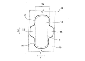
- FIG. 2 is a schematic plan view of the absorbent article strip before being cut by the cutting apparatus shown in FIG. 1.
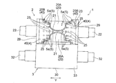
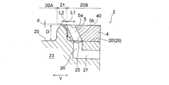
- FIG. 3 is a schematic front view of the first embodiment of the cutting apparatus of the present invention. 4 is a cross-sectional view taken along the line II of FIG.
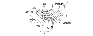
- FIG. 5 is a cross-sectional view of an essential part schematically showing how the absorbent article strip is cut by a cutting device in the manufacturing method shown in FIG. 3.
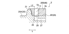
- FIG. 6 is a cross-sectional view (corresponding to FIG. 4) of the main part of the second embodiment of the cutting apparatus of the present invention.
- FIG. 7 is a cross-sectional view (corresponding to FIG.
- FIG. 8 is a cross-sectional view (corresponding to FIG. 4) of an essential part of the fourth embodiment of the cutting apparatus of the present invention.
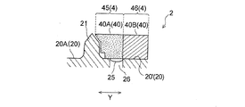
- FIG. 9 is a cross-sectional view (corresponding to FIG. 4) of the main part of the fifth embodiment of the cutting apparatus of the present invention.
- FIG. 10 is a sectional view (corresponding to FIG. 4) of an essential part of the sixth embodiment of the cutting apparatus of the present invention.
- the absorbent article (product) portion is usually configured to include a bulky absorbent body, and thus includes a relatively thick part, whereas the other part. Since the trim part does not include an absorber and is composed of a laminate of one or several thin sheets, the trim part as a whole is a relatively thin thin part. .
- the cutter roll projects from the outer peripheral surface and the outer peripheral surface.
- the present invention relates to a cutting device that can stably separate a trim from a strip.
- the present invention comprises a cutter roll having a cutter blade formed on the outer peripheral surface, and an anvil roll for receiving the cutter blade, and a long strip fed between the two rolls is made into a plurality of short lengths by the cutter blade. It is a cutting device which cuts into a single wafer.
- the outer peripheral surface of the cutter roll is located at a relatively low position, and the sheet body corresponding surface corresponding to the sheet body at the time of cutting the strip-shaped body, and the position relatively high with respect to the sheet body corresponding surface And a trim corresponding surface corresponding to a trim formed of a portion other than the sheet body in the belt-like body.
- the sheet-corresponding surface and the trim-corresponding surface are adjacent to each other with the cutter blade interposed therebetween, and the trim can be sucked and held on the trim-corresponding surface.
- this invention is a manufacturing method of the absorbent article using the said cutting apparatus, Comprising: The absorbent article strip
- the cutting device 1 of the first embodiment is used to cut a long strip 19 into a plurality of short napkins 10 in the manufacture of a sanitary napkin 10 which is a kind of absorbent article.
- the belt-like body 19 is composed of a napkin 10 and a trim 18 including other parts.
- the napkin 10 is arranged at a predetermined interval in the transport direction MD such that the longitudinal direction X thereof coincides with the longitudinal direction of the belt-like body 19 (transport direction MD).
- the napkin 10 has a vertically long absorbent main body 14 that is long in one direction X and a pair of wing portions 15 and 15 that extend from both side edges along the longitudinal direction X of the absorbent main body 14.
- the absorbent main body 14 is a liquid-permeable surface sheet 11 that forms a skin facing surface (a surface facing the wearer's skin when wearing a napkin), a non-skin facing surface [the side opposite to the skin side when wearing a napkin (clothing)
- a liquid-impermeable or water-repellent back sheet 12 that forms a surface directed toward the side
- a liquid-retaining absorbent 13 disposed between the two sheets 11 and 12.
- the wing portion 15 is composed of a laminate of the top sheet 11 and the back sheet 12, and is located at the center in the longitudinal direction X of the absorbent main body 14.
- the top sheet 11 and the back sheet 12 are joined by a known joining process such as hot-melt adhesive, heat sealing, ultrasonic sealing, etc. at the extended portion from the periphery of the absorbent body 13, and thereby the napkin 10.
- a seal portion 16 is formed around the periphery.
- the top sheet 11, the back sheet 12, and the absorbent body 13 various materials conventionally used in absorbent articles such as sanitary napkins can be used without particular limitation.
- the surface sheet 11 for example, a single layer or multilayer nonwoven fabric, a perforated film, or the like can be used.
- the back sheet 12 for example, a liquid-impermeable or water-repellent resin film or a laminate of a resin film and a nonwoven fabric can be used.
- the absorbent body 13 include an aggregate of fibers such as pulp fibers (which may be a non-woven fabric), an absorbent core in which particles of the water-absorbing polymer are held in the aggregate, and the absorbent core is made water-permeable. That are coated with a core wrap sheet made of a conductive thin paper or nonwoven fabric, various known polymer sheets, and the like can be used.
- the trim 18 is formed of a laminate of the top sheet 11 and the back sheet 12, similarly to the wing portion 15. Since the absorbent main body 14 includes the absorbent body 13, the entire absorbent main body 14 is a thick portion having a relatively large thickness, whereas the trim 18 includes the absorbent body. However, since it is composed of a laminate of sheets 11 and 12 smaller than the absorbent body, the trim 18 as a whole is a thin portion having a relatively small thickness. The trim 18 becomes a cut end portion after the napkin 10 is cut from the belt-like body 19 and is usually discarded.
- the cutting device 1 includes a cutter roll 2 having a cutter blade 21 formed on the outer peripheral surface 20, and an anvil roll 3 that receives the cutter blade 21.
- the cutter roll 2 has a rotation shaft 22 that functions as a rotation center line
- the anvil roll 3 has a rotation shaft 32 that functions as a rotation center line
- both the rolls 2 and 3 The outer peripheral surface 20 of the roll 2 and the outer peripheral surface 30 of the roll 3 are arranged so as to be parallel to each other.
- the cutting device 1 is for cutting a long belt-like body 19 in which a plurality of single-wafer bodies 10 (sanitary napkins) are continuously formed into a belt-like shape into individual short-sized sheet bodies 10,
- a cutter roll 2 having a cylindrical metal rotating body 23 supported so as to be rotatable around a rotating shaft 22 and a cylindrical metal rotating body 33 rotating around the rotating shaft 32 in synchronization with the cutter roll 2.
- an anvil roll 3 having a belt-like body 19 passing between the rolls 2 and 3 (rotating bodies 23 and 33) when the rolls 2 and 3 (rotating bodies 23 and 33) are rotating.
- the blades 21 of the cutter roll 2 and the outer peripheral surface 30 of the anvil roll 3 are sandwiched between the blades 21 and cut into individual sheets 10.
- the cutter blade 21 has a shape corresponding to the outer shape (contour when viewed in plan) of a single sheet body 10 (sanitary napkin).
- the single blade body 10 It is continuous without interruption along the outer shape, and has a closed shape in plan view.
- plan view refers to an object on the outer peripheral surface 20 of the cutter roll 2 (the cutter blade 21, a block 4, a suction port 25, a through-hole 5, etc. described later) in the normal direction of the outer peripheral surface 20 ( It means a case where it is viewed from the outside of the cutter roll 2 in the direction orthogonal to the rotation axis 22.
- the cutter blade 21 having a closed shape corresponding to the outer shape of the sheet 10 is formed in the center portion of the cutter roll 2 in the roll width direction Y (direction in which the rotation shaft 22 extends). Two are provided at predetermined intervals in the circumferential direction.
- the outer peripheral surface 20 of the cutter roll 2 corresponds to a trim corresponding to a single-wafer body corresponding surface 20A corresponding to the single-wafer body 10 when the strip-shaped body 19 is cut, and a trim 18 including a portion other than the single-wafer body 10 in the strip-shaped body 19.
- the sheet-corresponding surface 20A and the trim-corresponding surface 20B are adjacent to each other with the cutter blade 21 in between.
- the sheet-corresponding surface 20 ⁇ / b> A is located at the center in the roll width direction Y
- the trim-corresponding surfaces 20 ⁇ / b> B are located on the left and right sides.
- the single wafer corresponding surface 20A is a portion surrounded by the cutter blade 21 on the outer peripheral surface 20, and is provided in the same number as the cutter blades 21 having the closed shape described above. In the first embodiment, two are provided on the outer peripheral surface 20. It has been.
- the area of each single wafer corresponding surface 20A (the area of the portion surrounded by the cutter blade 21 on the outer peripheral surface 20) is substantially the same as the area of the single wafer 10 (sanitary napkin).
- the length (width) of the trim corresponding surface 20B in the roll width direction Y is larger than the length (width) of the trim 18 in the width direction Y (see FIG. 2, the direction orthogonal to the longitudinal direction X).
- the surface 20B is wider than the trim 18.
- the main features of the present invention are as follows: 1) The sheet-corresponding surface 20A is at a relatively low position (compared to the trim-corresponding surface 20B), and the trim-corresponding surface 20B is compared with the sheet-corresponding surface 20A. And 2) a point that the trim 18 can be sucked and held on the trim corresponding surface 20B.
- the trim corresponding surface 20B is formed by raising a part of the cutter roll 2 (outer peripheral surface 20).
- the trim corresponding surface 20 ⁇ / b> B is relatively high (as compared to the single wafer corresponding surface 20 ⁇ / b> A) in the first embodiment.
- the block 4, which is separate from the cutter roll 2, is formed on the outer peripheral surface 20 of the cutter roll 2.
- the sheet-corresponding surface 20A is formed from the outer peripheral surface 20 of the cutter roll 2
- the trim corresponding surface 20B is the outer surface 40 (the outer peripheral surface 20 and the outer surface 20) of the block 4 arranged on the outer peripheral surface 20.
- the height relationship of the outer peripheral surface 20 of the cutter roll 2 is closely related to the magnitude relationship of the diameter of the cutter roll 2, and the single wafer corresponding surface 20 ⁇ / b> A existing at a relatively low position has a relatively large diameter of the cutter roll 2.
- the trim corresponding surface 20 ⁇ / b> B located in a small portion and located in a relatively high position is located in a portion where the diameter of the cutter roll 2 is relatively large.
- the block 4 is made of a non-breathable material such as resin or metal, and corresponds to the trim 18 when the strip 19 is cut on the outer peripheral surface 20 by fixing means (not shown) such as bolts, fittings, and adhesives. Removably fixed to the area.
- the block 4 has a circumferential length of the cutter roll 2 that is obtained by dividing the circumferential length of the cutter roll 2 into two equal parts, and connects the two blocks 4 and 4 to each other on the outer peripheral surface 20. By fixing in this manner, the cutter roll 2 having the structure as shown in FIG. 3 is obtained.
- the block 4 is formed along the cutter blade 21 (arranged in the vicinity of the cutter blade 21 so that the separation distance from the cutter blade 21 is kept constant).
- the block 4 has a cross-sectional view along the roll width direction Y as shown in FIG. 4 (a cross-sectional view in a direction straddling the cutter blade 21). It has an inclined part which inclines along the cutting edge which inclines.
- the sheet-corresponding surface 20 ⁇ / b> A (the outer peripheral surface 20 of the cutter roll 2) and the arrangement region 20 ′ of the block 4 on the outer peripheral surface 20 are flush with each other. Therefore, the level difference D between the single-wafer body-corresponding surface 20A and the trim-corresponding surface 20B matches the thickness of the block 4.
- the sheet body corresponding surface 20A and the arrangement region 20 ′ of the block 4 on the outer peripheral surface 20 are flush with each other.
- the napkin 10 constituting the strip 19 that is the object to be cut is relatively thick and thick, the single-wafer body-corresponding surface 20A has the arrangement region 20 of the block 4 to cope with this.
- the cutter roll 2 is configured so that the depth from the cutting edge of the cutter blade 21 is slightly deeper than ', and as a result, the arrangement region 20' of the block 4 is compared with the sheet-corresponding surface 20A, There may be a case where the height of the step on the outer peripheral surface is relatively high. In that case, the block 4 is fixed on the arrangement region 20 ′ of the block 4 located at a relatively high position, and the single body corresponding surface 20A and the trim corresponding surface 20B (the outer surface 40 of the flock 4) where the block 4 is not arranged. Is a total value of the height (thickness) of the step on the outer peripheral surface and the thickness of the block 4.
- a step D between the sheet-corresponding surface 20A and the trim-corresponding surface 20B (in the first embodiment, the thickness of the block 4) is a protruding height of the cutter blade 21 from the outer peripheral surface 20 (the sheet-corresponding surface 20A). It is set slightly lower than this.
- the step D (thickness of the block 4) means the step (thickness) of the portion having the largest step (thickness) when the step D (thickness of the block 4) is partially different. Therefore, the cutting edge of the cutter blade 21 is located at a position relatively higher than the trim corresponding surface 20B, and between the trim corresponding surface 20B (the outer surface 40 of the block 4) and the cutting edge of the cutter blade 21.
- a relatively small step d is generated, and the cutting edge of the cutter blade 21 is further separated from the outer peripheral surface 20 by the step d than the trim corresponding surface 20B.
- this minute step d substantially equal to the thickness of the trim 18 in the strip 19 cut by the cutter blade 21, the trim 18 is connected to the cutting edge of the cutter blade 21 at and immediately after cutting the strip 19.
- the step d between the trim corresponding surface 20B (the outer surface 40 of the block 4) and the cutting edge of the cutter blade 21 is preferably 0.05 to 2 mm, more preferably 0.5 to 1 mm.
- FIG. 3 and FIG. 4 As shown in FIG. 4, a through-hole 5 (from the outer surface 40 of the block 4 to the inner surface (the surface facing the outer peripheral surface 20 of the cutter roll 2)) that penetrates the block 4 in the thickness direction is formed in the block 4.
- a suction port 25 for sucking and holding the trim 18 to the trim corresponding surface 20B is formed in the arrangement region 20 ′ of the block 4 on the outer peripheral surface 20, and the through hole 5 and the suction port 25 communicate with each other. .
- the suction port 25 has a circular shape in plan view, and a plurality of suction ports 25 are formed in the vicinity of the cutter blade 21 in the arrangement region 20 ′ of the block 4.
- the plurality of suction ports 25 in addition to the vicinity of the cutter blade 21, include two sheet-corresponding surfaces 20 ⁇ / b> A adjacent in the circumferential direction of the cutter roll 2 in the arrangement region 20 ′ of the block 4. It is also formed between 20A, and is formed so as to surround one single body corresponding surface 20A.
- the suction port 25 is an opening on the outer peripheral surface 20 side of the radial hole 26 that extends in the radial direction of the cutter roll 2 from the arrangement region 20 ′ of the block 4 on the outer peripheral surface 20 toward the rotating shaft 22. It is an end.
- the cutter roll 2 extends along the rotation axis 22 from the bottom of each radial hole 26 toward the side surface 29 of the cutter roll 2 (the surface from which the rotation axis 22 protrudes).
- a plurality of axial holes 27 are formed.
- a suction means (not shown) is connected to an opening end (not shown) on the side surface 29 side of the axial hole 27, and by operating the suction means, the inside of the radial hole 26 and the axial direction are arranged.
- the inside of the hole 27 can be maintained at a negative pressure, and at this time, a suction force is generated at the suction port 25.
- the through hole 5 has a constant diameter (diameter of the through hole) throughout the thickness direction of the block 4, and has an opening end 5 a on the outer surface 40 side of the block 4 and an opening end 5 b on the opposite side (inner surface side).
- the same number of through holes 5 as the plurality of suction ports 25 are formed, and the plurality of suction ports 25 and the plurality of through holes 5 (open end portions 5b) correspond one-to-one.
- the diameter of the communicating portion (opening end 5b) with the suction port 25 in the through hole 5 is the same as the diameter of the suction port 25 (opening end on the outer peripheral surface 20 side of the radial hole 26). However, they may be different.
- the through-hole 5 extends obliquely from the suction port 25 toward the cutter blade 21 in a cross-sectional view of the block 4 as shown in FIG. 4 (a cross-sectional view across the cutter blade 21). ing. That is, the opening end portion 5a on the outer surface 40 side of the block 4 in the through hole 5 is closer to the cutter blade 21 than the opening end portion 5b on the opposite side (inner surface side of the block 4) and the suction port 25 opposite thereto. It is close.
- a plurality of suction ports are formed on the outer peripheral surface 30 of the anvil roll 3.
- the suction port formed on the outer peripheral surface 30 is for sucking and holding the strip 19 on the outer peripheral surface 30 when the strip 19 is cut.
- the anvil roll 3 is connected to a suction means (not shown) for generating a suction force at the suction port of the outer peripheral surface 30.
- the belt-like body 19 is supplied between the cutter roll 2 and the anvil roll 3 constituting the cutting device 1, and the belt-like body 19 is formed between the cutter blade 21 and the outer peripheral surface 30 of the anvil roll 3. And a step of cutting by sandwiching them.
- a long strip 19 shown in FIG. 2 is manufactured. More specifically, as shown in FIG. 1, the belt-like topsheet 11 is conveyed toward the cutting device 1, and a plurality of pre-manufactured absorbers 13 are placed on one surface of the topsheet 11. Then, a belt-like back sheet 12 is supplied on the one surface, and is passed between the pair of nip rolls 5, 5 to obtain a belt-like body 19. Sealing means (not shown) is disposed between the pair of nip rolls 5, 5 and the cutting device 1, and the belt-like body 19 that has passed through the pair of nip rolls 5, 5 is introduced into the sealing means.
- the periphery of the portion corresponding to the napkin 10 is heated and pressurized by the sealing means to form the seal portion 16.
- the sealing means to form the seal portion 16.
- it is bonded to one or both predetermined positions of both sheets 11 and 12 by an adhesive application means (not shown). An agent may be applied.
- the belt-like body 19 is supplied between the cutter roll 2 and the anvil roll 3 of the cutting device 1, and between the cutter 21 of the cutter roll 2 and the outer peripheral surface 30 of the anvil roll 3 as shown in FIG. 5. Cut into individual napkins 10 with the pinch.
- the belt-like body 19 includes a thick portion where the portion corresponding to the napkin 10 (short sheet body) is relatively thick, and a thin portion where the portion corresponding to the trim 18 is relatively thin. The thin portion is cut with the cutting edge of the cutter blade 21.
- the belt-like body 19 is in a state in which the top sheet 11 side is sucked and held on the outer peripheral surface 30 of the anvil roll 3, while the napkin 10 faces the single wafer corresponding surface 20A and the trim 18 faces the trim corresponding surface 20B.
- the sheet is cut from the back sheet 12 side by the cutter blade 21 located at the boundary between the single wafer corresponding surface 20A and the trim corresponding surface 20B, and separated into the napkin 10 (product portion) and the strip-shaped trim 18 (cut end portion).
- each cut napkin 10 is transported in the same direction as the transport direction of the band 19 before cutting, as shown in FIG. It may be transferred to the outer peripheral surface 30 by a suction force and transported in a direction different from the transport direction of the strip 19 before cutting.
- the cut strip-shaped trim 18 is sucked and held on the outer surface 40 (trim-corresponding surface) by the suction force of the opening end portion 5a on the outer surface 40 side of the block 4 in the through-hole 5 in the state where it is held by the cutter.
- the trim removing means includes a plurality of rolls for conveying or winding the belt-shaped trim 18, and winds and removes the belt-shaped trim 18 in a roll shape.
- the trim corresponding surface 20 ⁇ / b> B (the outer surface 40 of the block 4) corresponding to the trim 18 having a relatively thin thickness is configured so that the trim 18 can be sucked and held at the time of cutting the strip-shaped body 19 and immediately thereafter.
- the trim corresponding surface 20B is located at a position higher than the single-wafer corresponding surface 20A corresponding to the relatively thick napkin 10 by a level difference D, At the time of cutting 19 and immediately after that, the trim 18 is substantially at the same position with respect to the outer peripheral surface 20 (sheet-fed body-corresponding surface 20A) to the extent that there is a relatively small step d between the cutter blade 21 and the cutting edge.
- the trim 18 can be stably separated from the belt-like body 19, and the sanitary napkin 10 having a predetermined shape can be continuously manufactured efficiently and stably.
- the through-hole 5 is formed in the block 4 and the through-hole 5 and the suction port 25 of the trim corresponding surface 20 ⁇ / b> B communicate with each other, whereby the outer surface 40 of the block 4 in the through-hole 5.
- the opening end 5a on the side functions as a suction port for sucking and holding the trim 18. Therefore, the position of the trim 18 at the time of cutting is more stable, and the trim 18 is less likely to be displaced, so that the cutting accuracy is improved.
- the through-hole 5 is formed in the outer peripheral surface 20 (arrangement region 20 ′ of the block 4) in the cross-sectional view of the block 4 as shown in FIG. 4 (cross-sectional view in the direction straddling the cutter blade 21).
- the opening end portion 5a of the through hole 5 that functions as a suction port for sucking and holding the trim 18 is inclined relative to the suction port 25. It is in a position closer to the blade 21. Since the trim 18 is usually discarded after cutting, it is preferable that the size (area) of the trim 18 is as small as possible.
- the opening end 5a is a cutter blade as compared with the suction port 25. Therefore, the width of the trim 18 (the length in the roll width direction Y) can be made as narrow as possible, and the size of the trim 18 can be reduced to reduce the waste portion. it can.
- each part of the cutting device 1 are preferably set as follows.
- the step D (see FIG. 4) between the trim corresponding surface 20B (the outer surface 40 of the convex portion 4) and the single wafer corresponding surface 20A is preferably 0.01 to 20 mm, more preferably 0.5 to 10 mm. .
- the protruding height of the cutter blade 21 from the outer peripheral surface 20 (the sheet-corresponding surface 20A) is preferably 2 to 20 mm, more preferably 5 to 10 mm.
- the width of the cutter blade 21 (corresponding to the length in the roll width direction Y in FIG. 4) is preferably 2 to 10 mm, more preferably 3 to 8 mm.
- the diameter L1 see FIG.
- the distance L2 (see FIG. 4) between the opening end 5a on the outer surface 40 side of the block 4 and the cutter blade 21 (blade edge) in the through hole 5 is preferably 1 to 10 mm, more preferably 2 to 5 mm.
- FIG. 6 shows the main parts (cutter blade and block) of the second embodiment of the cutting apparatus of the present invention.
- the through hole 5 is in the normal direction of the outer peripheral surface 20 from the suction port 25 formed in the outer peripheral surface 20 (arrangement region 20 ′ of the block 4) (the protruding direction from the outer peripheral surface 20 of the cutter blade 21). ) Is different from the first embodiment in which the through hole 5 extends obliquely from the suction port 25 toward the cutter blade 21.
- the second embodiment substantially the same effect as that of the first embodiment can be obtained.
- FIG. 7 shows the main parts (cutter blade and block) of the third embodiment of the cutting apparatus of the present invention.
- a plurality of (three in FIG. 7) through holes 5 communicate with one suction port 25, and each of the plurality of through holes 5 has one suction port 25.
- the caliber is small compared to.
- Each of the plurality of through holes 5 in the third embodiment has a constant diameter over the entire area of the block 4 in the thickness direction.
- the plurality of through holes 5 each extend obliquely from the suction port 25 toward the cutter blade 21.
- the suction port 25 is subdivided without changing the design, and the trim is sucked and held by using a larger number of through holes 5 (opening end portions 5a) than the suction port 25. Therefore, it becomes difficult to be influenced by the surface state of the sheet that is the object to be cut, and the adhesion between the sheet and the trim corresponding surface 20B (the outer surface 40 of the block 4) is improved, so that the suction and holding of the trim can be further stabilized. .
- the outer peripheral surface of the cutter roll is usually made of a hard metal, it is technically and costly to make a small hole (trim suction port) having an opening end portion having a small diameter on the outer peripheral surface.
- the through-hole 5 having such a small hole can be easily formed by forming the block 4 from a material that is relatively easy to process such as resin.
- the ratio (the latter / the former) of the diameter of the through hole 5 (diameter of the through hole) to the diameter of the suction port 25 (the diameter of the suction port) is preferably 0.01 to 0.5, more preferably 0.04 to 0. .4.
- FIG. 8 shows the main parts (cutter blade and block) of the fourth embodiment of the cutting apparatus of the present invention.
- the opening end portion 5a on the outer surface 40 side of the block 4 in the through hole 5 is an opening on the inner surface side of the block 4 (on the side facing the outer peripheral surface 20 (arrangement region 20 ′ of the block 4)).
- the diameter is smaller than that of the end portion 5b and the suction port 25.
- the diameter of the through hole 5 in the fourth embodiment gradually decreases from the inner surface side to the outer surface 40 side of the block 4, and the opening end 5 b has the same shape (circular shape) as the suction port 25. And have the same dimensions (same diameter).
- the through hole 5 extends obliquely from the suction port 25 toward the cutter blade 21 in a sectional view of the convex portion 4 (a sectional view in a direction straddling the cutter blade 21).
- the same effects as in the first embodiment are achieved.
- the diameter of the opening end portion 5a of the through hole 5 is smaller than that of the opening end portion 5b located on the opposite side and the suction port 25 facing the opening end portion 5b.
- the trim width can be made smaller than that of the first embodiment, and further reduction of the waste portion can be expected.
- the opening end portion 5a that directly acts on the suction of the trim has a relatively smaller suction area than the opening end portion 5b, so that the suction areas of both the opening end portions 5a and 5b are equal.
- the flow rate of the air flow (vacuum air) generated by suction is increased, and the effect of improving the trim suction force can be expected.
- FIG. 9 shows the main parts (cutter blade and block) of the fifth embodiment of the cutting apparatus of the present invention.
- a portion 45 (from the suction port 25 at the position farthest away from the cutter blade 21 when the plurality of suction ports 25 are formed) to the cutter blade 21 ( A portion closer to the cutter blade 21 than that including the portion corresponding to the suction port 25.
- an inner portion 45 is formed from a porous material.
- the porous material has innumerable pores on the outer surface and inside, and therefore, the entire porous material has air permeability. Therefore, the inner portion 45 made of the porous material has air permeability.
- the suction force when a suction force is generated in the suction port 25, the suction force extends into the inner portion 45, and as a result, the inner portion 45.
- a suction force is generated over the entire outer surface 40A (a part of the outer surface 40 of the block 4).
- the porous material for example, hard urethane, sponge, porous metal, or the like can be used.
- the porous metal for example, those manufactured by Taisei Kogyo Co., Ltd. can be used.
- the portion 46 (hereinafter also referred to as the outer portion 46) other than the inner portion 45 in the block 4 that is disposed adjacent to the inner portion 45 is from the viewpoint of preventing a reduction in suction force generated in the inner portion 45.
- FIG. 10 shows the main parts (cutter blades and blocks) of the sixth embodiment of the cutting apparatus of the present invention.
- a gap 6 is provided between the cutter blade 21 and the block 4, and the gap 6 and the suction port 25 communicate with each other.
- the gap 6 is continuously provided along the cutter blade 21 over the entire circumference of the cutter blade 21.
- a gap is provided between the cutter blade 21 and the block 4.
- a feature of the sixth embodiment is that the gap 6 and the suction port 25 communicate with each other. .
- the space portion 7 is formed between the inner surface 41A (the surface facing the outer peripheral surface 20) of the inner portion 45 of the block 4 and the outer peripheral surface 20 (arrangement region 20 ′ of the block 4).
- the space portion 7 communicates with the gap 6.
- the outer portion 46 of the block 4 adjacent to the inner portion 45 is in close contact with the outer peripheral surface 20 (arrangement region 20 ′ of the block 4), and a substantial space is formed between the outer portion 46 and the outer peripheral surface 20. The part is not formed.
- a suction force is generated at the suction port 25, the suction force reaches the space 7 and the gap 6 communicating with the space 7. As a result, a suction force is generated in the gap 6.
- the trim can be sucked and held on the trim corresponding surface 20B (the outer surface 40 of the block 4) by the suction force of the gap 6, the block 4 (the inner portion 45 and the outer portion 46) A through hole communicating with the suction port 25 of the outer peripheral surface 20 is not formed, and the outer surface 40 (the outer surface 40A of the inner portion 45 and the outer surface 40B of the outer portion) itself does not have a trim suction holding function.
- the trim since the trim is stably sucked and held by the trim corresponding surface 20B (the outer surface 40 of the block 4) by the suction force of the gap 6, the trim from the belt-like body is performed as in the first embodiment. Can be stably performed.
- the shape of the cutter blade 21 in plan view can be an arbitrary shape that matches the shape (cut shape) of the absorbent article.
- the shape of the block 4 in a plan view, the number of the suction ports 25, and the arrangement location can be changed as appropriate.
- Absorbent articles produced in the present invention are not limited to sanitary napkins, but broadly include articles used to absorb liquids discharged from the human body. In addition to sanitary napkins, disposable diapers, incontinence pads, panty liners, etc. Are also included.
- the wing part 15 in the napkin 10 was formed from the laminated body of the surface sheet 11 and the back surface sheet 12, it may be formed from the sheet
- the sheet material for forming the wing portion is sandwiched and fixed between the top sheet 11 and the back sheet 12 on both the left and right sides in the longitudinal direction of the absorbent main body 14 or bonded to the skin facing surface of the top sheet 11. Or joined to the non-skin facing surface of the back sheet 12.
- the napkin 10 does not need to have the wing part 15, and this invention is applicable also to manufacture of the sanitary napkin (planar view sanitary napkin in plan view) which does not have a wing part.
- the block 4 is formed along the cutter blade 21, but may not be formed along the cutter blade 21.
- the two blade corresponding surfaces 20 ⁇ / b> A and 20 ⁇ / b> A adjacent to each other in the circumferential direction of the cutter roll 2 may be separated by the cutter blade 21.
- the suction port 25 for sucking and holding the trim 18 to the trim corresponding surface 20B has a circular shape in plan view as shown in FIG.
- the shape is not limited to this and can be appropriately changed.
- the shape may have a groove shape extending in the circumferential direction of the cutter roll 2.
- the groove-like suction port 25 is a groove portion in which a part of the arrangement region 20 ′ of the block 4 on the outer peripheral surface 20 of the cutter roll 2 is recessed in a concave shape, and suction means (not shown) is provided at a predetermined position of the groove portion.
- the axial direction hole 27 connected to can be communicated.
- each of the plurality of through holes 5 has an opening end 5 a on the outer surface 40 side of the block 4 compared to the opening end 5 b on the inner surface side of the block 4.
- the diameter may gradually decrease from the inner surface side of the block 4 toward the outer surface 40 side as in the through hole 5 in the fourth embodiment shown in FIG.
- the through hole 5 extends obliquely from the suction port 25 toward the cutter blade 21, but the second embodiment shown in FIG.
- the through holes 5 of various forms described above are communicated with the suction port 25 of the outer peripheral surface 20 in the portion (inner portion 45) made of the porous material in the block 4. You may form in. Further, in the sixth embodiment shown in FIG. 10, the through holes 5 of the various forms described above are formed in the block 4 (inner part 45, outer part 46) so as to communicate with the suction port 25 of the outer peripheral surface 20. May be.
- a cutter roll having a cutter blade formed on the outer peripheral surface and an anvil roll that receives the cutter blade, and a long belt-like body supplied between both rolls,
- a cutting device for cutting into single wafers The outer peripheral surface of the cutter roll is located at a relatively low position, and the sheet body corresponding surface corresponding to the sheet body at the time of cutting the strip-shaped body, and the position relatively high with respect to the sheet body corresponding surface
- a trim corresponding surface corresponding to a trim composed of a portion other than the sheet body in the strip, and the sheet corresponding surface and the trim corresponding surface are adjacent to each other with the cutter blade interposed therebetween.
- a cutting device configured to suck and hold the trim on the trim-corresponding surface.
- ⁇ 2> The cutting device according to ⁇ 1>, wherein a relatively high position of the trim corresponding surface is formed by disposing a block separate from the cutter roll on an outer peripheral surface of the cutter roll.
- the block includes an inclined portion that is formed along the cutter blade and is inclined along a blade edge that the cutter blade is inclined.
- ⁇ 4> In the block, a through-hole penetrating the block in the thickness direction is formed, and the trim is sucked and held on the trim-corresponding surface in the arrangement area of the block on the outer peripheral surface of the cutter roll.
- ⁇ 5> The cutting device according to ⁇ 4>, wherein the through hole extends obliquely from the suction port toward the cutter blade in a cross-sectional view of the block.
- a plurality of the through holes communicate with one suction port, and each of the plurality of through holes has a smaller diameter than one suction port ⁇ 4> or ⁇ 5>
- the opening end portion on the outer surface side of the block in the through hole is any one of ⁇ 4> to ⁇ 6>, which has a smaller diameter than the opening end portion on the inner surface side of the block and the suction port.
- ⁇ 8> The cutting device according to any one of ⁇ 2> to ⁇ 7>, wherein a portion of the block from the suction port to the cutter blade is formed of a porous material.
- ⁇ 9> The cutting device according to any one of ⁇ 2> to ⁇ 8>, wherein a gap is provided between the cutter blade and the block, and the gap and the suction port communicate with each other.
- ⁇ 10> The cutting device according to any one of ⁇ 1> to ⁇ 9>, wherein a cutting edge of the cutter blade is located at a position relatively higher than the trim corresponding surface.
- ⁇ 11> The cutting height according to any one of ⁇ 1> to ⁇ 10>, wherein a protruding height of the cutter blade from the outer peripheral surface of the cutter roll is 2 mm or more and 20 mm or less and 5 mm or more and 10 mm or less. apparatus.
- the trimming device according to any one of ⁇ 1> to ⁇ 11>, wherein the trim includes a laminate of a top sheet and a back sheet.
- the cutter roll has a rotation axis that functions as a rotation center line
- the anvil roll has a rotation axis that functions as a rotation center line
- both the rolls have their rotation axes parallel to each other and the cutter roll.
- the cutting apparatus according to any one of ⁇ 1> to ⁇ 12>, wherein the outer peripheral surface of the anvil roll and the outer peripheral surface of the anvil roll are arranged to face each other.
- the cutter blade has a shape corresponding to the outer shape (contour when viewed in plan) of a single sheet body, and is continuous without being interrupted along the outer shape of the single sheet body.
- the cutting device according to any one of ⁇ 1> to ⁇ 13>, which has a closed shape in plan view.
- a cutter blade having a closed shape corresponding to the outer shape of the sheet body has a predetermined interval in the circumferential direction of the cutter roll at a central portion in the roll width direction Y (direction in which the rotation axis extends) of the cutter roll.
- the cutting apparatus according to ⁇ 14>, wherein a plurality of the cutting apparatuses are provided.
- ⁇ 16> The length (width) of the trim corresponding surface in the roll width direction Y is larger than the length (width) of the trim in the width direction Y, and the trim corresponding surface is wider than the trim.
- the cutting apparatus according to any one of ⁇ 1> to ⁇ 15>.
- ⁇ 17> The cutting device according to any one of ⁇ 1> to ⁇ 16>, wherein the sheet-corresponding surface is located at a relatively lower position than the trim-corresponding surface.
- ⁇ 18> The cutting device according to any one of ⁇ 2> to ⁇ 17>, wherein a step between the single wafer corresponding surface and the trim corresponding surface matches a thickness of the block.
- ⁇ 19> Any one of ⁇ 1> to ⁇ 18>, wherein a step between the trim corresponding surface and the single wafer corresponding surface is 0.01 mm or more and 20 mm or less and 0.5 mm or more and 10 mm or less.
- the cutting edge of the cutter blade is located relatively higher than the trim corresponding surface, and a step is generated between the trim corresponding surface and the cutting edge of the cutter blade.
- the cutting apparatus according to any one of ⁇ 1> to ⁇ 19>, wherein the step is set to be substantially equal to the thickness of the trim in the belt-shaped body cut by the cutter blade.
- the suction port has a circular shape in plan view and is formed in the vicinity of a cutter blade in a block arrangement region. .
- the plurality of suction ports are also formed between the plurality of sheet-corresponding surfaces adjacent in the circumferential direction of the cutter roll in the block arrangement region.
- the through-hole has a constant diameter (diameter of the through-hole) over the entire area in the thickness direction of the block, and the opening end on the outer surface side of the block and the opening end on the opposite side (inner surface side) are:
- Each has the same shape and the same size (same diameter) as the suction port, and the number of through holes is the same as the number of suction ports, and a plurality of suction ports and a plurality of through holes (opening end portions) Is a cutting apparatus according to any one of ⁇ 4> to ⁇ 22>, which corresponds one-to-one.
- ⁇ 24> The cutting device according to any one of ⁇ 4> to ⁇ 23>, wherein a diameter of the through hole of the block is 1 mm or more and 10 mm or less and 2 mm or more and 5 mm or less. ⁇ 25> The distance between the opening end on the outer surface side of the block in the through hole and the cutter blade (blade edge) is 1 mm or more and 10 mm or less, and 2 mm or more and 5 mm or less ⁇ 4> to ⁇ 24> The cutting device according to any one of the above.
- a plurality of suction ports are formed on the outer peripheral surface of the anvil roll for sucking and holding the band-like member on the outer peripheral surface when the strip-like member is cut.
- a method for producing an absorbent article using the cutting device according to any one of ⁇ 1> to ⁇ 26> An absorbent article strip formed by continuously forming a plurality of absorbent articles in a strip shape is supplied between the cutter roll and the anvil roll, and the absorbent article strip is provided on the outer periphery of the cutter blade and the anvil roll.
- the manufacturing method of an absorbent article which comprises the process of pinching and cutting between surfaces.
- a portion corresponding to the sheet body is a thick portion having a relatively large thickness
- a portion corresponding to the trim is a thin portion having a relatively small thickness
- ⁇ 31> In the state where the top sheet side is sucked and held on the outer peripheral surface of the anvil roll, the absorbent article is opposed to the single wafer corresponding surface, and the trim is opposed to the trim corresponding surface.
- ⁇ 27> to ⁇ 30 which are cut from the back sheet side by the cutter blade located at the boundary between the sheet-corresponding surface and the trim-corresponding surface and separated into the absorbent article and the strip-shaped trim.
- ⁇ 32> The cut strip-shaped trim is conveyed to the trim removing means disposed above the cutter roll by the rotation of the cutter roll while being sucked and held on the trim corresponding surface.
- the trim removing means includes a plurality of rolls for transporting or winding the belt-like trim, and takes up and removes the belt-like trim in a roll. Any one of ⁇ 27> to ⁇ 32> A method for producing an absorbent article according to claim 1. ⁇ 34> The method for producing an absorbent article according to any one of ⁇ 27> to ⁇ 33>, wherein the absorbent article is a sanitary napkin, a disposable diaper, an incontinence pad, or a panty liner.
- the trim can be stably separated from the strip.
- an absorbent article of a predetermined shape can be manufactured efficiently and continuously by stably separating the trim from the strip.
Landscapes
- Life Sciences & Earth Sciences (AREA)
- Forests & Forestry (AREA)
- Engineering & Computer Science (AREA)
- Mechanical Engineering (AREA)
- Absorbent Articles And Supports Therefor (AREA)
- Perforating, Stamping-Out Or Severing By Means Other Than Cutting (AREA)
Abstract
La présente invention concerne un dispositif de coupe équipé d'un cylindre de coupe (2) sur la surface circonférentielle externe (20) sur laquelle est formée une lame de coupe (21), et un cylindre de contre-partie (3) qui reçoit la lame de coupe (21). La surface circonférentielle externe (20) du cylindre de coupe (2) comprend une surface de support de feuille (20A) qui est située à une position relativement inférieure et qui supporte la feuille quand un corps ayant la forme d'une bande est en train d'être coupé, et une surface de support de parties coupées (20B) qui est située à une position élevée par rapport à la surface de support de feuille (20A) et qui supporte les parties coupées provenant des portions non-feuilles du corps ayant la forme d'une bande. La surface de support de feuille (20A) est adjacente à la surface de support de parties coupées (20B), la lame de coupe (21) étant disposée entre celles-ci. Le dispositif est conçu de façon à être capable de tirer et maintenir les parties coupées sur la surface de support de parties coupées (20B).
Priority Applications (1)
| Application Number | Priority Date | Filing Date | Title |
|---|---|---|---|
| CN201280058500.XA CN103957853B (zh) | 2011-12-14 | 2012-12-06 | 截断装置 |
Applications Claiming Priority (2)
| Application Number | Priority Date | Filing Date | Title |
|---|---|---|---|
| JP2011-273010 | 2011-12-14 | ||
| JP2011273010A JP5913951B2 (ja) | 2011-12-14 | 2011-12-14 | 裁断装置 |
Publications (1)
| Publication Number | Publication Date |
|---|---|
| WO2013089009A1 true WO2013089009A1 (fr) | 2013-06-20 |
Family
ID=48612462
Family Applications (1)
| Application Number | Title | Priority Date | Filing Date |
|---|---|---|---|
| PCT/JP2012/081598 Ceased WO2013089009A1 (fr) | 2011-12-14 | 2012-12-06 | Dispositif de coupe |
Country Status (3)
| Country | Link |
|---|---|
| JP (1) | JP5913951B2 (fr) |
| CN (1) | CN103957853B (fr) |
| WO (1) | WO2013089009A1 (fr) |
Cited By (3)
| Publication number | Priority date | Publication date | Assignee | Title |
|---|---|---|---|---|
| WO2015033242A2 (fr) | 2013-09-06 | 2015-03-12 | Kimberly-Clark Worldwide, Inc. | Plaque pour un contre-cylindre avec une zone de vide réduit pour une utilisation dans un système de glissement-découpe et procédé d'utilisation correspondant |
| WO2021206591A1 (fr) * | 2020-04-06 | 2021-10-14 | Essity Hygiene And Health Aktiebolag | Procédé de transfert d'un ou plusieurs éléments de matériau de non-tissé découpés pour une utilisation dans un article absorbant |
| CN113524319A (zh) * | 2021-06-15 | 2021-10-22 | 苏州永硕电子有限公司 | 一种圆刀机调节装置 |
Families Citing this family (9)
| Publication number | Priority date | Publication date | Assignee | Title |
|---|---|---|---|---|
| JP5868459B2 (ja) * | 2014-06-30 | 2016-02-24 | ユニ・チャーム株式会社 | 切断装置 |
| JP6520443B2 (ja) * | 2014-07-15 | 2019-05-29 | 東洋製罐株式会社 | 外形カット装置 |
| CN105943246B (zh) * | 2016-04-23 | 2019-08-30 | 泉州智造者机械设备有限公司 | 数控成人纸尿裤生产线的吸收材料滚切设备 |
| DE102017208261A1 (de) * | 2016-06-21 | 2017-12-21 | Heidelberger Druckmaschinen Ag | Stanzzylinder zum Stanzen von Bedruckstoff |
| CN106361500B (zh) * | 2016-08-26 | 2019-05-03 | 松嘉(泉州)机械有限公司 | 一种纸尿裤大耳片短切纵向变距方法及其系统 |
| CN106272695B (zh) * | 2016-08-26 | 2018-04-10 | 松嘉(泉州)机械有限公司 | 一种纸尿裤耳片短切装置 |
| JP6855803B2 (ja) * | 2017-01-17 | 2021-04-07 | 三菱マテリアル株式会社 | ロータリーダイカッターのダイカットロール |
| WO2019106731A1 (fr) * | 2017-11-28 | 2019-06-06 | 花王株式会社 | Procédé de production d'un absorbeur et procédé de production d'article absorbant |
| CN112847992B (zh) * | 2020-12-31 | 2022-08-26 | 江苏汇锦然医疗器械有限公司 | 一种反复黏贴型医用泡沫敷料及制备装置 |
Citations (3)
| Publication number | Priority date | Publication date | Assignee | Title |
|---|---|---|---|---|
| WO2002070213A1 (fr) * | 2001-03-02 | 2002-09-12 | Zuiko Corporation | Dispositif et procede servant a couper et a evacuer une bande |
| JP2006015485A (ja) * | 2004-07-02 | 2006-01-19 | Sandvik Intellectual Property Hb | ロータリーカッタードラムおよびこれを備えたロータリーカッターユニット |
| JP2008237796A (ja) * | 2007-03-29 | 2008-10-09 | Daio Paper Corp | 吸収性物品の製品カッター装置 |
-
2011
- 2011-12-14 JP JP2011273010A patent/JP5913951B2/ja active Active
-
2012
- 2012-12-06 CN CN201280058500.XA patent/CN103957853B/zh active Active
- 2012-12-06 WO PCT/JP2012/081598 patent/WO2013089009A1/fr not_active Ceased
Patent Citations (3)
| Publication number | Priority date | Publication date | Assignee | Title |
|---|---|---|---|---|
| WO2002070213A1 (fr) * | 2001-03-02 | 2002-09-12 | Zuiko Corporation | Dispositif et procede servant a couper et a evacuer une bande |
| JP2006015485A (ja) * | 2004-07-02 | 2006-01-19 | Sandvik Intellectual Property Hb | ロータリーカッタードラムおよびこれを備えたロータリーカッターユニット |
| JP2008237796A (ja) * | 2007-03-29 | 2008-10-09 | Daio Paper Corp | 吸収性物品の製品カッター装置 |
Cited By (8)
| Publication number | Priority date | Publication date | Assignee | Title |
|---|---|---|---|---|
| WO2015033242A2 (fr) | 2013-09-06 | 2015-03-12 | Kimberly-Clark Worldwide, Inc. | Plaque pour un contre-cylindre avec une zone de vide réduit pour une utilisation dans un système de glissement-découpe et procédé d'utilisation correspondant |
| EP3041772A4 (fr) * | 2013-09-06 | 2017-12-27 | Kimberly-Clark Worldwide, Inc. | Plaque pour un contre-cylindre avec une zone de vide réduit pour une utilisation dans un système de glissement-découpe et procédé d'utilisation correspondant |
| US10308462B2 (en) | 2013-09-06 | 2019-06-04 | Kimberly-Clark Worldwide, Inc. | Plate for an anvil roll with a reduced-vacuum region for use in a slip and cut system and method of using the same |
| EP3822205A1 (fr) * | 2013-09-06 | 2021-05-19 | Kimberly-Clark Worldwide, Inc. | Plaque pour un contre-cylindre avec une zone de vide réduit pour une utilisation dans un système de glissement-découpe |
| WO2021206591A1 (fr) * | 2020-04-06 | 2021-10-14 | Essity Hygiene And Health Aktiebolag | Procédé de transfert d'un ou plusieurs éléments de matériau de non-tissé découpés pour une utilisation dans un article absorbant |
| CN115151228A (zh) * | 2020-04-06 | 2022-10-04 | 易希提卫生与保健公司 | 传送一个或更多切出的非织造材料构件以用于吸收性物品的方法 |
| US11857399B2 (en) | 2020-04-06 | 2024-01-02 | Essity Hygiene And Health Aktiebolag | Method for transferring one or more cut-out nonwoven material members for use in an absorbent article |
| CN113524319A (zh) * | 2021-06-15 | 2021-10-22 | 苏州永硕电子有限公司 | 一种圆刀机调节装置 |
Also Published As
| Publication number | Publication date |
|---|---|
| JP5913951B2 (ja) | 2016-05-11 |
| JP2013123504A (ja) | 2013-06-24 |
| CN103957853A (zh) | 2014-07-30 |
| CN103957853B (zh) | 2015-11-25 |
Similar Documents
| Publication | Publication Date | Title |
|---|---|---|
| JP5913951B2 (ja) | 裁断装置 | |
| CN111405886B (zh) | 吸收性物品的包装体和吸收性物品的包装体的制造方法 | |
| TW201125543A (en) | Method and device for manufacturing composite of continuous sheets for absorptive article | |
| US20140338822A1 (en) | Method of manufacturing absorbent article | |
| CN106029025B (zh) | 吸收体的制造方法 | |
| JP5996448B2 (ja) | 吸収性物品の製造装置及び吸収性物品の製造方法 | |
| WO2019107333A1 (fr) | Procédé de production de morceaux de feuille, appareil de production de production de morceaux de feuille et procédé de production de corps absorbant | |
| CN111093576A (zh) | 吸收体的制造方法和吸收体的制造装置 | |
| EP3466381B1 (fr) | Procédé de production d'article absorbant | |
| CA2955743A1 (fr) | Operation de decoupe par glissement a l'aide d'une force de retenue electrique statique et appareil de liaison par ultrasons | |
| CA2967387A1 (fr) | Unite de traitement de bande resistante a la contamination par adhesif | |
| JP6591136B2 (ja) | 吸収体及び吸収性物品の製造方法並びに吸収体及び吸収性物品の製造装置 | |
| JP6108598B2 (ja) | 被加圧物の加圧装置及び加圧方法、被加工物の接合方法並びに吸収性物品の製造方法 | |
| WO2015093303A1 (fr) | Procédé de fabrication de corps absorbant | |
| CN107613922B (zh) | 吸收制品以及用于制造吸收制品的方法和装置 | |
| JP2016067734A (ja) | 吸収性物品を製造する方法 | |
| JP6220795B2 (ja) | 吸収性物品に係る連続シートの複合体の製造方法、及び製造装置 | |
| CN110603015B (zh) | 吸收体的制造方法和吸收性物品的制造方法 | |
| JP6410402B2 (ja) | 使い捨て着用物品の製造方法 | |
| CN108348360B (zh) | 吸收性物品的制造方法和吸收性物品的制造装置 | |
| JP6356980B2 (ja) | 吸収体の製造方法及び製造装置 | |
| TW201109000A (en) | Method for manufacturing wearing article | |
| JP2008136642A (ja) | 縦長物品の製造方法 |
Legal Events
| Date | Code | Title | Description |
|---|---|---|---|
| 121 | Ep: the epo has been informed by wipo that ep was designated in this application |
Ref document number: 12856631 Country of ref document: EP Kind code of ref document: A1 |
|
| NENP | Non-entry into the national phase |
Ref country code: DE |
|
| 122 | Ep: pct application non-entry in european phase |
Ref document number: 12856631 Country of ref document: EP Kind code of ref document: A1 |