WO2013094367A1 - Matériel d'usinage - Google Patents
Matériel d'usinage Download PDFInfo
- Publication number
- WO2013094367A1 WO2013094367A1 PCT/JP2012/080429 JP2012080429W WO2013094367A1 WO 2013094367 A1 WO2013094367 A1 WO 2013094367A1 JP 2012080429 W JP2012080429 W JP 2012080429W WO 2013094367 A1 WO2013094367 A1 WO 2013094367A1
- Authority
- WO
- WIPO (PCT)
- Prior art keywords
- cover
- support member
- bed
- processing
- machine tool
- Prior art date
- Legal status (The legal status is an assumption and is not a legal conclusion. Google has not performed a legal analysis and makes no representation as to the accuracy of the status listed.)
- Ceased
Links
Images




Classifications
-
- B—PERFORMING OPERATIONS; TRANSPORTING
- B23—MACHINE TOOLS; METAL-WORKING NOT OTHERWISE PROVIDED FOR
- B23Q—DETAILS, COMPONENTS, OR ACCESSORIES FOR MACHINE TOOLS, e.g. ARRANGEMENTS FOR COPYING OR CONTROLLING; MACHINE TOOLS IN GENERAL CHARACTERISED BY THE CONSTRUCTION OF PARTICULAR DETAILS OR COMPONENTS; COMBINATIONS OR ASSOCIATIONS OF METAL-WORKING MACHINES, NOT DIRECTED TO A PARTICULAR RESULT
- B23Q3/00—Devices holding, supporting, or positioning work or tools, of a kind normally removable from the machine
- B23Q3/02—Devices holding, supporting, or positioning work or tools, of a kind normally removable from the machine for mounting on a work-table, tool-slide, or analogous part
- B23Q3/10—Auxiliary devices, e.g. bolsters, extension members
-
- B—PERFORMING OPERATIONS; TRANSPORTING
- B23—MACHINE TOOLS; METAL-WORKING NOT OTHERWISE PROVIDED FOR
- B23Q—DETAILS, COMPONENTS, OR ACCESSORIES FOR MACHINE TOOLS, e.g. ARRANGEMENTS FOR COPYING OR CONTROLLING; MACHINE TOOLS IN GENERAL CHARACTERISED BY THE CONSTRUCTION OF PARTICULAR DETAILS OR COMPONENTS; COMBINATIONS OR ASSOCIATIONS OF METAL-WORKING MACHINES, NOT DIRECTED TO A PARTICULAR RESULT
- B23Q11/00—Accessories fitted to machine tools for keeping tools or parts of the machine in good working condition or for cooling work; Safety devices specially combined with or arranged in, or specially adapted for use in connection with, machine tools
- B23Q11/08—Protective coverings for parts of machine tools; Splash guards
-
- B—PERFORMING OPERATIONS; TRANSPORTING
- B23—MACHINE TOOLS; METAL-WORKING NOT OTHERWISE PROVIDED FOR
- B23Q—DETAILS, COMPONENTS, OR ACCESSORIES FOR MACHINE TOOLS, e.g. ARRANGEMENTS FOR COPYING OR CONTROLLING; MACHINE TOOLS IN GENERAL CHARACTERISED BY THE CONSTRUCTION OF PARTICULAR DETAILS OR COMPONENTS; COMBINATIONS OR ASSOCIATIONS OF METAL-WORKING MACHINES, NOT DIRECTED TO A PARTICULAR RESULT
- B23Q7/00—Arrangements for handling work specially combined with or arranged in, or specially adapted for use in connection with, machine tools, e.g. for conveying, loading, positioning, discharging, sorting
- B23Q7/04—Arrangements for handling work specially combined with or arranged in, or specially adapted for use in connection with, machine tools, e.g. for conveying, loading, positioning, discharging, sorting by means of grippers
-
- B—PERFORMING OPERATIONS; TRANSPORTING
- B23—MACHINE TOOLS; METAL-WORKING NOT OTHERWISE PROVIDED FOR
- B23Q—DETAILS, COMPONENTS, OR ACCESSORIES FOR MACHINE TOOLS, e.g. ARRANGEMENTS FOR COPYING OR CONTROLLING; MACHINE TOOLS IN GENERAL CHARACTERISED BY THE CONSTRUCTION OF PARTICULAR DETAILS OR COMPONENTS; COMBINATIONS OR ASSOCIATIONS OF METAL-WORKING MACHINES, NOT DIRECTED TO A PARTICULAR RESULT
- B23Q1/00—Members which are comprised in the general build-up of a form of machine, particularly relatively large fixed members
- B23Q1/01—Frames, beds, pillars or like members; Arrangement of ways
- B23Q1/017—Arrangements of ways
-
- B—PERFORMING OPERATIONS; TRANSPORTING
- B23—MACHINE TOOLS; METAL-WORKING NOT OTHERWISE PROVIDED FOR
- B23Q—DETAILS, COMPONENTS, OR ACCESSORIES FOR MACHINE TOOLS, e.g. ARRANGEMENTS FOR COPYING OR CONTROLLING; MACHINE TOOLS IN GENERAL CHARACTERISED BY THE CONSTRUCTION OF PARTICULAR DETAILS OR COMPONENTS; COMBINATIONS OR ASSOCIATIONS OF METAL-WORKING MACHINES, NOT DIRECTED TO A PARTICULAR RESULT
- B23Q1/00—Members which are comprised in the general build-up of a form of machine, particularly relatively large fixed members
- B23Q1/03—Stationary work or tool supports
-
- B—PERFORMING OPERATIONS; TRANSPORTING
- B23—MACHINE TOOLS; METAL-WORKING NOT OTHERWISE PROVIDED FOR
- B23Q—DETAILS, COMPONENTS, OR ACCESSORIES FOR MACHINE TOOLS, e.g. ARRANGEMENTS FOR COPYING OR CONTROLLING; MACHINE TOOLS IN GENERAL CHARACTERISED BY THE CONSTRUCTION OF PARTICULAR DETAILS OR COMPONENTS; COMBINATIONS OR ASSOCIATIONS OF METAL-WORKING MACHINES, NOT DIRECTED TO A PARTICULAR RESULT
- B23Q11/00—Accessories fitted to machine tools for keeping tools or parts of the machine in good working condition or for cooling work; Safety devices specially combined with or arranged in, or specially adapted for use in connection with, machine tools
- B23Q11/08—Protective coverings for parts of machine tools; Splash guards
- B23Q11/0891—Protective coverings for parts of machine tools; Splash guards arranged between the working area and the operator
-
- B—PERFORMING OPERATIONS; TRANSPORTING
- B23—MACHINE TOOLS; METAL-WORKING NOT OTHERWISE PROVIDED FOR
- B23Q—DETAILS, COMPONENTS, OR ACCESSORIES FOR MACHINE TOOLS, e.g. ARRANGEMENTS FOR COPYING OR CONTROLLING; MACHINE TOOLS IN GENERAL CHARACTERISED BY THE CONSTRUCTION OF PARTICULAR DETAILS OR COMPONENTS; COMBINATIONS OR ASSOCIATIONS OF METAL-WORKING MACHINES, NOT DIRECTED TO A PARTICULAR RESULT
- B23Q39/00—Metal-working machines incorporating a plurality of sub-assemblies, each capable of performing a metal-working operation
- B23Q39/02—Metal-working machines incorporating a plurality of sub-assemblies, each capable of performing a metal-working operation the sub-assemblies being capable of being brought to act at a single operating station
- B23Q39/028—Metal-working machines incorporating a plurality of sub-assemblies, each capable of performing a metal-working operation the sub-assemblies being capable of being brought to act at a single operating station with a plurality of workholder per toolhead in operating position
-
- B—PERFORMING OPERATIONS; TRANSPORTING
- B23—MACHINE TOOLS; METAL-WORKING NOT OTHERWISE PROVIDED FOR
- B23Q—DETAILS, COMPONENTS, OR ACCESSORIES FOR MACHINE TOOLS, e.g. ARRANGEMENTS FOR COPYING OR CONTROLLING; MACHINE TOOLS IN GENERAL CHARACTERISED BY THE CONSTRUCTION OF PARTICULAR DETAILS OR COMPONENTS; COMBINATIONS OR ASSOCIATIONS OF METAL-WORKING MACHINES, NOT DIRECTED TO A PARTICULAR RESULT
- B23Q41/00—Combinations or associations of metal-working machines not directed to a particular result according to classes B21, B23, or B24
- B23Q41/02—Features relating to transfer of work between machines
Definitions
- This invention relates to a machine tool such as a lathe, and more particularly to a cover structure in which machining is less affected by vibrations from inside and outside the machine.
- a cover support member 6 is fixedly provided on the bed 11, and a cover (not shown) surrounding the processing region is attached to the cover support member 6.
- the cover support member 6 includes left and right stands 60 and 60.
- a traveling rail 22 on which the loader travels is often installed on the cover support member 6 as shown in FIG.
- the traveling rail support stands 60 and 60 are installed on the floor F away from the bed 11, and the traveling rail 22 is supported by the stands 60 and 60. is there.
- An object of the present invention is to provide a machine tool in which vibrations from inside and outside the machine are not easily transmitted to a processing device.
- the machine tool of the present invention supports the cover in a non-contacting manner with the bed, a processing device mounted on the bed for machining the workpiece, a cover for covering a processing region by the processing device, and the bed.
- a cover support member According to this configuration, since the cover is supported by the cover support member that is not in contact with the bed, vibrations from the outside of the machine are not transmitted to the bed via the cover or the cover support member, and can be processed by a processing device. Does not affect. Therefore, stable processing can be performed.
- the cover support member when it has a loader which holds a work, runs along a rail, and carries the work in and out of the processing equipment, the cover support member also serves as a rail support member for supporting the rail. May be.
- the cover support member also serves as the rail support member, it is possible to prevent the loader vibration from being transmitted to the processing equipment without providing a separate rail support member.
- the cover may include a box-shaped processing region cover that surrounds the processing region and also serves as a reinforcement of the cover support member, and a plate-shaped decorative cover that covers the bed and the support portion of the processing device.
- the cover can cover not only the machining area but also the entire machine tool body.
- each set of processing devices is installed in an independent bed.
- the vibration caused by the processing of one set of processing equipment is not transmitted to the other set of processing equipment via the bed. It does not affect the machining.
- FIG. 1 is an external perspective view of a machine tool according to an embodiment of the present invention. It is the perspective view which abbreviate
- FIG. 1 is an external perspective view of the machine tool
- FIG. 2 is a perspective view with a part thereof omitted.
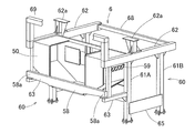
- the machine tool includes a machine tool main body 1, a loader device 2 that loads and unloads workpieces from the machine tool main body 1, a control panel 3 that controls the machine tool main body 1 and the loader device 2, and a machine tool main body. 1 and an operation panel 4 that operates the loader device 2, a cover 5 that covers the machine tool main body 1, and a cover support member 6 that supports the cover 5.
- the machine tool main body 1 is hidden by the cover 5.
- FIG. 2 shows a state in which a part of the cover 5 (the decorative cover 51) is removed.
- FIG. 3 shows the machine tool body 1.
- the machine tool main body 1 of this embodiment is a parallel twin-axis lathe, and includes two left and right beds 11 that are installed on the floor surface F independently of each other.
- a main spindle 12 and a tool post 13 are respectively installed.
- the main shaft 12 is an axis along the front-rear direction (Z-axis direction), and has a chuck 14 that grips a workpiece at the front end.
- the spindle 12 is rotatably supported by a spindle base 15 installed on the bed 11 and is rotationally driven by a spindle motor (not shown) installed on the spindle base 15.
- the tool post 13 is composed of, for example, a turret having a polygonal front surface, and a plurality of tools (not shown) are attached to the respective outer peripheral surface portions, so that any tool can be indexed by rotation.
- the tool post 13 is supported on a feed base 16 that is provided on the bed 11 and is movable in the front-rear direction (Z-axis direction) and the left-right direction (X-axis direction).
- the tool is applied to the workpiece W gripped by the chuck 14 of the rotating spindle 12 to process the workpiece.
- the feed base 16 By moving the feed base 16 in the front-rear direction, the tool is fed in the axial direction of the spindle 12, and by moving the feed base 16 in the left-right direction, the cutting amount of the work W by the tool is adjusted.
- the loader device 2 includes a material supply unit (not shown) and a product carry-out unit (not shown) installed on the left and right sides of the machine tool main body 1, and each spindle 12 of the machine tool main body 1. It is a device that delivers workpieces to and from.
- the loader device 2 of this embodiment is of a gantry type, and the loader 2A traveling on the traveling rail 22 grips the workpiece and moves in the left-right direction (X-axis direction) and the up-down direction (Y-axis direction) Transport the workpiece.
- the traveling rail 22 is installed horizontally above and below the machine tool main body 1, and the loader 22 ⁇ / b> A travels along the traveling rail 22 and moves up and down with respect to the traveling body 23.
- a loader head 21 that has a long lifting rod 24 at the top and bottom and that grips a workpiece by a loader chuck 20 is provided at the lower end of the lifting rod 24.
- the cover 5 covers a machining area cover 50 that surrounds the machining area Q, a bed 11 of the machine tool main body 1, a headstock 15 that is a supporting part of the spindle 12, and a makeup cover that covers a feed base 16 that is a supporting part of the tool rest 13. 51 and a pair of left and right sliding doors 52 provided on the front surface of the processing area Q.
- the machining area Q is an area where a workpiece is machined by the spindle 12 and the tool post 13 which are machining equipment.
- the processing area cover 50 has a box shape including a front plate portion 50a, a back plate portion 50b, left and right side plate portions 50c, a top plate portion 50d, and a bottom plate portion 50e.
- the left and right central portions of the front plate portion 50a, the top plate portion 50d, and the bottom plate portion 50e are cut out to form openings.
- the slide door 52 is attached to the opening 53 of the front plate portion 50a.
- the opening 54 of the upper surface plate portion 50d is for the loader head 21 of the loader 2A to enter and exit the processing region Q.
- the opening 55 of the bottom plate part 50e is for discharging chips generated by processing downward, and the bottom plate part 50e has a shape that becomes lower toward the center toward the opening 55. Further, windows 56 and 57 for opening a pair of left and right main shafts 12 and a tool post 13 so as to protrude from the rear into the processing region Q are opened in the back plate portion 50b.
- a rail member 58 that is long on the left and right to be the rail of the slide door 52 is fixed to the lower end portion of the front plate portion 50a. Both ends of the rail member 58 protrude to the left and right sides of the side plate portion 50 c, and the tip of the protruding portion is a lower supported portion 58 a that is supported by the cover support member 6.
- upper and lower supported members 59 supported by the cover support member 6 are provided on the left and right side plate portions 50c so as to protrude outward in the left and right directions.
- the upper supported member 59 is L-shaped with the front shape turned upside down, and a plurality of reinforcing ribs 59c are provided between the horizontal portion 59a and the vertical portion 59b.
- the decorative cover 51 includes a plurality of plate-like parts 51 a, 51 b, 51 c, and each plate-like part 51 a, 51 b, 51 c is attached to each part of the cover support member 6.
- Each plate-like part 51a, 51b, 51c will be described later.
- the pair of left and right sliding doors 52 have observation windows 52a and 52b made of a transparent material at the upper part and the upper and lower central parts, and are supported by the processing area cover 50 and the cover support member 6 so as to be slidable left and right. The supporting method will be described later.
- the cover support member 6 is installed without contact with each bed 11 of the machine tool body 1.
- the cover support member 6 includes a pair of left and right stands 60 installed on the floor surface F in an upright state.
- the left and right stands 60 include a pair of front and rear columns 61A and 61B extending in the vertical direction, a front and rear upper frame 62 fixedly supported on the upper ends of the pair of front and rear columns 61A and 61B, and an intermediate portion of the front column 61A.
- a lower frame 63 protruding forward, a connecting frame 64 that connects the upper frame 62 and the lower frame 63 to each other, and a first connecting plate 65 that is wide in the vertical direction that connects the lower portions of the front and rear columns 61A and 61B.
- the left and right stands 60 are respectively installed on the floor surface F by fixing the anchor plates 61a fixed to the lower ends of the columns 61A and 61B to the floor surface F with bolts 66.
- the front support columns 61 ⁇ / b> A are connected to each other by a second connecting plate 67 that is wide in the vertical direction, and the rear ends of the upper frames 62 extend in the left-right direction. Are connected to each other.
- rail mounts 62a on which the traveling rails 22 of the loader 2A are placed are provided on the upper surfaces of the upper frames 62 of the left and right stands 60, respectively.
- left and right leg portions 69a extending in the vertical direction are respectively fixed to the front ends of the front columns 61A of the left and right stands 60, and a front door-shaped slide door guide frame 69 is provided.
- the processing area cover 50 is supported by the cover support member 6 as shown in FIG. That is, the lower supported portions 58a which are the left and right ends of the rail member 58 are placed on the front end portion of the lower frame 63 of the cover supporting member 6, and the lower supported portions 58a and the lower front and rear frames 63 are bolted. Fix with etc. Further, the upper supported member 59 is applied to the lower surface of the upper frame 62, and the upper supported member 59 and the upper frame 62 are fixed with bolts or the like. Thereby, the left and right stands 60 of the cover support member 6 are connected to each other by the processing region cover 50 in addition to the connection by the second connection plate 67 and the control panel mounting frame 68.
- the structure in which the cover support member 6 and the processing area cover 50 are integrated has high rigidity. That is, the processing area cover 50 also serves as reinforcement of the cover support member 6.
- the machine tool main body 1 is configured such that each bed 11 is a floor surface so that each spindle base 15 (FIG. 3) and each feed base 16 (FIG. 3) are positioned on the rear side of the machining area cover 50. It is installed in a fixed state on F. Each bed 11 is not in contact with a structure including the cover support member 6 and the processing area cover 50.
- the main spindle 12 and the tool post 13 are projected into the machining area Q through the windows 56 and 57 of the machining area cover 50.
- a shielding cover 71 is fixedly attached to a gap between the main shaft 12 and the window 56 through which the main shaft 12 passes.
- a bellows-like cover 72 that expands and contracts according to the horizontal movement of the tool rest 13 is attached to a gap between the tool rest 13 in the window 57 through which the tool rest 13 passes.
- the traveling rail 22 of the loader 2 ⁇ / b> A is installed on the rail mount 62 a of the cover support member 6.
- the control panel 3 is installed on the control panel mounting frame 68 (FIGS. 5 and 6) of the cover support member 6.
- the operation panel 4 is attached to a turning fulcrum member 73 provided on the slide door guide frame 69 via a turning arm 74 so as to be turnable around a vertical axis.
- a chip receiving means 75 for receiving chips falling through the opening 55 (FIG. 4) of the bottom plate portion 50e of the processing area cover 50 is installed below the processing area cover 50.
- the chip receiving means 75 is a conveyer for conveying chips to a container for storing chips or a chip collecting unit installed separately from the machine tool.
- the decorative cover 51 has plate-like parts 51 a, 51 b, 51 c attached to each part of the cover support member 6. That is, the front plate-like part 51 a is attached to the connection frame 64 and the slide door guide frame 69 on the front side of the front plate portion 50 a of the processing area cover 50.
- the front plate-like part 51a is not attached to the front portion of the opening 53 of the front plate portion 50a, and is left open.
- Side plate-like parts 51 b are attached to the outer surfaces of the left and right stands 60. Between the rear columns 61B of the left and right stands 60, back plate-like parts (not shown) are attached.
- a front lower plate-like part 51c is attached so as to cover the rail member 58 of the processing region cover 50.
- the pair of left and right sliding doors 52 are mounted such that the lower ends are supported by the rail member 58 of the processing area cover 50 so as to be slidable left and right, and the upper ends are guided to the left and right by the sliding door guide frame 69 of the cover support member 6. .
- the front portion of the processing area Q can be opened and closed.
- the machine tool main body 1 is a parallel twin-axis lathe having two sets of processing devices.
- the beds 11 on which each set of processing devices is mounted are independent from each other, vibration caused by processing of one set of processing devices.
- it is not transmitted directly to the other set of processing equipment via the bed 11. Therefore, the internal and external vibrations of the machine do not affect the processing by the spindle 12 and the tool post 13 which are processing devices, and stable processing can be performed.
- cover support member 6 also serves as a support member for the travel rail 22 of the loader 2A, it is not necessary to provide a separate support member for the travel rail 22, and the configuration can be simplified.
- the cover 5 of this machine tool is separate from the box-shaped processing region cover 50 that surrounds the processing region Q and also serves as a reinforcement of the cover support member 6, and the spindle 11 and the feed base 16 that are the support portions of the bed 11 and processing equipment. Therefore, not only the processing area Q but the entire machine tool body 1 can be covered.
- the two beds 11 are directly installed on the floor surface F, respectively, but as shown in FIG. 7, the base member 80 is provided on the floor surface F, and each bed 11 is installed on the base member 80. May be. Also in this case, the cover support member 6 is installed without contact with the bed 11.
- the machine tool body 1 is not limited to a parallel twin-axis lathe. A lathe with three or more axes may be used. Moreover, machines other than a lathe may be used. Accordingly, such changes and modifications are to be construed as within the scope of the invention as defined by the appended claims.
Landscapes
- Engineering & Computer Science (AREA)
- Mechanical Engineering (AREA)
- Turning (AREA)
- Auxiliary Devices For Machine Tools (AREA)
- Feeding Of Workpieces (AREA)
- Machine Tool Units (AREA)
Abstract
Priority Applications (5)
| Application Number | Priority Date | Filing Date | Title |
|---|---|---|---|
| JP2013550190A JP5708825B2 (ja) | 2011-12-22 | 2012-11-26 | 工作機械 |
| KR1020147016798A KR20140100533A (ko) | 2011-12-22 | 2012-11-26 | 공작 기계 |
| CN201280060867.5A CN103987489A (zh) | 2011-12-22 | 2012-11-26 | 机床 |
| EP12859061.9A EP2796239A4 (fr) | 2011-12-22 | 2012-11-26 | Matériel d'usinage |
| US14/366,008 US20140319746A1 (en) | 2011-12-22 | 2012-11-26 | Machine tool |
Applications Claiming Priority (2)
| Application Number | Priority Date | Filing Date | Title |
|---|---|---|---|
| JP2011281062 | 2011-12-22 | ||
| JP2011-281062 | 2011-12-22 |
Publications (1)
| Publication Number | Publication Date |
|---|---|
| WO2013094367A1 true WO2013094367A1 (fr) | 2013-06-27 |
Family
ID=48668266
Family Applications (1)
| Application Number | Title | Priority Date | Filing Date |
|---|---|---|---|
| PCT/JP2012/080429 Ceased WO2013094367A1 (fr) | 2011-12-22 | 2012-11-26 | Matériel d'usinage |
Country Status (6)
| Country | Link |
|---|---|
| US (1) | US20140319746A1 (fr) |
| EP (1) | EP2796239A4 (fr) |
| JP (1) | JP5708825B2 (fr) |
| KR (1) | KR20140100533A (fr) |
| CN (1) | CN103987489A (fr) |
| WO (1) | WO2013094367A1 (fr) |
Cited By (6)
| Publication number | Priority date | Publication date | Assignee | Title |
|---|---|---|---|---|
| EP2848360A1 (fr) * | 2013-09-13 | 2015-03-18 | Dmg Mori Seiki Aktiengesellschaft | Machine-outil à commande numérique avec un élément de forme pour couvrir la base de la machine-outil. |
| KR20150121875A (ko) * | 2014-04-22 | 2015-10-30 | 두산인프라코어 주식회사 | 2개의 스핀들을 구비하는 공작기계 |
| WO2016063393A1 (fr) * | 2014-10-23 | 2016-04-28 | 富士機械製造株式会社 | Ligne de machines de traitement |
| WO2021235142A1 (fr) * | 2020-05-18 | 2021-11-25 | 村田機械株式会社 | Système de machine-outil |
| WO2022234620A1 (fr) * | 2021-05-06 | 2022-11-10 | ファナック株式会社 | Machine-outil |
| WO2023021649A1 (fr) * | 2021-08-19 | 2023-02-23 | ファナック株式会社 | Machine-outil |
Families Citing this family (26)
| Publication number | Priority date | Publication date | Assignee | Title |
|---|---|---|---|---|
| DE102011057093B4 (de) * | 2011-12-28 | 2015-12-31 | Rattunde & Co. Gmbh | Bearbeitungsvorrichtung für Enden von Langprofilabschnitten |
| JP1518369S (fr) * | 2013-09-13 | 2015-03-02 | ||
| CA154873S (en) * | 2014-01-24 | 2015-06-26 | Aonix Advanced Materials | Advanced composite material production machine |
| CN105328498A (zh) * | 2015-11-10 | 2016-02-17 | 芜湖天金机械有限公司 | 一种万向节球壳车铣加工传输系统 |
| ITUB20159554A1 (it) * | 2015-12-15 | 2017-06-15 | Prima Ind Spa | Cella di lavoro e centro per lavorazioni laser dotato di tale cella |
| USD799570S1 (en) * | 2015-12-15 | 2017-10-10 | Dmg Mori Co., Ltd. | Machining center |
| JP6707408B2 (ja) * | 2016-06-29 | 2020-06-10 | Dmg森精機株式会社 | マシニングセンター |
| TWD189090S (zh) * | 2016-09-09 | 2018-03-11 | 葛里森工具公司 | 金屬加工切割或研磨機 |
| TWD186171S (zh) * | 2016-09-09 | 2017-10-21 | 葛里森工具公司 | 計量機 |
| TWD187428S (zh) * | 2016-09-09 | 2017-12-21 | 葛里森工具公司 | 金屬加工切割或研磨機 |
| CN106424760B (zh) * | 2016-11-16 | 2018-11-23 | 江西奈尔斯西蒙斯赫根赛特中机有限公司 | 单轴至四轴组合式数控不落轮车床 |
| CN106514303A (zh) * | 2016-12-08 | 2017-03-22 | 廊坊精雕数控机床制造有限公司 | 一种具有平移交互工作台的双主轴数控机床 |
| CN106392760A (zh) * | 2016-12-08 | 2017-02-15 | 廊坊精雕数控机床制造有限公司 | 一种防护门可随加工区域移动的数控机床 |
| CN106425696A (zh) * | 2016-12-08 | 2017-02-22 | 廊坊精雕数控机床制造有限公司 | 一种平移交互工作台数控机床组成的自动化系统 |
| CN106624845A (zh) * | 2016-12-08 | 2017-05-10 | 廊坊精雕数控机床制造有限公司 | 一种平移交互工作台数控机床 |
| CN108326628A (zh) * | 2018-01-16 | 2018-07-27 | 宁夏共享机床辅机有限公司 | 一种具有精度保持作用的机床防护罩 |
| CN109015092B (zh) * | 2018-10-24 | 2020-10-30 | 安徽创弘精密机械有限公司 | 一种铁质零件与切屑分离装置 |
| USD938501S1 (en) * | 2019-01-11 | 2021-12-14 | Doosan Machine Tools Co., Ltd. | Machine center |
| USD932526S1 (en) * | 2019-01-11 | 2021-10-05 | Doosan Machine Tools Co., Ltd. | Machine center |
| USD932525S1 (en) * | 2019-01-11 | 2021-10-05 | Doosan Machine Tools Co., Ltd. | Machine center |
| USD918277S1 (en) * | 2019-06-07 | 2021-05-04 | Bühler AG | Die casting machine |
| USD923670S1 (en) * | 2020-06-22 | 2021-06-29 | Doosan Machine Tools Co., Ltd. | Machine center |
| CN112872888B (zh) * | 2021-01-08 | 2022-04-15 | 宁波天瑞精工机械有限公司 | 一种具有快换式过滤网板结构的数控机床的排屑过滤系统 |
| CN117680741B (zh) * | 2024-02-02 | 2024-05-03 | 靖江市东达新能源科技有限公司 | 一种电池铝盖板加工装置 |
| CN117862945A (zh) * | 2024-03-04 | 2024-04-12 | 安徽瑞苏科技有限公司 | 一种四工位专用机床 |
| JP1794400S (ja) * | 2024-07-30 | 2025-03-26 | 研磨及び研削機器 |
Citations (6)
| Publication number | Priority date | Publication date | Assignee | Title |
|---|---|---|---|---|
| JP2606511B2 (ja) | 1991-12-28 | 1997-05-07 | 村田機械株式会社 | 切削機械 |
| JP2003039271A (ja) * | 2001-07-27 | 2003-02-12 | Murata Mach Ltd | 工作機械 |
| JP2004142041A (ja) * | 2002-10-25 | 2004-05-20 | Mori Seiki Co Ltd | 工作機械の外装カバー |
| JP3719167B2 (ja) | 2001-06-18 | 2005-11-24 | 村田機械株式会社 | 工作機械 |
| JP2006068861A (ja) * | 2004-09-03 | 2006-03-16 | Okamoto Machine Tool Works Ltd | 工作機械の安全扉およびその設置方法 |
| WO2008029485A1 (fr) * | 2006-09-04 | 2008-03-13 | Makino Milling Machine Co., Ltd. | Pare-éclaboussures pour MACHINE-OUTIL |
Family Cites Families (17)
| Publication number | Priority date | Publication date | Assignee | Title |
|---|---|---|---|---|
| US4514936A (en) * | 1983-10-19 | 1985-05-07 | Hurtado Ruben G | Lathe dust enclosure |
| JPH024739U (fr) * | 1988-06-22 | 1990-01-12 | ||
| US5217335A (en) * | 1990-04-24 | 1993-06-08 | National Optronics, Inc. | Plastic lens generator and method |
| US5181898A (en) * | 1991-09-16 | 1993-01-26 | Cincinnati Milacron, Inc. | Cover assembly for multi-configurable machine tool |
| US5263800A (en) * | 1992-08-20 | 1993-11-23 | Chen Chih Hung | Work table of tooling machine |
| US5265497A (en) * | 1992-09-08 | 1993-11-30 | Cincinnati Milacron Inc. | Guard for operator access station |
| US5662568A (en) * | 1995-05-12 | 1997-09-02 | Ingersoll Milling Machine Co. | Symmetrical multi-axis linear motor machine tool |
| DE19918359C2 (de) * | 1999-04-22 | 2002-10-31 | Deckel Maho Gmbh | Werkzeugmaschine mit einer Arbeitsraumabdeckung |
| DE19956900B4 (de) * | 1999-11-26 | 2005-09-08 | Stama Maschinenfabrik Gmbh | Werkzeugmaschine mit Faltenbalg-Dachabdeckung |
| JP3952161B2 (ja) * | 2002-03-26 | 2007-08-01 | ブラザー工業株式会社 | 工作機械 |
| JP4768257B2 (ja) * | 2004-12-21 | 2011-09-07 | 株式会社岡本工作機械製作所 | 工作機械の全閉カバ−装置 |
| US7172375B2 (en) * | 2005-06-23 | 2007-02-06 | Mori Seiki Co., Ltd. | Machine tool |
| EP1754568A1 (fr) * | 2005-08-19 | 2007-02-21 | Mikron Agie Charmilles AG | Machine-outil avec fermeture automatique sur le toit |
| DE502005004017D1 (de) * | 2005-08-19 | 2008-06-19 | Mikron Agie Charmilles Ag | Werkzeugmaschine mit Faltenbalgabdeckung |
| DE202006000543U1 (de) * | 2006-01-14 | 2006-03-09 | Gebr. Heller Maschinenfabrik Gmbh | Werkzeugmaschine mit Handhabungseinrichtung |
| CN200945560Y (zh) * | 2006-09-27 | 2007-09-12 | 成都宁江机床(集团)股份有限公司 | 立式五轴联动加工中心 |
| JP4966670B2 (ja) * | 2007-01-11 | 2012-07-04 | 株式会社森精機製作所 | 工作機械 |
-
2012
- 2012-11-26 CN CN201280060867.5A patent/CN103987489A/zh active Pending
- 2012-11-26 EP EP12859061.9A patent/EP2796239A4/fr not_active Withdrawn
- 2012-11-26 KR KR1020147016798A patent/KR20140100533A/ko not_active Ceased
- 2012-11-26 WO PCT/JP2012/080429 patent/WO2013094367A1/fr not_active Ceased
- 2012-11-26 JP JP2013550190A patent/JP5708825B2/ja active Active
- 2012-11-26 US US14/366,008 patent/US20140319746A1/en not_active Abandoned
Patent Citations (7)
| Publication number | Priority date | Publication date | Assignee | Title |
|---|---|---|---|---|
| JP2606511B2 (ja) | 1991-12-28 | 1997-05-07 | 村田機械株式会社 | 切削機械 |
| JP3719167B2 (ja) | 2001-06-18 | 2005-11-24 | 村田機械株式会社 | 工作機械 |
| JP2003039271A (ja) * | 2001-07-27 | 2003-02-12 | Murata Mach Ltd | 工作機械 |
| JP4400011B2 (ja) | 2001-07-27 | 2010-01-20 | 村田機械株式会社 | 工作機械 |
| JP2004142041A (ja) * | 2002-10-25 | 2004-05-20 | Mori Seiki Co Ltd | 工作機械の外装カバー |
| JP2006068861A (ja) * | 2004-09-03 | 2006-03-16 | Okamoto Machine Tool Works Ltd | 工作機械の安全扉およびその設置方法 |
| WO2008029485A1 (fr) * | 2006-09-04 | 2008-03-13 | Makino Milling Machine Co., Ltd. | Pare-éclaboussures pour MACHINE-OUTIL |
Non-Patent Citations (1)
| Title |
|---|
| See also references of EP2796239A4 |
Cited By (17)
| Publication number | Priority date | Publication date | Assignee | Title |
|---|---|---|---|---|
| CN105612026B (zh) * | 2013-09-13 | 2019-08-06 | 德马吉森股份公司 | 数控机床 |
| US10071453B2 (en) | 2013-09-13 | 2018-09-11 | Dmg Mori Aktiengesellschaft | Numerically controlled machine tool |
| EP2848360A1 (fr) * | 2013-09-13 | 2015-03-18 | Dmg Mori Seiki Aktiengesellschaft | Machine-outil à commande numérique avec un élément de forme pour couvrir la base de la machine-outil. |
| WO2015036488A1 (fr) * | 2013-09-13 | 2015-03-19 | Dmg Mori Seiki Aktiengesellschaft | Machine-outil à commande numérique |
| CN105612026A (zh) * | 2013-09-13 | 2016-05-25 | 德马吉森股份公司 | 数控机床 |
| JP2016531013A (ja) * | 2013-09-13 | 2016-10-06 | ディエムジー・モリ・アクチェンゲゼルシャフトDmg Mori Aktiengesellschaft | 数値制御工作機械 |
| KR102231352B1 (ko) * | 2014-04-22 | 2021-03-24 | 두산공작기계 주식회사 | 2개의 스핀들을 구비하는 공작기계 |
| KR20150121875A (ko) * | 2014-04-22 | 2015-10-30 | 두산인프라코어 주식회사 | 2개의 스핀들을 구비하는 공작기계 |
| JPWO2016063393A1 (ja) * | 2014-10-23 | 2017-08-03 | 富士機械製造株式会社 | 加工機械ライン |
| WO2016063393A1 (fr) * | 2014-10-23 | 2016-04-28 | 富士機械製造株式会社 | Ligne de machines de traitement |
| WO2021235142A1 (fr) * | 2020-05-18 | 2021-11-25 | 村田機械株式会社 | Système de machine-outil |
| JPWO2021235142A1 (fr) * | 2020-05-18 | 2021-11-25 | ||
| KR20230002804A (ko) * | 2020-05-18 | 2023-01-05 | 무라다기카이가부시끼가이샤 | 공작 기계 시스템 |
| JP7371774B2 (ja) | 2020-05-18 | 2023-10-31 | 村田機械株式会社 | 工作機械システム |
| KR102743825B1 (ko) | 2020-05-18 | 2024-12-18 | 무라다기카이가부시끼가이샤 | 공작 기계 시스템 |
| WO2022234620A1 (fr) * | 2021-05-06 | 2022-11-10 | ファナック株式会社 | Machine-outil |
| WO2023021649A1 (fr) * | 2021-08-19 | 2023-02-23 | ファナック株式会社 | Machine-outil |
Also Published As
| Publication number | Publication date |
|---|---|
| EP2796239A1 (fr) | 2014-10-29 |
| US20140319746A1 (en) | 2014-10-30 |
| JPWO2013094367A1 (ja) | 2015-04-27 |
| KR20140100533A (ko) | 2014-08-14 |
| CN103987489A (zh) | 2014-08-13 |
| JP5708825B2 (ja) | 2015-04-30 |
| EP2796239A4 (fr) | 2015-07-29 |
Similar Documents
| Publication | Publication Date | Title |
|---|---|---|
| JP5708825B2 (ja) | 工作機械 | |
| JP4958300B2 (ja) | 工作機械 | |
| JP2009113170A5 (fr) | ||
| EP2283966B1 (fr) | Machine-outil | |
| JP5605502B2 (ja) | 工作機械システム | |
| EP2060360B1 (fr) | Pare-éclaboussures pour machine-outil | |
| JP6199511B1 (ja) | 複合加工装置及び複合加工方法 | |
| WO2018047301A1 (fr) | Machine-outil | |
| JP2014058032A (ja) | 保護カバーを有する工作機械 | |
| JP2013094957A (ja) | Y軸線を有する工作機械 | |
| CN104411452B (zh) | 机床 | |
| CN104411453B (zh) | 机床 | |
| JP2009178831A (ja) | ローダ装置 | |
| JP2010247328A (ja) | 工作機械 | |
| JP4092948B2 (ja) | ロボットを用いた加工システム及び加工方法 | |
| JP2024074429A (ja) | 横型加工機及び横型加工システム | |
| JP2011245563A (ja) | 工作機械 | |
| JP4522684B2 (ja) | 工作機械 | |
| JP2001300827A (ja) | マシニングセンタ | |
| JP3181360U (ja) | 工作機械 | |
| JP5201473B2 (ja) | 工作機械の機体カバー | |
| JP2013021018A (ja) | 切削装置ユニット | |
| JP2026065974A (ja) | 工作機械 | |
| JP2004223683A (ja) | 工作機械 | |
| JP2005297085A (ja) | 工作機械 |
Legal Events
| Date | Code | Title | Description |
|---|---|---|---|
| 121 | Ep: the epo has been informed by wipo that ep was designated in this application |
Ref document number: 12859061 Country of ref document: EP Kind code of ref document: A1 |
|
| ENP | Entry into the national phase |
Ref document number: 2013550190 Country of ref document: JP Kind code of ref document: A |
|
| WWE | Wipo information: entry into national phase |
Ref document number: 14366008 Country of ref document: US |
|
| ENP | Entry into the national phase |
Ref document number: 20147016798 Country of ref document: KR Kind code of ref document: A |
|
| REEP | Request for entry into the european phase |
Ref document number: 2012859061 Country of ref document: EP |
|
| WWE | Wipo information: entry into national phase |
Ref document number: 2012859061 Country of ref document: EP |
|
| NENP | Non-entry into the national phase |
Ref country code: DE |