WO2013100123A1 - Feuille isolante et thermiquement conductrice - Google Patents
Feuille isolante et thermiquement conductrice Download PDFInfo
- Publication number
- WO2013100123A1 WO2013100123A1 PCT/JP2012/084055 JP2012084055W WO2013100123A1 WO 2013100123 A1 WO2013100123 A1 WO 2013100123A1 JP 2012084055 W JP2012084055 W JP 2012084055W WO 2013100123 A1 WO2013100123 A1 WO 2013100123A1
- Authority
- WO
- WIPO (PCT)
- Prior art keywords
- insulating
- fiber
- heat conductive
- sheet
- conductive sheet
- Prior art date
- Legal status (The legal status is an assumption and is not a legal conclusion. Google has not performed a legal analysis and makes no representation as to the accuracy of the status listed.)
- Ceased
Links
Images


Classifications
-
- H—ELECTRICITY
- H05—ELECTRIC TECHNIQUES NOT OTHERWISE PROVIDED FOR
- H05K—PRINTED CIRCUITS; CASINGS OR CONSTRUCTIONAL DETAILS OF ELECTRIC APPARATUS; MANUFACTURE OF ASSEMBLAGES OF ELECTRICAL COMPONENTS
- H05K7/00—Constructional details common to different types of electric apparatus
- H05K7/20—Modifications to facilitate cooling, ventilating, or heating
- H05K7/2039—Modifications to facilitate cooling, ventilating, or heating characterised by the heat transfer by conduction from the heat generating element to a dissipating body
- H05K7/20436—Inner thermal coupling elements in heat dissipating housings, e.g. protrusions or depressions integrally formed in the housing
- H05K7/20445—Inner thermal coupling elements in heat dissipating housings, e.g. protrusions or depressions integrally formed in the housing the coupling element being an additional piece, e.g. thermal standoff
- H05K7/20472—Sheet interfaces
- H05K7/20481—Sheet interfaces characterised by the material composition exhibiting specific thermal properties
-
- B—PERFORMING OPERATIONS; TRANSPORTING
- B05—SPRAYING OR ATOMISING IN GENERAL; APPLYING FLUENT MATERIALS TO SURFACES, IN GENERAL
- B05D—PROCESSES FOR APPLYING FLUENT MATERIALS TO SURFACES, IN GENERAL
- B05D5/00—Processes for applying liquids or other fluent materials to surfaces to obtain special surface effects, finishes or structures
-
- B—PERFORMING OPERATIONS; TRANSPORTING
- B29—WORKING OF PLASTICS; WORKING OF SUBSTANCES IN A PLASTIC STATE IN GENERAL
- B29C—SHAPING OR JOINING OF PLASTICS; SHAPING OF MATERIAL IN A PLASTIC STATE, NOT OTHERWISE PROVIDED FOR; AFTER-TREATMENT OF THE SHAPED PRODUCTS, e.g. REPAIRING
- B29C70/00—Shaping composites, i.e. plastics material comprising reinforcements, fillers or preformed parts, e.g. inserts
- B29C70/04—Shaping composites, i.e. plastics material comprising reinforcements, fillers or preformed parts, e.g. inserts comprising reinforcements only, e.g. self-reinforcing plastics
- B29C70/28—Shaping operations therefor
- B29C70/30—Shaping by lay-up, i.e. applying fibres, tape or broadsheet on a mould, former or core; Shaping by spray-up, i.e. spraying of fibres on a mould, former or core
- B29C70/38—Automated lay-up, e.g. using robots, laying filaments according to predetermined patterns
- B29C70/382—Automated fiber placement [AFP]
-
- B—PERFORMING OPERATIONS; TRANSPORTING
- B29—WORKING OF PLASTICS; WORKING OF SUBSTANCES IN A PLASTIC STATE IN GENERAL
- B29C—SHAPING OR JOINING OF PLASTICS; SHAPING OF MATERIAL IN A PLASTIC STATE, NOT OTHERWISE PROVIDED FOR; AFTER-TREATMENT OF THE SHAPED PRODUCTS, e.g. REPAIRING
- B29C70/00—Shaping composites, i.e. plastics material comprising reinforcements, fillers or preformed parts, e.g. inserts
- B29C70/88—Shaping composites, i.e. plastics material comprising reinforcements, fillers or preformed parts, e.g. inserts characterised primarily by possessing specific properties, e.g. electrically conductive or locally reinforced
-
- H—ELECTRICITY
- H10—SEMICONDUCTOR DEVICES; ELECTRIC SOLID-STATE DEVICES NOT OTHERWISE PROVIDED FOR
- H10W—GENERIC PACKAGES, INTERCONNECTIONS, CONNECTORS OR OTHER CONSTRUCTIONAL DETAILS OF DEVICES COVERED BY CLASS H10
- H10W40/00—Arrangements for thermal protection or thermal control
- H10W40/20—Arrangements for cooling
- H10W40/25—Arrangements for cooling characterised by their materials
- H10W40/251—Organics
-
- H—ELECTRICITY
- H10—SEMICONDUCTOR DEVICES; ELECTRIC SOLID-STATE DEVICES NOT OTHERWISE PROVIDED FOR
- H10W—GENERIC PACKAGES, INTERCONNECTIONS, CONNECTORS OR OTHER CONSTRUCTIONAL DETAILS OF DEVICES COVERED BY CLASS H10
- H10W40/00—Arrangements for thermal protection or thermal control
- H10W40/20—Arrangements for cooling
- H10W40/25—Arrangements for cooling characterised by their materials
- H10W40/255—Arrangements for cooling characterised by their materials having a laminate or multilayered structure, e.g. direct bond copper [DBC] ceramic substrates
-
- H—ELECTRICITY
- H10—SEMICONDUCTOR DEVICES; ELECTRIC SOLID-STATE DEVICES NOT OTHERWISE PROVIDED FOR
- H10W—GENERIC PACKAGES, INTERCONNECTIONS, CONNECTORS OR OTHER CONSTRUCTIONAL DETAILS OF DEVICES COVERED BY CLASS H10
- H10W40/00—Arrangements for thermal protection or thermal control
- H10W40/20—Arrangements for cooling
- H10W40/25—Arrangements for cooling characterised by their materials
- H10W40/257—Arrangements for cooling characterised by their materials having a heterogeneous or anisotropic structure, e.g. powder or fibres in a matrix, wire mesh or porous structures
-
- B—PERFORMING OPERATIONS; TRANSPORTING
- B05—SPRAYING OR ATOMISING IN GENERAL; APPLYING FLUENT MATERIALS TO SURFACES, IN GENERAL
- B05D—PROCESSES FOR APPLYING FLUENT MATERIALS TO SURFACES, IN GENERAL
- B05D1/00—Processes for applying liquids or other fluent materials
- B05D1/16—Flocking otherwise than by spraying
-
- Y—GENERAL TAGGING OF NEW TECHNOLOGICAL DEVELOPMENTS; GENERAL TAGGING OF CROSS-SECTIONAL TECHNOLOGIES SPANNING OVER SEVERAL SECTIONS OF THE IPC; TECHNICAL SUBJECTS COVERED BY FORMER USPC CROSS-REFERENCE ART COLLECTIONS [XRACs] AND DIGESTS
- Y10—TECHNICAL SUBJECTS COVERED BY FORMER USPC
- Y10T—TECHNICAL SUBJECTS COVERED BY FORMER US CLASSIFICATION
- Y10T428/00—Stock material or miscellaneous articles
- Y10T428/24—Structurally defined web or sheet [e.g., overall dimension, etc.]
- Y10T428/24355—Continuous and nonuniform or irregular surface on layer or component [e.g., roofing, etc.]
Definitions
- the present invention relates to an insulating high thermal conductive sheet that is electrically insulating and has high heat dissipation. More specifically, the present invention relates to an insulating high thermal conductive sheet capable of efficiently diffusing heat from heating elements such as an electronic board, a semiconductor chip, and a light source while ensuring insulation reliability.
- Patent Documents 1 to 3 in order to solve the problem of insufficient heat conductivity, an invention has been made in which insulating heat conductive fibers are arranged in the heat conduction direction to efficiently conduct heat (see, for example, Patent Documents 1 to 3). ).
- Patent Document 1 and Patent Document 2 insulating high thermal conductive fibers are cast onto the planted layer by electrostatic flocking, and after solidifying the planted layer, the insulated high thermal conductive fibers are oriented upright in the sheet thickness direction by impregnating the binder resin.
- a method for manufacturing an insulating high thermal conductive sheet There has been proposed a method for manufacturing an insulating high thermal conductive sheet.
- Patent Document 3 proposes a method of manufacturing by orienting fibers in a binder resin by applying a magnetic field to the binder resin to which insulated high thermal conductive fibers are added, and solidifying the fibers.
- the inventions according to Patent Documents 1 to 3 are improved in that the thermal conductivity can be obtained efficiently with a small amount of filler, the filler cannot be filled at a high density, and sufficient thermal conductivity is obtained. It was a problem in that it was not possible.
- Non-Patent Document 1 records the results of electrostatic flocking using nylon fibers having a fineness of 1.5d and a fiber length of 0.5 mm at a density of 94700 / cm2, that is, a density of 14%.
- Patent Document 4 states that in general electrostatic flocking technology, the flocking basis weight is generally about 100 to 150 g / m 2 regardless of the thickness and length of the flocked short fibers. Yes. For example, when short fibers having a density of 1.2 g / cm 3 and a fiber length of 0.4 mm are used, the short fiber volume with respect to the entire sheet volume corresponds to 30%. Thus, in the above-mentioned document, high-density electrostatic flocking is possible. However, the conventional electrostatic flocking described in Non-Patent Document 5 is generally used as a technique for producing raised materials used for clothes, carpets, heat insulating materials, etc., and extreme uprightness of fibers is not required. It also contains a lot of fibers that are greatly inclined. Therefore, when an insulated high thermal conductive sheet is manufactured using the conventional electrostatic flocking technique, since the inclined fiber cannot penetrate in the thickness direction of the sheet, a high penetration density cannot be obtained.
- the present invention has been made against the background of the problems of the prior art. That is, the objective of this invention is providing the heat conductive sheet excellent in insulation and heat conductivity.
- this invention consists of the following structures.
- the insulating heat conductive sheet according to 1, wherein an average value of the inclination of the insulating high heat conductive fiber penetrating in the thickness direction with respect to the sheet surface is 60 ° or more and 90 ° or less. 3.
- the insulating high thermal conductive fiber penetrating in the thickness direction protrudes to a length of 50 ⁇ m or more and 1000 ⁇ m or less on the opposite surface (B surface) of the smooth surface (A surface) having a surface roughness of 15 ⁇ m or less. 4.
- a process of erecting insulating high thermal conductive short fibers by electrostatic flocking on a base material coated with an adhesive comprising:
- the present invention it is possible to quickly release heat from a heating element such as a semiconductor or an LED while ensuring insulation reliability. As a result, damage due to heat in an electronic device or a light source can be reduced.
- Example of manufacturing method of insulating heat conductive sheet in the present invention Graph illustrating preferred manufacturing conditions in the present invention
- the insulating high thermal conductive sheet in the present invention contains an insulating high thermal conductive fiber penetrating in the thickness direction and a binder resin. Insulating high thermal conductive fibers penetrating in the thickness direction move the heat generated from the heating element to the opposite surface of the sheet and transfer it to the air or the coolant.
- the insulating high thermal conductive sheet in the present invention needs to have a smooth sheet surface on at least one surface of the sheet. By being smooth, the insulating high thermal conductive fiber can be in close contact with the heat generating surface and efficiently conduct heat. Further, when a coolant is installed on the opposite surface of the smooth surface, the opposite surface needs to be smooth in order to adhere to the coolant and efficiently conduct heat.
- the durometer hardness of the insulating high thermal conductive sheet in the present invention is preferably a Shore A hardness of 80 or less and a Shore E hardness of 5 or more, more preferably a Shore A hardness of 70 or less and a Shore E hardness of 10 or more. If the Shore A hardness is low, it is possible to make close contact along the slight irregularities of the heating element and the heat dissipation element, thereby enabling efficient heat conduction. On the other hand, if the Shore E hardness is high, the handling property when incorporated into an electronic device or a light source becomes good.
- the volume resistivity of the insulating high thermal conductive sheet in the present invention is 10 10 ⁇ ⁇ cm or more, preferably 10 12 ⁇ ⁇ cm or more, more preferably 10 13 ⁇ ⁇ cm or more. If the volume resistivity is high, it can be suitably used for applications that require high insulation reliability, such as around power supplies.
- the upper limit value of the volume resistivity is not particularly limited, but is about 10 16 ⁇ ⁇ cm.
- the flame retardancy of the insulating high thermal conductive sheet in the present invention is preferably equivalent to V-0. If it is equivalent to V-0, it is possible to reduce the spread of fire when it is ignited due to short circuit or deterioration of the circuit in the electronic device.
- the thermal conductivity and insulation in the thickness direction of the insulating high thermal conductive sheet in the present invention are achieved by selecting an insulating high thermal conductive fiber penetrating in the thickness direction and an insulating binder resin that supports it, and a manufacturing method described later.
- the thickness of the sheet is preferably 10 ⁇ m or more and 300 ⁇ m or less, and more preferably 50 ⁇ m or more and 80 ⁇ m or less. If the thickness is less than 10 ⁇ m, the strength of the sheet is lowered, and the handling property is deteriorated. On the other hand, if it exceeds 300 ⁇ m, the thermal resistance increases, which is not preferable.
- the insulating high thermal conductive fiber is not particularly specified as long as it has electrical insulation and high thermal conductivity, and examples thereof include boron nitride fiber, high-strength polyethylene fiber, and polybenzazole fiber.
- a polybenzazole fiber that combines properties and is readily available is preferred. Carbon fiber has high thermal conductivity but is electrically conductive, so it is not suitable for use in the present invention from the viewpoint of electrical insulation.
- the polybenzazole fiber can be purchased as a commercial product (Zylon manufactured by Toyobo Co., Ltd.).
- the thermal conductivity of the insulated high thermal conductive fiber is preferably 20 W / mK or more, more preferably 30 W / mK or more. When the thermal conductivity is 20 W / mK or more, high thermal conductivity is obtained when it is formed into a sheet.
- the volume specific resistance of the insulating high thermal conductive fiber is preferably 10 10 ⁇ ⁇ cm or more, preferably 10 12 ⁇ ⁇ cm, more preferably 10 13 ⁇ ⁇ cm. Since the volume resistivity of the insulating high thermal conductive fiber is almost equal to the volume resistivity of the sheet, a high volume resistivity is required.
- the insulating high thermal conductive fiber may have any cross-sectional shape, but a circular shape is preferable because it is easy to increase the penetration density. Although a diameter is not specifically limited, 1 mm or less is preferable from the surface of the uniformity of the heat dissipation object.
- the binder resin is preferably excellent in heat resistance, electrical insulation, and thermal stability. By appropriately selecting the binder resin, these physical properties can be adjusted to a desired range. In consideration of adhesion to the heating element, it is preferable to select a resin having excellent flexibility or a resin having adhesiveness.
- materials having excellent flexibility include silicone resins, acrylic resins, urethane resins, EPDM, and polycarbonate resins, and examples of materials having adhesive properties include semi-cured thermosetting resins.
- a material excellent in flexibility a silicone resin that is less susceptible to deterioration due to a change in physical properties due to heat cycle is particularly preferable.
- the material having adhesiveness is preferably a urethane-based resin having good shock absorption from the viewpoint of thermal shock resistance at the bonding interface with the heating element. It is also possible to impart flame retardancy to the heat conductive sheet by selecting a flame retardant material.
- the penetration density of the fiber needs to be 6% or more, preferably 6% or more and 50% or less, and more preferably 10% or more and 40% or less. If it is 6% or less, the thermal conductivity in the sheet thickness direction is undesirably lowered. If it is 50% or more, the strength of the sheet is lowered, and the handling properties are deteriorated, which is not preferable.
- the flocked fiber density in the present invention can be evaluated by the method of Examples described later.
- the fiber length is adjusted according to the thickness of the sheet and penetrates in the thickness direction of the sheet.
- the protruding length of the insulating high thermal conductive fiber penetrating in the thickness direction protruding on the opposite surface is preferably 10 ⁇ m or more and 1000 ⁇ m or less. By being 10 ⁇ m or more, the surface area is increased and heat can be efficiently transferred to the air.
- the thickness is 1000 ⁇ m, the temperature does not reach the fiber tip and the heat dissipation characteristics are not improved any more, which is disadvantageous in terms of cost.
- the protruding fibers are preferably coated with a resin containing a heat radiation agent such as carbon black for the purpose of providing heat dissipation characteristics.
- the protruding amount of the fiber on the smooth surface of the sheet and its variation can be evaluated by the surface roughness of the sheet, and the average surface roughness is preferably 4 ⁇ m or less.
- the average surface roughness is 4 ⁇ m or more, the fibers fall asleep after being bonded to the heat generator and the heat radiating body, and the heat radiation amount is reduced.
- the adhesiveness with a heat generating body and a heat radiator is impaired, heat dissipation falls.
- the sheet of the present invention may be in a state where an adhesive is applied to the surface thereof.
- the adhesive is not particularly limited, and examples thereof include acrylic ester resins, epoxy resins, silicone resins, and resins obtained by mixing high thermal conductive fillers such as metals, ceramics, and graphite in these resins.
- the insulating high thermal conductive sheet of the present invention can be produced by a method including the following steps.
- (i) The process of standing insulating high thermal conductive short fibers upright by electrostatic flocking on the base material coated with adhesive (ii) A step of shrinking the base material by adhering upright insulating high thermal conductive short fibers by heating, preferably while adhering or adhering (iii) a step of impregnating the insulating high thermal conductive short fibers fixed upright on the substrate with the binder resin to cure the binder resin (iv) A process of removing both surfaces or polishing both surfaces as they are
- Electrostatic flocking is a method in which a base material is placed on one side of two electrodes, and short fibers are placed on the other side. By applying a high voltage, the short fibers are charged and cast on the base material side and fixed by an adhesive. .
- the material of the adhesive in the above process is not particularly limited because it can be removed in a subsequent polishing process, but a lower insulating property is preferable in that electrostatic flocking can be performed at a high density.
- an acrylic resin aqueous dispersion is preferably used.
- the binder resin may be used as it is.
- the coating thickness of the adhesive is small in order to increase electrostatic attraction, but it is necessary to be large enough to fix the thrown fiber, The thickness is preferably 10 ⁇ m or more and 50 ⁇ m or less, more preferably 10 ⁇ m or more and 30 ⁇ m or less.
- the base material of the present invention is preferably made of a material having low electrical insulation in order to increase electrostatic attraction.
- a material capable of peeling the sheet after solidifying the binder For example, a metal foil, a polyethylene terephthalate film coated with a conductive agent, or a graphite sheet can be used.
- a shrinkable film For example, a shrinkable polystyrene film or a polyethylene terephthalate film coated with a conductive agent can be used.
- a grinding machine for the polishing in the present invention, a grinding machine, a polishing machine, a lapping machine, a polishing machine, a honing machine, a buffing machine, a CMP apparatus, or the like can be used. Even if it peels from a base material and polishes, or it polishes including a base material as it is, it can manufacture.
- the surface roughness of the smooth surface and the protruding length of the fiber from which the insulating high thermal conductive fiber protrudes can be controlled by the grain size of the polishing wheel or polishing paper.
- the appropriate particle size varies depending on the material used for the binder resin and the high thermal conductive fiber to be used, but if the particle size is lowered, the smoothness is improved, and if the particle size is lowered, the fiber is cut and the protruding length becomes longer.
- a polybenzazole fiber is used as the insulating high thermal conductive fiber, a smooth surface having a particle size of # 2000 or more and a surface roughness of 4 ⁇ m or less is obtained, and when the particle size is # 400 or less, the protrusion length is 10 ⁇ m or more, and the particle size is further reduced. This makes it possible to increase the protruding length.
- the electrostatic flocking in the present invention is preferably performed by an electrostatic flocking method capable of obtaining a high flocking density, and an up method is preferred.
- an electrostatic flocking method capable of obtaining a high flocking density
- an up method is preferred.
- the down method short fibers that naturally fall by gravity are planted in addition to the short fibers that are attracted to the counter electrode along the lines of electric force by electrostatic attraction, so that the uprightness of the fibers is poor.
- infiltration of another fiber is prevented by the fibers that are planted at an inclination, so that it is difficult to plant at a high density.
- the up method has good uprightness because only short fibers attracted by electrostatic attraction are implanted, and can be implanted at high density.
- performing electrostatic flocking with a high flocking density and maintaining the uprightness of the fibers is a manufacturing point for achieving high thermal conductivity.
- the average value of the inclination of the insulating high thermal conductive fibers penetrating in the thickness direction with respect to the sheet surface is 60 ° or more and 90 ° or less, preferably 65 ° or more and 90 ° or less, and more preferably 70 ° or more and 90 ° or less.
- the average value in the ratio of the thermal conductivity in the thickness direction and the plane direction of the insulating high thermal conductive sheet of the present invention is preferably 2 or more, more preferably 6 or more. By controlling to the above-mentioned angle, the ratio of the thermal conductivity can be ensured.
- the thermal anisotropy is high, that is, the orientation direction of the insulating high thermal conductive fiber is high, and even a relatively small amount of high thermal conductive fiber can be used. It is preferable that high thermal conductivity can be expressed in the thickness direction.
- the amount of insulating heat conductive fibers the interface between the binder resin and the fibers is reduced. As a result, when thermal stress or external impact is applied during use, peeling at these interfaces is unlikely to occur, resulting in long-term durability. An excellent sheet can be obtained.
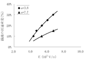
- the product E of the inter-electrode distance r (cm) and the applied voltage V (kV) of the electrostatic flocking in the present invention is preferably within the range of the formula 1, and the fiber length (mm) and the fineness of the insulated high thermal conductive fiber
- the quotient a of (D) is preferably within the range of Formula 2. If E is equal to or less than the range of Formula 1, the electric field strength is insufficient and high density hair transplantation cannot be performed. When E is 8 or more, dielectric breakdown occurs and electrostatic flocking cannot be performed normally. When a is 1.5 or less, the aspect ratio of the fiber becomes large, and it becomes difficult to maintain uprightness by its own weight.
- the flocking density can be controlled by adjusting E according to the applied voltage and the distance between the electrodes.
- a calibration curve of E and fiber penetration density is prepared in advance as shown in FIG. 4 and the flocking density can be controlled by electrostatic flocking at E suitable for the desired flocking density, that is, the fiber penetration density.
- the step of curing the binder resin by impregnating the insulating high thermal conductive fibers fixed upright on the base material with the binder resin can be performed by any of the following methods.
- a method in which a binder resin is dissolved in some solvent or impregnated in an emulsion state, and the solvent is evaporated and solidified by heating (ii) a method in which the binder resin is melted by heating and is cured by cooling; and (iii) A method of impregnation in the state of monomer and heating or curing with energy rays such as ultraviolet rays, infrared rays or electron beams.
- the evaluation method of various physical properties in the present invention is as follows.
- Fineness (denier) weight (g) x 90000
- the fiber length of the insulating high thermal conductive short fiber was observed with a short fiber test piece under a microscope, and was an average value of 100 test pieces.
- the fiber diameter of the insulating high heat conductive short fiber was observed with a short fiber specimen under a microscope, and the average fiber diameter at the center point in the fiber length direction was 10 specimens.
- the thermal conductivity in the fiber axis direction of the insulated high thermal conductive fiber was measured by a steady heat flow method in a system having a temperature control device with a helium refrigerator.
- the length of the sample fiber was about 25 mm, and the fiber bundle was bundled by drawing about 1000 single fibers.
- both ends of the sample fiber were fixed with stycast GT and set on a sample stage.
- An Au-chromel thermocouple was used for temperature measurement.
- a 1 k ⁇ resistor was used as the heater, and this was bonded to the end of the fiber bundle with varnish.
- the measurement temperature range was 27 ° C.
- the measurement was performed in a vacuum of 10 ⁇ 3 Pa in order to maintain heat insulation.
- the measurement was started after 24 hours had elapsed in a vacuum state of 10 ⁇ 3 Pa to bring the sample into a dry state.
- the thermal conductivity was measured by passing a constant current through the heater so that the temperature difference ⁇ T between the two points L was 1K. This is shown in FIG.
- the obtained thermal conductivity ⁇ is calculated by the following formula: can do. Examples measured using this experimental method are shown below.
- ⁇ (W / mK) (Q / ⁇ T) ⁇ (L / S)
- the volume resistivity of the insulating high thermal conductive fiber was measured by the following method.
- the long fiber bundle was dried at 105 ° C. for 1 hour, and then allowed to stand for 24 hours or more in an atmosphere of 25 ° C. and 30 RH% to adjust the humidity.
- a digital multimeter (R6441 manufactured by ADVANTEST) with a positive electrode and a ground electrode in contact with the superfiber bundle with a fixed length (5cm, 10cm, 15cm, 20cm), and a voltage of 10V applied between both electrodes. was used to measure the resistance value ( ⁇ ). From this resistance value, a volume specific resistance value was obtained for the length of each interval according to the following calculation formula, and the average value was used as the volume specific resistance value of the sample.
- ⁇ R ⁇ (S / L) ⁇ is the volume resistivity ( ⁇ cm), R is the resistance value ( ⁇ ) of the test piece, S is the cross-sectional area (cm2), and L is the length (2 cm).
- the cross-sectional area of the test piece was calculated by observing the fiber under a microscope.
- the density of the sheet and fiber was measured with a dry automatic densimeter (manufactured by Shimadzu Corp. Accupic II-1340).
- the volume resistivity of the sheet was adjusted to 25 ° C. using a high resistance resistivity meter HIRESTA-IP (manufactured by Mitsubishi Yuka Co., Ltd.) after conditioning the sheet for 24 hours or more in an atmosphere of 25 ° C. and 60 RH%. Measurement was performed in a 60 RH% atmosphere. The applied voltage was measured by switching in the order of 10 V, 100 V, 250 V, and 500 V until the measured value became stable. The measurement range was set automatically. The value after stabilization of the measured value was taken as the volume resistivity.
- HIRESTA-IP manufactured by Mitsubishi Yuka Co., Ltd.
- the average surface roughness of the sheet was measured with a surface roughness shape measuring instrument (Mitutoyo Softest SV-600) with a measurement width of 5 mm and a stylus feed rate of 1.0 mm / s.
- the hardness of the sheet was measured according to JIS K-6253.
- the thermal conductivity in the sheet thickness direction or the sheet surface direction was determined by the following calculation formula using the thermal diffusivity in the sheet thickness direction or the sheet surface direction, the specific heat of the sheet, and the density of the sheet, respectively.
- the inclination of the insulating high thermal conductive fiber was evaluated by the following method. (1) The sheet is embedded and fixed with an epoxy resin and polished to obtain a cross section in the thickness direction of the sheet. (2) Photograph the cross section in the thickness direction of the sheet with a 20 lens magnification of an episcopic optical microscope. (3) Select all the fibers passing through the image from the smooth surface to the opposite matrix condition, and measure the smaller one of the angles in the fiber length direction with respect to the smooth surface. (4) The measured angles are averaged to obtain the fiber inclination.
- the heat dissipation characteristic of the sheet was measured by the following method.
- a cylindrical heater (capacity 35 W) is set at the center of an aluminum cell 50 mm long, 2 mm wide and 2 mm high, and the temperature on one side is measured with an infrared thermometer.
- a DC current having a current value of 0.3 A and a voltage value of 100 V is applied to the heater, and the temperature after 10 minutes is measured.
- a sheet as a sample is attached to the other side where the temperature is not measured.
- Current value 0.3A Voltage value 100V Re-energized measure the temperature 10 minutes later with an infrared thermometer, ⁇ lower than the case of (2) above, more than the case of (2) Was marked with x.
- Example 1 The thermal conductivity in the fiber axis direction of Zylon HM (R) (manufactured by Toyobo) was 40 W / mK. Zylon HM (R) cut to a length of 400 ⁇ m is used as the insulating high thermal conductive fiber, and the liquid silicone rubber main component TSE3431-A / 100 parts by mass, Momentive Performance Materials, manufactured by Momentive Performance Materials, as the binder resin liquid. A liquid resin mixed with liquid silicone rubber curing agent TSE3431-C / 30 parts by mass was used. A 10 wt.% Aqueous solution of polyvinyl alcohol AH-26 (manufactured by Nippon Synthetic Chemical) was used as an adhesive.
- an aluminum foil having a thickness of 11 ⁇ m was used as the substrate.
- a binder resin solution was applied to a base material on the positive electrode plate to a thickness of 25 ⁇ m, and placed on the ground electrode plate on which Zylon short fibers were placed. The distance between the electrodes was 3 cm.
- a voltage of 18 kV was applied between the electrodes for 5 minutes to perform electrostatic flocking to prepare a flocked sheet.
- the obtained flocked sheet was heated at 80 ° C. for 1 hour to cure the adhesive, and then the binder resin liquid was applied to the flocked sheet to a thickness of 600 ⁇ m and vacuum degassed, followed by solidification by heating at 80 ° C. for 1 hour. .
- the base material was peeled from the obtained sheet, and the surface from which the base material was peeled was polished to a depth of 200 ⁇ m with a polishing paper having a particle size # 600, and further polished to a depth of 100 ⁇ m with a polishing paper having a particle size # 2000. Further, the opposite surface was polished with a polishing paper having a particle size of # 600 to a depth of 100 ⁇ m and further polished with a polishing paper having a particle size of # 2000 to a depth of 100 ⁇ m to finally produce a Zylon composite silicone rubber sheet having a thickness of 100 ⁇ m.
- the fiber penetration density was 30%
- the sheet specific volume resistivity was 10 16 ⁇ ⁇ cm or more (measuring machine overrange)
- the Shore A hardness was 68. Evaluation in the UL94 flame retardant test was V-0.
- Example 2 As binder resin liquid, Toyobo saturated copolymer polyester urethane solution UR3600 / 80.9 parts by weight, Toyobo saturated copolymer polyester urethane solution BX-10SS / 12.0 parts by weight, Toyobo epoxy resin AH-120 / 7.1
- a Zylon composite ester urethane resin sheet was prepared in the same manner as in Example 1 except that the liquid mixed with parts by weight was used. In this state, the sheet is in a semi-cured state. The fiber penetration density was 26%. In actual use, the semi-cured sheet was bonded to a heating element or a cooling body, heated at 140 ° C. for 4 hours and completely cured, and thus the volume resistivity was measured in a completely cured state. The volume specific resistance of the fully cured sheet was 10 16 ⁇ ⁇ cm or more (measuring machine overrange).
- Example 3 As the binder resin solution, the same procedure as in Example 1 was used except that a mixture of Toyobo saturated copolymer polyester urethane solution UR3575 / 100 parts by weight and Toyobo epoxy resin HY-30 / 2.4 parts by weight was used. A Zylon composite ester urethane resin sheet was prepared. In this state, the sheet is in a semi-cured state. The penetration density of the fiber was 26%, and the volume resistivity of the sheet was 10 16 ⁇ ⁇ cm or more (measuring machine overrange).
- Example 4 As a binder resin liquid, Yodozol AA76 (manufactured by Henkel Japan), which is an aqueous dispersion of an acrylic resin, was used, and Zylon was performed in the same manner as in Example 1 except that heat curing was performed at 80 ° C. for 1 hour. A composite acrylic resin sheet was produced. The penetration density of the fiber was 9%, and the volume resistivity of the sheet was 3.65 ⁇ 10 11 ⁇ ⁇ cm.
- Example 5 A Zylon composite silicone rubber sheet was prepared in the same manner as in Example 1 except that the surface opposite to the surface from which the substrate was peeled was polished by 300 ⁇ m with abrasive paper of particle size # 100. The fiber penetration density was 29%, the sheet volume resistivity was 10 16 ⁇ ⁇ cm or more (measuring machine overrange), and the Shore A hardness was 68. Evaluation in the UL94 flame retardant test was V-0. The evaluation in the heat radiation characteristic measurement was “good”. (Example 6) A Zylon composite ester urethane resin sheet was prepared in the same manner as in Example 2 except that the adhesive coating thickness was 50 ⁇ m. The penetration density of the fiber was 10%, and the volume resistivity of the sheet was 10 16 ⁇ ⁇ cm or more (measuring machine overrange).
- a Zylon composite ester urethane resin sheet was prepared in the same manner as in Example 2 except that a polyethylene terephthalate film having a thickness of 50 ⁇ m was used as the substrate and the adhesive coating thickness was 120 ⁇ m. The penetration density of the fiber was 5%, and the volume resistivity of the sheet was 10 16 ⁇ ⁇ cm or more (the measuring machine was overranged. The evaluation in the heat radiation characteristic measurement was x).
- a Zylon composite ester urethane resin sheet was prepared in the same manner as in Example 2 except that a polyethylene terephthalate film having a thickness of 50 ⁇ m was used as the substrate and the adhesive coating thickness was 400 ⁇ m. The penetration density of the fiber was 3%, and the volume resistivity of the sheet was 10 16 ⁇ ⁇ cm or more (measuring machine overrange). Evaluation in heat radiation characteristic measurement was x.
- Example 3 The flocked sheet obtained in the same manner as in Example 1 was heated at 80 ° C. for 1 hour to cure the adhesive, and then the binder resin liquid similar to that in Example 1 was applied to the flocked sheet to a thickness of 600 ⁇ m and vacuum was applied. Defoamed and heated and solidified at 80 ° C. for 1 hour. The base material was peeled from the obtained sheet, and the surface from which the base material was peeled was polished to a depth of 200 ⁇ m with a grain size # 600 abrasive paper, and further polished to a depth of 100 ⁇ m with a grain size # 100 abrasive paper.
- the opposite surface was polished with a polishing paper having a particle size of # 600 to a depth of 100 ⁇ m and further polished with a polishing paper having a particle size of # 100 to a depth of 100 ⁇ m to finally produce a Zylon composite silicone rubber sheet having a thickness of 100 ⁇ m.
- the fiber penetration density was 30%
- the sheet specific volume resistivity was 10 16 ⁇ ⁇ cm or more (measuring machine overrange)
- the Shore A hardness was 68.
- Evaluation in the UL94 flame retardant test was V-0.
- the average fiber protrusion length was 80 ⁇ m on both sides of the sheet.
- Example 4 A Zylon composite ester urethane resin sheet was prepared in the same manner as in Example 2 except that the voltage applied between the electrodes was 10 kV. The penetration density of the fiber was 5%, and the volume resistivity of the sheet was 10 16 ⁇ ⁇ cm or more (measuring machine overrange). Evaluation in heat radiation characteristic measurement was x.
- Example 5 Zylon HM (R) cut to a length of 400 ⁇ m was mixed with the same binder resin solution as in Example 1 so as to have a volume content of 20% and stirred for 5 minutes.
- the obtained Zylon composite resin solution was applied to a thickness of 100 ⁇ m on a 50 ⁇ m thick polyethylene terephthalate film, placed on the ground electrode plate, and a voltage of 18 kV was applied between the electrodes for 5 minutes, followed by solidification by heating at 80 ° C. for 1 hour. I let you.
- the obtained Zylon composite silicone rubber sheet had a fiber penetration density of 2%, a sheet volume resistivity of 10 16 ⁇ ⁇ cm or more (measuring machine overrange), and a Shore A hardness of 68. Evaluation in the UL94 flame retardant test was V-0.
- the present invention it is possible to efficiently conduct and dissipate heat from heating elements such as an electronic board, a semiconductor chip, and a light source while ensuring electrical insulation, thereby reducing the deterioration of electronic devices and light sources due to heat and extending the service life. Because it can be extended, it is expected to make a significant contribution to industry.
Landscapes
- Engineering & Computer Science (AREA)
- Chemical & Material Sciences (AREA)
- Composite Materials (AREA)
- Mechanical Engineering (AREA)
- Physics & Mathematics (AREA)
- Thermal Sciences (AREA)
- Microelectronics & Electronic Packaging (AREA)
- Robotics (AREA)
- Laminated Bodies (AREA)
- Cooling Or The Like Of Semiconductors Or Solid State Devices (AREA)
Abstract
Priority Applications (4)
| Application Number | Priority Date | Filing Date | Title |
|---|---|---|---|
| KR1020147019935A KR20140112035A (ko) | 2011-12-28 | 2012-12-28 | 절연 열전도 시트 |
| CN201280065231.XA CN104025290A (zh) | 2011-12-28 | 2012-12-28 | 绝缘导热片 |
| US14/367,978 US20150004365A1 (en) | 2011-12-28 | 2012-12-28 | Insulating and thermally conductive sheet |
| JP2013501550A JP6064898B2 (ja) | 2011-12-28 | 2012-12-28 | 絶縁熱伝導シートの製造方法 |
Applications Claiming Priority (2)
| Application Number | Priority Date | Filing Date | Title |
|---|---|---|---|
| JP2011287573 | 2011-12-28 | ||
| JP2011-287573 | 2011-12-28 |
Publications (1)
| Publication Number | Publication Date |
|---|---|
| WO2013100123A1 true WO2013100123A1 (fr) | 2013-07-04 |
Family
ID=48697600
Family Applications (1)
| Application Number | Title | Priority Date | Filing Date |
|---|---|---|---|
| PCT/JP2012/084055 Ceased WO2013100123A1 (fr) | 2011-12-28 | 2012-12-28 | Feuille isolante et thermiquement conductrice |
Country Status (5)
| Country | Link |
|---|---|
| US (1) | US20150004365A1 (fr) |
| JP (1) | JP6064898B2 (fr) |
| KR (1) | KR20140112035A (fr) |
| CN (1) | CN104025290A (fr) |
| WO (1) | WO2013100123A1 (fr) |
Cited By (6)
| Publication number | Priority date | Publication date | Assignee | Title |
|---|---|---|---|---|
| WO2014203955A1 (fr) * | 2013-06-19 | 2014-12-24 | 東洋紡株式会社 | Feuille isolante et thermoconductrice |
| WO2015178416A1 (fr) * | 2014-05-20 | 2015-11-26 | 東洋紡株式会社 | Feuille adhésive isolée à haute thermoconductivité |
| CN109837756A (zh) * | 2019-02-25 | 2019-06-04 | 浙江久大纺织科技有限公司 | 一种阻燃型植绒纱线的制备方法 |
| JP2019519695A (ja) * | 2016-06-02 | 2019-07-11 | フェルナンド,ジェラルド | 複合シート材料 |
| CN111739856A (zh) * | 2014-10-31 | 2020-10-02 | 迪睿合株式会社 | 导热片、导热片的制造方法、放热部件和半导体装置 |
| JP2023161068A (ja) * | 2022-04-24 | 2023-11-06 | ヂェァジァン ユニバーシティ | 高熱伝導植毛パッドの自動化生産装置 |
Families Citing this family (6)
| Publication number | Priority date | Publication date | Assignee | Title |
|---|---|---|---|---|
| CN105990509A (zh) * | 2015-02-02 | 2016-10-05 | 明安国际企业股份有限公司 | 高导热发光二极体 |
| CN108010676A (zh) * | 2017-11-13 | 2018-05-08 | 国网山东省电力公司莱州市供电公司 | 一种主变压器物理降温方法 |
| CN109435388B (zh) * | 2018-10-09 | 2019-08-30 | 常州百佳年代薄膜科技股份有限公司 | 聚乙烯改性聚氨酯聚异氰脲酸酯环保节能保温板 |
| CN110229367B (zh) * | 2019-05-22 | 2025-07-01 | 深圳市鸿富诚新材料股份有限公司 | 一种各向异性绝缘导热性片材及其制备方法 |
| CN112622366A (zh) * | 2020-12-04 | 2021-04-09 | 华进半导体封装先导技术研发中心有限公司 | 一种有机基板复合材料及其制备方法 |
| CN112724699A (zh) * | 2021-01-19 | 2021-04-30 | 天津泰吉诺新材料科技有限公司 | 一种具有结构取向的多功能高导热复合树脂的制备工艺 |
Citations (2)
| Publication number | Priority date | Publication date | Assignee | Title |
|---|---|---|---|---|
| JP2009029908A (ja) * | 2007-07-26 | 2009-02-12 | Radiation Kk | 熱伝導性弾性シート及びその製造方法とこれを用いた電子機器 |
| JP4521937B2 (ja) * | 2000-06-15 | 2010-08-11 | ポリマテック株式会社 | 異方性伝熱シートの製造方法および異方性伝熱シート |
Family Cites Families (9)
| Publication number | Priority date | Publication date | Assignee | Title |
|---|---|---|---|---|
| EP0661916B1 (fr) * | 1993-07-06 | 2000-05-17 | Kabushiki Kaisha Toshiba | Feuille thermoconductrice |
| JP3646824B2 (ja) * | 1996-03-26 | 2005-05-11 | 東洋紡績株式会社 | 熱可塑性樹脂組成物およびその成形品 |
| JP2003166178A (ja) * | 2001-11-29 | 2003-06-13 | Toyobo Co Ltd | 放熱シート |
| JP2003174127A (ja) * | 2001-12-04 | 2003-06-20 | Polymatech Co Ltd | 異方性伝熱シートおよびその製造方法 |
| CN1841713A (zh) * | 2005-03-31 | 2006-10-04 | 清华大学 | 热界面材料及其制作方法 |
| CN1927988A (zh) * | 2005-09-05 | 2007-03-14 | 鸿富锦精密工业(深圳)有限公司 | 热界面材料及其制备方法 |
| CN101636436B (zh) * | 2007-02-22 | 2014-04-16 | 道康宁公司 | 制备导电薄膜的方法和由该方法制得的制品 |
| JP2008294376A (ja) * | 2007-05-28 | 2008-12-04 | Sakai Ovex Co Ltd | 熱伝導シートおよびその製造方法 |
| WO2014203955A1 (fr) * | 2013-06-19 | 2014-12-24 | 東洋紡株式会社 | Feuille isolante et thermoconductrice |
-
2012
- 2012-12-28 WO PCT/JP2012/084055 patent/WO2013100123A1/fr not_active Ceased
- 2012-12-28 CN CN201280065231.XA patent/CN104025290A/zh active Pending
- 2012-12-28 US US14/367,978 patent/US20150004365A1/en not_active Abandoned
- 2012-12-28 JP JP2013501550A patent/JP6064898B2/ja active Active
- 2012-12-28 KR KR1020147019935A patent/KR20140112035A/ko not_active Ceased
Patent Citations (2)
| Publication number | Priority date | Publication date | Assignee | Title |
|---|---|---|---|---|
| JP4521937B2 (ja) * | 2000-06-15 | 2010-08-11 | ポリマテック株式会社 | 異方性伝熱シートの製造方法および異方性伝熱シート |
| JP2009029908A (ja) * | 2007-07-26 | 2009-02-12 | Radiation Kk | 熱伝導性弾性シート及びその製造方法とこれを用いた電子機器 |
Non-Patent Citations (1)
| Title |
|---|
| LILANG LIU: "Optimal design of superfine polyamide fabric by electrostatic flocking technology", TEXTILE RESEARCH JOURNAL, vol. 81, no. 1, January 2011 (2011-01-01), pages 3 - 9, XP055073722 * |
Cited By (7)
| Publication number | Priority date | Publication date | Assignee | Title |
|---|---|---|---|---|
| WO2014203955A1 (fr) * | 2013-06-19 | 2014-12-24 | 東洋紡株式会社 | Feuille isolante et thermoconductrice |
| WO2015178416A1 (fr) * | 2014-05-20 | 2015-11-26 | 東洋紡株式会社 | Feuille adhésive isolée à haute thermoconductivité |
| CN111739856A (zh) * | 2014-10-31 | 2020-10-02 | 迪睿合株式会社 | 导热片、导热片的制造方法、放热部件和半导体装置 |
| JP2019519695A (ja) * | 2016-06-02 | 2019-07-11 | フェルナンド,ジェラルド | 複合シート材料 |
| CN109837756A (zh) * | 2019-02-25 | 2019-06-04 | 浙江久大纺织科技有限公司 | 一种阻燃型植绒纱线的制备方法 |
| JP2023161068A (ja) * | 2022-04-24 | 2023-11-06 | ヂェァジァン ユニバーシティ | 高熱伝導植毛パッドの自動化生産装置 |
| JP7521841B2 (ja) | 2022-04-24 | 2024-07-24 | ヂェァジァン ユニバーシティ | 高熱伝導植毛パッドの自動化生産装置 |
Also Published As
| Publication number | Publication date |
|---|---|
| JPWO2013100123A1 (ja) | 2015-05-11 |
| US20150004365A1 (en) | 2015-01-01 |
| KR20140112035A (ko) | 2014-09-22 |
| JP6064898B2 (ja) | 2017-01-25 |
| CN104025290A (zh) | 2014-09-03 |
Similar Documents
| Publication | Publication Date | Title |
|---|---|---|
| JP6064898B2 (ja) | 絶縁熱伝導シートの製造方法 | |
| WO2014203955A1 (fr) | Feuille isolante et thermoconductrice | |
| CN101309576B (zh) | 导热片及其制造方法 | |
| US10689556B2 (en) | Thermally conductive sheet | |
| CN107851623B (zh) | 导热片 | |
| JP2017135137A (ja) | 絶縁高熱伝導性シート、およびその製法、および積層体 | |
| JP6650176B1 (ja) | 熱伝導性シート | |
| JP7221487B2 (ja) | 熱伝導性シート | |
| JP5516034B2 (ja) | 絶縁性の高い熱伝導シート及びこれを用いた放熱装置 | |
| JP7281093B2 (ja) | 熱伝導性シート | |
| JP6650175B1 (ja) | 熱伝導性シート | |
| JP2009066817A (ja) | 熱伝導性シート | |
| CN103857734B (zh) | 散热构件及其制造方法 | |
| US20250001706A1 (en) | Thermally Conductive Articles Including Entangled or Aligned Fibers, Methods of Making Same, and Battery Modules | |
| JP2003174127A (ja) | 異方性伝熱シートおよびその製造方法 | |
| JP2017188519A (ja) | 金属ベース回路基板およびその製造方法 | |
| TW201640994A (zh) | 絕緣散熱薄片、散熱器及電子機器 |
Legal Events
| Date | Code | Title | Description |
|---|---|---|---|
| ENP | Entry into the national phase |
Ref document number: 2013501550 Country of ref document: JP Kind code of ref document: A |
|
| 121 | Ep: the epo has been informed by wipo that ep was designated in this application |
Ref document number: 12861256 Country of ref document: EP Kind code of ref document: A1 |
|
| WWE | Wipo information: entry into national phase |
Ref document number: 14367978 Country of ref document: US |
|
| NENP | Non-entry into the national phase |
Ref country code: DE |
|
| ENP | Entry into the national phase |
Ref document number: 20147019935 Country of ref document: KR Kind code of ref document: A |
|
| 122 | Ep: pct application non-entry in european phase |
Ref document number: 12861256 Country of ref document: EP Kind code of ref document: A1 |