WO2013100200A1 - Plaque d'acier électromagnétique orientée et son procédé de fabrication - Google Patents
Plaque d'acier électromagnétique orientée et son procédé de fabrication Download PDFInfo
- Publication number
- WO2013100200A1 WO2013100200A1 PCT/JP2012/084307 JP2012084307W WO2013100200A1 WO 2013100200 A1 WO2013100200 A1 WO 2013100200A1 JP 2012084307 W JP2012084307 W JP 2012084307W WO 2013100200 A1 WO2013100200 A1 WO 2013100200A1
- Authority
- WO
- WIPO (PCT)
- Prior art keywords
- rolling direction
- steel sheet
- strain
- less
- irradiation
- Prior art date
- Legal status (The legal status is an assumption and is not a legal conclusion. Google has not performed a legal analysis and makes no representation as to the accuracy of the status listed.)
- Ceased
Links
Images




Classifications
-
- H—ELECTRICITY
- H01—ELECTRIC ELEMENTS
- H01F—MAGNETS; INDUCTANCES; TRANSFORMERS; SELECTION OF MATERIALS FOR THEIR MAGNETIC PROPERTIES
- H01F1/00—Magnets or magnetic bodies characterised by the magnetic materials therefor; Selection of materials for their magnetic properties
- H01F1/01—Magnets or magnetic bodies characterised by the magnetic materials therefor; Selection of materials for their magnetic properties of inorganic materials
- H01F1/03—Magnets or magnetic bodies characterised by the magnetic materials therefor; Selection of materials for their magnetic properties of inorganic materials characterised by their coercivity
- H01F1/12—Magnets or magnetic bodies characterised by the magnetic materials therefor; Selection of materials for their magnetic properties of inorganic materials characterised by their coercivity of soft-magnetic materials
- H01F1/14—Magnets or magnetic bodies characterised by the magnetic materials therefor; Selection of materials for their magnetic properties of inorganic materials characterised by their coercivity of soft-magnetic materials metals or alloys
- H01F1/147—Alloys characterised by their composition
-
- C—CHEMISTRY; METALLURGY
- C21—METALLURGY OF IRON
- C21D—MODIFYING THE PHYSICAL STRUCTURE OF FERROUS METALS; GENERAL DEVICES FOR HEAT TREATMENT OF FERROUS OR NON-FERROUS METALS OR ALLOYS; MAKING METAL MALLEABLE, e.g. BY DECARBURISATION OR TEMPERING
- C21D8/00—Modifying the physical properties of ferrous metals or ferrous alloys by deformation combined with, or followed by, heat treatment
- C21D8/12—Modifying the physical properties of ferrous metals or ferrous alloys by deformation combined with, or followed by, heat treatment during manufacturing of articles with special electromagnetic properties
-
- C—CHEMISTRY; METALLURGY
- C21—METALLURGY OF IRON
- C21D—MODIFYING THE PHYSICAL STRUCTURE OF FERROUS METALS; GENERAL DEVICES FOR HEAT TREATMENT OF FERROUS OR NON-FERROUS METALS OR ALLOYS; MAKING METAL MALLEABLE, e.g. BY DECARBURISATION OR TEMPERING
- C21D1/00—General methods or devices for heat treatment, e.g. annealing, hardening, quenching or tempering
- C21D1/34—Methods of heating
- C21D1/38—Heating by cathodic discharges
-
- C—CHEMISTRY; METALLURGY
- C21—METALLURGY OF IRON
- C21D—MODIFYING THE PHYSICAL STRUCTURE OF FERROUS METALS; GENERAL DEVICES FOR HEAT TREATMENT OF FERROUS OR NON-FERROUS METALS OR ALLOYS; MAKING METAL MALLEABLE, e.g. BY DECARBURISATION OR TEMPERING
- C21D8/00—Modifying the physical properties of ferrous metals or ferrous alloys by deformation combined with, or followed by, heat treatment
- C21D8/12—Modifying the physical properties of ferrous metals or ferrous alloys by deformation combined with, or followed by, heat treatment during manufacturing of articles with special electromagnetic properties
- C21D8/1294—Modifying the physical properties of ferrous metals or ferrous alloys by deformation combined with, or followed by, heat treatment during manufacturing of articles with special electromagnetic properties involving a localised treatment
-
- C—CHEMISTRY; METALLURGY
- C22—METALLURGY; FERROUS OR NON-FERROUS ALLOYS; TREATMENT OF ALLOYS OR NON-FERROUS METALS
- C22C—ALLOYS
- C22C38/00—Ferrous alloys, e.g. steel alloys
-
- C—CHEMISTRY; METALLURGY
- C22—METALLURGY; FERROUS OR NON-FERROUS ALLOYS; TREATMENT OF ALLOYS OR NON-FERROUS METALS
- C22C—ALLOYS
- C22C38/00—Ferrous alloys, e.g. steel alloys
- C22C38/02—Ferrous alloys, e.g. steel alloys containing silicon
-
- C—CHEMISTRY; METALLURGY
- C22—METALLURGY; FERROUS OR NON-FERROUS ALLOYS; TREATMENT OF ALLOYS OR NON-FERROUS METALS
- C22C—ALLOYS
- C22C38/00—Ferrous alloys, e.g. steel alloys
- C22C38/04—Ferrous alloys, e.g. steel alloys containing manganese
-
- C—CHEMISTRY; METALLURGY
- C22—METALLURGY; FERROUS OR NON-FERROUS ALLOYS; TREATMENT OF ALLOYS OR NON-FERROUS METALS
- C22C—ALLOYS
- C22C38/00—Ferrous alloys, e.g. steel alloys
- C22C38/60—Ferrous alloys, e.g. steel alloys containing lead, selenium, tellurium, or antimony, or more than 0.04% by weight of sulfur
-
- H—ELECTRICITY
- H01—ELECTRIC ELEMENTS
- H01F—MAGNETS; INDUCTANCES; TRANSFORMERS; SELECTION OF MATERIALS FOR THEIR MAGNETIC PROPERTIES
- H01F1/00—Magnets or magnetic bodies characterised by the magnetic materials therefor; Selection of materials for their magnetic properties
- H01F1/01—Magnets or magnetic bodies characterised by the magnetic materials therefor; Selection of materials for their magnetic properties of inorganic materials
- H01F1/03—Magnets or magnetic bodies characterised by the magnetic materials therefor; Selection of materials for their magnetic properties of inorganic materials characterised by their coercivity
- H01F1/12—Magnets or magnetic bodies characterised by the magnetic materials therefor; Selection of materials for their magnetic properties of inorganic materials characterised by their coercivity of soft-magnetic materials
- H01F1/14—Magnets or magnetic bodies characterised by the magnetic materials therefor; Selection of materials for their magnetic properties of inorganic materials characterised by their coercivity of soft-magnetic materials metals or alloys
- H01F1/16—Magnets or magnetic bodies characterised by the magnetic materials therefor; Selection of materials for their magnetic properties of inorganic materials characterised by their coercivity of soft-magnetic materials metals or alloys in the form of sheets
-
- C—CHEMISTRY; METALLURGY
- C21—METALLURGY OF IRON
- C21D—MODIFYING THE PHYSICAL STRUCTURE OF FERROUS METALS; GENERAL DEVICES FOR HEAT TREATMENT OF FERROUS OR NON-FERROUS METALS OR ALLOYS; MAKING METAL MALLEABLE, e.g. BY DECARBURISATION OR TEMPERING
- C21D1/00—General methods or devices for heat treatment, e.g. annealing, hardening, quenching or tempering
- C21D1/34—Methods of heating
-
- C—CHEMISTRY; METALLURGY
- C21—METALLURGY OF IRON
- C21D—MODIFYING THE PHYSICAL STRUCTURE OF FERROUS METALS; GENERAL DEVICES FOR HEAT TREATMENT OF FERROUS OR NON-FERROUS METALS OR ALLOYS; MAKING METAL MALLEABLE, e.g. BY DECARBURISATION OR TEMPERING
- C21D2201/00—Treatment for obtaining particular effects
- C21D2201/05—Grain orientation
Definitions
- the present invention relates to a grain-oriented electrical steel sheet used for applications such as transformer iron cores and a method for producing the same, and in particular, aims to simultaneously improve iron loss and noise.
- Flux density is capable of improving by integrated the crystal orientation of the steel sheet to Goss orientation, for example, Patent Document 1, a manufacturing method of the grain-oriented electrical steel sheet having a magnetic flux density B 8 of greater than 1.97T is disclosed ing.
- Non-Patent Document 1 the iron loss, high purity materials, the highly oriented, sheet thickness reduction, Si, improved by the Al addition and magnetic domain refining are possible (e.g., Non-Patent Document 1) are generally high magnetic flux density B 8 The iron loss tends to deteriorate as the value increases.
- Patent Document 2 a magnetic domain refinement technique by improving film tension (for example, Patent Document 2) or introducing thermal strain is used.
- the method for improving the film tension as shown in Patent Document 2 has a limit in increasing the effect of reducing the iron loss because the applied strain is small in the vicinity of the elastic region.
- Patent Document 3 discloses a method of manufacturing an electrical steel sheet having an iron loss with W 17/50 being less than 0.8 W / kg by electron beam irradiation. Electron beam irradiation is extremely useful for reducing iron loss. It turns out that it is a technique.
- Patent Document 4 discloses a method for reducing iron loss by laser irradiation.
- Patent Document 5 reports that a hardened region generated in a steel sheet by laser irradiation or the like hinders domain wall movement and increases hysteresis loss. Therefore, in order to reduce the iron loss to the maximum, it is necessary to suppress an increase in the hysteresis loss while reducing the eddy current loss.
- Patent Document 5 discloses a technique for enhancing the effect of reducing eddy current loss and reducing iron loss by optimizing the integral value of compressive residual stress in the rolling direction in a cross section perpendicular to the sheet width direction. ing.
- Japanese Patent No. 4123679 Japanese Patent Publication No. 2-8027 Japanese Examined Patent Publication No. 7-65106 Japanese Patent Publication No. 3-13293 Japanese Patent No. 4344264 JP 2008-106288 A Japanese Patent No. 3500103
- Patent Document 5 According to the methods for reducing iron loss shown in the prior art (Patent Document 5 and Patent Document 6), it is possible to reduce hysteresis loss and eddy current loss, respectively, but it is difficult to simultaneously reduce noise. It was.
- the residual stress distribution shown in Patent Document 6 is composed of a strong rolling direction tensile stress in the vicinity of the laser-irradiated surface of the steel sheet and a slightly strong rolling direction compressive stress inside the sheet thickness direction. When tensile and compressive stresses exist simultaneously, the steel sheet is easily deformed so as to eliminate these stresses.
- the present inventors have optimized the strain distribution of tension and compression generated in a steel sheet when a high energy beam is introduced for magnetic domain fragmentation. Therefore, we thought that both low iron loss and low noise could be achieved.
- the compressive strain in the rolling direction is preferably present more in order to stabilize the reflux magnetic domain and enhance the magnetic domain fragmentation effect.
- the tensile strain in the rolling direction not only destabilizes the reflux magnetic domain, but is excessively large with respect to the compressive strain. Less is preferred because it significantly degrades noise.
- the compressive strain (or compressive stress) in the rolling direction coexists with the strong tensile strain (or tensile stress) in the compressive direction or the direction perpendicular to the rolling direction.
- the strong tensile strain (or tensile stress) in the compressive direction or the direction perpendicular to the rolling direction For example, in the stress distribution in the rolling direction shown in FIG. 2 of Patent Document 6, a very large tensile stress of 40 kgf / mm 2 , which is nearly twice as large as the compressive stress: 22 kgf / mm 2 , is formed. This tensile stress is presumed to have occurred because the surface layer portion of the steel sheet irradiated with laser or the like is heated to maintain the state of thermal expansion in the rolling direction even after cooling. As shown in FIG.
- the inventors of the present invention are able to suppress the expansion in the rolling direction by adjusting the irradiation conditions of the laser and the electron beam with respect to the above-described expansion direction, and to expand in the plate thickness direction, and in turn compressive strain in the rolling direction.
- the tensile strain can be reduced and a strain distribution advantageous for low iron loss and low noise can be formed.
- the inventors adjust the beam diameter within an appropriate range according to the scanning speed of a high-energy beam such as a heat ray, a light beam, or a particle beam, The knowledge that the tensile strain in the thickness direction can be increased was obtained.
- the present invention is based on the above findings.
- the gist configuration of the present invention is as follows. 1.
- a grain-oriented electrical steel sheet having a reflux magnetic domain formed linearly across the rolling direction in the rolling direction the strain distribution in the cross section in the rolling direction of the region where the reflux magnetic domain is formed
- the maximum tensile strain is 0.45% or less
- the maximum tensile strain t (%) in the rolling direction and the maximum compressive strain c (%) are expressed by the following formula (1).
- the surface scanning speed v (on the steel sheet at a periodic interval of 10 mm or less in the rolling direction in an angle direction within 30 ° from the direction perpendicular to the rolling direction.
- m / s) and beam diameter d ( ⁇ m) are given by the following formula (2) 200 ⁇ d ⁇ ⁇ 0.04 ⁇ v 2 + 6.4 ⁇ v + 190 ⁇ (2) 2.
- the grain-oriented electrical steel sheet according to the present invention has extremely low iron loss and noise, when applied to a transformer core or the like, it is possible to produce a transformer that has high energy use efficiency and can be used in various environments. It is extremely useful in industry. And by using this invention steel plate, not only can transformer iron loss W17 / 50 be 0.90 W / kg or less, but also noise can be made less than 45 dBA (background noise 30 dBA).
- the present invention will be specifically described below.
- the present invention is applied to a grain-oriented electrical steel sheet, and the steel sheet may or may not have a coating such as an insulating coating on the ground iron.
- the steel sheets to be laminated are insulated.
- the grain-oriented electrical steel sheet has periodically the reflux magnetic domains formed linearly in the direction perpendicular to the rolling direction by the manufacturing method described below.
- the maximum tensile strain in the thickness direction is 0.45% or less
- the maximum tensile strain t (%) in the rolling direction and the maximum compressive strain c. (%) Is the following formula (1) t + 0.06 ⁇ t + c ⁇ 0.35 --- (1) Satisfies the relationship.
- the strain distribution in the rolling direction cross section can be measured by, for example, X-ray diffraction or EBSD-wilkson method.
- the present inventors changed the beam irradiation conditions, produced steel plates having various strain distributions, and investigated the relationship between the strain in the steel plate, iron loss, and noise, and as a result, found the following. .
- the transformer iron loss W 17/50 has a maximum tensile strain in the plate thickness direction of 0.45% or less and a maximum compressive strain c in the rolling direction of 0.06% or more. In this case, it was 0.90 W / kg or less.
- the maximum compressive strain c in the rolling direction is smaller than 0.06%, the magnetic domain refinement effect is excessively small and the effect of reducing iron loss (eddy current loss) is small.
- the maximum tensile strain in the plate thickness direction exceeds 0.45%, excessive strain is generated, so that dislocations are introduced and hysteresis loss is deteriorated, so iron loss is not sufficiently reduced.
- the iron loss is increased by increasing the maximum compressive strain c in the rolling direction from the viewpoint of reducing eddy current loss, and by decreasing the maximum tensile strain in the thickness direction from the viewpoint of suppressing increase in hysteresis loss. Optimization is possible.
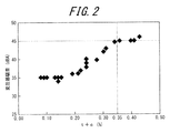
- the transformer noise is less than 45 dB if the sum of the maximum tensile strain t and the maximum compressive strain c in the rolling direction is t + c ⁇ 0.35%.
- t + c> 0.35% strong tensile stress in the rolling direction, strong compressive stress, or both exist, but in this case, as shown in FIG. Since the steel sheet is easily deformed, when it is used as a transformer core, in addition to the deformation of the iron core due to the expansion and contraction of the crystal lattice, a deformation mode that releases internal stress is added during excitation, resulting in high noise. It is considered to be.
- an electron beam As an irradiation condition of a high energy beam, that is, a heat beam, a light beam, or a particle beam, an electron beam will be described below, but the basic concept is the same for other irradiation conditions such as laser irradiation and plasma flame irradiation.
- the grain-oriented electrical steel sheet of the present invention can be produced by irradiating an electron beam in an angle direction of 30 ° or less from the direction perpendicular to the rolling direction so as to cross the rolling direction of the steel sheet.
- the beam scanning from one end to the other end of the steel plate is repeated with an interval of 2 to 10 mm in the rolling direction. If this interval is excessively short, the productivity will be excessively reduced, so that it is preferable to set the distance to 2 mm or more. On the other hand, if it is excessively long, the magnetic domain fragmentation effect is not sufficiently exhibited, so that it is preferable to set it to 10 mm or less.
- irradiation may be performed using a plurality of irradiation sources.
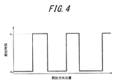
- the irradiation time is often performed along a scanning line so as to repeat a long time (s 1 ) and a short time (s 2 ) as shown in FIG.
- the repeated distance period (hereinafter referred to as dot pitch) is preferably 0.6 mm or less. Normally, s 2 is sufficiently short with respect to s 1 and can be ignored, so the reciprocal of s 1 may be used as the irradiation frequency. If the dot pitch is larger than 0.6 mm, the area irradiated with sufficient energy is reduced, and a sufficient magnetic domain refinement effect cannot be obtained.
- the scanning speed of the irradiated portion on the steel plate is preferably 100 m / s or less.
- the scanning speed is increased, it is necessary to increase the energy irradiated per unit time in order to irradiate energy necessary to subdivide the magnetic domains.
- the scanning speed is 10 m / s or more.
- the beam diameter d ( ⁇ m) needs to satisfy the following equation (2) as the beam profile of the electron beam. 200 ⁇ d ⁇ ⁇ 0.04 ⁇ v 2 + 6.4 ⁇ v + 190 ⁇ (2)
- v (m / s) is the scanning speed of the electron beam on the steel plate surface. If the beam diameter is smaller than 200 ⁇ m, the energy density of the beam becomes excessively high, distortion increases, and hysteresis loss and noise deteriorate.
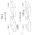
- the beam diameter is excessively large, in the case of dot-shaped irradiation, as schematically shown in FIG. 5, the overlapping area of beam spots irradiated for a long time increases, or continuous beam irradiation occurs.
- the beam irradiation time (rolling direction beam diameter / beam scanning speed) at a point on the beam scanning line becomes excessively long. Therefore, the beam diameter is ( ⁇ 0.04 ⁇ v 2 + 6.4 ⁇ v + 190) ⁇ m or less.
- the detailed mechanism is unknown, but if the irradiation is performed for a long time, the expansion region of the steel sheet expands in the in-plane direction due to thermal diffusion, or after the beam irradiation, the tensile residual strain in the rolling direction also increases. Noise characteristics deteriorate. Therefore, when the beam diameter is large, it is preferable to increase the scanning speed.
- the present inventors investigated the relationship between the beam diameter and (t + c). As shown in FIG. 6, when the beam diameter is ( ⁇ 0.04 ⁇ v 2 + 6.4 ⁇ v + 190) ⁇ m or less, It was found that (t + c) after irradiation can be suppressed. Therefore, in the present invention, the surface scanning speed v (m / s) and the beam diameter d ( ⁇ m) are expressed by the following equation (2). 200 ⁇ d ⁇ ⁇ 0.04 ⁇ v 2 + 6.4 ⁇ v + 190 ⁇ (2) It was decided to satisfy this relationship.
- the electron beam profile was measured by a known slit method.
- the slit width was adjusted to 30 ⁇ m, and the half width of the obtained beam profile was taken as the beam diameter.
- other irradiation energy and the like have been adjusted as appropriate based on conventional knowledge because the adjustment range and appropriate values differ depending on conditions such as WD (Working Distance) and vacuum degree.
- the beam diameter was the half width of the beam profile obtained by the knife edge method.
- the outer shape of the model transformer transformer is a steel plate having a 500 mm square and a width of 100 mm.
- the steel sheet is bevel-cut into the shape shown in FIG. 7, and the stacking thickness is about 15 mm and the iron core weight is about 20 kg, so that the steel sheet having a thickness of 0.23 mm is 70 sheets, the steel sheet having a thickness of 0.27 mm is 60 sheets, 80 sheets of 0.20 mm thick steel plates are laminated.
- the longitudinal direction of the sample subjected to oblique shearing was set to be the rolling direction.
- the laminating method was two-layered 5-step step lap stacking. Specifically, as the central leg member (shape B), one type of symmetrical member (B-1) and two types of asymmetrical members (B-2, B-3) (in reality, three types) Using asymmetric members (five kinds by turning over B-2 and B-3), the actual stacking method is, for example, “B-3” “B-2” “B-1” “B-2 inversion” “B -3 inversion ".
- the iron cores were stacked on a flat surface, and sandwiched with a bakelite holding plate with a load of about 0.1 MPa and fixed. The three phases were excited by shifting the phase by 120 °, and the iron loss and noise were measured at a magnetic flux density of 1.7 T. Noise was measured with a microphone at a position (2 places) 20 cm away from the iron core surface and expressed in dBA units with A scale correction.
- Component composition of the material examples include the following elements.
- Si 2.0 to 8.0 mass%
- Si is an element effective for increasing the electrical resistance of steel and improving iron loss.
- the content is less than 2.0% by mass, a sufficient iron loss reducing effect cannot be achieved. If it exceeds 0% by mass, the workability is remarkably reduced and the magnetic flux density is also reduced. Therefore, the Si content is preferably in the range of 2.0 to 8.0% by mass.
- C 50 mass ppm or less C is added to improve the hot-rolled sheet structure, but it is preferable to reduce C to 50 mass ppm or less where magnetic aging does not occur in the final product.
- Mn 0.005 to 1.0 mass% Mn is an element necessary for improving the hot workability, but if the content is less than 0.005% by mass, the effect of addition is poor, whereas if it exceeds 1.0% by mass, the magnetic flux density of the product plate Therefore, the amount of Mn is preferably in the range of 0.005 to 1.0% by mass.
- Ni 0.03-1.50% by mass
- Sn 0.01-1.50% by mass
- Sb 0.005-1.50% by mass
- Cu 0.03-3.0% by mass
- P At least one selected from 0.03 to 0.50 mass%
- Mo 0.005 to 0.10 mass%
- Cr 0.03 to 1.50 mass%
- Ni improves the hot rolled sheet structure
- the content is less than 0.03% by mass
- the effect of improving the magnetic properties is small.
- it exceeds 1.50% by mass the secondary recrystallization becomes unstable and the magnetic properties deteriorate.
- the Ni content is preferably in the range of 0.03 to 1.50 mass%.
- Sn, Sb, Cu, P, Mo, and Cr are elements that are useful for improving the magnetic properties, but if any of them does not satisfy the lower limit of each component, the effect of improving the magnetic properties is small. If the upper limit amount of each component is exceeded, the development of secondary recrystallized grains is hindered. The balance other than the above components is inevitable impurities and Fe mixed in the manufacturing process.
- Electron beam, sample laser irradiation in this embodiment, SST rolling direction B 8 were measured in (veneer magnetic tester) is 1.95T from 1.91 T, iron loss was measured in the model transformer W 17 / 50 is 1.01 to 1.03 W / kg, and is a grain-oriented electrical steel sheet with a coating.
- a steel sheet with a coating has a two-layer coating on the surface of the ground iron: a glassy coating composed mainly of Mg 2 SiO 4 and a coating (phosphate coating) on which an inorganic treatment solution is baked. It has a structure to do.
- the electron beam and laser irradiation scanning was performed in a direction perpendicular to the rolling direction of the steel sheet, linearly across the entire width across the steel sheet, and at a periodic interval of 5 mm in the rolling direction.
- laser irradiation was performed using a continuous wave fiber laser device, and the laser wavelength was near infrared light of about 1 ⁇ m.
- the beam diameter in the rolling direction and the direction perpendicular to the rolling direction are the same.
- the electron beam irradiation was performed at an acceleration voltage of 60 kV, a dot pitch of 0.01 to 0.40 mm, a shortest distance from the center of the focusing coil to the irradiated material: 700 mm, and a processing chamber pressure of 0.5 Pa or less.
- the strain distribution in the cross section in the rolling direction is shown in CrossCourt Ver. It was measured by the EBSD-wilkinson method using 3.0 (manufactured by BLG Products Bristol).
- the measurement visual field was in the range of (rolling direction 600 ⁇ m or more ⁇ total thickness), and the center of the laser and electron beam irradiation was placed at the approximate center of the measurement visual field.
- the measurement pitch was 5 ⁇ m, and the position within the same grain that was 50 ⁇ m away from the corner of the measurement field was selected as the undistorted reference point. The obtained results are shown in Table 1.
Landscapes
- Chemical & Material Sciences (AREA)
- Engineering & Computer Science (AREA)
- Mechanical Engineering (AREA)
- Organic Chemistry (AREA)
- Metallurgy (AREA)
- Materials Engineering (AREA)
- Physics & Mathematics (AREA)
- Crystallography & Structural Chemistry (AREA)
- Thermal Sciences (AREA)
- Electromagnetism (AREA)
- Manufacturing & Machinery (AREA)
- Dispersion Chemistry (AREA)
- Power Engineering (AREA)
- Manufacturing Of Steel Electrode Plates (AREA)
- Soft Magnetic Materials (AREA)
Priority Applications (4)
| Application Number | Priority Date | Filing Date | Title |
|---|---|---|---|
| CN201280064393.1A CN104093870B (zh) | 2011-12-28 | 2012-12-28 | 方向性电磁钢板及其制造方法 |
| US14/368,812 US9984800B2 (en) | 2011-12-28 | 2012-12-28 | Grain-oriented electrical steel sheet and method of manufacturing same |
| KR1020147017560A KR101553497B1 (ko) | 2011-12-28 | 2012-12-28 | 방향성 전자 강판 및 그 제조 방법 |
| EP12864000.0A EP2799580B1 (fr) | 2011-12-28 | 2012-12-28 | Plaque d'acier électromagnétique orientée et son procédé de fabrication |
Applications Claiming Priority (2)
| Application Number | Priority Date | Filing Date | Title |
|---|---|---|---|
| JP2011-289783 | 2011-12-28 | ||
| JP2011289783A JP5884165B2 (ja) | 2011-12-28 | 2011-12-28 | 方向性電磁鋼板およびその製造方法 |
Publications (2)
| Publication Number | Publication Date |
|---|---|
| WO2013100200A1 true WO2013100200A1 (fr) | 2013-07-04 |
| WO2013100200A8 WO2013100200A8 (fr) | 2014-06-12 |
Family
ID=48697660
Family Applications (1)
| Application Number | Title | Priority Date | Filing Date |
|---|---|---|---|
| PCT/JP2012/084307 Ceased WO2013100200A1 (fr) | 2011-12-28 | 2012-12-28 | Plaque d'acier électromagnétique orientée et son procédé de fabrication |
Country Status (5)
| Country | Link |
|---|---|
| US (1) | US9984800B2 (fr) |
| EP (1) | EP2799580B1 (fr) |
| JP (1) | JP5884165B2 (fr) |
| KR (1) | KR101553497B1 (fr) |
| WO (1) | WO2013100200A1 (fr) |
Cited By (3)
| Publication number | Priority date | Publication date | Assignee | Title |
|---|---|---|---|---|
| WO2015129255A1 (fr) * | 2014-02-28 | 2015-09-03 | Jfeスチール株式会社 | Tôle d'acier électromagnétique à orientation pour transformateur à faible bruit et procédé de fabrication de ladite tôle |
| WO2015129253A1 (fr) * | 2014-02-28 | 2015-09-03 | Jfeスチール株式会社 | Feuille d'acier électromagnétique orientée pour un transformateur à faible bruit, et procédé de fabrication de ladite feuille |
| EP3211104A4 (fr) * | 2014-10-23 | 2017-11-15 | JFE Steel Corporation | Tôle d'acier électromagnétique à grains orientés et son procédé de production |
Families Citing this family (15)
| Publication number | Priority date | Publication date | Assignee | Title |
|---|---|---|---|---|
| KR101562962B1 (ko) * | 2014-08-28 | 2015-10-23 | 주식회사 포스코 | 방향성 전기강판의 자구미세화 방법과 자구미세화 장치 및 이로부터 제조되는 방향성 전기강판 |
| CN107406935B (zh) | 2015-04-20 | 2019-03-12 | 新日铁住金株式会社 | 方向性电磁钢板 |
| CN110352255B (zh) | 2017-02-28 | 2021-09-21 | 杰富意钢铁株式会社 | 方向性电磁钢板及其制造方法 |
| CN108660295A (zh) * | 2017-03-27 | 2018-10-16 | 宝山钢铁股份有限公司 | 一种低铁损取向硅钢及其制造方法 |
| RU2744690C1 (ru) | 2018-03-30 | 2021-03-15 | ДжФЕ СТИЛ КОРПОРЕЙШН | Железный сердечник трансформатора |
| KR102162984B1 (ko) * | 2018-12-19 | 2020-10-07 | 주식회사 포스코 | 방향성 전기강판 및 그의 제조 방법 |
| MX2021015737A (es) * | 2019-06-17 | 2022-01-27 | Jfe Steel Corp | Lamina de acero electrico de grano orientado y metodo para producir la misma. |
| CA3157424C (fr) * | 2019-12-25 | 2024-05-28 | Jfe Steel Corporation | Tole d'acier electromagnetique a grains orientes et procede de fabrication a cet effet |
| WO2022013960A1 (fr) * | 2020-07-15 | 2022-01-20 | 日本製鉄株式会社 | Feuille d'acier électromagnétique à grains orientés, et procédé de fabrication d'une feuille d'acier électromagnétique à grains orientés |
| MX2023006262A (es) * | 2020-11-27 | 2023-06-12 | Jfe Steel Corp | Lamina de acero electrico de grano orientado y metodo de produccion de la misma. |
| JP7610157B2 (ja) * | 2021-03-26 | 2025-01-08 | 日本製鉄株式会社 | 方向性電磁鋼板及びその製造方法 |
| JP7459956B2 (ja) * | 2021-05-31 | 2024-04-02 | Jfeスチール株式会社 | 方向性電磁鋼板 |
| EP4332247A4 (fr) * | 2021-05-31 | 2024-10-09 | JFE Steel Corporation | Tôle d'acier électrique à grains orientés |
| JPWO2024225454A1 (fr) | 2023-04-27 | 2024-10-31 | ||
| EP4707420A1 (fr) * | 2023-04-27 | 2026-03-11 | Nippon Steel Corporation | Tôle d'acier électromagnétique à grains orientés et procédé de commande de domaine magnétique |
Citations (10)
| Publication number | Priority date | Publication date | Assignee | Title |
|---|---|---|---|---|
| JPS59229419A (ja) * | 1983-06-11 | 1984-12-22 | Nippon Steel Corp | 方向性電磁鋼板の鉄損特性改善方法 |
| JPS6151803A (ja) * | 1984-08-21 | 1986-03-14 | Kawasaki Steel Corp | 鉄損の低い一方向性けい素鋼板 |
| JPH028027B2 (fr) | 1983-10-27 | 1990-02-22 | Kawasaki Steel Co | |
| JPH0313293B2 (fr) | 1981-07-24 | 1991-02-22 | Nippon Steel Corp | |
| JPH05335128A (ja) * | 1992-05-29 | 1993-12-17 | Kawasaki Steel Corp | 騒音特性の優れた低鉄損一方向性珪素鋼板の製造方法 |
| JPH0765106B2 (ja) | 1988-10-26 | 1995-07-12 | 川崎製鉄株式会社 | 低鉄損一方向性けい素鋼板の製造方法 |
| JP3500103B2 (ja) | 1999-12-24 | 2004-02-23 | 新日本製鐵株式会社 | トランス用一方向性電磁鋼板 |
| JP2008106288A (ja) | 2006-10-23 | 2008-05-08 | Nippon Steel Corp | 鉄損特性の優れた一方向性電磁鋼板 |
| JP4123679B2 (ja) | 2000-04-25 | 2008-07-23 | Jfeスチール株式会社 | 方向性電磁鋼板の製造方法 |
| JP4344264B2 (ja) | 2004-03-08 | 2009-10-14 | 新日本製鐵株式会社 | 低鉄損一方向性電磁鋼板 |
Family Cites Families (6)
| Publication number | Priority date | Publication date | Assignee | Title |
|---|---|---|---|---|
| JP2694941B2 (ja) * | 1985-05-02 | 1997-12-24 | 新日本製鐵株式会社 | 低鉄損一方向性電磁鋼板の製造方法 |
| US5296051A (en) * | 1993-02-11 | 1994-03-22 | Kawasaki Steel Corporation | Method of producing low iron loss grain-oriented silicon steel sheet having low-noise and superior shape characteristics |
| KR100259990B1 (ko) | 1993-12-28 | 2000-06-15 | 에모또 간지 | 철손이 적은 일방향성 전자강판 및 제조방법 |
| JPH07320922A (ja) | 1994-03-31 | 1995-12-08 | Kawasaki Steel Corp | 鉄損の低い一方向性電磁鋼板 |
| JP2006254645A (ja) | 2005-03-14 | 2006-09-21 | Nippon Steel Corp | インナー螺旋回転機鉄心の製造方法 |
| RU2570250C1 (ru) * | 2011-12-27 | 2015-12-10 | ДжФЕ СТИЛ КОРПОРЕЙШН | Текстурированный лист из электротехнической стали |
-
2011
- 2011-12-28 JP JP2011289783A patent/JP5884165B2/ja active Active
-
2012
- 2012-12-28 EP EP12864000.0A patent/EP2799580B1/fr active Active
- 2012-12-28 US US14/368,812 patent/US9984800B2/en active Active
- 2012-12-28 KR KR1020147017560A patent/KR101553497B1/ko active Active
- 2012-12-28 WO PCT/JP2012/084307 patent/WO2013100200A1/fr not_active Ceased
Patent Citations (10)
| Publication number | Priority date | Publication date | Assignee | Title |
|---|---|---|---|---|
| JPH0313293B2 (fr) | 1981-07-24 | 1991-02-22 | Nippon Steel Corp | |
| JPS59229419A (ja) * | 1983-06-11 | 1984-12-22 | Nippon Steel Corp | 方向性電磁鋼板の鉄損特性改善方法 |
| JPH028027B2 (fr) | 1983-10-27 | 1990-02-22 | Kawasaki Steel Co | |
| JPS6151803A (ja) * | 1984-08-21 | 1986-03-14 | Kawasaki Steel Corp | 鉄損の低い一方向性けい素鋼板 |
| JPH0765106B2 (ja) | 1988-10-26 | 1995-07-12 | 川崎製鉄株式会社 | 低鉄損一方向性けい素鋼板の製造方法 |
| JPH05335128A (ja) * | 1992-05-29 | 1993-12-17 | Kawasaki Steel Corp | 騒音特性の優れた低鉄損一方向性珪素鋼板の製造方法 |
| JP3500103B2 (ja) | 1999-12-24 | 2004-02-23 | 新日本製鐵株式会社 | トランス用一方向性電磁鋼板 |
| JP4123679B2 (ja) | 2000-04-25 | 2008-07-23 | Jfeスチール株式会社 | 方向性電磁鋼板の製造方法 |
| JP4344264B2 (ja) | 2004-03-08 | 2009-10-14 | 新日本製鐵株式会社 | 低鉄損一方向性電磁鋼板 |
| JP2008106288A (ja) | 2006-10-23 | 2008-05-08 | Nippon Steel Corp | 鉄損特性の優れた一方向性電磁鋼板 |
Non-Patent Citations (3)
| Title |
|---|
| "Recent progress in soft magnetic steels", 155TH/156TH NISHIYAMA MEMORIAL TECHNICAL SEMINAR, THE IRON AND STEEL INSTITUTE OF JAPAN, 10 February 1995 (1995-02-10) |
| "Recent progress in soft magnetic steels, 55th/156th Nishiyama Memorial Technical Seminar", 10 February 1995, THE IRON AND STEEL INSTITUTE OF JAPAN |
| See also references of EP2799580A4 |
Cited By (9)
| Publication number | Priority date | Publication date | Assignee | Title |
|---|---|---|---|---|
| WO2015129255A1 (fr) * | 2014-02-28 | 2015-09-03 | Jfeスチール株式会社 | Tôle d'acier électromagnétique à orientation pour transformateur à faible bruit et procédé de fabrication de ladite tôle |
| WO2015129253A1 (fr) * | 2014-02-28 | 2015-09-03 | Jfeスチール株式会社 | Feuille d'acier électromagnétique orientée pour un transformateur à faible bruit, et procédé de fabrication de ladite feuille |
| JP2015161017A (ja) * | 2014-02-28 | 2015-09-07 | Jfeスチール株式会社 | 低騒音変圧器用の方向性電磁鋼板およびその製造方法 |
| JP2015161024A (ja) * | 2014-02-28 | 2015-09-07 | Jfeスチール株式会社 | 低騒音変圧器用の方向性電磁鋼板およびその製造方法 |
| CN106029917A (zh) * | 2014-02-28 | 2016-10-12 | 杰富意钢铁株式会社 | 低噪声变压器用取向性电磁钢板及其制造方法 |
| US20170016085A1 (en) * | 2014-02-28 | 2017-01-19 | Jfe Steel Corporation | Grain-oriented electrical steel sheet for low-noise transformer, and method of manufacturing said sheet |
| EP3112480A4 (fr) * | 2014-02-28 | 2017-03-29 | JFE Steel Corporation | Tôle d'acier électromagnétique à orientation pour transformateur à faible bruit et procédé de fabrication de ladite tôle |
| EP3211104A4 (fr) * | 2014-10-23 | 2017-11-15 | JFE Steel Corporation | Tôle d'acier électromagnétique à grains orientés et son procédé de production |
| US11225698B2 (en) | 2014-10-23 | 2022-01-18 | Jfe Steel Corporation | Grain-oriented electrical steel sheet and process for producing same |
Also Published As
| Publication number | Publication date |
|---|---|
| US20140338792A1 (en) | 2014-11-20 |
| JP2013139590A (ja) | 2013-07-18 |
| KR20140103995A (ko) | 2014-08-27 |
| JP5884165B2 (ja) | 2016-03-15 |
| EP2799580A4 (fr) | 2015-06-03 |
| EP2799580A1 (fr) | 2014-11-05 |
| CN104093870A (zh) | 2014-10-08 |
| EP2799580B1 (fr) | 2018-10-10 |
| KR101553497B1 (ko) | 2015-09-15 |
| US9984800B2 (en) | 2018-05-29 |
| WO2013100200A8 (fr) | 2014-06-12 |
Similar Documents
| Publication | Publication Date | Title |
|---|---|---|
| JP5884165B2 (ja) | 方向性電磁鋼板およびその製造方法 | |
| CN103069033B (zh) | 方向性电磁钢板及其制造方法 | |
| CN103025903B (zh) | 方向性电磁钢板及其制造方法 | |
| JP5668379B2 (ja) | 方向性電磁鋼板およびその製造方法 | |
| CN103069036B (zh) | 方向性电磁钢板 | |
| CN104105808B (zh) | 取向性电磁钢板 | |
| JP5668795B2 (ja) | 方向性電磁鋼板およびそれを用いた変圧器鉄心 | |
| JP5983306B2 (ja) | 鉄損に優れた変圧器鉄心の製造方法 | |
| JP2012057232A (ja) | 方向性電磁鋼板およびその製造方法 | |
| JP5565307B2 (ja) | 方向性電磁鋼板の製造方法 | |
| JP2023121125A (ja) | 方向性電磁鋼板 | |
| JP7459955B2 (ja) | 方向性電磁鋼板 | |
| JP7568176B1 (ja) | 方向性電磁鋼板および積層鉄心 | |
| CN104093870B (zh) | 方向性电磁钢板及其制造方法 | |
| JP5691886B2 (ja) | 方向性電磁鋼板および方向性電磁鋼板の絶縁被膜形成方法 | |
| WO2025022804A1 (fr) | Noyau de fer pour transformateur et transformateur | |
| WO2023007953A1 (fr) | Noyau enroulé et procédé de fabrication de noyau enroulé |
Legal Events
| Date | Code | Title | Description |
|---|---|---|---|
| 121 | Ep: the epo has been informed by wipo that ep was designated in this application |
Ref document number: 12864000 Country of ref document: EP Kind code of ref document: A1 |
|
| WWE | Wipo information: entry into national phase |
Ref document number: 2012864000 Country of ref document: EP |
|
| ENP | Entry into the national phase |
Ref document number: 20147017560 Country of ref document: KR Kind code of ref document: A |
|
| WWE | Wipo information: entry into national phase |
Ref document number: 14368812 Country of ref document: US |
|
| NENP | Non-entry into the national phase |
Ref country code: DE |
|
| ENP | Entry into the national phase |
Ref document number: 2014131084 Country of ref document: RU Kind code of ref document: A |