WO2013100436A1 - 포장 결속용 망원단 - Google Patents
포장 결속용 망원단 Download PDFInfo
- Publication number
- WO2013100436A1 WO2013100436A1 PCT/KR2012/010695 KR2012010695W WO2013100436A1 WO 2013100436 A1 WO2013100436 A1 WO 2013100436A1 KR 2012010695 W KR2012010695 W KR 2012010695W WO 2013100436 A1 WO2013100436 A1 WO 2013100436A1
- Authority
- WO
- WIPO (PCT)
- Prior art keywords
- yarn
- denier
- thickness
- tensile strength
- ring
- Prior art date
- Legal status (The legal status is an assumption and is not a legal conclusion. Google has not performed a legal analysis and makes no representation as to the accuracy of the status listed.)
- Ceased
Links
Images

Classifications
-
- D—TEXTILES; PAPER
- D04—BRAIDING; LACE-MAKING; KNITTING; TRIMMINGS; NON-WOVEN FABRICS
- D04B—KNITTING
- D04B21/00—Warp knitting processes for the production of fabrics or articles not dependent on the use of particular machines; Fabrics or articles defined by such processes
- D04B21/10—Open-work fabrics
- D04B21/12—Open-work fabrics characterised by thread material
-
- D—TEXTILES; PAPER
- D10—INDEXING SCHEME ASSOCIATED WITH SUBLASSES OF SECTION D, RELATING TO TEXTILES
- D10B—INDEXING SCHEME ASSOCIATED WITH SUBLASSES OF SECTION D, RELATING TO TEXTILES
- D10B2505/00—Industrial
- D10B2505/10—Packaging, e.g. bags
Definitions
- the present invention relates to a telescopic binding fabric for packaging, and more particularly, to a packaging binding telescopic fabric having improved tensile strength relative to the weight of the yarn due to the improved slope structure.
- the pavement binding telephoto fabric is arranged by arranging the warp at a predetermined interval, and is formed by weaving the connecting yarn in a zigzag pattern between each warp.
- Wrapping telescopic fabric is easily used to wrap an object in place of a rope, and in particular, in recent years it is widely used for tying the weeds unit by unit in the pre-stage of the wrapping lapping silo.
- warp yarns having a thickness of 350 to 450 denier one set as polyethylene film yarns are disposed at intervals of 1 inch, and between the warp yarns to 350 to 450 denier
- a telescopic cloth for wrapping lapping silos formed by weaving connecting yarns having a thickness of 1 set in a zigzag pattern.
- the telescopic yarn in order to form the yarn into the yarn, the telescopic yarn must be woven in a ring shape by bending the yarn, so that the yarn has 30 to 40% lower tensile strength than the straight form before the yarn is bent.
- the interval between the inclination is tightly woven, but it takes a lot of time to weave, while the inclined to receive a lot of external force is not easy to break and there is a risk that the telephoto will burst, which is a disadvantage that does not smoothly work to tighten the four weeds have.
- the cloth for wrapping lapping silo disclosed in Korean Patent No. 1019465 is composed of a double-polyethylene monofilament yarn having a thickness of 350 to 450 deniers as a warp 4, and a warp 4 Each of them is used as a polyethylene yarn as a single-ply connecting yarn 6 of 350 to 450 denier thicknesses, and the arrangement interval between the warp yarns 4 is formed to be 2 inches.
- the telephoto end 2 is twice as thick as the inclined yarn 4 and the polyethylene monofilament yarn having a higher tensile strength than the polyethylene film yarn is used. Compared to the weight of the tough, the production yield is very high.
- the inclined yarn is also formed of three strands of inclined yarns, the loss of tensile strength occurs in the process of forming the yarn, and the tensile strength does not come out with respect to the weight of the yarn. Due to the high manufacturing cost is not economical disadvantages.
- an object of the present invention is to provide a very high packaging strength telescopic fabric in terms of price competitiveness due to the low tensile strength compared to the weight of the yarn, as well as low manufacturing cost.
- the present invention in the mesh for packaging binding formed in a mesh shape by zigzag weaving the connecting yarn between every inclination, three-stranded loop having a thickness of 150 ⁇ 400 denier 1 set (t1) Between the yarns, it is composed of slopes by arranging 400 ⁇ 1000 denier single-thickness (t2) straight yarns, and multiplying the total thickness of the ring yarns (3t1) by 0.6 times and the value of the straight pole yarn thickness (t2) The combined value is characterized in that formed from 900 to 1500 denier.
- the yarn having a large loss of tensile strength is formed to a minimum thickness, and a straight column yarn without loss of tensile strength is disposed between the yarns to be inclined so that the tensile strength is very high compared to the weight of the yarn. Since the weight can be reduced, manufacturing cost is low and it is very excellent in price competitiveness.
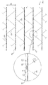
- FIG. 1 is a perspective view of a telescopic binding telescopic fabric according to a first embodiment of the present invention
- FIG. 2 is a plan view of the telescopic binding fabric of FIG. 1.
- the present invention is formed with a minimum thickness so that the ring yarn with a large loss of tensile strength at the slope of the telephoto end is formed to a minimum thickness, and a straight column yarn formed thicker than the ring yarn between the ring yarn to reinforce the inclined tensile strength By placing the maximal tensile strength to weight of the yarn.
- FIG. 1 is a perspective view of a packaging binding telephoto fabric according to a first embodiment of the present invention
- Figure 2 is a plan view of the packaging binding telephoto fabric of FIG.
- the warp yarn 4 and the connecting yarn 6 may be formed of both polyethylene yarn, nylon yarn, polypropylene yarn, and the like, but polyethylene yarn is most preferred.
- polyethylene monofilament yarns have a higher draw ratio than polyethylene film yarns, so the draw ratio is proportional to the crystallinity and density, and the density is proportional to the tensile strength.
- polyethylene monofilament yarns have a much higher tensile strength than polyethylene film yarns.
- polyethylene monofilament yarns have 30-40% better tensile strength than polyethylene film yarns, while the price is 30-40% cheaper.
- the ring yarn 8 and the connecting yarn 6 forming the shape of the packaging binding telephoto fabric 2 are composed of polyethylene monofilament yarn, and the straight columnar yarn 10 is the ring yarn 8. Alternately, it may be arranged with polyethylene film yarns having different colors to form the aesthetics of the packaging fabric telephoto fabric 2.
- the inclined 4 of the telescopic end 2 for pavement binding is comprised so that the straight columnar yarn 10 may be arrange
- Ring yarn (8) is composed of three strands are tangled with each other to form a ring-shaped nose (k), between the nose (k) of the ring yarn 8 so that the straight columnar yarn 10 passes through. Is placed.
- the ring yarn 8 is woven through a process in which the machine rotates at a high speed of 800 ⁇ 1200rpm to produce more than 1000 rings per minute, and the ring yarn 8 is mostly of the frictional heat and twisting and bending during this weaving process Repeated loss of inherent tensile strength, the woven form is also very unstable as a series of twisting knots between the yarns in the form of rings.
- the loss of tensile strength of the ring yarn 8 is about 30 to 40%, and in the embodiment of the present invention, it is assumed that the loss of tensile strength of the ring yarn 8 is 40%. do.
- the ring yarn 8 having a large loss of tensile strength is formed to have a minimum thickness of 150-400 denier 1-ply thickness t1 so as to maintain only a shape in the telescopic fabric 2 for packaging binding.
- the straight columnar yarn 10 without loss of tensile strength may be formed to have a thickness of 400 to 1000 denier one-ply t2 thicker than the ring yarn 8.
- the numerical value of the ring yarn 8 and the straight columnar yarn 10 is used to maximize the tensile strength to weight while maintaining the minimum shape of the ring yarn (8) in the telescopic end for packaging binding (2) It is the numerical value obtained by the applicant through several experiments.
- the thickness t1 of the ring yarn 8 is not within the lower limit within the numerical range described above, the shape of the ring yarn 8 may not be properly maintained in the telescopic end for packaging binding 2, and the thickness of the ring yarn 8 may be reduced. If (t1) exceeds the upper limit, the weight of the yarn becomes too heavy and the tensile strength to weight may drop.
- the thickness t2 of the straight columnar yarn 10 does not fall below the lower limit within the numerical range, the thickness t1 of the ring yarn 8 becomes thicker, so that the tensile strength to weight falls, and the straight columnar yarn ( If the thickness t2 of 10) exceeds the upper limit, the thickness t1 of the ring yarn 8 may be relatively thin, and thus the shape may not be properly maintained.
- the weight of the yarn is proportional to the sum of the thicknesses of the threads, and the total weight of the warp yarn 4 is based on the fact that 1 denier has a weight of 9000 m and the weight of the thread is 1 g. Can be calculated as
- the thickness of the warp yarn 4 is calculated based on the annular yarn 8 (150 to 400 denier 1-ply thickness t1) and the straight columnar yarn (10) 400 to 1000 denier 1-ply (t2). It can be seen that 3t1 + t2) is 850-2200 denier.
- the telephoto fabric disclosed in Patent No. 1019465 is a very small number, considering that the total thickness of the inclination is 350 to 450 deniers, and the sum of the inclinations is 2100 to 2700, which is '(350 to 450) ⁇ 2 ⁇ 3'. It can be seen that the weight of the yarn is also much less than that of the telephoto fabric disclosed in patent 1019465.
- the tensile strength of the warp yarn 4 combined with the ring yarn 8 and the straight columnar yarn 10 is a value considering the loss of 40%, which is the tensile strength of the ring yarn 8, It can be represented by the tensile strength of the yarn having a value of the sum of the thickness (t1) ⁇ 3 ⁇ 0.6 'and the' thickness (t2) of the straight columnar yarn 10, which is the tensile strength of the straight columnar yarn 10.
- the tensile strength of the warp yarn 4 can be expressed as the tensile strength of the yarn having the thickness t1 of the ring yarn 8 x 3 x 0.6 + the thickness t2 of the straight columnar yarn 10.
- the ring yarn 8 is a sum of 2, it is multiplied by 2.
- the numerical value was calculated based on the tensile strength from the network disclosed in Patent No. 1019465. .
- Patent No. 1019465 uses a polyethylene monofilament yarn having a slope of 350-450 denier two-ply thick, which is inclined tensile strength compared to a telephoto fabric formed of 350-450 denier one-ply polyethylene film yarn widely used in the art. Is more than twice as high.
- the telephoto fabric disclosed in Patent No. 1019465 uses a yarn with a slope of 350 to 450 denier two-ply thick, the tensile strength of the yarn is 350 ⁇ 0.6 ⁇ 2 ⁇ 3 to 450 ⁇ 0.6 ⁇ 2 in consideration of the loss of 40%.
- X3 that is, 1260 to 1620 deniers.
- the user can use the ring yarn 8 and the straight type as long as the thickness (t1) of the ring thread 8 (t1) x 3 x 0.6 + the thickness t2 of the straight column 10 is maintained between 900 and 1500 denier.
- the thickness t1 (t2) of the pillar yarn 10 can be adjusted.
- the ring yarn 8 and the straight columnar yarn 10 configured as described above may be a problem when they are arranged together at the same inclination 4 because of mutual different elongation. While the telephoto end 2 is heat-treated through a heat treatment apparatus, the ring yarn 8 and the straight columnar yarn 10 of the warp yarn 4 may be formed to have similar elongations.
- the connecting yarn 6 of the packing binding telephoto 2 may be formed to be zigzag every two nose (k) of the inclination (4).
- the connecting yarn 6 has a weaker force than the warp yarn 4, so the thickness t3 of the connecting yarn 6 is smaller than that of the warp yarn 4. It can be formed from 150 to 300 denier.
- the arrangement interval d between the warp yarns 4 is a conventional polyethylene film yarn, instead of increasing the tensile strength by arranging the straight columnar yarn 10 between the ring yarns 8 with the warp yarn 4 which receives a lot of force. It is formed to be 1 to 2 times wider than the interval between the inclinations of the woven telephoto end, and it can be preferably 1 to 2 inches.
- the packaging binding telephoto fabric 2 may be woven into various standard sizes, such as width 1m, 1.25m, 1.30m, 1.60m, depending on the size of the wrapping lapping silo.
- both telephoto fabrics 2 have a width of 1.25 m and a length of 3000 m, and 34 inclinations 4 and 33 connecting yarns 6 per width.
- the thickness t3 of the connecting yarn 6 is 300 denier one sum in common.
- the tensile strength of the ring yarn 8 is 250. Since the denier yarn is three strands, it is multiplied by 3 and considering the 40% loss, it becomes 250 x 3 x 0.6 denier, and the tensile strength of the straight column 10 is 800 denier because there is no loss.
- the ring yarn 8 according to the embodiment of the present invention is 2.83 kg since 250 denier ⁇ 3000 ⁇ 9000m ⁇ 34 pieces, and the straight columnar yarn 10 has 800 denier ⁇ 3000 ⁇ 9000m ⁇ 34 pieces, so it is 9.07 kg. Since the connecting yarn 6 is 300 denier x 3000 9000 m x 33 pieces, it becomes 3.3 kg.
- the telephoto fabric disclosed in Patent No. 1019465 is formed of only yarns having a warp yarn, and uses a yarn of 350 denier doubles, which is the lowest value within the range of 350 to 450 denier described in claim 1.
- the inclination is 23.8 kg because it is 350 ⁇ 6 ⁇ 3000 ⁇ 9000 m ⁇ 34, and the connecting yarn is 3.3 kg because it is 300 denier ⁇ 3000 ⁇ 9000 m ⁇ 33.
- the telephoto fabric 2 according to the embodiment of the present invention can consume 16.72 kg of yarn to maintain the tensile strength of the yarn having 1250 denier, while the ring disclosed in Patent No. 1019465 It can be seen that the telephoto fabric that forms the slope only consumes 29.81 kg of yarn and maintains the tensile strength of the yarn having 1260 denier.
- the packaging binding network 2 can produce a similar tensile strength with about half the weight of the yarn compared to the telephoto fabric formed inclined only by the ring yarn disclosed in Patent No. 1019465. You can check it.
- the packaging binding telephoto fabric 2 according to the embodiment of the present invention not only has a very high tensile strength relative to the weight of the yarn, but also minimizes the weight of the yarn so that the manufacturing cost is low and the price is competitive. The effect is very good at.
Landscapes
- Engineering & Computer Science (AREA)
- Textile Engineering (AREA)
- Woven Fabrics (AREA)
- Knitting Of Fabric (AREA)
- Braiding, Manufacturing Of Bobbin-Net Or Lace, And Manufacturing Of Nets By Knotting (AREA)
- Packages (AREA)
- Package Frames And Binding Bands (AREA)
Description
본 발명은 포장 결속용 망원단에 관한 것으로서, 특히, 경사의 구조가 개선되어 실의 중량 대비 인장강도가 높아진 포장 결속용 망원단에 관한 것이다.
일반적으로 포장 결속용 망원단은 경사들을 일정 간격으로 배치하고, 경사들 사이마다 연결사를 지그재그로 엮어서 그물코 모양으로 형성하여서 구성된다.
포장 결속용 망원단은 로프를 대신하여 물건을 포장하는데 용이하게 사용되며, 특히, 최근에는 곤포 랩핑 사일로의 전단계에서 사초들을 단위별로 묶는 용도로 많이 사용된다.
곤포 랩핑 사일로의 전단계에 사용되는 종래의 망원단의 일 예로, 폴리에틸렌 필름사로서 350∼450데니어 1합의 굵기를 가진 경사들을 1인치 간격으로 배치하고, 경사들 사이마다 폴리에틸렌 필름사로서 350∼450데니어 1합의 굵기를 가진 연결사를 지그재그로 엮어서 그물코 모양으로 형성된 곤포 랩핑 사일로용 망원단이 있다.
이러한 망원단은 대부분 사초들을 감싸서 일정단위로 묶을때 연결사에 비하여 경사가 힘을 더 많이 받게 되므로, 연결사는 1가닥의 실로 형성되는데 반하여 경사는 3가닥의 실이 꺽여서 엮어진 고리사로 형성된다.
그러나, 상기 망원단은 실을 고리사로 형성하기 위해서는 실을 꺽어서 고리형태로 엮어야 하므로, 고리사는 꺽기 전 스트레이트 형태에 비하여 인장강도가 30∼40% 정도 떨어지게 된다.
또한, 경사들의 간격이 촘촘하게 짜여져 제직하는데 시간이 많이 소요되는데 비하여, 외력을 많이 받는 경사가 질기지 못하여 쉽게 끊어져 망원단이 터질 우려가 있고, 이로 인해 사초들을 여미는 작업을 원활하게 수행하지 못하는 단점이 있다.
상기의 문제점을 해결하기 위하여 국내 특허 제1019465호에 개시된 곤포 랩핑 사일로용 망원단(2)은, 350∼450데니어 굵기의 2합 폴리에틸렌 모노필라멘트사를 경사(4)로 구성하고, 경사(4)들 사이마다 폴리에틸렌사로서 350∼450데니어 굵기의 1합 연결사(6)로 사용하고, 경사(4)간의 배치 간격을 2인치로 형성하여서 구성된다.
상기의 망원단(2)은 힘을 많이 받는 경사(4)를 2배로 굵게 하고 인장강도가 폴리에틸렌 필름사보다 높은 폴리에틸렌 모노필라멘트사를 사용한 대신에, 경사(4)간의 배치 간격을 2배로 하여서 실의 중량 대비하여 질기면서도 생산수율이 매우 높도록 하였다.
그러나, 이러한 망원단 역시 경사가 3가닥의 고리사로 형성되어 있으므로, 고리사로 형성하는 과정에서 인장강도의 손실이 30∼40%정도 발생하게 되고, 실의 중량 대비하여 충분한 인장강도가 나오지 못하며, 그로 인해 제조원가가 많이 나가 경제적이지 못하다는 단점이 있다.
따라서 본 발명의 목적은 실의 중량 대비하여 인장강도가 매우 높을 뿐만 아니라, 제조원가가 저렴하여 가격 경쟁력면에서 매우 우수한 포장 결속용 망원단을 제공함에 있다.
상기한 목적을 달성하기 위한 본 발명은, 경사들 사이마다 연결사를 지그재그로 엮어서 그물코 모양으로 형성한 포장 결속용 망원단에 있어서, 150∼400 데니어 1합 굵기(t1)를 가진 3가닥의 고리사 사이에 400∼1000 데니어 1합 굵기(t2)의 스트레이트형 기둥사를 배치시켜서 경사로 구성하되, 고리사 굵기의 총합(3t1)에 0.6배를 곱한 값과 스트레이트 기둥사 굵기(t2)의 값을 합한 값이 900∼1500 데니어로 형성됨을 특징으로 한다.
본 발명은 인장강도의 손실이 큰 고리사는 최소한의 굵기로 형성하고 인장강도의 손실이 없는 스트레이트형 기둥사를 고리사 사이에 배치하여 경사로 구성하여서 실의 중량 대비하여 인장강도가 매우 높고, 실의 중량을 줄일 수 있으므로 제조원가가 저렴하여 가격 경쟁력면에서 매우 우수하다.
도 1은 본 발명의 제1 실시예에 의한 포장 결속용 망원단의 사시도,
도 2는 도 1의 포장 결속용 망원단의 평면도이다.
이하 본 발명의 바람직한 실시예들을 첨부 도면들을 참조하여 상세히 설명한다.
본 발명은 망원단의 경사에서 인장강도의 손실이 큰 고리사는 형태만 유지할 수 있도록 최소한의 굵기로 형성하고, 경사의 인장강도를 보강하기 위하여 고리사 사이에 고리사보다 굵게 형성한 스트레이트형 기둥사를 배치하여서 실의 중량 대비 인장강도를 최대화시킨 것이다.
도 1은 본 발명의 제1 실시예에 의한 포장 결속용 망원단의 사시도이고, 도 2는 도 1의 포장 결속용 망원단의 평면도이다.
도 1 및 도 2에 도시된 본 발명의 실시예에 따른 포장 결속용 망원단(2)은 고리사(8)와 스트레이트형 기둥사(10)로 구성된 경사(4)를 일정간격으로 배치한 후, 경사(4)들 사이마다 연결사(6)를 지그재그로 엮어서 그물코 모양으로 편직 형성된다. 이러한 포장 결속용 망원단(2)은 랏셀편기로 편직될 수 있다.
경사(4)와 연결사(6)는 폴리에틸렌사, 나일론사, 폴리프로필렌사 등으로 모두 형성가능하나, 폴리에틸렌사가 가장 바람직하다.
폴리에틸렌사 중에서도 폴리에틸렌 모노필라멘트사가 폴리에틸렌 필름사에 비해 연신비가 높은 바 연신비는 결정화도와 밀도에 비례하고, 밀도는 인장강도에 비례하므로 폴리에틸렌 모노필라멘트사가 폴리에틸렌 필름사보다 훨씬 큰 인장강도를 가진다.
실제 국내에서 폴리에틸렌 모노필라멘트사는 폴리에틸렌 필름사보다 인장강도가 30∼40% 더 우수한 반면 가격은 30∼40% 더 저렴하다.
본 발명의 실시예에서는 포장 결속용 망원단(2)의 형태을 형성하는 고리사(8)와 연결사(6)를 폴리에틸렌 모노필라멘트사로 구성하고, 스트레이트형 기둥사(10)를 고리사(8)에 교대로 다른 색상을 가진 폴리에틸렌 필름사로 배치하여서 포장 결속용 망원단(2)의 미감을 형성하도록 할 수 있다.
포장 결속용 망원단(2)의 경사(4)는 고리사(8) 사이에 스트레이트형 기둥사(10)가 배치되어서 구성된다. 고리사(8)는 3가닥의 실이 상호 꺽여져 고리형태의 코(k)를 이루며 엮어지도록 구성되며, 고리사(8)의 코(k) 사이로는 스트레이트형 기둥사(10)가 통과하도록 배치된다.
일반적으로 고리사(8)는 기기가 800∼1200rpm의 빠른 속도로 회전하면서 분당 1000개 이상의 고리를 생성하는 과정을 거쳐 제직되며, 고리사(8)는 대부분 이러한 제직과정에서 마찰열과 꼬임 및 꺽임의 반복으로 고유의 인장강도가 상당량 손실되고, 제직된 형태 또한 고리 형태로 원사 상호간의 꺽임 매듭의 연속으로 상당히 불안전한 상태이다.
당업계에서는 통상적으로 이러한 고리사(8)의 인장강도 손실이 30∼40% 정도 발생하는 것으로 추측하고 있으며, 본 발명의 실시예에서는 고리사(8)의 인장강도 손실이 40% 발생하는 것으로 가정한다.
본 발명의 실시예에서는 인장강도의 손실이 큰 고리사(8)는 포장 결속용 망원단(2)에서 형태만 유지할 수 있도록 최소한의 굵기인 150∼400 데니어 1합 굵기(t1)로 형성하고, 인장강도의 손실이 없는 스트레이트형 기둥사(10)는 고리사(8)보다 굵은 400∼1000 데니어 1합 굵기(t2)로 형성할 수 있다.
상기의 고리사(8)와 스트레이트형 기둥사(10)의 수치는 포장 결속용 망원단(2)에서 고리사(8)가 최소한의 형태를 유지할 수 있으면서도 중량대비 인장강도를 최대화할 수 있도록 본원 출원인이 여러 번의 실험을 거쳐 얻은 수치이다.
상기의 수치범위 내에서 고리사(8)의 굵기(t1)가 하한치에 미치지 못하면 포장 결속용 망원단(2)에서 고리사(8)의 형태가 제대로 유지되지 못하며, 고리사(8)의 굵기(t1)가 상한치를 초과하면 실의 중량이 너무 무거워지고 중량 대비 인장강도가 떨어질 수 있다.
또한, 상기의 수치범위 내에서 스트레이트형 기둥사(10)의 굵기(t2)가 하한치에 미치지 못하면 고리사(8)의 굵기(t1)가 굵어지므로 중량 대비 인장강도가 떨어지며, 스트레이트형 기둥사(10)의 굵기(t2)가 상한치를 초과하면 고리사(8)의 굵기(t1)가 상대적으로 가늘어지므로 형태가 제대로 유지되지 않을 수 있다.
실의 중량은 실의 굵기의 총합에 비례하며, 경사(4)의 총중량은 1데니어가 9000m의 실이 무게는 1g인 것을 기초로 하여 '경사의 굵기×실의 길이÷9000×경사의 개수'로 계산할 수 있다.
따라서, 실의 길이와 경사(4)의 개수가 같다고 가정할 경우, 경사(4)의 굵기(3t1+t2)가 작을수록 실의 중량이 적게 소모됨을 알 수 있다.
본원 발명에서는 고리사(8) 150∼400 데니어 1합 굵기(t1), 스트레이트형 기둥사(10) 400∼1000 데니어 1합 굵기(t2)를 기초로 하여 계산하여 보면 경사(4)의 굵기(3t1+t2)는 850∼2200 데니어가 됨을 확인할 수 있다.
이는 특허 제1019465호에 개시된 망원단이 경사 350∼450 데니어 2합 굵기이고 경사 굵기의 총합이 '(350∼450)×2×3'인 2100∼2700이 됨을 볼 때 매우 작은 수치임을 확인할 수 있으며, 실의 중량 또한 특허 제1019465호에 개시된 망원단에 비하여 훨씬 적게 소모된다는 것을 확인할 수 있다.
또한, 상기의 고리사(8)와 스트레이트형 기둥사(10)를 합한 경사(4)의 인장강도는 고리사(8)의 인장강도인 40% 손실을 감안한 수치인 '고리사(8)의 굵기(t1)×3×0.6'과 스트레이트형 기둥사(10)의 인장강도인 '스트레이트형 기둥사(10)의 굵기(t2)'를 합한 수치를 가진 실의 인장강도로 나타낼 수 있다.
즉, 경사(4)의 인장강도는 '고리사(8)의 굵기(t1)×3×0.6 + 스트레이트형 기둥사(10)의 굵기(t2)'를 가진 실의 인장강도로 표현할 수 있으며, 고리사(8)가 2합일 경우는 2를 곱하게 된다.
본 발명의 실시예에 따른 포장 결속용 망원단(2)의 인장강도는 종래의 망원단의 인장강도 이상은 나와야 하므로, 특허 제1019465호에 개시된 망원단에서 나오는 인장강도를 기준으로 수치를 계산해 보았다.
특허 제1019465호에서는 경사로 350∼450데니어 2합 굵기의 폴리에틸렌 모노필라멘트사를 사용하고 있으며, 이는 당업계에서 많이 사용하는 350∼450데니어 1합의 굵기의 폴리에틸렌 필름사로 형성된 망원단에 비해 경사의 인장강도가 2배 이상으로 높은 수치가 나온다.
특허 제1019465호에 개시된 망원단에서는 경사로 350∼450데니어 2합 굵기의 고리사를 사용하고 있으므로, 실의 인장강도는 40%의 손실을 감안하여 350× 0.6 ×2×3 ∼ 450× 0.6 ×2×3, 즉, 1260 ∼ 1620 데니어가 나온다.
본 발명의 실시예에서는 상기의 수치를 감안하여, 경사(4)의 인장강도를 나타낸 '고리사(8)의 굵기(t1)×3×0.6 + 스트레이트형 기둥사(10)의 굵기(t2)'의 수치가 900∼1500 데니어로 설정할 수 있다.
사용자는 '고리사(8)의 굵기(t1)×3×0.6 + 스트레이트형 기둥사(10)의 굵기(t2)'가 900∼1500 데니어가 유지되는 한도 내에서 고리사(8)와 스트레이트형 기둥사(10)의 굵기(t1)(t2)를 조정할 수 있다.
상기와 같이 구성된 고리사(8)와 스트레이트형 기둥사(10)는 상호 신율이 달라서 동일한 경사(4)로 같이 배치할 경우 문제가 될 수 있는데, 본 발명의 실시예에서는 제직이 완료된 포장 결속용 망원단(2)을 열처리장치를 통해 열처리하면서 경사(4)의 고리사(8)와 스트레이트형 기둥사(10)는 상호 유사한 신율을 가지도록 형성할 수 있다.
한편, 포장 결속용 망원단(2)의 연결사(6)는 경사(4)의 2개의 코(k)마다 지그재그로 엮어지도록 형성될 수 있다. 망원단(2)으로 사초들을 감싸서 일정단위로 묶을 때 연결사(6)는 경사(4)에 비하여 힘을 받는 정도가 약하므로 연결사(6)의 굵기(t3)는 경사(4)보다 작은 150∼300데니어로 형성할 수 있다.
또한, 경사(4)들간 배치 간격(d)은 힘을 많이 받는 경사(4)를 고리사(8) 사이에 스트레이트형 기둥사(10)를 배치하여 인장강도를 높힌 대신에 종래의 폴리에틸렌 필름사로 제직한 망원단의 경사간 배치간격의 1∼2배 더 넓게 형성되는 것이며, 바람직하게는 1∼2인치로 할 수 있다.
상기와 같은 본 발명의 실시예에 의한 포장 결속용 망원단(2)은 곤포 랩핑 사일로의 크기에 따라 그 폭이 1m, 1.25m, 1.30m, 1.60m 등의 다양한 규격 사이즈로 제직될 수 있다.
이제, 본 발명의 실시예에 따른 포장 결속용 망원단(2)의 중량 대비 인장강도를 알아보기 위하여 배경기술에서 설명했던 특허 제1019465호에 개시된 망원단과 비교하여 본다.
양 망원단(2)은 모두 폭은 1.25m, 길이는 3000m로 하고, 한 폭당 경사(4)는 34개, 연결사(6)는 33개를 배치한다고 가정한다. 또한, 연결사(6)의 굵기(t3)는 공통적으로 300데니어 1합이라고 가정한다.
본 발명의 실시예에 따른 망원단(2)의 고리사(8)를 250데니어 굵기로 하고 스트레이트형 기둥사(10)를 800데니어 굵기로 형성할 경우, 고리사(8)의 인장강도는 250데니어 실이 3가닥이므로 3을 곱하고 40% 손실을 감안하여 250×3×0.6데니어가 되고, 스트레이트형 기둥사(10)의 인장강도는 손실이 없으므로 800데니어가 된다.
그리고, 고리사(8)와 스트레이트형 기둥사(10)를 합한 경사(4)의 인장강도는 250×3×0.6 + 800 = 1250 데니어의 실의 인장강도를 유지하게 된다.
그리고, 1데니어가 9000m의 실이 무게는 1g인 것을 기초로 하여 실의 중량을 계산하여 보면, 실의 중량 = 데니어×실의 길이÷9000m×개수가 된다.
따라서, 본 발명의 실시예에 따른 고리사(8)는 250데니어×3000÷9000m×34개이므로 2.83㎏이 되고, 스트레이트형 기둥사(10)는 800데니어×3000÷9000m×34개이므로 9.07㎏이 되며, 연결사(6)는 300데니어×3000÷9000m×33개이므로 3.3㎏이 된다.
그리고, 이들의 총합은 2.83 + 9.07 + 3.3 = 15.2㎏이 되고, 10%의 여유분을 합하면 본 발명의 실시예에 따른 포장 결속용 망원단(2)은 16.72㎏의 실을 필요로 한다.
한편, 특허 제1019465호에 개시된 망원단은 경사가 고리사로만 형성되고, 청구항 제1항에 기재된 350∼450데니어 수치범위내에서 가장 낮은 수치인 350데니어 2합의 실을 사용한다고 가정한다.
고리사로 이루어진 경사의 인장 강도는 350데니어 2합의 실이 3가닥이므로, 350×6×0.6 = 1260데니어의 실의 인장강도를 유지하게 된다.
그리고, 실의 중량을 계산하면, 경사는 350×6×3000÷9000m×34개이므로 23.8㎏이 되고, 연결사는 300데니어×3000÷9000m×33개이므로 3.3㎏이 된다.
그리고, 이들의 총합은 23.8 + 3.3 = 27.1㎏이 되고, 10%의 여유분을 합하면 고리사로만 경사를 형성한 망원단은 29.81㎏의 실을 필요로 한다.
상기의 수치들을 비교하여 보면, 본 발명의 실시예에 따른 망원단(2)은 16.72㎏의 실을 소모하여 1250데니어를 가진 실의 인장강도를 유지할 수 있는 반면, 특허 제1019465호에 개재된 고리사로만 경사를 형성한 망원단은 29.81㎏의 실을 소모하여 1260데니어를 가진 실의 인장강도를 유지하게 된다는 것을 알 수 있다.
즉, 본 발명의 실시예에 따른 포장 결속용 망원단(2)은 특허 제1019465호에 개재된 고리사로만 경사를 형성한 망원단에 비해 절반 정도의 중량의 실로 비슷한 인장강도를 낼 수 있다는 것을 확인할 수 있다.
상기와 같은 구성에 의하여 본 발명의 실시예에 따른 포장 결속용 망원단(2)은 실의 중량 대비하여 인장강도가 매우 높을 뿐만 아니라, 실의 중량을 최소화할 수 있으므로 제조원가가 저렴하여 가격 경쟁력면에서 매우 우수하다는 효과가 있다.
상술한 본 발명의 설명에서는 구체적인 실시 예에 관해 설명하였으나, 여러 가지 변형이 본 발명의 범위에서 벗어나지 않고 실시할 수 있다. 따라서 본 발명의 범위는 설명된 실시 예에 의하여 정할 것이 아니고 특허청구범위와 특허청구범위의 균등한 것에 의해 정해져야 한다.
Claims (5)
- 경사(4)들 사이마다 연결사(6)를 지그재그로 엮어서 그물코 모양으로 형성한 포장 결속용 망원단에 있어서,
150∼400 데니어 1합 굵기(t1)를 가진 3가닥의 고리사(8) 사이에 400∼1000 데니어 1합 굵기(t2)의 스트레이트형 기둥사(10)를 배치시켜서 경사(4)를 구성하되, 고리사(8) 굵기(t1)의 총합(3t1)에 0.6배를 곱한 값과 스트레이트 기둥사(10) 굵기(t2)의 값을 합한 값이 900∼1500 데니어로 형성됨을 특징으로 하는 포장 결속용 망원단. - 제1항에 있어서,
3가닥의 고리사(8)와 스트레이트형 기둥사(10)를 합한 경사(4)의 굵기(3t1+t2)는 850∼2200 데니어가 되도록 형성함을 특징으로 하는 포장 결속용 망원단. - 제1항에 있어서,
연결사(6)는 150∼300데니어 1합 굵기로 형성됨을 특징으로 하는 포장 결속용 망원단. - 제1항에 있어서,
경사(4)들간 배치간격(d)은 1∼2인치로 형성함을 특징으로 하는 포장 결속용 망원단. - 제1항 내지 제4항 중 어느 한 항에 있어서,
고리사(8)와 스트레이트형 기둥사(10)는 제직 후 열처리되어 상호 유사한 신율을 가지도록 형성됨을 특징으로 하는 포장 결속용 망원단.
Applications Claiming Priority (2)
| Application Number | Priority Date | Filing Date | Title |
|---|---|---|---|
| KR1020110145152A KR101154902B1 (ko) | 2011-12-28 | 2011-12-28 | 포장 결속용 망원단 |
| KR10-2011-0145152 | 2011-12-28 |
Publications (1)
| Publication Number | Publication Date |
|---|---|
| WO2013100436A1 true WO2013100436A1 (ko) | 2013-07-04 |
Family
ID=46607381
Family Applications (1)
| Application Number | Title | Priority Date | Filing Date |
|---|---|---|---|
| PCT/KR2012/010695 Ceased WO2013100436A1 (ko) | 2011-12-28 | 2012-12-10 | 포장 결속용 망원단 |
Country Status (4)
| Country | Link |
|---|---|
| JP (1) | JP2013139295A (ko) |
| KR (1) | KR101154902B1 (ko) |
| AU (1) | AU2012203681B2 (ko) |
| WO (1) | WO2013100436A1 (ko) |
Cited By (2)
| Publication number | Priority date | Publication date | Assignee | Title |
|---|---|---|---|---|
| CN111101283A (zh) * | 2020-01-13 | 2020-05-05 | 常州市鑫辉网具有限公司 | 一种编织网用衬经经向链编链结构及应用其的捆草网 |
| CN118600632A (zh) * | 2024-06-18 | 2024-09-06 | 华峰化学股份有限公司 | 一种单层弹性材料及其应用 |
Families Citing this family (5)
| Publication number | Priority date | Publication date | Assignee | Title |
|---|---|---|---|---|
| KR101459111B1 (ko) | 2014-01-15 | 2014-11-13 | 김진숙 | 올풀림 방지나 좌우 전폭 유지가 가능한 망원단 및 포장결속용 망원단 |
| DE202015008907U1 (de) | 2015-11-17 | 2016-02-05 | Karatzis S.A. Industrial & Hotelier Enterprises | Raschelmaschine und Netz |
| PT110606B (pt) | 2018-03-05 | 2021-02-05 | Cotesi - Companhia De Têxteis Sintéticos, S.A. | Malha agrícola para enfardamento. |
| IT202200005006A1 (it) | 2022-03-15 | 2023-09-15 | Novatex Italia Spa | Rete per rotopresse |
| KR102814829B1 (ko) * | 2023-06-05 | 2025-05-29 | 강병길 | 베일러용 망원단 |
Citations (4)
| Publication number | Priority date | Publication date | Assignee | Title |
|---|---|---|---|---|
| JPS6211626U (ko) * | 1985-07-04 | 1987-01-24 | ||
| US7024893B2 (en) * | 2003-10-22 | 2006-04-11 | Polymer Group, Inc. | Durable knitted net |
| US20080053158A1 (en) * | 2005-02-10 | 2008-03-06 | Horst Willner | Knitted net for enveloping round bales, and method and device for the production thereof |
| KR100974071B1 (ko) * | 2010-03-02 | 2010-08-04 | 박학근 | 곤포 랩핑 사일로용 망원단 |
Family Cites Families (1)
| Publication number | Priority date | Publication date | Assignee | Title |
|---|---|---|---|---|
| KR100235894B1 (ko) * | 1994-04-21 | 1999-12-15 | 자다니 휠리베르토 디. | 체인 스티치사와 인레이사로 이루어진 복합사 |
-
2011
- 2011-12-28 KR KR1020110145152A patent/KR101154902B1/ko not_active Expired - Fee Related
-
2012
- 2012-06-06 JP JP2012128821A patent/JP2013139295A/ja active Pending
- 2012-06-25 AU AU2012203681A patent/AU2012203681B2/en not_active Ceased
- 2012-12-10 WO PCT/KR2012/010695 patent/WO2013100436A1/ko not_active Ceased
Patent Citations (4)
| Publication number | Priority date | Publication date | Assignee | Title |
|---|---|---|---|---|
| JPS6211626U (ko) * | 1985-07-04 | 1987-01-24 | ||
| US7024893B2 (en) * | 2003-10-22 | 2006-04-11 | Polymer Group, Inc. | Durable knitted net |
| US20080053158A1 (en) * | 2005-02-10 | 2008-03-06 | Horst Willner | Knitted net for enveloping round bales, and method and device for the production thereof |
| KR100974071B1 (ko) * | 2010-03-02 | 2010-08-04 | 박학근 | 곤포 랩핑 사일로용 망원단 |
Cited By (3)
| Publication number | Priority date | Publication date | Assignee | Title |
|---|---|---|---|---|
| CN111101283A (zh) * | 2020-01-13 | 2020-05-05 | 常州市鑫辉网具有限公司 | 一种编织网用衬经经向链编链结构及应用其的捆草网 |
| CN118600632A (zh) * | 2024-06-18 | 2024-09-06 | 华峰化学股份有限公司 | 一种单层弹性材料及其应用 |
| CN118600632B (zh) * | 2024-06-18 | 2025-12-12 | 华峰化学股份有限公司 | 一种单层弹性材料及其应用 |
Also Published As
| Publication number | Publication date |
|---|---|
| AU2012203681B2 (en) | 2015-09-03 |
| NZ600851A (en) | 2014-04-30 |
| AU2012203681A1 (en) | 2013-07-18 |
| KR101154902B1 (ko) | 2012-06-13 |
| JP2013139295A (ja) | 2013-07-18 |
Similar Documents
| Publication | Publication Date | Title |
|---|---|---|
| KR101154902B1 (ko) | 포장 결속용 망원단 | |
| JP6190647B2 (ja) | 合成繊維ロープ | |
| ES2908419T3 (es) | Hilos elásticos compuestos y tejidos fabricados con ellos, y métodos y equipos para fabricarlos | |
| CN104302821A (zh) | 具有控制纱系统的拉伸机织织物 | |
| KR101019465B1 (ko) | 곤포 랩핑 사일로용 망원단 | |
| JP6385961B2 (ja) | 緩み止め紐 | |
| CN111101283A (zh) | 一种编织网用衬经经向链编链结构及应用其的捆草网 | |
| CN108431315A (zh) | 针织物 | |
| WO2024045913A1 (zh) | 一种编织网 | |
| TWI597399B (zh) | 柱狀織帶及其製造方法 | |
| JP7224677B2 (ja) | ラッピングネット | |
| JP2004060103A (ja) | ストレッチループヤーンとこれを用いた編物 | |
| CN101063247B (zh) | 包括由纱罗组织接结的金属的机织织物 | |
| CN218711275U (zh) | 一种编网经编结构及捆草网 | |
| CN104178947B (zh) | 织绣布及其针织方法 | |
| JP6938194B2 (ja) | 立体構造経編地 | |
| NZ600851B (en) | Bale wrap | |
| KR102845938B1 (ko) | 코아 네트 | |
| KR930002343Y1 (ko) | 망 | |
| JP4632906B2 (ja) | 消防用ホース及びその製造方法 | |
| CN206219758U (zh) | 一种针织复合面料 | |
| US20260083236A1 (en) | Backpack including suspension strap | |
| TWI735152B (zh) | 織物 | |
| JPS6221887B2 (ko) | ||
| CN112048819B (zh) | 基于rsj经编机的自由裁经编面料的制造方法 |
Legal Events
| Date | Code | Title | Description |
|---|---|---|---|
| 121 | Ep: the epo has been informed by wipo that ep was designated in this application |
Ref document number: 12861829 Country of ref document: EP Kind code of ref document: A1 |
|
| NENP | Non-entry into the national phase |
Ref country code: DE |
|
| 122 | Ep: pct application non-entry in european phase |
Ref document number: 12861829 Country of ref document: EP Kind code of ref document: A1 |