WO2013100445A1 - Fermeture de connexion pour dérivation de câble optique - Google Patents
Fermeture de connexion pour dérivation de câble optique Download PDFInfo
- Publication number
- WO2013100445A1 WO2013100445A1 PCT/KR2012/010801 KR2012010801W WO2013100445A1 WO 2013100445 A1 WO2013100445 A1 WO 2013100445A1 KR 2012010801 W KR2012010801 W KR 2012010801W WO 2013100445 A1 WO2013100445 A1 WO 2013100445A1
- Authority
- WO
- WIPO (PCT)
- Prior art keywords
- optical cable
- branch
- plate
- sleeve
- cable
- Prior art date
- Legal status (The legal status is an assumption and is not a legal conclusion. Google has not performed a legal analysis and makes no representation as to the accuracy of the status listed.)
- Ceased
Links
Images


Classifications
-
- G—PHYSICS
- G02—OPTICS
- G02B—OPTICAL ELEMENTS, SYSTEMS OR APPARATUS
- G02B6/00—Light guides; Structural details of arrangements comprising light guides and other optical elements, e.g. couplings
- G02B6/46—Processes or apparatus adapted for installing or repairing optical fibres or optical cables
-
- G—PHYSICS
- G02—OPTICS
- G02B—OPTICAL ELEMENTS, SYSTEMS OR APPARATUS
- G02B6/00—Light guides; Structural details of arrangements comprising light guides and other optical elements, e.g. couplings
- G02B6/44—Mechanical structures for providing tensile strength and external protection for fibres, e.g. optical transmission cables
- G02B6/4439—Auxiliary devices
- G02B6/444—Systems or boxes with surplus lengths
- G02B6/4441—Boxes
- G02B6/4446—Cable boxes, e.g. splicing boxes with two or more multi fibre cables
- G02B6/4447—Cable boxes, e.g. splicing boxes with two or more multi fibre cables with divided shells
-
- G—PHYSICS
- G02—OPTICS
- G02B—OPTICAL ELEMENTS, SYSTEMS OR APPARATUS
- G02B6/00—Light guides; Structural details of arrangements comprising light guides and other optical elements, e.g. couplings
- G02B6/24—Coupling light guides
- G02B6/36—Mechanical coupling means
- G02B6/38—Mechanical coupling means having fibre to fibre mating means
-
- G—PHYSICS
- G02—OPTICS
- G02B—OPTICAL ELEMENTS, SYSTEMS OR APPARATUS
- G02B6/00—Light guides; Structural details of arrangements comprising light guides and other optical elements, e.g. couplings
- G02B6/46—Processes or apparatus adapted for installing or repairing optical fibres or optical cables
- G02B6/48—Overhead installation
Definitions
- the present invention relates to an optical cable branch junction box, and more particularly, to a dummy having an extra length by branching only a corresponding core in units of units directly at an intermediate point of the existing optical cable without parallel laying of new optical cables from the existing connection enclosure.
- the present invention relates to an optical cable branch connection enclosure in which a three-dimensional connection of an optical cable for dummy is used to increase the utilization of existing optical cables and to reduce the size of the enclosure so as to meet the communication equipment licensing requirements.
- an optical communication system composed of optical cables and electronic devices is widely used in the communication industry that delivers a large amount of voice and non-voice data signals from telephone stations to optical subscribers.
- optical fibers are used to transmit a large amount of data such as video and voice.
- the optical fiber is composed of a core (core wire) and a cladding layer so that an optical signal is transmitted, and several optical fibers are cabled and provided to the optical transmission line.
- optical cables such as loose tube type and ribbon type.
- the loose tube type optical cable it is wound with a center tension line, a loose tube properly disposed in a circle centered on the center tension line, a metal core wire, and an outer peripheral tape and aluminum tape.
- PE coated sheath PE coated sheath.
- the loose tube accommodates an optical fiber core wire accommodating a single coated or double coated optical fiber, and the optical cable and the loose tube are filled with jelly to prevent the penetration of water.
- optical connection mentioned later is made between the optical fiber (core and clad layer) in which the coating of the optical fiber core wire was removed.
- optical cable is provided in a finite length
- an optical transmission line between the telephone station and the subscriber building or a general optical subscriber requires an optical junction box, and the optical fibers in the optical cable are interconnected in the field through the optical junction box.
- the optical fiber in the optical cable in order for the optical fiber in the optical cable to be interconnected with the transmission device of the optical subscriber in the optical transmission line on the optical subscriber side, the optical fiber must be distributed from the optical cable to the optical subscriber. Requires an optical cable junction box.
- the optical cable connection enclosure is one of subscriber end devices that perform the connection and distribution function between the external optical line and the subscriber transmission device, and the optical fiber in the incoming optical cable is connected to the optical fiber of the single fiber optical fiber cord (or optical jumper cord).
- the optical fibers in the optical cable are distributed to the short-range optical subscriber transmitter, and the remaining optical fibers in the optical cable are distributed to the long-distance optical subscriber transmitter by being drawn out again in the form of the optical cable after the optical connection.
- the inside of the optical cable connection housing is generally provided with a filtering plate (or tray).
- the filter plate is a portion in which the optical fiber in the optical cable is substantially connected, or the cable is stacked, a plurality of stacking plate may be used.
- a number of conventional technologies such as Korean Patent Registration No. 20-0396500 and Korean Patent Publication No. 2003-0086476 have been disclosed.
- the optical fiber which is not used in the existing optical cable near the new subscriber is branched to the transmission device of the new subscriber.
- a method is used.
- the optical cable branch connection housing is provided on an existing optical cable, unlike the optical cable connection housing normally installed in telephone poles, etc., so that the optical cable can be connected to a transmission device of a new subscriber nearby.
- the existing optical cable branch junction box basically includes a filter board and the like like the optical cable junction box.
- the size of the filter board used in the conventional optical cable branch junction box has a flat structure, so that the size is increased-for example, the size is about 950mm * 140mm * 75mm-difficult to install, In some cases, there is a problem in that the optical fiber branch junction box itself cannot be installed because the license conditions related to installation are not satisfied.
- the problem to be solved by the present invention is to solve the problems of the prior art as described above, in the optical cable connection enclosure provided in the existing optical cable without additionally installing an optical cable from the existing connection enclosure, the intermediate of the existing optical cable
- the size of the enclosure is satisfied so as to meet the licensing requirements for the installation of optical cables to new subscribers by connecting the core only in units of units at the point and connecting three-dimensional dummy optical cables with extra length.
- an object of the present invention is to provide an optical cable branch junction box that has been reduced in size to about 500mm * 140mm * 70mm.
- the optical cable branch connection enclosure includes a front cover and a rear cover which are rotatably opened and closed with respect to a hinge, and are installed outside both side ends of the rear cover, and a cable fixing support for fixing an existing optical cable.
- a branch sleeve storage plate installed inside the cover and for fixing the core wires of the branch target unit of the existing optical cable in a fixed arrangement; Dummy optical cable core wires which cut the middle portions of the core wires of the branch target unit so that the core wires of the branch target unit have a length that is at least two times longer than the length of the housing, and connect the cut ends thereof; It is hinged to the bottom of the rear cover is rotated to open and close opposite to the branch unit sleeve storage plate, characterized in that it comprises a dummy cable sleeve filter board for winding and fixing the dummy optical cable core wires.
- the branch unit sleeve storage plate is attached to the support for fixing the core wires included in the unit, the inlet groove for introducing the core wires are formed on both sides of the branch unit sleeve storage plate.
- the branch unit sleeve storage plate may be made of a plastic lower plate and the upper plate and a sponge and a rubber magnet plate interposed between the lower plate and the upper plate.
- each of the cable holder is formed with a locking step for fixing the existing optical cable in at least two places.
- a plurality of subscriber branch gaskets are installed on one side of the rear cover to install an optical fiber for subscriber branch consisting of one to two optical fiber core wires.
- the dummy cable sleeve filter plate includes a support plate having a plurality of sleeves formed of a support portion and a support groove for supporting and fixing the dummy optical cable core wires.
- the dummy cable sleeve fitting plate includes a winding disc for winding the dummy optical cable core wires, and the size of the optical cable branch connection enclosure is 500 mm * through the dummy cable sleeve fitting plate and the branch unit sleeve storage plate. It becomes 140mm * 70mm.
- the existing connection enclosure does not newly install the optical cable in parallel, but instead of branching the core directly in units of units at the intermediate point of the existing optical cable, it is established by connecting the dummy optical cable having an extra length in three dimensions. Enhance the utilization of the optical cable and reduce the size of the enclosure to the size of 500mm * 140mm * 70mm, for example to meet the communication equipment licensing standard.
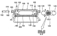
- FIG. 1 is a configuration diagram of an optical cable branch connection enclosure according to the present invention.
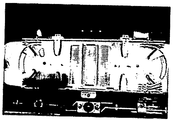
- FIG. 2 is a view illustrating the interior and application of the optical cable branch connection enclosure according to the present invention.
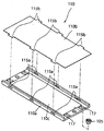
- FIG. 3 is a detailed configuration diagram of a unit sleeve storage plate for branching of the optical cable branch connection enclosure according to the present invention.
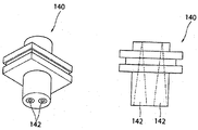
- FIG. 4 is a detailed configuration diagram of the 1-2 core core branch gasket of the optical cable branch connection enclosure according to the present invention.
- FIG. 5 is a configuration diagram of a cable holder of the optical cable branch connection enclosure according to the present invention.
- FIG. 6 is a view of another embodiment of a dummy cable sleeve filter board according to the present invention.
- the optical cable branch connection enclosure 10 includes a front cover 200 and a rear cover 100 which are rotated and opened with respect to the hinge H1.
- the optical cable branch connection enclosure 10 is provided with a housing processing hanger 105 for attaching the housing to a barbed wire or the like.
- a cable fixing support 130 for fixing the existing optical cable 1 is installed outside both side ends of the rear cover 100.
- the cable fixing support 130 is fixed to the enclosure 100 through the enclosure fixing screw groove 134 as shown in FIG.
- the cable fixing support 130 is provided with two locking jaws 132 for fixing the existing optical cable (1) in duplicate.
- the existing optical cable 1 is fixed in a cable fixing support 130, for example, bundled in a double by a sus (SUS) band 136, at this time, the locking jaw 132 is a susband 136 is a cable fixing support 130 ) To prevent escaping.
- the reason for fixing the existing optical cable 1 to the enclosure 100 through the locking step 132 as described above, when the existing optical cable is already bundled with one susband to fix the optical cable is often separated from the cable fixing support Because.
- the cable fixing support 130 is preferably made of steel or zinc steel.
- the existing optical cable 1 is fixed to the enclosure 100 through the locking step 132 in a double manner, it may help to reduce the size of the enclosure, which is the main object of the present invention.
- the present invention by securely fixed to the existing optical cable 1 from the outside through the cable fixing support 130 in two, only the part of the outer shell of the existing optical cable (1) can be installed inside the enclosure (1) Therefore, the length size of the enclosure 1 can be reduced by that much.
- the optical cable inside the enclosure 1 is installed with the outer shell removed, and the optical cable 1-1 including the unit in use passes through the interior of the enclosure as shown in FIG. 2.
- branch unit 1-2 for branch connection to the new subscriber is fixed to the branch unit sleeve storage plate 110.
- optical cable 1 applied to the present invention typically includes six units, each of which contains 6-12 cores.
- the branch sleeve storage plate 110 is installed inside the rear cover 100. It will be apparent to those skilled in the art that the branch unit sleeve storage plate 110 is provided with mounting means (not shown) for installing the branch sleeve storage plate 110 to the rear cover 100 of the housing.
- the support part 112 is a kind of sleeve, and is preferably a metal material attached to the rubber magnet plate 110c.
- the cores of the branching unit 1-2 may be freely installed by the rubber magnet plate 110c, and the cores may also be freely fixed and arranged.
- the supporting unit 112 is freely installed as a sleeve in the branching unit sleeve storage plate 110, and cores of the branching unit 1-2 are arranged in the supporting unit 112. It is fixed.
- an inlet groove 102 for introducing the branch unit 1-2 is preferably formed.
- the branch sleeve storage plate 110 for branching is interposed between the lower plate 110a and the upper plate 110b and the lower plate 110a and the upper plate 110b made of plastic. That is, it consists of a sponge (not shown) and the rubber magnet plate 110c to freely fix the support.
- the rubber magnet plate 110c is interposed, it is obvious that the members of the support part 112 and the support groove 113 for forming the plurality of sleeves may be a metal material attached to the magnet.
- the metal sleeves may be freely installed by the rubber magnet plate 110c. Since the sleeves can be variously configured by those skilled in the art, a detailed description thereof will be omitted.
- the sleeve used in the present invention may be any type as long as it can insert and fix the core wire of the optical cable.
- a plurality of insertion protrusions 115b are formed at the edge of the upper plate 110b, and the insertion protrusions 115b are inserted into and fixed in the insertion grooves 115a formed in the lower plate 110a, so that the upper plate 110b and the lower plate ( 110a), a sponge (not shown), and the rubber magnetic plate 110c are integrally coupled.
- a tie groove 117 may be formed in the lower plate 110a to fix the core wires of the branching unit 1-2 with a tie.
- Branch unit sleeve storage plate 110 may be coupled to the back cover 100 through a variety of known techniques.
- the fixing groove 118 may be formed in the lower plate 110a, and the fixing groove 118 may be screwed or bolted through the fixing groove, and in some cases, the fixing groove 118 may be fixed through the one-touch fixing pin 105. .
- the present invention uses a dummy optical cable (2-2).
- the dummy optical cable 2-2 needs a sufficient length for the branch connection work, for example, it may be preferable to have a length of at least twice as long as the length of the housing 10.
- the core wires c2 included in the dummy optical cable 2-2 are stored in the dummy cable sleeve filter board 120 as shown in FIG. 2.
- the dummy cable sleeve fitting plate 120 includes a support plate 122 provided with a plurality of sleeves 125 formed of a plurality of support portions and support grooves for fixing and supporting the core wires c2 of the dummy optical cable 2-2, It consists of a winding disc 124 for winding the core wires c2 of the dummy optical cable 2-2.
- the sleeve 125 formed on the dummy cable sleeve female plate 120 may be any type as long as the sleeve of the dummy optical cable can be inserted and fixed like the sleeve formed on the storage plate 110. Since it can be easily formed through a known technique, a detailed description thereof will be omitted herein.
- the dummy cable sleeve filter plate 120 is connected to the bottom surface of the rear cover 100 by a hinge (H2) is rotated to open and close to the storage plate 110.
- the dummy cable sleeve filter plate 120 is not limited thereto, and may have a configuration as shown in FIG. Of course, it is possible to have other various forms of variation.
- Both ends of each of the core wires c2 of the dummy optical cable 2-2 are connected to the branch unit core wire c1 and branched to a new cable for a new subscriber, which will be described in detail as follows.
- the middle portion of the branching unit 1-2 is cut in order to connect and connect both ends of the cores c2 of the dummy optical cable 2-2 to the cores c1 of the branching unit 1-2. do.
- both ends of the core wires c1 of the branching unit 1-2 cut according to a known technique and both ends of the dummy optical cable 2-2 core wire c2. Connect and connect each.
- the cores of the branching unit 1-2 extend by the length of the dummy optical cable cores.
- the core wires c1 of the branching unit 1-2 are connected to the core wires c2 of the dummy optical cable 2-2 and fixedly arranged on the storage plate 110 and the filter board 120.
- the branching of the new cable for the new subscriber is required, by selecting one of the core wires (c2) of the dummy optical cable (2-2) fixed to the filter board 120 through the branching gasket 140 It is connected to the core wire of the optical cable (not shown) for the incoming 1-2 core wire subscriber branch. It will be apparent to those skilled in the art that one side of the 1-2 core subscriber branch optical cable is connected to a new subscriber.
- the subscriber branch gasket 140 is preferably made of a rubber material. As shown in FIG. 4, the subscriber branch gasket 140 is formed by drilling a conical groove 142 to smoothly pull in and waterproof the 1-2-core subscriber branch optical cable. The conical groove is preferably formed about four per gasket.
- the subscriber branch gasket 140 contains 6-12 core wires per unit of the optical cable, it is preferable to install about 4 per enclosure.
- the core wires of the branch unit fixed to the branch unit storage plate 110 for branching can be manufactured to a size of about 500mm * 140mm * 70mm by using a three-dimensional method of collectively fixing the dummy cable sleeve mounting plate 120.
Landscapes
- Physics & Mathematics (AREA)
- General Physics & Mathematics (AREA)
- Optics & Photonics (AREA)
- Light Guides In General And Applications Therefor (AREA)
Applications Claiming Priority (2)
| Application Number | Priority Date | Filing Date | Title |
|---|---|---|---|
| KR1020110145645A KR101158256B1 (ko) | 2011-12-29 | 2011-12-29 | 광케이블 분기 접속 함체 |
| KR10-2011-0145645 | 2011-12-29 |
Publications (1)
| Publication Number | Publication Date |
|---|---|
| WO2013100445A1 true WO2013100445A1 (fr) | 2013-07-04 |
Family
ID=46689208
Family Applications (1)
| Application Number | Title | Priority Date | Filing Date |
|---|---|---|---|
| PCT/KR2012/010801 Ceased WO2013100445A1 (fr) | 2011-12-29 | 2012-12-12 | Fermeture de connexion pour dérivation de câble optique |
Country Status (2)
| Country | Link |
|---|---|
| KR (1) | KR101158256B1 (fr) |
| WO (1) | WO2013100445A1 (fr) |
Families Citing this family (2)
| Publication number | Priority date | Publication date | Assignee | Title |
|---|---|---|---|---|
| KR101451606B1 (ko) | 2013-04-17 | 2014-10-23 | 빛샘전자주식회사 | 중간분기용 무여장 광접속함체에서의 광케이블 분기 방법 |
| KR20250156891A (ko) | 2024-04-25 | 2025-11-04 | 유씨엘 주식회사 | 광케이블 중간분기함체와 중간분기 단자함 및 이의 광케이블 중간분기방법 |
Citations (4)
| Publication number | Priority date | Publication date | Assignee | Title |
|---|---|---|---|---|
| JP2008009093A (ja) * | 2006-06-28 | 2008-01-17 | Fujikura Ltd | 光接続箱 |
| KR20080046092A (ko) * | 2007-11-07 | 2008-05-26 | 주식회사 에이제이월드 | 광접속함체 |
| JP2008233695A (ja) * | 2007-03-22 | 2008-10-02 | Chugoku Electric Power Co Inc:The | Opgw用接続箱およびopgwの接続方法 |
| KR20100024599A (ko) * | 2008-08-26 | 2010-03-08 | 주식회사 엘지파워콤 | 광케이블 접속 분배함 및 그 광케이블 접속 분배함의 함체에 광 케이블을 결합하는 방법 |
-
2011
- 2011-12-29 KR KR1020110145645A patent/KR101158256B1/ko not_active Expired - Fee Related
-
2012
- 2012-12-12 WO PCT/KR2012/010801 patent/WO2013100445A1/fr not_active Ceased
Patent Citations (4)
| Publication number | Priority date | Publication date | Assignee | Title |
|---|---|---|---|---|
| JP2008009093A (ja) * | 2006-06-28 | 2008-01-17 | Fujikura Ltd | 光接続箱 |
| JP2008233695A (ja) * | 2007-03-22 | 2008-10-02 | Chugoku Electric Power Co Inc:The | Opgw用接続箱およびopgwの接続方法 |
| KR20080046092A (ko) * | 2007-11-07 | 2008-05-26 | 주식회사 에이제이월드 | 광접속함체 |
| KR20100024599A (ko) * | 2008-08-26 | 2010-03-08 | 주식회사 엘지파워콤 | 광케이블 접속 분배함 및 그 광케이블 접속 분배함의 함체에 광 케이블을 결합하는 방법 |
Also Published As
| Publication number | Publication date |
|---|---|
| KR101158256B1 (ko) | 2012-06-19 |
Similar Documents
| Publication | Publication Date | Title |
|---|---|---|
| US7751675B2 (en) | Wall box adapted to be mounted at a mid-span access location of a telecommunications cable | |
| US6766094B2 (en) | Aerial closure for local convergence point | |
| US6778752B2 (en) | Below grade closure for local convergence point | |
| EP1616210B1 (fr) | Armoire de convergence locale pour reseaux de cables en fibre optique | |
| US7668432B2 (en) | Multi-drop closure systems and methods for fiber optic cabling | |
| RU171105U1 (ru) | Оптоволоконный распределительный терминал | |
| US20110097052A1 (en) | Fiber Access Terminal Mounted at a Mid-Span Access Location of a Telecommunications Cable | |
| EP1316829A2 (fr) | Terminal de distribution de fibres optiques pour point d'accès à un réseau | |
| US7340144B2 (en) | Optical fiber splice enclosure | |
| JP2008502946A (ja) | 一体型ケーブル処理シール特徴部を備えた光ファイバクロージャ | |
| EP2087389A2 (fr) | Dispositif interface de réseau | |
| WO2016048004A1 (fr) | Compartiment de stockage de fibres optiques empilées | |
| US12392965B2 (en) | Compact splice enclosure with improved access to adapters | |
| CN102792205B (zh) | 用于多层住宅单元的光纤配给网 | |
| WO2013100445A1 (fr) | Fermeture de connexion pour dérivation de câble optique | |
| KR200294692Y1 (ko) | 광단자함 | |
| US12444915B2 (en) | Management device for hybrid cable | |
| CN221551557U (zh) | 一种复合蝶形引入光缆 | |
| EP2124080A1 (fr) | Systeme de cablage optique | |
| US9835814B2 (en) | Fiber termination point with overlength storage | |
| KR20250144634A (ko) | 노후 건물 초고속 정보통신 가입자선의 정비방법 | |
| CN104142550B (zh) | 一种具填缝防水辅助装置的光缆接线壳 | |
| JP2008171003A (ja) | 集合住宅(mdu)および商業ビルへの配設のための光ファイバ配線 | |
| WO2014196699A1 (fr) | Coffre de rangement de fils centraux optiques multicouches | |
| WO2015126157A1 (fr) | Câble intégré pour communication de données |
Legal Events
| Date | Code | Title | Description |
|---|---|---|---|
| 121 | Ep: the epo has been informed by wipo that ep was designated in this application |
Ref document number: 12861555 Country of ref document: EP Kind code of ref document: A1 |
|
| NENP | Non-entry into the national phase |
Ref country code: DE |
|
| 122 | Ep: pct application non-entry in european phase |
Ref document number: 12861555 Country of ref document: EP Kind code of ref document: A1 |