WO2013102960A1 - Dispositif de commande pour véhicule électrique, et véhicule électrique - Google Patents
Dispositif de commande pour véhicule électrique, et véhicule électrique Download PDFInfo
- Publication number
- WO2013102960A1 WO2013102960A1 PCT/JP2012/003954 JP2012003954W WO2013102960A1 WO 2013102960 A1 WO2013102960 A1 WO 2013102960A1 JP 2012003954 W JP2012003954 W JP 2012003954W WO 2013102960 A1 WO2013102960 A1 WO 2013102960A1
- Authority
- WO
- WIPO (PCT)
- Prior art keywords
- battery
- electric vehicle
- converter
- voltage
- control device
- Prior art date
- Legal status (The legal status is an assumption and is not a legal conclusion. Google has not performed a legal analysis and makes no representation as to the accuracy of the status listed.)
- Ceased
Links
Images


Classifications
-
- B—PERFORMING OPERATIONS; TRANSPORTING
- B60—VEHICLES IN GENERAL
- B60L—PROPULSION OF ELECTRICALLY-PROPELLED VEHICLES; SUPPLYING ELECTRIC POWER FOR AUXILIARY EQUIPMENT OF ELECTRICALLY-PROPELLED VEHICLES; ELECTRODYNAMIC BRAKE SYSTEMS FOR VEHICLES IN GENERAL; MAGNETIC SUSPENSION OR LEVITATION FOR VEHICLES; MONITORING OPERATING VARIABLES OF ELECTRICALLY-PROPELLED VEHICLES; ELECTRIC SAFETY DEVICES FOR ELECTRICALLY-PROPELLED VEHICLES
- B60L58/00—Methods or circuit arrangements for monitoring or controlling batteries or fuel cells, specially adapted for electric vehicles
- B60L58/10—Methods or circuit arrangements for monitoring or controlling batteries or fuel cells, specially adapted for electric vehicles for monitoring or controlling batteries
- B60L58/12—Methods or circuit arrangements for monitoring or controlling batteries or fuel cells, specially adapted for electric vehicles for monitoring or controlling batteries responding to state of charge [SoC]
-
- B—PERFORMING OPERATIONS; TRANSPORTING
- B60—VEHICLES IN GENERAL
- B60L—PROPULSION OF ELECTRICALLY-PROPELLED VEHICLES; SUPPLYING ELECTRIC POWER FOR AUXILIARY EQUIPMENT OF ELECTRICALLY-PROPELLED VEHICLES; ELECTRODYNAMIC BRAKE SYSTEMS FOR VEHICLES IN GENERAL; MAGNETIC SUSPENSION OR LEVITATION FOR VEHICLES; MONITORING OPERATING VARIABLES OF ELECTRICALLY-PROPELLED VEHICLES; ELECTRIC SAFETY DEVICES FOR ELECTRICALLY-PROPELLED VEHICLES
- B60L15/00—Methods, circuits, or devices for controlling the traction-motor speed of electrically-propelled vehicles
- B60L15/007—Physical arrangements or structures of drive train converters specially adapted for the propulsion motors of electric vehicles
-
- B—PERFORMING OPERATIONS; TRANSPORTING
- B60—VEHICLES IN GENERAL
- B60L—PROPULSION OF ELECTRICALLY-PROPELLED VEHICLES; SUPPLYING ELECTRIC POWER FOR AUXILIARY EQUIPMENT OF ELECTRICALLY-PROPELLED VEHICLES; ELECTRODYNAMIC BRAKE SYSTEMS FOR VEHICLES IN GENERAL; MAGNETIC SUSPENSION OR LEVITATION FOR VEHICLES; MONITORING OPERATING VARIABLES OF ELECTRICALLY-PROPELLED VEHICLES; ELECTRIC SAFETY DEVICES FOR ELECTRICALLY-PROPELLED VEHICLES
- B60L15/00—Methods, circuits, or devices for controlling the traction-motor speed of electrically-propelled vehicles
- B60L15/02—Methods, circuits, or devices for controlling the traction-motor speed of electrically-propelled vehicles characterised by the form of the current used in the control circuit
- B60L15/025—Methods, circuits, or devices for controlling the traction-motor speed of electrically-propelled vehicles characterised by the form of the current used in the control circuit using field orientation; Vector control; Direct Torque Control [DTC]
-
- B—PERFORMING OPERATIONS; TRANSPORTING
- B60—VEHICLES IN GENERAL
- B60L—PROPULSION OF ELECTRICALLY-PROPELLED VEHICLES; SUPPLYING ELECTRIC POWER FOR AUXILIARY EQUIPMENT OF ELECTRICALLY-PROPELLED VEHICLES; ELECTRODYNAMIC BRAKE SYSTEMS FOR VEHICLES IN GENERAL; MAGNETIC SUSPENSION OR LEVITATION FOR VEHICLES; MONITORING OPERATING VARIABLES OF ELECTRICALLY-PROPELLED VEHICLES; ELECTRIC SAFETY DEVICES FOR ELECTRICALLY-PROPELLED VEHICLES
- B60L15/00—Methods, circuits, or devices for controlling the traction-motor speed of electrically-propelled vehicles
- B60L15/20—Methods, circuits, or devices for controlling the traction-motor speed of electrically-propelled vehicles for control of the vehicle or its driving motor to achieve a desired performance, e.g. speed, torque, programmed variation of speed
-
- B—PERFORMING OPERATIONS; TRANSPORTING
- B60—VEHICLES IN GENERAL
- B60L—PROPULSION OF ELECTRICALLY-PROPELLED VEHICLES; SUPPLYING ELECTRIC POWER FOR AUXILIARY EQUIPMENT OF ELECTRICALLY-PROPELLED VEHICLES; ELECTRODYNAMIC BRAKE SYSTEMS FOR VEHICLES IN GENERAL; MAGNETIC SUSPENSION OR LEVITATION FOR VEHICLES; MONITORING OPERATING VARIABLES OF ELECTRICALLY-PROPELLED VEHICLES; ELECTRIC SAFETY DEVICES FOR ELECTRICALLY-PROPELLED VEHICLES
- B60L3/00—Electric devices on electrically-propelled vehicles for safety purposes; Monitoring operating variables, e.g. speed, deceleration or energy consumption
- B60L3/0023—Detecting, eliminating, remedying or compensating for drive train abnormalities, e.g. failures within the drive train
- B60L3/0046—Detecting, eliminating, remedying or compensating for drive train abnormalities, e.g. failures within the drive train relating to electric energy storage systems, e.g. batteries or capacitors
-
- B—PERFORMING OPERATIONS; TRANSPORTING
- B60—VEHICLES IN GENERAL
- B60L—PROPULSION OF ELECTRICALLY-PROPELLED VEHICLES; SUPPLYING ELECTRIC POWER FOR AUXILIARY EQUIPMENT OF ELECTRICALLY-PROPELLED VEHICLES; ELECTRODYNAMIC BRAKE SYSTEMS FOR VEHICLES IN GENERAL; MAGNETIC SUSPENSION OR LEVITATION FOR VEHICLES; MONITORING OPERATING VARIABLES OF ELECTRICALLY-PROPELLED VEHICLES; ELECTRIC SAFETY DEVICES FOR ELECTRICALLY-PROPELLED VEHICLES
- B60L50/00—Electric propulsion with power supplied within the vehicle
- B60L50/50—Electric propulsion with power supplied within the vehicle using propulsion power supplied by batteries or fuel cells
- B60L50/51—Electric propulsion with power supplied within the vehicle using propulsion power supplied by batteries or fuel cells characterised by AC-motors
-
- B—PERFORMING OPERATIONS; TRANSPORTING
- B60—VEHICLES IN GENERAL
- B60L—PROPULSION OF ELECTRICALLY-PROPELLED VEHICLES; SUPPLYING ELECTRIC POWER FOR AUXILIARY EQUIPMENT OF ELECTRICALLY-PROPELLED VEHICLES; ELECTRODYNAMIC BRAKE SYSTEMS FOR VEHICLES IN GENERAL; MAGNETIC SUSPENSION OR LEVITATION FOR VEHICLES; MONITORING OPERATING VARIABLES OF ELECTRICALLY-PROPELLED VEHICLES; ELECTRIC SAFETY DEVICES FOR ELECTRICALLY-PROPELLED VEHICLES
- B60L50/00—Electric propulsion with power supplied within the vehicle
- B60L50/50—Electric propulsion with power supplied within the vehicle using propulsion power supplied by batteries or fuel cells
- B60L50/53—Electric propulsion with power supplied within the vehicle using propulsion power supplied by batteries or fuel cells in combination with an external power supply, e.g. from overhead contact lines
-
- B—PERFORMING OPERATIONS; TRANSPORTING
- B60—VEHICLES IN GENERAL
- B60L—PROPULSION OF ELECTRICALLY-PROPELLED VEHICLES; SUPPLYING ELECTRIC POWER FOR AUXILIARY EQUIPMENT OF ELECTRICALLY-PROPELLED VEHICLES; ELECTRODYNAMIC BRAKE SYSTEMS FOR VEHICLES IN GENERAL; MAGNETIC SUSPENSION OR LEVITATION FOR VEHICLES; MONITORING OPERATING VARIABLES OF ELECTRICALLY-PROPELLED VEHICLES; ELECTRIC SAFETY DEVICES FOR ELECTRICALLY-PROPELLED VEHICLES
- B60L58/00—Methods or circuit arrangements for monitoring or controlling batteries or fuel cells, specially adapted for electric vehicles
- B60L58/10—Methods or circuit arrangements for monitoring or controlling batteries or fuel cells, specially adapted for electric vehicles for monitoring or controlling batteries
- B60L58/16—Methods or circuit arrangements for monitoring or controlling batteries or fuel cells, specially adapted for electric vehicles for monitoring or controlling batteries responding to battery ageing, e.g. to the number of charging cycles or the state of health [SoH]
-
- B—PERFORMING OPERATIONS; TRANSPORTING
- B60—VEHICLES IN GENERAL
- B60L—PROPULSION OF ELECTRICALLY-PROPELLED VEHICLES; SUPPLYING ELECTRIC POWER FOR AUXILIARY EQUIPMENT OF ELECTRICALLY-PROPELLED VEHICLES; ELECTRODYNAMIC BRAKE SYSTEMS FOR VEHICLES IN GENERAL; MAGNETIC SUSPENSION OR LEVITATION FOR VEHICLES; MONITORING OPERATING VARIABLES OF ELECTRICALLY-PROPELLED VEHICLES; ELECTRIC SAFETY DEVICES FOR ELECTRICALLY-PROPELLED VEHICLES
- B60L58/00—Methods or circuit arrangements for monitoring or controlling batteries or fuel cells, specially adapted for electric vehicles
- B60L58/10—Methods or circuit arrangements for monitoring or controlling batteries or fuel cells, specially adapted for electric vehicles for monitoring or controlling batteries
- B60L58/24—Methods or circuit arrangements for monitoring or controlling batteries or fuel cells, specially adapted for electric vehicles for monitoring or controlling batteries for controlling the temperature of batteries
- B60L58/25—Methods or circuit arrangements for monitoring or controlling batteries or fuel cells, specially adapted for electric vehicles for monitoring or controlling batteries for controlling the temperature of batteries by controlling the electric load
-
- B—PERFORMING OPERATIONS; TRANSPORTING
- B60—VEHICLES IN GENERAL
- B60L—PROPULSION OF ELECTRICALLY-PROPELLED VEHICLES; SUPPLYING ELECTRIC POWER FOR AUXILIARY EQUIPMENT OF ELECTRICALLY-PROPELLED VEHICLES; ELECTRODYNAMIC BRAKE SYSTEMS FOR VEHICLES IN GENERAL; MAGNETIC SUSPENSION OR LEVITATION FOR VEHICLES; MONITORING OPERATING VARIABLES OF ELECTRICALLY-PROPELLED VEHICLES; ELECTRIC SAFETY DEVICES FOR ELECTRICALLY-PROPELLED VEHICLES
- B60L9/00—Electric propulsion with power supply external to the vehicle
- B60L9/16—Electric propulsion with power supply external to the vehicle using AC induction motors
- B60L9/24—Electric propulsion with power supply external to the vehicle using AC induction motors fed from AC supply lines
- B60L9/28—Electric propulsion with power supply external to the vehicle using AC induction motors fed from AC supply lines polyphase motors
-
- B—PERFORMING OPERATIONS; TRANSPORTING
- B60—VEHICLES IN GENERAL
- B60L—PROPULSION OF ELECTRICALLY-PROPELLED VEHICLES; SUPPLYING ELECTRIC POWER FOR AUXILIARY EQUIPMENT OF ELECTRICALLY-PROPELLED VEHICLES; ELECTRODYNAMIC BRAKE SYSTEMS FOR VEHICLES IN GENERAL; MAGNETIC SUSPENSION OR LEVITATION FOR VEHICLES; MONITORING OPERATING VARIABLES OF ELECTRICALLY-PROPELLED VEHICLES; ELECTRIC SAFETY DEVICES FOR ELECTRICALLY-PROPELLED VEHICLES
- B60L2200/00—Type of vehicles
- B60L2200/26—Rail vehicles
-
- B—PERFORMING OPERATIONS; TRANSPORTING
- B60—VEHICLES IN GENERAL
- B60L—PROPULSION OF ELECTRICALLY-PROPELLED VEHICLES; SUPPLYING ELECTRIC POWER FOR AUXILIARY EQUIPMENT OF ELECTRICALLY-PROPELLED VEHICLES; ELECTRODYNAMIC BRAKE SYSTEMS FOR VEHICLES IN GENERAL; MAGNETIC SUSPENSION OR LEVITATION FOR VEHICLES; MONITORING OPERATING VARIABLES OF ELECTRICALLY-PROPELLED VEHICLES; ELECTRIC SAFETY DEVICES FOR ELECTRICALLY-PROPELLED VEHICLES
- B60L2210/00—Converter types
- B60L2210/10—DC to DC converters
- B60L2210/14—Boost converters
-
- B—PERFORMING OPERATIONS; TRANSPORTING
- B60—VEHICLES IN GENERAL
- B60L—PROPULSION OF ELECTRICALLY-PROPELLED VEHICLES; SUPPLYING ELECTRIC POWER FOR AUXILIARY EQUIPMENT OF ELECTRICALLY-PROPELLED VEHICLES; ELECTRODYNAMIC BRAKE SYSTEMS FOR VEHICLES IN GENERAL; MAGNETIC SUSPENSION OR LEVITATION FOR VEHICLES; MONITORING OPERATING VARIABLES OF ELECTRICALLY-PROPELLED VEHICLES; ELECTRIC SAFETY DEVICES FOR ELECTRICALLY-PROPELLED VEHICLES
- B60L2210/00—Converter types
- B60L2210/30—AC to DC converters
-
- B—PERFORMING OPERATIONS; TRANSPORTING
- B60—VEHICLES IN GENERAL
- B60L—PROPULSION OF ELECTRICALLY-PROPELLED VEHICLES; SUPPLYING ELECTRIC POWER FOR AUXILIARY EQUIPMENT OF ELECTRICALLY-PROPELLED VEHICLES; ELECTRODYNAMIC BRAKE SYSTEMS FOR VEHICLES IN GENERAL; MAGNETIC SUSPENSION OR LEVITATION FOR VEHICLES; MONITORING OPERATING VARIABLES OF ELECTRICALLY-PROPELLED VEHICLES; ELECTRIC SAFETY DEVICES FOR ELECTRICALLY-PROPELLED VEHICLES
- B60L2210/00—Converter types
- B60L2210/40—DC to AC converters
-
- B—PERFORMING OPERATIONS; TRANSPORTING
- B60—VEHICLES IN GENERAL
- B60L—PROPULSION OF ELECTRICALLY-PROPELLED VEHICLES; SUPPLYING ELECTRIC POWER FOR AUXILIARY EQUIPMENT OF ELECTRICALLY-PROPELLED VEHICLES; ELECTRODYNAMIC BRAKE SYSTEMS FOR VEHICLES IN GENERAL; MAGNETIC SUSPENSION OR LEVITATION FOR VEHICLES; MONITORING OPERATING VARIABLES OF ELECTRICALLY-PROPELLED VEHICLES; ELECTRIC SAFETY DEVICES FOR ELECTRICALLY-PROPELLED VEHICLES
- B60L2240/00—Control parameters of input or output; Target parameters
- B60L2240/10—Vehicle control parameters
- B60L2240/12—Speed
-
- B—PERFORMING OPERATIONS; TRANSPORTING
- B60—VEHICLES IN GENERAL
- B60L—PROPULSION OF ELECTRICALLY-PROPELLED VEHICLES; SUPPLYING ELECTRIC POWER FOR AUXILIARY EQUIPMENT OF ELECTRICALLY-PROPELLED VEHICLES; ELECTRODYNAMIC BRAKE SYSTEMS FOR VEHICLES IN GENERAL; MAGNETIC SUSPENSION OR LEVITATION FOR VEHICLES; MONITORING OPERATING VARIABLES OF ELECTRICALLY-PROPELLED VEHICLES; ELECTRIC SAFETY DEVICES FOR ELECTRICALLY-PROPELLED VEHICLES
- B60L2240/00—Control parameters of input or output; Target parameters
- B60L2240/40—Drive Train control parameters
- B60L2240/42—Drive Train control parameters related to electric machines
- B60L2240/423—Torque
-
- B—PERFORMING OPERATIONS; TRANSPORTING
- B60—VEHICLES IN GENERAL
- B60L—PROPULSION OF ELECTRICALLY-PROPELLED VEHICLES; SUPPLYING ELECTRIC POWER FOR AUXILIARY EQUIPMENT OF ELECTRICALLY-PROPELLED VEHICLES; ELECTRODYNAMIC BRAKE SYSTEMS FOR VEHICLES IN GENERAL; MAGNETIC SUSPENSION OR LEVITATION FOR VEHICLES; MONITORING OPERATING VARIABLES OF ELECTRICALLY-PROPELLED VEHICLES; ELECTRIC SAFETY DEVICES FOR ELECTRICALLY-PROPELLED VEHICLES
- B60L2240/00—Control parameters of input or output; Target parameters
- B60L2240/40—Drive Train control parameters
- B60L2240/54—Drive Train control parameters related to batteries
- B60L2240/547—Voltage
-
- B—PERFORMING OPERATIONS; TRANSPORTING
- B60—VEHICLES IN GENERAL
- B60L—PROPULSION OF ELECTRICALLY-PROPELLED VEHICLES; SUPPLYING ELECTRIC POWER FOR AUXILIARY EQUIPMENT OF ELECTRICALLY-PROPELLED VEHICLES; ELECTRODYNAMIC BRAKE SYSTEMS FOR VEHICLES IN GENERAL; MAGNETIC SUSPENSION OR LEVITATION FOR VEHICLES; MONITORING OPERATING VARIABLES OF ELECTRICALLY-PROPELLED VEHICLES; ELECTRIC SAFETY DEVICES FOR ELECTRICALLY-PROPELLED VEHICLES
- B60L2240/00—Control parameters of input or output; Target parameters
- B60L2240/40—Drive Train control parameters
- B60L2240/54—Drive Train control parameters related to batteries
- B60L2240/549—Current
-
- B—PERFORMING OPERATIONS; TRANSPORTING
- B60—VEHICLES IN GENERAL
- B60L—PROPULSION OF ELECTRICALLY-PROPELLED VEHICLES; SUPPLYING ELECTRIC POWER FOR AUXILIARY EQUIPMENT OF ELECTRICALLY-PROPELLED VEHICLES; ELECTRODYNAMIC BRAKE SYSTEMS FOR VEHICLES IN GENERAL; MAGNETIC SUSPENSION OR LEVITATION FOR VEHICLES; MONITORING OPERATING VARIABLES OF ELECTRICALLY-PROPELLED VEHICLES; ELECTRIC SAFETY DEVICES FOR ELECTRICALLY-PROPELLED VEHICLES
- B60L2270/00—Problem solutions or means not otherwise provided for
- B60L2270/20—Inrush current reduction, i.e. avoiding high currents when connecting the battery
-
- Y—GENERAL TAGGING OF NEW TECHNOLOGICAL DEVELOPMENTS; GENERAL TAGGING OF CROSS-SECTIONAL TECHNOLOGIES SPANNING OVER SEVERAL SECTIONS OF THE IPC; TECHNICAL SUBJECTS COVERED BY FORMER USPC CROSS-REFERENCE ART COLLECTIONS [XRACs] AND DIGESTS
- Y02—TECHNOLOGIES OR APPLICATIONS FOR MITIGATION OR ADAPTATION AGAINST CLIMATE CHANGE
- Y02T—CLIMATE CHANGE MITIGATION TECHNOLOGIES RELATED TO TRANSPORTATION
- Y02T10/00—Road transport of goods or passengers
- Y02T10/60—Other road transportation technologies with climate change mitigation effect
- Y02T10/64—Electric machine technologies in electromobility
-
- Y—GENERAL TAGGING OF NEW TECHNOLOGICAL DEVELOPMENTS; GENERAL TAGGING OF CROSS-SECTIONAL TECHNOLOGIES SPANNING OVER SEVERAL SECTIONS OF THE IPC; TECHNICAL SUBJECTS COVERED BY FORMER USPC CROSS-REFERENCE ART COLLECTIONS [XRACs] AND DIGESTS
- Y02—TECHNOLOGIES OR APPLICATIONS FOR MITIGATION OR ADAPTATION AGAINST CLIMATE CHANGE
- Y02T—CLIMATE CHANGE MITIGATION TECHNOLOGIES RELATED TO TRANSPORTATION
- Y02T10/00—Road transport of goods or passengers
- Y02T10/60—Other road transportation technologies with climate change mitigation effect
- Y02T10/70—Energy storage systems for electromobility, e.g. batteries
-
- Y—GENERAL TAGGING OF NEW TECHNOLOGICAL DEVELOPMENTS; GENERAL TAGGING OF CROSS-SECTIONAL TECHNOLOGIES SPANNING OVER SEVERAL SECTIONS OF THE IPC; TECHNICAL SUBJECTS COVERED BY FORMER USPC CROSS-REFERENCE ART COLLECTIONS [XRACs] AND DIGESTS
- Y02—TECHNOLOGIES OR APPLICATIONS FOR MITIGATION OR ADAPTATION AGAINST CLIMATE CHANGE
- Y02T—CLIMATE CHANGE MITIGATION TECHNOLOGIES RELATED TO TRANSPORTATION
- Y02T10/00—Road transport of goods or passengers
- Y02T10/60—Other road transportation technologies with climate change mitigation effect
- Y02T10/72—Electric energy management in electromobility
Definitions
- the present embodiment relates to an electric vehicle control device and an electric vehicle.
- An electric railway vehicle is driven using electric power supplied from an overhead line through a pantograph.
- an overhead line is installed on the premises line in the garage or the pit line for maintenance.
- a diesel-powered locomotive that does not require overhead power pushes the electric vehicle into the pit line.
- a diesel-powered locomotive is required every time an electric vehicle needs to be pushed into the pit line, resulting in poor work efficiency.
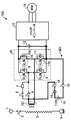
- FIG. 1 is a diagram illustrating a main circuit configuration of an electric vehicle control device for an electric vehicle according to a first embodiment.
- FIG. 2 is a diagram illustrating a step-up chopper to which a part of the configuration included in the AC / DC converter included in the electric vehicle control device according to the first embodiment is applied.
- FIG. 3 is a diagram showing a main circuit configuration for controlling the step-up chopper in the electric vehicle control apparatus according to the first embodiment.
- Figure 4 is a diagram showing an example of a switching signal Q Y produced in accordance with the relationship between the voltage command value and the triangular wave.
- Figure 5 is a diagram showing an example of discharge current I BATT increasing or decreasing in accordance with the on / off cycle of the switching signal Q Y.
- FIG. 1 is a diagram illustrating a main circuit configuration of an electric vehicle control device for an electric vehicle according to a first embodiment.
- FIG. 2 is a diagram illustrating a step-up chopper to which a part of the configuration included
- FIG. 6 is a diagram illustrating a configuration for controlling the VVVF inverter of the electric vehicle control apparatus according to the first embodiment.
- FIG. 7 is a diagram showing a main circuit configuration of the electric vehicle control device according to the second embodiment.
- FIG. 8 is a diagram illustrating a step-up chopper to which a part of the configuration included in the AC / DC converter included in the electric vehicle control device according to the second embodiment is applied.
- FIG. 9 is a diagram illustrating a main circuit configuration of the electric vehicle control device according to the third embodiment.
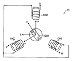
- FIG. 10 is a diagram illustrating an example of a driving main motor that is driven by electric power supplied from a VVVF inverter.
- FIG. 11 is a diagram showing the relationship between the D-axis current and the Q-axis current necessary for outputting the same torque, and the loss.
- the electric vehicle control device of one embodiment has a diode and a switching element that convert alternating current or direct current voltage supplied from the input side into direct current voltage, and a converter to which the main motor is connected to the output side via an inverter; A battery connected to the converter via a reactor and supplying power to the main motor; a diode included in the converter; and the switching element, and a boost chopper circuit for boosting the voltage of the battery.
- an electric vehicle control device that can be downsized while having a function of boosting a battery.
- FIG. 1 is a diagram illustrating a main circuit configuration of an electric vehicle control apparatus 100 for an electric vehicle according to the first embodiment.
- the electric vehicle control apparatus 100 is connected to a current collector (hereinafter referred to as a pantograph) 1 to an AC overhead line (not shown) and supplied with electric power.
- a current collector hereinafter referred to as a pantograph
- the pantograph 1 the AC high speed circuit breaker 2, and the transformer 3 are connected to the overhead line side.
- the negative side of the transformer 3 is grounded through the wheel 4.
- the transformer 3 transforms an AC voltage supplied from the AC overhead line via the pantograph 1 and supplies the transformed AC voltage to the AC / DC converter 20 side.
- the electric vehicle control device 100 includes a charging resistor charging contactor 5, a charging resistor short-circuiting contactor 6, a charging resistor 7, an AC / DC on the secondary side of the transformer 3. Converter 20. Further, the electric vehicle control device 100 includes a filter capacitor 12 and a VVVF inverter 13 on the DC side of the AC / DC converter 20. Furthermore, the electric vehicle control device 100 includes a drive main motor (MM) 14 on the AC side of the VVVF inverter 13. Further, the electric vehicle control device 100 includes a control power supply battery 15, a backflow prevention diode 16, a reactor 17, a plus side open contactor 18, and a minus side open contactor 19.
- Control power supply battery 15 (hereinafter also referred to as battery 15) is a battery that supplies power to various systems controlled by electric vehicle control device 100 or the like.
- the control power supply battery 15 according to the present embodiment is further used to supply power to the VVVF inverter 13 when the electric vehicle moves in a place without an overhead line.
- the control power supply battery 15 is normally fully charged because it is charged from a charger (not shown) when there is a power supply source such as an overhead wire or a third rail.
- the AC / DC converter 20 has two phases, a U phase and a V phase.
- the U phase includes a U phase upper element 8 and a U phase lower element 9.
- the V phase includes a V phase upper element 10 and a V phase lower element 11.
- diodes (10a, 11a) and switching elements (10b, 11b) such as IGBTs are connected in antiparallel. Configured.
- the configuration included in the V phase is used as the boost chopper circuit having the boosting function of the battery 15 will be described, but the configuration included in the U phase may be used.
- the electric vehicle control apparatus 100 when the electric vehicle travels in a place with an overhead line, the AC high-speed circuit breaker 2, the charging resistor charging contactor 5, and the charging resistor short-circuiting contactor 6 are connected. The plus side open contactor 18 and the minus side open contactor 19 are opened. Thereby, the electric power supplied from the transformer 3 is supplied to the AC / DC converter 20 via the charging resistor 7. The AC / DC converter 20 converts the AC voltage of the supplied power into a DC voltage. Then, power is supplied from the AC / DC converter 20 to the filter capacitor 12 and the VVVF inverter 13 arranged in parallel.
- the VVVF inverter 13 converts the DC voltage output from the AC / DC converter 20 into an AC voltage having a variable voltage and a variable frequency, and supplies the AC voltage to the driving main motor 14 that drives the electric vehicle. Thereby, the electric vehicle can drive
- the battery 15 needs to be driven by the battery 15.
- the electric vehicle control apparatus 100 is connected to the AC / DC converter 20 and the battery 15, and uses the semiconductor element necessary for boosting the boost chopper and the semiconductor element of the AC / DC converter in common.
- the converter and the step-up chopper are integrated. The contents will be described below.
- FIG. 2 is a diagram showing a step-up chopper to which a part of the configuration included in the AC / DC converter 20 included in the electric vehicle control device 100 is applied.
- the boost chopper circuit 201 is realized by the configuration on the path indicated by the thick line. That is, the boost chopper circuit 201 is included in the battery 15, the backflow prevention diode 16, the reactor 17, the switching element (for example, IGBT) 11 b included in the V-phase lower element 11, and the V-phase upper element 10. It comprises a diode 10a and a filter capacitor 12. As shown in FIG. 2, the switching element 10 b and the diode 10 a included in the V-phase upper element 10 are shared with the AC / DC converter 20.
- the reactor 17 used in the step-up chopper circuit 201 is determined by the battery discharge current and the switching frequency. For example, if the travel by the battery 15 is limited to about 3 km / h and the driving force is limited to about 1/5 of the maximum driving force, the power consumption is about 30 kw. If the voltage of the battery 15 is 110 V, the battery discharge current is 270 A, the switching frequency is 500 Hz, and the allowable current pulsation is ⁇ 50 A, that is, 100 A between the peaks, it may be about 1 mH. For this reason, in this embodiment, the reactor 17 having an inductance value of 1 mH and a rated current of 270 A may be selected. Therefore, the additional parts are not large parts that affect the overall size of the electric vehicle control device 100.
- the backflow prevention diode 16 is provided to suppress charging of the battery 15 due to backflow of current.
- the pantograph 1 When the electric vehicle according to the present embodiment moves in a place where there is no overhead line, the pantograph 1 is lowered by the operation of switching to battery running, and power is supplied from the control power supply battery 15 to the VVVF inverter 13. As such, the circuit is connected.
- the electric vehicle control device 100 opens the AC high-speed circuit breaker 2, the charging resistor charging contactor 5 and the charging resistor short-circuiting contactor 6, and opens the plus-side opening contactor 18 and the minus-side opening contactor 19. Connecting.
- the step-up chopper circuit 201 performs step-up according to the conduction rate of the switching element 11b.
- the electric vehicle control apparatus 100 can charge the filter capacitor 12 after the boost chopper circuit 201 boosts the voltage to 200V to 300V. . Since electric power is supplied to the VVVF inverter 13 with the boosted voltage, the driving main motor 14 can be driven. Thereby, the electric vehicle control device 100 can move the electric vehicle on which the electric vehicle control device 100 is mounted in a place where there is no overhead line.
- FIG. 3 is a diagram showing a main circuit configuration for controlling the step-up chopper circuit 201 in the electric vehicle control apparatus 100.
- the main circuit configuration shown in FIG. 3 includes a switch control unit 301 and operates by energization from the battery 15.
- the configuration shown in FIG. 3 is shown as an example of a control system for controlling the boost chopper circuit 201, and another control system may be used.
- the switch control unit 301 shown in FIG. 3 turns on / off the switching element 11b included in the V-phase lower element 11 so that the discharge current I BATT from the battery 15 flows. That is, when the switch control unit 301 turns on the switching element 11 b included in the V-phase lower element 11, the battery 15 is short-circuited via the reactor 17, so that the current increases. After that, when the switching element 11b is turned off, the switch controller 301 causes the current stored in the reactor 17 to flow into the filter capacitor 12 through the diode 10a side of the V-phase upper element 10. At this time, the discharge current I BATT gradually decreases. When the switch control unit 301 turns on the switching element 11b included in the V-phase lower element 11 again, the discharge current I BATT starts to increase.
- this operation is repeated, and the current from the battery 15 is charged to the filter capacitor 12.
- the switch control unit 301 appropriately changes the ON / OFF cycle of the switching element 11b of the V-phase lower element 11, in other words, the conduction ratio, thereby changing the voltage of the filter capacitor 12 to the battery 15. Can be higher than voltage.
- a filter capacitor voltage necessary for driving the driving main motor 14 is predetermined as a command value (also referred to as a filter capacitor voltage command value).
- a command value also referred to as a filter capacitor voltage command value.
- 300V is set as the filter capacitor voltage command value.
- the subtractor 311 inputs a differential voltage value obtained by subtracting the voltage measured from the filter capacitor 12 from the filter capacitor voltage command value to the proportional-plus-integral controller (PI) 312. Then, the proportional-plus-integral controller 312 calculates a command value (battery discharge current command value) that determines the discharge current flowing from the battery 15 from the input differential voltage value.
- PI proportional-plus-integral controller
- the subtractor 313 inputs a differential current value obtained by subtracting the actual battery discharge current value from the battery discharge current command value to the proportional-plus-integral controller (PI) 314.
- the proportional-plus-integral controller 314 calculates the conduction ratio of the switching element 11b of the step-up chopper circuit 201 (time ratio during which the switching element 11b is turned on) from the input differential current value.
- PWM signal generator 315 a technique such as comparing the duty ratio and the triangular wave, so that the predetermined switching frequency, and generates a switching signal Q Y of the switching element 11b.
- FIG. 4 is a diagram showing an example of a switching signal Q Y produced in accordance with the relationship between the voltage command value and the triangular wave.
- PWM signal generator 315 compares the duty ratio and the triangular wave, the time the duty ratio is larger than the triangular wave and outputs a switching signal Q Y as an on, the voltage command value or less of the triangular wave the time to output as an off-switching signal Q Y.
- the switching element 11b in accordance with the switching signal Q Y, ON / OFF periods are controlled.
- FIG. 5 is a diagram showing an example of discharge current I BATT increasing or decreasing in accordance with the on / off cycle of the switching signal Q Y. As shown in FIG. 5, in the time zone of the switching signal Q Y is turned on, the discharge current I BATT gradually increases, the switching signal Q Y is at off hours, the discharge current I BATT decreases gradually.
- the electric vehicle control device 100 has a configuration for controlling the inverter 13 in accordance with the voltage of the battery 15.
- FIG. 6 is a diagram showing a configuration for controlling the VVVF inverter 13 of the electric vehicle control apparatus 100.
- the electric vehicle control device 100 includes a battery SOC (State of Charge) detection mechanism 601 and a battery SOC determination unit 602.
- the battery SOC detection mechanism 601 detects the SOC (battery charge state) of the battery 15, and outputs the detection result to the battery SOC determination unit 602.
- Battery SOC determination unit 602 has a function of issuing a start command to VVVF inverter 13 based on the detection result. As described above, in the present embodiment, when the battery SOC determination unit 602 determines that the SOC of the battery 15 is equal to or greater than a predetermined value, the start command is issued to the VVVF inverter 13 to drive the driving main motor 14.
- This method makes it possible to make the voltage of the filter capacitor 12 higher than the voltage of the battery 15. Thereby, the VVVF inverter 13 can pressurize the driving main motor 14 with a voltage sufficient to drive the driving main motor 14.
- the battery SOC determination unit 602 determines that the SOC of the battery 15 is smaller than a predetermined value, the supply of power from the battery 15 is suppressed, so that overdischarge can be suppressed. Thereby, it can suppress that the battery 15 deteriorates.
- the diode 10a of the V-phase upper element 10 and the switching element 11b of the V-phase lower element 11 are chopper-operated to increase the voltage.
- the switching signal for controlling the switching element 11b is held in the OFF state without performing the chopper operation as in the present embodiment, the discharge current from the battery flows through the diode 10a of the V-phase upper element 10.
- the same voltage as that of the battery 15 is applied to the filter capacitor 12.
- the driving main motor 14 may be driven from the VVVF inverter 13 without boosting.
- the reactor 17 functions as a smoothing circuit for the discharge current from the battery 15. Thereby, the ripple (vibration component) of the discharge current from the battery 15 can be reduced, and the heat generation of the battery 15 can be suppressed and the battery life can be prevented from being shortened.
- the example in which the control power supply battery 15 is connected through the plus side open contactor 18 and the minus side open contactor 19 through the diode 16 has been described.
- the structure connected to a U phase may be sufficient.
- the battery 15 is boosted by using a part of the configuration of the AC / DC converter 20 configured in the main circuit for the AC overhead line as a boost chopper.
- the VVVF inverter 13 can pressurize the driving main motor 14 with a voltage sufficient for driving.
- the boosting function is ensured without providing a semiconductor element for the boosting chopper, so that the entire electric vehicle control device can be reduced in size.
- the electric vehicle control device of the present embodiment realizes a boost chopper using a part of the configuration of the converter, when driving the drive main motor with a battery, the voltage supplied to the drive main motor However, the booster chopper is not provided even though the booster is boosted.
- FIG. 7 is a diagram showing a main circuit configuration of the electric vehicle control device 700 according to the second embodiment.
- the same components as those in the first embodiment described above are denoted by the same reference numerals, and the description thereof is omitted.
- the electric vehicle control apparatus 700 shown in FIG. 7 is an example in which the reactor 17 is deleted and the secondary winding 701 of the transformer 3 is used in place of the reactor 17 as compared with the electric vehicle control apparatus 100 of the first embodiment.
- FIG. 8 is a diagram showing a step-up chopper to which a part of the configuration included in the AC / DC converter 20 included in the electric vehicle control device 700 is applied.
- the boost chopper 801 is realized by the configuration on the path indicated by the thick line. That is, the step-up chopper 801 includes the battery 15, the backflow prevention diode 16, the secondary winding 701 of the transformer 3, the switching element (for example, transistor) 11b included in the V-phase lower element 11, and the V-phase upper side.
- a diode 10a included in the element 10 and a filter capacitor 12 are included.
- the step-up chopper 801 shares the switching element 11 b and the diode 10 a included in the V-phase upper element 10 with the AC / DC converter 20, and the secondary winding of the transformer 3.
- the line 701 is used as a reactor.
- the inductance of the secondary winding of the transformer is about 1 mH to 2 mH.
- the secondary winding 701 of the transformer 3 can be used as a sufficient inductance as a reactor for the step-up chopper.
- the electric vehicle control device 700 shares a part of the elements included in the AC / DC converter 20 in the same manner as the first embodiment, and in addition to the secondary winding of the transformer 3.
- the line 701 is used as a reactor to boost the voltage of the battery 15 and pressurize the VVVF inverter 13 to drive the driving main motor 14. Note that control and the like for driving are the same as in the first embodiment, and a description thereof is omitted.
- the electric vehicle control device 700 can further reduce the number of parts by suppressing the provision of a new reactor. Thereby, an increase in cost can be suppressed.
- the electric vehicle control apparatus 700 can achieve smoothing of the discharge current as in the first embodiment by using the secondary winding 701 of the transformer 3 as a reactor.
- a part of the configuration of the AC / DC converter that converts the AC overhead wire voltage into the DC voltage in the electric vehicle of the AC overhead wire is used as a boost chopper.
- the electric vehicle control apparatus conventionally has a low battery voltage when the vehicle is driven by the control power supply battery, and therefore the battery voltage is directly driven by the VVVF inverter for driving.
- the voltage for driving the driving main motor is insufficient, so that the problem that sufficient speed and driving force cannot be obtained can be solved.
- the electric vehicle control device connects the reactor 17 or the secondary winding 701 of the transformer 3 to the output of the battery 15 to smooth the discharge current, so that the battery 15 Can prevent heat generation.
- the electric vehicle control device having such a configuration uses a semiconductor element and a reactor constituting the boost chopper together with a converter and a main transformer provided in the main circuit, It is possible to reduce the number of parts required for an electric vehicle control device having a boosting function, and thus it is possible to realize downsizing. Further, the cost can be reduced by reducing the number of parts. Furthermore, since it is not necessary to secure a space for installing the boost chopper, it is possible to give flexibility to the arrangement of other components.
- FIG. 9 is a diagram showing a main circuit configuration of an electric vehicle control apparatus 700 according to the third embodiment. Note that in the third embodiment, the same components as those in the first embodiment described above are denoted by the same reference numerals, and description thereof is omitted.
- the electric vehicle control apparatus 700 is configured such that a low-voltage battery 15 is connected via a reactor 17 between a U phase and a V phase of an AC / DC converter (single phase PWM converter) 20. Yes.
- a DC capacitor side of the AC / DC converter (single phase PWM converter) 20 is connected to a filter capacitor (smoothing capacitor) 12, a VVVF inverter 13, and a driving main motor 14 which is a main motor.
- a rotation detector 901 that detects the number of rotations of the driving main motor 14 is attached to the driving main motor 14.
- the control unit 900 performs control according to the rotation of the driving main motor 14 detected by the rotation detector 901.
- the controller 900 includes a PWM controller 911, a boost controller 912, a PWM controller 913, a damping controller 914, an adder 915, a current controller / vector controller 916, and a command calculation. And a container 917.
- the command calculator 917 of the control unit 900 receives the torque command calculated based on the command from the cab and the rotation speed of the driving main motor 14.
- the command calculator 917 calculates and outputs a D-axis current command, a Q-axis current command, and a boost voltage command based on the torque command and the rotation speed.
- the D-axis current and the Q-axis current will be described.
- FIG. 10 is a diagram showing an example of the driving main motor 14 driven by the power supplied from the VVVF inverter 13.
- the driving main electric motor 14 is configured by three phases of a V phase 1003, a U phase 1004, and a W phase 1005.
- the driving main motor 14 rotates the shaft 1002 with a rotating magnetic field generated by energizing the field coil of each phase.
- the three-phase (UVW) is converted into the orthogonal two-phase ⁇ -axis stationary coordinate system, and further converted into the DQ-axis rotational coordinate system to control the driving main motor 14. To do. Note that these coordinate system conversion methods are well-known techniques and will not be described.
- the command calculator 917 outputs a D-axis current command and a Q-axis current command based on the DQ-axis rotation coordinate system.
- the damping controller 914 pseudo-differentiates the voltage of the filter capacitor (smoothing capacitor) 12 detected by the voltage detector 918, and multiplies the gain to calculate the compensation amount for the Q-axis current command. Then, the adder 915 adds the compensation amount to the Q-axis current command output from the damping controller 914 to the Q-axis current command value output from the command calculator 917, and outputs the compensated Q-axis current command. Output.
- the current control / vector controller 916 receives the compensated Q-axis current command and D-axis current command. Then, the current controller / vector controller 916 outputs a three-phase voltage command to the PWM controller 911. Then, the PWM controller 911 controls the switching element built in the VVVF inverter 13 based on the input three-phase voltage command.
- the command calculator 917 outputs a boost voltage command to the boost controller 912.
- the boost controller 912 sends a current ratio command of the AC / DC converter (single-phase PWM converter) 20 to the PWM controller 913 by PI control or the like so that the voltage of the smoothing capacitor 12 matches the boost voltage command. Output.
- a boost chopper is realized by using a part of the configuration of the AC / DC converter 20.
- the PWM controller 913 switches the elements included in the U phase according to the input conduction rate command, and always turns on the lower elements included in the V phase.
- the boost voltage command is equal to the smoothing capacitor voltage.
- the step-up rate command is 100%, and the conduction rate command is 100%. Then, the PWM controller 913 always turns on the upper element included in the U phase and always turns on the lower element included in the V phase.
- boost voltage command has been described.
- a boost rate command may be used instead of the boost voltage command. Even when the boost rate is controlled using this boost rate command, the same effect as the boost voltage command can be obtained.
- the step-up rate represents the ratio of the DC voltage on the VVVF inverter 13 side of the AC / DC converter 20 to the DC voltage on the battery 15 side of the AC / DC converter (single phase PWM converter) 20. For example, when the step-up rate is 100%, the flow rate is 100% (the upper element included in the U phase is always on), and when the step-up rate is 200%, the flow rate is 50% (the upper and lower elements of the U phase) The element is switched at 50% duty).
- the damping controller 914 pseudo-differentiates the voltage of the smoothing capacitor 12 detected by the voltage detector 918, and multiplies the gain to calculate the compensation amount for the Q-axis current command.
- the Q-axis current increases, that is, increasing the torque to increase the current flowing from the smoothing capacitor 12 is equivalent to providing a resistor in parallel with the smoothing capacitor 12. It becomes a useful effect. Resonance can be suppressed by consuming energy due to the effect that the resistor is connected in parallel to the smoothing capacitor 12.
- the command calculator 917 determines the D-axis current command, the Q-axis current command, and the boost voltage command based on the torque command and the rotational speed so as to reduce the total loss including the motor loss and the power conversion loss. Therefore, the electric vehicle control device according to the present embodiment can suppress the life deterioration by reducing the heat generation of the low-voltage battery 15. In addition, since the high efficiency is improved, it is possible to travel a long distance within a limited battery capacity.
- FIG. 11 shows that the D-axis current and Q-axis current necessary for outputting the same torque and the motor operation are generated when the rotation speed and the DC voltage input to the VVVF inverter 13 are determined in advance. It is the figure which showed the relationship of the copper loss of the motor which is the heat_generation
- the command calculator 917 outputs a D-axis current command that reduces the D-axis current, as shown by the arrow in FIG.
- the modulation rate is lowered. Therefore, even when the direct current voltage decreases and the modulation rate exceeds 100%, the modulation rate can be shifted to a value lower than 100%. That is, it is possible to prevent the modulation rate from exceeding 100% with the change of the DC voltage.
- the command calculator 917 outputs a D-axis current command for decreasing the D-axis current. Thereby, it is possible to suppress the modulation rate within 100% while enabling high torque output.
- the command calculator 917 outputs a necessary torque in order to minimize the loss by the D-axis current command, and performs control so that the modulation rate does not exceed 100%.
- the control unit 900 performs various commands for the torque command in each rotation so that low-loss traveling can be performed within a range where the modulation rate does not exceed 100%. did.
- the modulation factor can theoretically be arbitrarily changed by the boost control of the boost chopper (in this embodiment, the single-phase PWM converter 20).
- the boost factor can be arbitrarily changed by the boost control of the boost chopper (in this embodiment, the single-phase PWM converter 20).
- the boost factor In addition to the increase in voltage and current, which are restricted by the protection voltage and protection current, boosting the voltage and current increases the loss of the single-phase PWM converter 20 and the VVVF inverter 13.
- the command calculator 917 determines the D-axis current command, the Q-axis current command, and the boost voltage command so that the total loss is minimized according to the torque command and rotation. This made it possible to suppress losses.
- the command calculator 917 when traveling with electric power supplied from the battery 15, a large torque and a large output are required while the vehicle is accelerating, but a required torque and output are reduced when a constant speed operation is started at a predetermined speed. . That is, while the vehicle is accelerating, the command calculator 917 outputs various commands so that the boosting operation is performed. In this case, a current value smaller than the current value at which the loss is minimized is set in the D-axis current command so that the output can be obtained although the loss is large.
- the command calculator 917 outputs various commands (conduction rate command 0) so that the boosting operation is not performed. In this case, a current value that minimizes the loss is set in the D-axis current command.
- the setting method of the D-axis current command and the Q-axis current command output from the command calculator 917 is a device that does not have a step-up chopper (here, the single-phase PWM converter 20) and cannot change the DC voltage arbitrarily. This also has the same effect and effect.
- the filter capacitor 12 of the step-up chopper circuit 201 is composed of one capacitor. However, two capacitors may be connected in series and ground between them.
Landscapes
- Engineering & Computer Science (AREA)
- Power Engineering (AREA)
- Transportation (AREA)
- Mechanical Engineering (AREA)
- Life Sciences & Earth Sciences (AREA)
- Sustainable Development (AREA)
- Sustainable Energy (AREA)
- Electric Propulsion And Braking For Vehicles (AREA)
- Dc-Dc Converters (AREA)
- Rectifiers (AREA)
Abstract
Afin de disposer d'une taille réduite tout en bénéficiant d'une fonctionnalité permettant d'augmenter la tension d'une batterie, le dispositif de commande conçu pour un véhicule électrique selon le mode de réalisation de la présente invention est prévu avec: un convertisseur ayant une diode et un élément de commutation conçu pour convertir la tension d'un courant alternatif ou d'un courant continu alimenté à partir d'une d'entrée à une tension en courant continu, un moteur électrique principal étant relié à une sortie via un onduleur; une batterie destinée à fournir une source d'alimentation pour le moteur électrique principal; ladite batterie étant reliée grâce à un convertisseur et un réacteur; et un circuit amplificateur-survolteur pour augmenter la tension de la batterie, ledit circuit amplificateur-survolteur étant configuré à partir de la diode et de l'élément de commutation du convertisseur.
Priority Applications (3)
| Application Number | Priority Date | Filing Date | Title |
|---|---|---|---|
| CN201280066006.8A CN104024029B (zh) | 2012-01-05 | 2012-06-18 | 电动车控制装置以及电动车 |
| US14/321,298 US9327604B2 (en) | 2012-01-05 | 2014-07-01 | Electric vehicle control apparatus and electric vehicle |
| ZA2014/04882A ZA201404882B (en) | 2012-01-05 | 2014-07-02 | Electric vehicle control apparatus and electric vehicle |
Applications Claiming Priority (2)
| Application Number | Priority Date | Filing Date | Title |
|---|---|---|---|
| JP2012000781 | 2012-01-05 | ||
| JP2012-000781 | 2012-01-05 |
Related Child Applications (1)
| Application Number | Title | Priority Date | Filing Date |
|---|---|---|---|
| US14/321,298 Continuation US9327604B2 (en) | 2012-01-05 | 2014-07-01 | Electric vehicle control apparatus and electric vehicle |
Publications (1)
| Publication Number | Publication Date |
|---|---|
| WO2013102960A1 true WO2013102960A1 (fr) | 2013-07-11 |
Family
ID=48745038
Family Applications (1)
| Application Number | Title | Priority Date | Filing Date |
|---|---|---|---|
| PCT/JP2012/003954 Ceased WO2013102960A1 (fr) | 2012-01-05 | 2012-06-18 | Dispositif de commande pour véhicule électrique, et véhicule électrique |
Country Status (5)
| Country | Link |
|---|---|
| US (1) | US9327604B2 (fr) |
| JP (1) | JP5972785B2 (fr) |
| CN (1) | CN104024029B (fr) |
| WO (1) | WO2013102960A1 (fr) |
| ZA (1) | ZA201404882B (fr) |
Cited By (4)
| Publication number | Priority date | Publication date | Assignee | Title |
|---|---|---|---|---|
| CN104842806A (zh) * | 2014-02-13 | 2015-08-19 | 株式会社日立制作所 | 铁路车辆用驱动装置 |
| CN106464121A (zh) * | 2014-06-26 | 2017-02-22 | 株式会社东芝 | 电力变换装置以及车辆用控制装置 |
| CN104467450B (zh) * | 2013-09-13 | 2017-04-12 | 株式会社日立制作所 | 铁道车辆用驱动装置以及铁道车辆 |
| US10468992B2 (en) | 2014-10-22 | 2019-11-05 | Mitsubishi Electric Corporation | Auxiliary power supply device for electric rolling stock |
Families Citing this family (25)
| Publication number | Priority date | Publication date | Assignee | Title |
|---|---|---|---|---|
| JP6154266B2 (ja) * | 2013-09-18 | 2017-06-28 | 公益財団法人鉄道総合技術研究所 | 電気車、電圧変換方法、及びプログラム |
| WO2015097868A1 (fr) * | 2013-12-27 | 2015-07-02 | 三菱電機株式会社 | Dispositif de conversion de puissance |
| JP6476570B2 (ja) * | 2014-03-25 | 2019-03-06 | 三菱自動車工業株式会社 | 車両制御装置 |
| JP6555172B2 (ja) * | 2016-03-29 | 2019-08-07 | 株式会社豊田自動織機 | 車載用電動圧縮機の制御方法 |
| GB2549489B (en) * | 2016-04-18 | 2020-10-14 | Vivarail Ltd | Convertible electric rail carriage |
| CN109155527B (zh) * | 2016-05-25 | 2021-07-23 | 三菱电机株式会社 | 电子控制装置 |
| CN107442895B (zh) * | 2016-05-30 | 2020-07-14 | 上海沪工焊接集团股份有限公司 | 焊机控制电路 |
| JP6786268B2 (ja) * | 2016-06-17 | 2020-11-18 | 東海旅客鉄道株式会社 | 蓄電システム |
| DE112016007157T5 (de) * | 2016-08-19 | 2019-05-02 | Mitsubishi Electric Corporation | Leistungswandler-Vorrichtung |
| JP6867780B2 (ja) * | 2016-10-28 | 2021-05-12 | 矢崎総業株式会社 | 半導体スイッチ制御装置 |
| JP6665821B2 (ja) * | 2017-03-30 | 2020-03-13 | オムロン株式会社 | 双方向dc−dcコンバータ |
| CN107539162A (zh) * | 2017-09-13 | 2018-01-05 | 中车株洲电力机车有限公司 | 一种中低速磁浮列车牵引系统 |
| CN109980767A (zh) * | 2017-12-27 | 2019-07-05 | 株洲中车时代电气股份有限公司 | 一种机车双动力供电模式无缝切换方法 |
| JP2019118240A (ja) * | 2017-12-27 | 2019-07-18 | 日本電産トーソク株式会社 | 車両用駆動装置 |
| US11794592B2 (en) * | 2018-06-22 | 2023-10-24 | Mitsubishi Electric Corporation | Drive control device and drive device for railroad cars |
| DE102019214870A1 (de) * | 2019-06-17 | 2020-12-17 | Volkswagen Aktiengesellschaft | Schaltungsanordnung für ein Kraftfahrzeug und Verfahren zum Stabilisieren einer Gleichspannung eines Hochvolt-Gleichspannungszwischenkreises in einem Kraftfahrzeug |
| KR102264458B1 (ko) * | 2019-07-15 | 2021-06-17 | 한국철도기술연구원 | 하이브리드 에너지 저장장치 |
| JP7244378B2 (ja) | 2019-07-17 | 2023-03-22 | ファナック株式会社 | 電力変換装置及びその制御方法 |
| JP2021048696A (ja) | 2019-09-18 | 2021-03-25 | 株式会社東芝 | 充放電装置 |
| DE102020200990A1 (de) * | 2020-01-28 | 2021-07-29 | Volkswagen Aktiengesellschaft | Vorladeschaltung und straßengeführtes Kraftfahrzeug |
| EP3876413A1 (fr) * | 2020-03-06 | 2021-09-08 | ABB Schweiz AG | Multi-utilisation de branches de phase dans un système d'alimentation électrique pour une unité de traction |
| WO2022123699A1 (fr) * | 2020-12-09 | 2022-06-16 | 三菱電機株式会社 | Transformateur pour véhicules et véhicule le comprenant |
| US11489472B2 (en) * | 2021-03-03 | 2022-11-01 | GM Global Technology Operations LLC | Current source inverter control systems and methods |
| JP7791760B2 (ja) * | 2022-03-30 | 2025-12-24 | 株式会社日立製作所 | 車上装置及び電気車駆動方法 |
| FR3143461A1 (fr) * | 2022-12-16 | 2024-06-21 | Psa Automobiles Sa | Vehicule automobile comprenant un moyen de chauffage de cellules de batterie sur la base d’un courant alternatif d’onduleur, et procede et programme sur la base d’un tel vehicule |
Citations (1)
| Publication number | Priority date | Publication date | Assignee | Title |
|---|---|---|---|---|
| JP2002369308A (ja) * | 2001-06-12 | 2002-12-20 | Railway Technical Res Inst | 電気車両システム |
Family Cites Families (14)
| Publication number | Priority date | Publication date | Assignee | Title |
|---|---|---|---|---|
| JP3211071B2 (ja) * | 1994-03-29 | 2001-09-25 | 株式会社日立製作所 | 電力変換装置 |
| JPH09130995A (ja) * | 1995-10-31 | 1997-05-16 | Toshiba Corp | 無停電電源装置 |
| AT500328B1 (de) * | 2002-02-07 | 2010-03-15 | Elin Ebg Traction Gmbh | Fahrzeug mit einem elektrischen antrieb und verfahren zum betrieb eines solchen fahrzeuges |
| CN2546245Y (zh) * | 2002-07-02 | 2003-04-23 | 四川大学 | 节能型电动车驱动装置 |
| JP4925181B2 (ja) * | 2006-03-09 | 2012-04-25 | 国立大学法人長岡技術科学大学 | 電力システム |
| JP2007295720A (ja) * | 2006-04-25 | 2007-11-08 | Denso Corp | 車両用モータ装置 |
| JP4814825B2 (ja) * | 2007-03-30 | 2011-11-16 | 公益財団法人鉄道総合技術研究所 | ハイブリッド電源システム |
| CN101803176B (zh) * | 2007-09-18 | 2013-03-13 | 株式会社东芝 | 可变磁通驱动系统 |
| DE102008014571A1 (de) * | 2008-03-13 | 2009-09-17 | Siemens Aktiengesellschaft | Motoransteuerschaltung für ein Schienenfahrzeug und Verfahren zu deren Betrieb |
| US8080973B2 (en) * | 2008-10-22 | 2011-12-20 | General Electric Company | Apparatus for energy transfer using converter and method of manufacturing same |
| JP5558022B2 (ja) | 2009-04-15 | 2014-07-23 | 株式会社東芝 | 電気車の蓄電制御装置及び蓄電制御方法 |
| JP2011004566A (ja) * | 2009-06-22 | 2011-01-06 | Toshiba Corp | 電気車補助電源装置 |
| JP5493532B2 (ja) * | 2009-07-17 | 2014-05-14 | 富士電機株式会社 | 負荷駆動装置及びこれを使用した電気自動車 |
| JP5686131B2 (ja) * | 2010-02-17 | 2015-03-18 | 富士電機株式会社 | 電力変換装置 |
-
2012
- 2012-06-18 WO PCT/JP2012/003954 patent/WO2013102960A1/fr not_active Ceased
- 2012-06-18 CN CN201280066006.8A patent/CN104024029B/zh active Active
- 2012-12-28 JP JP2012289085A patent/JP5972785B2/ja active Active
-
2014
- 2014-07-01 US US14/321,298 patent/US9327604B2/en active Active
- 2014-07-02 ZA ZA2014/04882A patent/ZA201404882B/en unknown
Patent Citations (1)
| Publication number | Priority date | Publication date | Assignee | Title |
|---|---|---|---|---|
| JP2002369308A (ja) * | 2001-06-12 | 2002-12-20 | Railway Technical Res Inst | 電気車両システム |
Cited By (5)
| Publication number | Priority date | Publication date | Assignee | Title |
|---|---|---|---|---|
| CN104467450B (zh) * | 2013-09-13 | 2017-04-12 | 株式会社日立制作所 | 铁道车辆用驱动装置以及铁道车辆 |
| CN104842806A (zh) * | 2014-02-13 | 2015-08-19 | 株式会社日立制作所 | 铁路车辆用驱动装置 |
| CN106464121A (zh) * | 2014-06-26 | 2017-02-22 | 株式会社东芝 | 电力变换装置以及车辆用控制装置 |
| US10468992B2 (en) | 2014-10-22 | 2019-11-05 | Mitsubishi Electric Corporation | Auxiliary power supply device for electric rolling stock |
| DE112014007091B4 (de) | 2014-10-22 | 2024-11-21 | Mitsubishi Electric Corporation | Hilfsstromversorgungseinrichtung für ein elektrisches Triebfahrzeug |
Also Published As
| Publication number | Publication date |
|---|---|
| JP2013158232A (ja) | 2013-08-15 |
| CN104024029A (zh) | 2014-09-03 |
| CN104024029B (zh) | 2017-03-01 |
| JP5972785B2 (ja) | 2016-08-17 |
| US20140312810A1 (en) | 2014-10-23 |
| ZA201404882B (en) | 2015-12-23 |
| US9327604B2 (en) | 2016-05-03 |
Similar Documents
| Publication | Publication Date | Title |
|---|---|---|
| JP5972785B2 (ja) | 電気車制御装置 | |
| US8143824B2 (en) | Regenerating braking system including synchronous motor with field excitation and control method thereof | |
| US10525833B2 (en) | Tactical vehicle to grid electric power architecture | |
| JP6821294B2 (ja) | 電気自動車の充電システム | |
| KR101283892B1 (ko) | 친환경 차량에서 dc-dc컨버터 제어장치 및 방법 | |
| US8098039B2 (en) | Generator motor driving device and method for discharging charges from capacitor of generator motor driving device | |
| JP5365586B2 (ja) | 電力変換装置 | |
| JP2013198195A (ja) | 電気車制御装置 | |
| EP2452848B1 (fr) | Dispositif de commande de véhicule électrique | |
| EP3441255B1 (fr) | Système d'alimentation électrique pour véhicule hybride ou électrique | |
| EP2719888A1 (fr) | Démarreur/générateur pour un bus dual à courant continu | |
| JP2009060759A (ja) | 電源システムおよびその充電制御方法 | |
| Liaw et al. | Switched-reluctance motor drive for more electric aircraft with energy storage buffer | |
| JP2025008106A (ja) | 車載充電装置 | |
| JP2015216824A (ja) | トラクションモータ駆動装置 | |
| JP2015216825A (ja) | 平滑回路を有するパワースイッチング装置 | |
| JP2016007118A (ja) | 回転電機システム | |
| KR102745380B1 (ko) | 전기자동차용 충전 시스템 | |
| JP2008148498A (ja) | 低電圧大電流モータ用電源 | |
| JP2025032629A (ja) | 車載充電装置 | |
| WO2024172050A1 (fr) | Dispositif de charge embarqué et procédé de charge embarqué | |
| JP2026040289A (ja) | 車載充電装置 |
Legal Events
| Date | Code | Title | Description |
|---|---|---|---|
| 121 | Ep: the epo has been informed by wipo that ep was designated in this application |
Ref document number: 12864170 Country of ref document: EP Kind code of ref document: A1 |
|
| NENP | Non-entry into the national phase |
Ref country code: DE |
|
| 122 | Ep: pct application non-entry in european phase |
Ref document number: 12864170 Country of ref document: EP Kind code of ref document: A1 |