WO2013103269A1 - Filtre passe-bande multi-mode - Google Patents
Filtre passe-bande multi-mode Download PDFInfo
- Publication number
- WO2013103269A1 WO2013103269A1 PCT/KR2013/000075 KR2013000075W WO2013103269A1 WO 2013103269 A1 WO2013103269 A1 WO 2013103269A1 KR 2013000075 W KR2013000075 W KR 2013000075W WO 2013103269 A1 WO2013103269 A1 WO 2013103269A1
- Authority
- WO
- WIPO (PCT)
- Prior art keywords
- cavity
- dielectric
- bandpass filter
- pass filter
- band pass
- Prior art date
- Legal status (The legal status is an assumption and is not a legal conclusion. Google has not performed a legal analysis and makes no representation as to the accuracy of the status listed.)
- Ceased
Links
Images




Classifications
-
- H—ELECTRICITY
- H01—ELECTRIC ELEMENTS
- H01P—WAVEGUIDES; RESONATORS, LINES, OR OTHER DEVICES OF THE WAVEGUIDE TYPE
- H01P1/00—Auxiliary devices
- H01P1/20—Frequency-selective devices, e.g. filters
- H01P1/2002—Dielectric waveguide filters
-
- H—ELECTRICITY
- H01—ELECTRIC ELEMENTS
- H01P—WAVEGUIDES; RESONATORS, LINES, OR OTHER DEVICES OF THE WAVEGUIDE TYPE
- H01P1/00—Auxiliary devices
- H01P1/20—Frequency-selective devices, e.g. filters
- H01P1/207—Hollow waveguide filters
- H01P1/208—Cascaded cavities; Cascaded resonators inside a hollow waveguide structure
- H01P1/2084—Cascaded cavities; Cascaded resonators inside a hollow waveguide structure with dielectric resonators
- H01P1/2086—Cascaded cavities; Cascaded resonators inside a hollow waveguide structure with dielectric resonators multimode
-
- H—ELECTRICITY
- H01—ELECTRIC ELEMENTS
- H01P—WAVEGUIDES; RESONATORS, LINES, OR OTHER DEVICES OF THE WAVEGUIDE TYPE
- H01P1/00—Auxiliary devices
- H01P1/20—Frequency-selective devices, e.g. filters
-
- H—ELECTRICITY
- H01—ELECTRIC ELEMENTS
- H01P—WAVEGUIDES; RESONATORS, LINES, OR OTHER DEVICES OF THE WAVEGUIDE TYPE
- H01P7/00—Resonators of the waveguide type
- H01P7/10—Dielectric resonators
-
- H—ELECTRICITY
- H01—ELECTRIC ELEMENTS
- H01P—WAVEGUIDES; RESONATORS, LINES, OR OTHER DEVICES OF THE WAVEGUIDE TYPE
- H01P7/00—Resonators of the waveguide type
- H01P7/10—Dielectric resonators
- H01P7/105—Multimode resonators
Definitions
- the present invention relates to a high frequency filter, and more particularly, to a multi-mode band pass filter for implementing multiple resonances in one cavity.
- a cavity (cavity) filter, a wave guide filter, a dielectric filter, and the like are implemented as high power and high selectivity (Q: This is because the quality factor is high.
- dielectric filters are mainly used to improve selectivity in similar cavity volume.
- the manufacturing cost is improved and heavy.
- reference numeral 4 is a wave guide cavity
- reference numeral 6 is a resonant element
- reference numerals 8 and 10 are coaxial probes
- reference numeral 14 is a low dielectric constant support
- reference numeral 22 , 24 and 26 are tuning screws.
- An object of the present invention is to facilitate the implementation of energy coupling in order to generate the characteristics of the filter by generating multiple resonances in one cavity.
- Another object of the present invention is to facilitate the implementation of energy coupling, to reduce the cost of the joint manufacturing, and to further reduce the implementation space to be more compact.
- Another object of the present invention is to make a dielectric resonator device in the form of a donut when generating multiple resonances in one cavity to facilitate the manufacture of the dielectric resonator device, and to facilitate the emission of heat generated in the dielectric resonator device.
- It includes a dielectric resonator element which is partially changed in shape in the dielectric resonator element in order to couple the energy of each resonance when generating multiple resonances using the dielectric resonator element in one cavity.
- It also includes a cavity in which the shape is partially changed without deformation of the dielectric resonator element for energy coupling of each resonance for the same purpose.
- a dielectric resonating element is included to generate triple resonance in one cavity, and includes a donut-type dielectric resonating element for facilitating the fabrication of the dielectric resonating element and facilitating heat dissipation.
- the coupling structure for energy coupling between the resonance modes can be simplified.
- the simplification of the cavity can reduce the production cost of the cavity, and can also reduce the size of the cavity.
- dielectric resonant element when implementing triple resonance using Hanna's cavity, dielectric resonant element is manufactured in donut shape, which makes manufacturing easier, reducing manufacturing cost, and easily dissipates heat generated from dielectric resonant element, thus making product stable and reliable. Can operate.
- FIG. 1 is a perspective view of a conventional multi-resonance band pass filter
- FIG. 2A is a perspective view of a multimode bandpass filter according to a first embodiment of the present invention
- FIG. 2B is a perspective view of a transmission of a multimode bandpass filter according to a first embodiment of the present invention
- Figure 2c is a graph measuring the characteristics of the filter for the first embodiment of the present invention
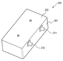
- 3A is a perspective view of a multimode bandpass filter according to a second embodiment of the present invention.
- 3B is a perspective view of a transmission of a multimode bandpass filter according to a second embodiment of the present invention.
- 3C is a graph of characteristic measurement of a multimode bandpass filter according to a second embodiment of the present invention.
- FIG. 4A is a perspective view illustrating transmission of a multimode bandpass filter according to a third embodiment of the present invention.
- 4b is a characteristic simulation graph according to a third embodiment of the present invention.
- FIG. 5 is a perspective view showing transmission of a multimode bandpass filter according to a fourth embodiment of the present invention.
- FIG. 6 is a perspective view illustrating transmission of a multimode bandpass filter according to a fifth embodiment of the present invention.
- FIG. 7 is a perspective view illustrating transmission of a multimode bandpass filter according to a sixth exemplary embodiment of the present invention.
- FIG. 8 is a perspective view illustrating transmission of a multimode bandpass filter according to a seventh exemplary embodiment of the present invention.
- 9A and 9B are graphs of a characteristic measurement of a multimode bandpass filter according to an aspect of the present invention.
- FIG 2a is a perspective view of a multi-mode bandpass filter according to a first embodiment of the present invention
- Figure 2b is a transmission perspective view of the first embodiment, the illustration of the cover is omitted.
- the multimode bandpass filter 200 according to the first embodiment of the present invention includes a housing 201 and a cover 202 for shielding a cavity.
- the housing 201 and the cover 202 are made of metal to shield the internal signal, and sometimes used by plating a non-conductor such as plastic.
- It also has input / output ports 210 and 211 for inputting and outputting signals that will generate resonance in the cavity.
- FIG. 2B which is a transmission perspective view of FIG. 2A
- the two transmission lines 220 and 221 serve to couple the energy required by the dielectric resonator element to achieve the desired filter.
- the two transmission lines 220 and 221 may be electrically shorted or opened with the housing 201 and the desired energy coupling. The amount can be implemented by the distance between the transmission line and the dielectric resonant element, the length, thickness and shape of the transmission line.
- each frequency resonant mode for implementing the multi-mode bandpass filter 200 generally occurs in relation to the ratio of diameter and length of the dielectric resonator 230. . Therefore, by adjusting the ratio of diameter and length, each resonance mode can be resonated at the same frequency.
- the dielectric resonance device 230 is manufactured in a donut shape to triple-resonate as described in claim 8 of the present invention to facilitate the manufacture of the dielectric resonance device 230 and the dielectric resonance device 230. It is to facilitate the heat dissipation generated in.
- the dielectric resonance device 230 is similar to the cylindrical shape, for example, through-holes are formed in the longitudinal direction in the center thereof. Also, as described in US Pat. No. 4,675,630, the dielectric resonance as described in claim 1 is not provided with the screws 16, 18 20 of FIG. 1 for energy coupling between different frequency resonant modes of different multimode band resonant filters.
- a dielectric resonator device 230 having a partly modified shape of the device 230 is provided. In the first embodiment, energy donor coupling is performed between multiple resonances by applying a shape deformation to a donut shape, but the present invention may be applied to a cylinder and a square model.
- the dielectric resonator 230 used in this case generally uses a high dielectric constant compared to the supporter 240, is provided as a dielectric having a low loss tangent coefficient, and has a low loss tangent, so that a high selectivity (Q) is generated in the filter. To reduce the loss.
- the dielectric resonator element 230 may not be located at the center of the cavity, but is generally positioned at the center of the cavity to obtain the best quality factor (Q).
- a support 240 having a low dielectric constant and a low loss tangent coefficient is provided.
- the supporter 240 is in contact with the dielectric resonant element, and the opposite side thereof is in contact with the housing 201.
- the support uses alumina (Al 2 O 3 ) because it has a low loss tangent coefficient and is excellent in thermal conductivity, so that heat generated in the dielectric resonant element can be removed to the housing 201.
- Teflon, plastic, and the like can also be used.
- the resonance adjustment screw 250 may be provided for fine resonance frequency adjustment.
- FIG. 2C is a characteristic measurement graph for the multi-mode bandpass filter 200 provided as shown in FIGS. 2A and 2B according to the first embodiment of the present invention. As shown in Figure 2c, the multi-mode bandpass filter 200 according to the present invention can be seen that a number of modes occur.
- a portion of the donut-type dielectric resonator element 230 is modified to generate multiple resonances.
- the modified structure is a planar structure of the dielectric resonator element 230. It can be seen that the portion is removed from the structure (that is, the structure cut out a portion from the circle in the example of Figures 2a, 2b). The larger the amount of variation (circle cut), the higher the bandwidth of the filter, and the more the half-circle can be cut off. Such modified amount may be appropriately designed in consideration of the filtering characteristics of the desired filter.
- the first and second transmission lines 220 and 221 (and thus the input / output port) shown in FIG. 2B are configured to be positioned at 90 degrees with respect to the dielectric resonator element 230 at a plane.
- This arrangement is the main configuration for causing two or more resonances in one cavity.
- the deformed portion of the dielectric resonator element 230 is preferably formed in the quadrant of the side opposite to the quadrant between the first and second transmission lines 220, 221 which are positioned at 90 degrees to each other on the plane. .
- FIG. 3A is a perspective view of a bandpass filter according to a second embodiment of the present invention
- FIG. 3B is a perspective view of a transmission in the second embodiment.
- the second embodiment of the present invention implements the multimode bandpass filter 300 by extending the multiple resonances of one cavity into two cavities as in the first embodiment of the present invention described above.
- two cavities are described for convenience of understanding, but in actual use, the two cavities may be applied to all two or more cavities.
- the multimode bandpass filter 300 includes a housing 301 and a cover 302.
- the material and the use of the housing and the cover are the same as those of the housing 201 and the cover 202 of the first embodiment.
- the multi-mode bandpass filter 300 includes input / output ports 310 and 311, first and second transmission lines 320 and 321, and the materials and uses thereof are the input / output ports of the first embodiment ( 210 and 211 and the first and second transmission lines 220 and 221, respectively.
- the dielectric well-known elements 330 and 331, the support bodies 340 and 341, and the resonance adjusting screws 350 and 251 are provided to determine the first embodiment into two cavities.
- the dielectric known elements 230, the supporter 240, and the resonance adjusting screw 250 of the embodiment are the same.
- the third and fourth transmission lines 360 and 361 serve to couple energy required by the dielectric resonator elements 330 and 331 to implement the filter
- the fifth transmission line 362 is the third The fourth transmission line 360 and 361 are connected to each other.
- the third and fourth transmission lines 360 and 361 may be electrically shorted or opened with the housing 301 in the same manner as the first and second transmission lines in some cases, and the amount of energy coupling desired is determined by the transmission line and the dielectric resonance.
- the distance between the elements, the length of the transmission line, the thickness, and the shape may be implemented.
- FIG. 3C a characteristic measurement state of the multi-mode bandpass filter 300 provided as shown in FIGS. 3A and 3B is shown.
- FIGS. 4A to 8 a cover is schematically illustrated for convenience of explanation, and the role thereof is also the same and excluded from the description. It was.
- FIG. 4A is a perspective view illustrating transmission of a bandpass filter according to a third embodiment of the present invention.
- the multimode bandpass filter 400 includes a housing 401 and a cover for shielding a cavity.
- the material and the use of the housing 401 and the cover are the same as those of the housing 201 and the cover 202 of the first embodiment.
- the shape of the dielectric resonant element is partially modified in order to energy couple between the frequency resonant modes.
- the phenomenon of the housing 401 is partially modified to couple energy between multiple resonances. It was possible to ring.
- the multi-mode bandpass filter 400 includes input / output ports 410 and 411, first and second transmission lines 420 and 421, a support 440, and a resonance adjusting screw 450.
- the purpose of use is the same as the input / output ports 210 and 211, the first and second transmission lines 220 and 221, the supporter 240, and the resonance adjusting screw 250 of the first embodiment.
- the dielectric known element 430 since the dielectric known element 430 partially forms a shape of the housing 401 to form an energy coupling, the dielectric known element 430 is provided in a general donut shape (ie, an undeformed structure).
- FIG. 4B is a characteristic simulation graph of the multi-mode bandpass filter 200 provided in FIG. 4A according to the third embodiment of the present invention. As shown in Figure 4b, it can be seen that the multimode bandpass filter 200 according to the present invention generates a plurality of modes.
- the internal structure of the housing 401 is a structure in which a portion is further added to the dielectric resonating element 430 (that is, a structure in which one corner portion is partially filled in the planar quadrangular internal structure in the example of FIG. 4A). have.
- the amount of deformation the amount filled in the corners
- the bandwidth of the filter may be increased, and the amount of deformation may be appropriately designed in consideration of filtering characteristics of a desired filter.
- the first and second transmission lines 420 and 421 (and thus the input / output ports) shown in FIG. 4A are configured to be positioned at 90 degrees to each other with respect to the dielectric resonator element 230 in plan view.
- the deformed portion of the housing 401 is preferably formed in a quadrant of the side opposite to the quadrant between the first and second transmission lines 420 and 421 positioned at 90 degrees to each other on the plane.
- FIG. 5 is a perspective view of a bandpass filter according to a fourth embodiment of the present invention, and the fourth embodiment of the present invention is the same as the third embodiment of the present invention described above.
- the multimode bandpass filter 500 is implemented by expanding to.
- two cavities are described for the sake of understanding, but in actual use, the two cavities may also be applied to all two or more cavities.
- the multimode bandpass filter 500 includes a housing 501 and a cover.
- the material and the use of the housing and the cover are the same as those of the housing 201 and the cover 202 of the first embodiment.
- the multi-mode bandpass filter 500 includes input / output ports 510 and 511 and first and second transmission lines 520 and 521. 210 and 211 and the first and second transmission lines 220 and 221, respectively.
- the dielectric well-known elements 530 and 531, the support bodies 540 and 541, and the resonance adjusting screws 550 and 551 are provided to determine the third embodiment into two cavities.
- the dielectric well-known element 430, the support 440, and the resonance adjusting screw 450 of the embodiment are the same.
- the multimode bandpass filter 500 also includes third, fourth, and fifth transmission lines 560, 561, 562.
- the material used and the use thereof are the same as those of the third, fourth, and fifth transmission lines 360, 361, and 362 of the second embodiment.
- FIG. 6 is a perspective view showing a transmission band of the bandpass filter according to the fifth embodiment of the present invention, the fifth embodiment of the present invention is implemented by applying the first and third embodiments described above to one cavity. That is, in order to energy couple between multiple resonant modes in one cavity, the shape of the dielectric resonator element 630 and the housing 601 may be partially modified together to implement the multi-mode bandpass filter 600.
- the input / output ports 610 and 611, the first and second transmission lines 620 and 621, and the support 640 are similar to the previous embodiments.
- the resonance adjusting screw 650 may be provided.
- FIG. 7 is a perspective view of a bandpass filter according to a sixth embodiment of the present invention, and the sixth embodiment of the present invention has two cavities having multiple resonances in one cavity as in the fifth embodiment of the present invention described above.
- the multimode bandpass filter 700 is implemented by extending to.
- two cavities are described for the sake of understanding, but in actual use, the two cavities may be applied to all two or more cavities.
- the housing 701, the input / output ports 710 and 711, the first and second transmission lines 720 and 721 and the dielectric resonator 730 are similar to those of the previous embodiments. 731, supports 740 and 741.
- the resonance adjusting screws 750 and 751 and the third, fourth and fifth transmission lines 760, 761 and 762 may be provided.
- FIG. 8 is a perspective view of a bandpass filter according to a seventh embodiment of the present invention, and the seventh embodiment of the present invention implements the first and third embodiments described above in each cavity.
- the multiple resonance mode is implemented in. That is, the dielectric resonating element is modified in one or more cavities, and the shape of the cavity is modified in the other one or more cavities to implement the multimode bandpass filter 800.
- the housing 801, the input / output ports 810 and 811, the first and second transmission lines 820 and 821, and the dielectric resonator 830 are the same as in the previous embodiments. 831), supports 840 and 841.
- the resonance adjusting screws 850 and 851 and the third, fourth and fifth transmission lines 860, 861 and 862 may be provided.
- FIG. 9A and 9B are graphs of a characteristic measurement comparison of a multi-mode bandpass filter according to a feature of the present invention.
- FIG. 9A shows a characteristic measurement result when there is no through hole in a center portion of a dielectric resonant element.
- the through hole is formed in the center portion of the dielectric resonator device.
- spurious occurs at a frequency higher than the use frequency compared with the structure without forming the through holes.
- a multi-mode band pass filter according to embodiments of the present invention may be configured, and other embodiments may be implemented in various modifications and variations of the present invention.
- the structure of the multimode bandpass filter having one cavity or having two cavities as illustrated in FIG. 5 is described.
- a structure having three or more cavities may be similarly employed.
- FIG. 5 and the like a structure in which a plurality of (for example, two) cavities are used to couple each other using third to fifth transmission lines has been described.
Landscapes
- Control Of Motors That Do Not Use Commutators (AREA)
Priority Applications (2)
| Application Number | Priority Date | Filing Date | Title |
|---|---|---|---|
| JP2014551194A JP2015506628A (ja) | 2012-01-05 | 2013-01-07 | マルチモード帯域通過フィルタ |
| US14/324,800 US20140320239A1 (en) | 2012-01-05 | 2014-07-07 | Multi-mode bandpass filter |
Applications Claiming Priority (2)
| Application Number | Priority Date | Filing Date | Title |
|---|---|---|---|
| KR20120001631 | 2012-01-05 | ||
| KR10-2012-0001631 | 2012-01-05 |
Related Child Applications (1)
| Application Number | Title | Priority Date | Filing Date |
|---|---|---|---|
| US14/324,800 Continuation US20140320239A1 (en) | 2012-01-05 | 2014-07-07 | Multi-mode bandpass filter |
Publications (1)
| Publication Number | Publication Date |
|---|---|
| WO2013103269A1 true WO2013103269A1 (fr) | 2013-07-11 |
Family
ID=48745296
Family Applications (1)
| Application Number | Title | Priority Date | Filing Date |
|---|---|---|---|
| PCT/KR2013/000075 Ceased WO2013103269A1 (fr) | 2012-01-05 | 2013-01-07 | Filtre passe-bande multi-mode |
Country Status (4)
| Country | Link |
|---|---|
| US (1) | US20140320239A1 (fr) |
| JP (1) | JP2015506628A (fr) |
| KR (1) | KR20130080821A (fr) |
| WO (1) | WO2013103269A1 (fr) |
Cited By (3)
| Publication number | Priority date | Publication date | Assignee | Title |
|---|---|---|---|---|
| CN104659445A (zh) * | 2015-01-21 | 2015-05-27 | 江苏贝孚德通讯科技股份有限公司 | 一种带通滤波器 |
| WO2016063997A1 (fr) * | 2014-10-21 | 2016-04-28 | 주식회사 케이엠더블유 | Resonateur multimode |
| GB2531973A (en) * | 2013-09-06 | 2016-05-04 | Procter & Gamble | Pouches comprising water-soluble fibrous wall materials and methods for making same |
Families Citing this family (5)
| Publication number | Priority date | Publication date | Assignee | Title |
|---|---|---|---|---|
| CN106910969A (zh) * | 2017-04-25 | 2017-06-30 | 四川省韬光通信有限公司 | 一种介质波导耦合结构及多阶介质波导滤波器 |
| KR101897625B1 (ko) * | 2017-09-01 | 2018-09-12 | 주식회사 에이스테크놀로지 | 삼중모드 유전체 공진기와 nrn 스터브를 이용한 대역통과필터 |
| US10727556B2 (en) | 2018-02-13 | 2020-07-28 | Electronics And Telecommunications Research Institute | Multimode microwave filter |
| KR101987344B1 (ko) | 2019-03-20 | 2019-06-10 | 이재복 | 대역 조절수단이 구비된 다중대역통과필터 |
| CN111816972B (zh) * | 2020-08-07 | 2022-03-15 | 物广系统有限公司 | 一种高q多模介质谐振结构和介质滤波器 |
Citations (4)
| Publication number | Priority date | Publication date | Assignee | Title |
|---|---|---|---|---|
| US4652843A (en) * | 1984-05-28 | 1987-03-24 | Com Dev Ltd. | Planar dual-mode cavity filters including dielectric resonators |
| US5994981A (en) * | 1995-03-08 | 1999-11-30 | Murata Manufacturing Co., Ltd. | Dielectric filter having obliquely oriented stepped resonators |
| US6873222B2 (en) * | 2000-12-11 | 2005-03-29 | Com Dev Ltd. | Modified conductor loaded cavity resonator with improved spurious performance |
| KR20090109445A (ko) * | 2008-04-15 | 2009-10-20 | (주)에어링크테크놀로지 | 원반형 홈을 갖는 원통형 유전체 공진기 및 그를 이용한다중 모드 대역통과 필터 |
Family Cites Families (3)
| Publication number | Priority date | Publication date | Assignee | Title |
|---|---|---|---|---|
| US6707353B1 (en) * | 1999-11-02 | 2004-03-16 | Matsushita Electric Industrial Co., Ltd. | Dielectric filter |
| US6650208B2 (en) * | 2001-06-07 | 2003-11-18 | Remec Oy | Dual-mode resonator |
| GB2465522B (en) * | 2007-09-19 | 2012-02-15 | Ngk Spark Plug Co | Dielectric resonator, dielectric resonator filter and method for controlling dielectric resonator |
-
2013
- 2013-01-07 JP JP2014551194A patent/JP2015506628A/ja active Pending
- 2013-01-07 KR KR1020130001513A patent/KR20130080821A/ko not_active Withdrawn
- 2013-01-07 WO PCT/KR2013/000075 patent/WO2013103269A1/fr not_active Ceased
-
2014
- 2014-07-07 US US14/324,800 patent/US20140320239A1/en not_active Abandoned
Patent Citations (4)
| Publication number | Priority date | Publication date | Assignee | Title |
|---|---|---|---|---|
| US4652843A (en) * | 1984-05-28 | 1987-03-24 | Com Dev Ltd. | Planar dual-mode cavity filters including dielectric resonators |
| US5994981A (en) * | 1995-03-08 | 1999-11-30 | Murata Manufacturing Co., Ltd. | Dielectric filter having obliquely oriented stepped resonators |
| US6873222B2 (en) * | 2000-12-11 | 2005-03-29 | Com Dev Ltd. | Modified conductor loaded cavity resonator with improved spurious performance |
| KR20090109445A (ko) * | 2008-04-15 | 2009-10-20 | (주)에어링크테크놀로지 | 원반형 홈을 갖는 원통형 유전체 공진기 및 그를 이용한다중 모드 대역통과 필터 |
Non-Patent Citations (1)
| Title |
|---|
| RAAFAT R. MANSOUR: "Novel configurations for dielectric loaded and conductor loaded cavity resonators with improved spurious performance.", PROCEEDINGS OF 2001 ASIA- PACIFIC MICROWAVE CONFERENCE (APMC 2001), vol. 2, 2001, TAIPEI, TAIWAN, pages 741 - 746, XP010578642 * |
Cited By (7)
| Publication number | Priority date | Publication date | Assignee | Title |
|---|---|---|---|---|
| GB2531973A (en) * | 2013-09-06 | 2016-05-04 | Procter & Gamble | Pouches comprising water-soluble fibrous wall materials and methods for making same |
| GB2531973B (en) * | 2013-09-06 | 2018-12-26 | Procter & Gamble | Pouches comprising water-soluble fibrous wall materials and methods for making same |
| WO2016063997A1 (fr) * | 2014-10-21 | 2016-04-28 | 주식회사 케이엠더블유 | Resonateur multimode |
| US10109906B2 (en) | 2014-10-21 | 2018-10-23 | Kmw Inc. | Multimode resonator |
| US10601101B2 (en) | 2014-10-21 | 2020-03-24 | Kmw Inc. | Multimode resonator |
| US10847861B2 (en) | 2014-10-21 | 2020-11-24 | Kmw Inc. | Multimode resonator |
| CN104659445A (zh) * | 2015-01-21 | 2015-05-27 | 江苏贝孚德通讯科技股份有限公司 | 一种带通滤波器 |
Also Published As
| Publication number | Publication date |
|---|---|
| JP2015506628A (ja) | 2015-03-02 |
| US20140320239A1 (en) | 2014-10-30 |
| KR20130080821A (ko) | 2013-07-15 |
Similar Documents
| Publication | Publication Date | Title |
|---|---|---|
| WO2013103269A1 (fr) | Filtre passe-bande multi-mode | |
| US4453146A (en) | Dual-mode dielectric loaded cavity filter with nonadjacent mode couplings | |
| EP3235054B1 (fr) | Filtre en ligne avec couplage capacitif et inductif à compensation mutuelle | |
| US9190705B2 (en) | Dual mode dielectric resonator filter having plural holes formed therein for receiving tuning and coupling screws | |
| CN108475836B (zh) | 一种滤波器及无线网络设备 | |
| US6356171B2 (en) | Planar general response dual-mode cavity filter | |
| WO2017095035A1 (fr) | Filtre de fréquence sans fil du type à cavité, possédant une structure à encoche de couplage croisé | |
| CN105006617B (zh) | 三模介质腔体滤波器 | |
| JPH08330806A (ja) | 誘電体フィルタおよびアンテナ共用器 | |
| WO2009157672A2 (fr) | Procédé de fabrication de résonateur pour un filtre rf et filtre rf doté d'un tel résonateur | |
| WO2021182668A1 (fr) | Filtre à cavité haute fréquence et dispositif de communication le comprenant | |
| US5557246A (en) | Half wavelengh and quarter wavelength dielectric resonators coupled through side surfaces | |
| JPS581301A (ja) | 導波管型誘電体フィルタ | |
| CN107251314A (zh) | 腔体滤波器及具有该腔体滤波器的射频拉远设备、信号收发装置和塔顶放大器 | |
| CN210129570U (zh) | 介质波导滤波器 | |
| WO2023005651A1 (fr) | Filtre diélectrique multimode | |
| CN105789792A (zh) | 一种单腔多模的金属圆柱腔滤波器 | |
| WO2013129817A1 (fr) | Filtre de fréquence radio ayant une structure de cavité | |
| JP2004349981A (ja) | 共振器装置、フィルタ、複合フィルタ装置および通信装置 | |
| CN222785445U (zh) | 一种滤波器 | |
| US5798676A (en) | Dual-mode dielectric resonator bandstop filter | |
| CN219513314U (zh) | 一种瓦片式功分器 | |
| WO2023282372A1 (fr) | Filtre passe-haut coaxial et dispositif de communication le comprenant | |
| JPS6192001A (ja) | 高周波電気回路網 | |
| CN115051133B (zh) | 波导宽边宽带耦合电桥 |
Legal Events
| Date | Code | Title | Description |
|---|---|---|---|
| 121 | Ep: the epo has been informed by wipo that ep was designated in this application |
Ref document number: 13733762 Country of ref document: EP Kind code of ref document: A1 |
|
| ENP | Entry into the national phase |
Ref document number: 2014551194 Country of ref document: JP Kind code of ref document: A |
|
| NENP | Non-entry into the national phase |
Ref country code: DE |
|
| 122 | Ep: pct application non-entry in european phase |
Ref document number: 13733762 Country of ref document: EP Kind code of ref document: A1 |