WO2013104780A1 - Support d'ustensile - Google Patents
Support d'ustensile Download PDFInfo
- Publication number
- WO2013104780A1 WO2013104780A1 PCT/EP2013/050526 EP2013050526W WO2013104780A1 WO 2013104780 A1 WO2013104780 A1 WO 2013104780A1 EP 2013050526 W EP2013050526 W EP 2013050526W WO 2013104780 A1 WO2013104780 A1 WO 2013104780A1
- Authority
- WO
- WIPO (PCT)
- Prior art keywords
- utensil
- utensil holder
- holder
- manufactured
- main body
- Prior art date
- Legal status (The legal status is an assumption and is not a legal conclusion. Google has not performed a legal analysis and makes no representation as to the accuracy of the status listed.)
- Ceased
Links
Images


Classifications
-
- B—PERFORMING OPERATIONS; TRANSPORTING
- B44—DECORATIVE ARTS
- B44D—PAINTING OR ARTISTIC DRAWING, NOT OTHERWISE PROVIDED FOR; PRESERVING PAINTINGS; SURFACE TREATMENT TO OBTAIN SPECIAL ARTISTIC SURFACE EFFECTS OR FINISHES
- B44D3/00—Accessories or implements for use in connection with painting or artistic drawing, not otherwise provided for; Methods or devices for colour determination, selection, or synthesis, e.g. use of colour tables
- B44D3/12—Paint cans; Brush holders; Containers for storing residual paint
- B44D3/123—Brush holders independent from paint can, e.g. holders removably attached to paint can
-
- A—HUMAN NECESSITIES
- A47—FURNITURE; DOMESTIC ARTICLES OR APPLIANCES; COFFEE MILLS; SPICE MILLS; SUCTION CLEANERS IN GENERAL
- A47J—KITCHEN EQUIPMENT; COFFEE MILLS; SPICE MILLS; APPARATUS FOR MAKING BEVERAGES
- A47J43/00—Implements for preparing or holding food, not provided for in other groups of this subclass
- A47J43/28—Other culinary hand implements, e.g. spatulas, pincers, forks or like food holders, ladles, skimming ladles, cooking spoons; Spoon-holders attached to cooking pots
- A47J43/287—Holders for spoons or the like attached to cooking pots
-
- A—HUMAN NECESSITIES
- A46—BRUSHWARE
- A46B—BRUSHES
- A46B17/00—Accessories for brushes
- A46B17/02—Devices for holding brushes in use
-
- A—HUMAN NECESSITIES
- A46—BRUSHWARE
- A46B—BRUSHES
- A46B2200/00—Brushes characterized by their functions, uses or applications
- A46B2200/20—Brushes for applying products to surfaces in general
- A46B2200/202—Applicator paint brush
Definitions
- the present invention relates to a utensil holder for supporting a utensil.
- the working head is required to be kept clear of surfaces for hygienic reasons and as such the cook is left with the task of balancing these cooking implements on the rims of pots, pans or adjacent containers so that the same utensil can be safely used repeatedly as the produce cooks.
- the present invention provides a utensil holder having means for releasably retaining a part of a utensil and releasable engagement means being removably attachable to the edge of a surface and being mountable onto a surface, the utensil holder being capable of supporting a received utensil so that the working head of the utensil is kept away from a surface, the utensil holder being capable of using the weight of the utensil to reinforce its hold on the edge of the surface and on the surface, the utensil holder being sufficiently small and lightweight to be retainable on the utensil during use without impairing the functionality of the utensil.
- the utensil holder being adapted to support a received utensil so that the working head of the utensil is kept away from a surface.
- the utensil holder being adapted to use the weight of the utensil to reinforce its hold on the edge of the surface and on the surface.
- the surface is a surface on which the utensil holder is mounted and/or a base surface of a container on which the utensil holder is mounted.
- the present invention is technically simpler than the prior art utensil holders because of the removal of the complexity associated with the clip/grip features and the utensil engaging portion envisaged in the prior art. Furthermore, compared to the prior art, the invention does not interfere in the work process because the holder remains attached to the utensil during its use, saving time and effort of a user for attaching/detaching the utensil.
- the invention also makes it easy to locate a utensil and prevents it from rolling off a work surface. It can, advantageously, keep an artist’s paintbrush immersed in a liquid during a work session. At the end of the work session, a painting/cooking implement can be hung in a position so as to prevent it from being distorted/deformed due to its contact with a solid surface or a liquid.
- the releasable engagement means is provided on a portion of the utensil holder distal the means for releasably retaining a part of the utensil.
- the utensil holder comprises a generally U-shaped main body.
- the generally U-shaped main body has two legs, preferably similar.
- the releasable engagement means is located at the base of the two legs.
- the releasable engagement means comprises a hook portion proximal to the free end of each leg.
- the hook allows the utensil holder to rest/fit over the edge of a surface in a first mode of operation.
- the releasable engagement means comprises a support foot on the free end of each leg.
- the support feet enable the utensil holder to maintain a strong grip on the surface when the utensil holder is loaded with a utensil in a second mode of operation.
- the soles of the support feet are flat.
- the flat soles help in holding the utensil in a stable manner.
- each support foot is provided with gripping means such as notches at one end.
- the gripping means reinforces the frictional contact when a kitchen utensil is supported on a worktop of a kitchen or similar surface.
- the means for releasably retaining a part of a utensil is provided by the main body of the utensil defining an opening.
- a slit extends from outside the main body of the utensil holder through a wall of the main body of the utensil holder into the opening.
- the slit means that the opening size is flexible allowing it to receive utensils of various shapes and sizes.
- the utensil holder is designed to have at least one opening to receive a utensil.
- the utensil holder is designed to have more than one opening to receive one or more utensils.
- the means for releasably retaining a part of the utensil is a magnetic/metallic catch on the utensil holder capable of operating in conjunction with a metallic/magnetic portion on the handle of the utensil.
- the utensil holder is provided with at least one leg/releasable engagement means attachable to the edge of a surface and mountable onto a surface.
- the utensil holder is provided with more than one leg/releasable engagement means attachable to the edge of a surface and mountable onto a surface.
- the utensil holder is capable of holding an artist’s paintbrush.
- the utensil holder is capable of holding/supporting kitchen utensils/implements.
- the utensil holder is manufactured as a single homogeneous piece.
- the utensil holder is manufactured from non-metallic material.
- the utensil holder is manufactured from an elastomeric material.
- the utensil holder is manufactured from a silicone elastomer.
- the utensil holder is manufactured from a food grade silicone elastomer.
- the manufacturing material for the utensil holder is a non-conductor of heat.
- the material the device is manufactured from is resistant to degradation at temperatures greater than -30 Degrees Celsius.
- the material the utensil holder is manufactured from is resistant to degradation at temperatures greater than -20 Degrees Celsius.
- the material the utensil holder is manufactured from is resistant to degradation at temperatures less than 600 Degrees Celsius.
- the material the utensil holder is manufactured from is resistant to degradation at temperatures less than 500 Degrees Celsius.
- the utensil holder is coated with an unpleasant tasting additive.
- this additive coating is added to reduce the risk of a child mistaking the utensil holder for a sweet.
- the additive coating is dispersed throughout the material of the utensil holder.
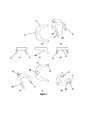
- Figure 1 is a perspective view of a utensil holder in accordance with the invention.
- Figure 2 (a) is an underside plan view of a utensil holder shown in Figure 1;
- Figure 2 (b) is a second perspective view of utensil holder
- Figure 2 (c) is a front elevational view of utensil holder
- Figure 2 (d) is a side view of utensil holder
- Figure 2 (e) is a rear elevational view of utensil holder
- Figure 2 (f) is a third perspective view of utensil holder
- Figure 2 (g) is a top plan view of utensil holder
- Figure 2 (h) is a fourth perspective view of utensil holder
- Figure 3 shows the first mode of operation of the utensil holder
- Figure 4 shows the second mode of operation of the utensil holder
- Figure 5 is an end elevation view of the utensil holder acting as a stop for bottles.
- Figure 6 is an side view of the utensil holder acting as an individual rack for a bottle
- a utensil holder indicated generally by the reference numeral 1 for holding a utensil 8 (see Figures 3 and 4) being a spoon 8 for stirring food as it cooks.
- the utensil holder 1 has an arrangement 2 for releasably retaining a part of the utensil 8 (see Figures 1 and 2).
- a portion of the utensil holder 1, distal the arrangement 2 for releasably retaining a part of the utensil 8, has releasable engagement members 3 being removably attachable to the edge 9 of a surface see especially Figure 3 and on top of a surface or onto a surface, see especially Figures 4 5 or 6.
- the utensil holder 1 In the second mode of operation shown in Figure 4, the utensil holder 1 is inverted when compared to its use in the first mode of operation shown in Figure 3.
- the utensil holder 1 supports a received utensil 8 so that the tip only of the utensil 8 rests against the internal surface of the pot 24 of Figure 3 or the head of the utensil is kept off the work surface of Figure 4.
- the utensil holder 1 uses the weight of the utensil 8 to reinforce its hold on the edge 9 of the surface of the pot 24 or on the surface.
- the utensil holder 1 is sufficiently small and light so as to enable it to remain on the utensil 8 during use without impairing the functionality of the utensil 8.
- the utensil holder 1 is technically simpler than the prior art utensil holders because of the removal of the complexity associated with the clip/grip features and the utensil engaging portion envisaged in the prior art. Furthermore, compared to the prior art, the utensil holder 1 does not interfere in the work process because the utensil holder 1 remains attached to the utensil 8 during its use. This saves time and effort for a user omitting the requirement for attaching/detaching the utensil 8.
- the utensil holder 1 makes it easy to locate the utensil 8, preventing the head of the utensil 8 from coming into contact with a potentially unhygienic work surface and keeping the utensil 8 located close to where it is required by the user.
- An additional use of the utensil holder 1 in this first mode of operation is for retaining a paint brush on the edge of a paint pot in a position so that the bristles of the head of the paint brush are kept away from the base of the paint pot therefore eliminating deformation of the bristles when the brush is left hanging in the pot/jar.
- the paint brush can be left mounted on the utensil holder 1 with the head suspended out of the paint and away from the bottom surface. Suspending the paintbrush in this way prevents distortion due to the head of the paint brush resting on the bottom of the pot.
- the working head 10 of a cooking implement/spoon 8 is kept clear of surfaces for hygienic reasons and as such the cook is not left with the task of balancing the cooking implement/spoon 8 on the rims of pots, pans or adjacent containers/surfaces so that it can be safely used repeatedly as the produce cooks.
- the utensil holder 1 comprises a generally U-shaped main body 21.
- the U-shaped main body 21 has two similar legs 4.
- the releasable engagement members 3 are located at the base of the two legs 4.
- the releasable engagement members 3 provide a hook portion 22 proximal to the free end of each leg 4. This hook portion 22 allows the utensil holder 1 to rest/fit over the edge 9 of a surface in the inverted position as shown in Figure 3.
- a support foot 5 is provided on the free end of each leg 4 as shown in Figures 1 and 2. It enables the utensil holder 1 to maintain a strong grip on the surface when the utensil holder 1 is loaded with a utensil 8 as shown in Figure 4.
- the soles of the support feet 5 are flat, see especially Figures 1, 2(b), 2(f) and 2(h). In Figures 2a and 2g, it is shown that that the feet 5 curve outwards. Advantageously, this helps a user grab and pinch the utensil holder 1 easier with their forefinger and thumb.
- the flat nature of the soles of the feet 5 helps in holding the utensil 8 in a stable manner as shown in Figure 4.
- the geometry of the main body 21 and the feet 5 of the utensil holder can be designed so that the utensil holder 1 can stand upright on the soles of the feet 5 unaided.
- the feet 5 have toes which increase the surface area therefore allowing more heat to dissipate.
- the sole of each support foot 5 has gripping members provided by notches 7 at one end, which reinforces the frictional contact when a cooking utensil 8 is supported on the worktop of the kitchen as shown in Figure 4.
- the integrally formed product logo protrudes on both top and bottom of the utensil holder acting as anti-slip means which increases the grip of the utensil holder reducing the risk of movement, particularly when holding bottles 51.
- the end of the handle of the utensil 8 and the two legs 4 of the utensil holder 1 act as a tripod to retain the working head 10 of the spoon 8 away from potentially unhygienic surfaces.
- the arrangement 2 for releasably retaining a part of a utensil 8 is provided by the main body 21 having an opening 25 formed for receiving a part of a handle of the utensil 8.
- a slit 6 extends from outside the main body 21 of the utensil holder 1 through the wall of the main body 21 enclosing the opening 25 and into the opening 25. This makes the opening 25 flexible enough to allow it to receive utensils 8 of various shapes and sizes.
- the slit 6 and opening 25 allows an operator to use the utensil holder 1 as a clip to keep bagged foodstuff fresh by clipping the bagged closed.
- the arrangement 2 for releasably retaining a part of the utensil is a magnetic/metallic catch 41 on the utensil holder 1 operating in conjunction with a metallic/magnetic portion 42 on the handle of the utensil 8.
- the utensil holder 1 can be placed with the main body 21 resting substantially flat on a surface and the releasable engagement members 3 protruding upwards away from the surface.
- the two upwardly protruding releasable engagement members 3 in combination with the U-shaped main body 21 defines an arrangement for preventing products such as bottle 51 from rolling or rotating away from the position of the surface on which they are located.
- the utensil holder 1 in this orientation is capable of securing any product which is resting on a non flat support surface from rolling or rotating away from the position of the surface on which they are located.
- utensil holder 1 can be placed in boiling water on the base of a pot or pan along with an egg in order to stop the egg bumping into the pan and into other eggs, preventing cracking of the one or more eggs.
- the utensil holder 1 can be placed with the main body 21 resting slightly above a surface with the releasable engagement members 3 protruding towards and contacting the surface. In this orientation, the utensil holder can act as a stop for a number of bottles 51 rolling along the surface such as a shelf of a fridge as shown in Figure 5.
- the two downwardly protruding releasable engagement members 3 in combination with the U-shaped main body 21 defines an arrangement for supporting products a short distance off the surface on which they are required to be temporarily located. This is useful to prevent ladles, rolling pins or other cooking accessories from coming into contact with work surfaces for example.
- the utensil holder 1 is ideal to be used on a boat or a campervan to stop 'items' rolling about.
- the utensil holder 1 is a non-metallic homogenous piece.
- the utensil holder 1 is manufactured from a material which has low thermal conductivity and is heat resistant to a temperature of -30 degrees to 600 degrees Celsius making it possible to use it on a cooking pan, near a cooking surface or in an oven.
- the utensil holder 1 is coated with an unpleasant tasting additive.
- this additive coating is added to reduce the risk of a child mistaking the utensil holder for a sweet.
- the additive coating can be dispersed throughout the material of the utensil holder 1.
Landscapes
- Engineering & Computer Science (AREA)
- Mechanical Engineering (AREA)
- Food Science & Technology (AREA)
- Devices For Warming Or Keeping Food Or Tableware Hot (AREA)
Applications Claiming Priority (2)
| Application Number | Priority Date | Filing Date | Title |
|---|---|---|---|
| GB1200367.9 | 2012-01-11 | ||
| GB201200367A GB201200367D0 (en) | 2012-01-11 | 2012-01-11 | A utensil holder |
Publications (1)
| Publication Number | Publication Date |
|---|---|
| WO2013104780A1 true WO2013104780A1 (fr) | 2013-07-18 |
Family
ID=45788725
Family Applications (1)
| Application Number | Title | Priority Date | Filing Date |
|---|---|---|---|
| PCT/EP2013/050526 Ceased WO2013104780A1 (fr) | 2012-01-11 | 2013-01-11 | Support d'ustensile |
Country Status (2)
| Country | Link |
|---|---|
| GB (1) | GB201200367D0 (fr) |
| WO (1) | WO2013104780A1 (fr) |
Cited By (6)
| Publication number | Priority date | Publication date | Assignee | Title |
|---|---|---|---|---|
| US9427674B2 (en) | 2014-05-29 | 2016-08-30 | Dickson Oi | Clip attachment system |
| AU2015200759A1 (en) * | 2015-02-16 | 2016-09-01 | Digix Pty Limited | Non-Slippage, Non-Scratch & Non-Heat Damage Device |
| WO2017218289A1 (fr) * | 2016-06-13 | 2017-12-21 | Wares World Wide Llc | Dispositif pour fixer des ustensiles à un article à service de table |
| US10376080B1 (en) | 2017-04-28 | 2019-08-13 | Ryan P Newland | Jar with knife sheath under lid |
| US11647853B1 (en) | 2020-08-11 | 2023-05-16 | Ryan P Newland | Ring for holding knife inside jar |
| US12290192B1 (en) | 2024-05-15 | 2025-05-06 | Ryan Newland | Concentric handle for holding knife inside jar |
Citations (5)
| Publication number | Priority date | Publication date | Assignee | Title |
|---|---|---|---|---|
| US568121A (en) * | 1896-09-22 | Shaving-brush holder | ||
| US1643661A (en) * | 1926-03-04 | 1927-09-27 | Thomas W Kendall | Hanger |
| US4121798A (en) * | 1977-06-16 | 1978-10-24 | Schumacher Donavon J | Utensil handle holder |
| US6056253A (en) * | 1998-08-17 | 2000-05-02 | Tripp; Dave L. | Paintbrush holder having length adjustment |
| US20090256033A1 (en) * | 2008-04-09 | 2009-10-15 | Frank Marino | Brush holder |
-
2012
- 2012-01-11 GB GB201200367A patent/GB201200367D0/en not_active Ceased
-
2013
- 2013-01-11 WO PCT/EP2013/050526 patent/WO2013104780A1/fr not_active Ceased
Patent Citations (5)
| Publication number | Priority date | Publication date | Assignee | Title |
|---|---|---|---|---|
| US568121A (en) * | 1896-09-22 | Shaving-brush holder | ||
| US1643661A (en) * | 1926-03-04 | 1927-09-27 | Thomas W Kendall | Hanger |
| US4121798A (en) * | 1977-06-16 | 1978-10-24 | Schumacher Donavon J | Utensil handle holder |
| US6056253A (en) * | 1998-08-17 | 2000-05-02 | Tripp; Dave L. | Paintbrush holder having length adjustment |
| US20090256033A1 (en) * | 2008-04-09 | 2009-10-15 | Frank Marino | Brush holder |
Cited By (7)
| Publication number | Priority date | Publication date | Assignee | Title |
|---|---|---|---|---|
| US9427674B2 (en) | 2014-05-29 | 2016-08-30 | Dickson Oi | Clip attachment system |
| AU2015200759A1 (en) * | 2015-02-16 | 2016-09-01 | Digix Pty Limited | Non-Slippage, Non-Scratch & Non-Heat Damage Device |
| WO2017218289A1 (fr) * | 2016-06-13 | 2017-12-21 | Wares World Wide Llc | Dispositif pour fixer des ustensiles à un article à service de table |
| US11191379B2 (en) | 2016-06-13 | 2021-12-07 | Wares World Wide Llc | Device for securing utensils to serveware |
| US10376080B1 (en) | 2017-04-28 | 2019-08-13 | Ryan P Newland | Jar with knife sheath under lid |
| US11647853B1 (en) | 2020-08-11 | 2023-05-16 | Ryan P Newland | Ring for holding knife inside jar |
| US12290192B1 (en) | 2024-05-15 | 2025-05-06 | Ryan Newland | Concentric handle for holding knife inside jar |
Also Published As
| Publication number | Publication date |
|---|---|
| GB201200367D0 (en) | 2012-02-22 |
Similar Documents
| Publication | Publication Date | Title |
|---|---|---|
| WO2013104780A1 (fr) | Support d'ustensile | |
| US5518211A (en) | Utensil-holder for containers | |
| US20070289981A1 (en) | Cooking utensil with means of resting on pot, pan, skillet or otherwise | |
| EP2976976B1 (fr) | Ustensile de cuisine comprenant un couvercle ayant une poignée avec support d'ustensile | |
| US10165893B2 (en) | Cookware item with spoon receiving recess | |
| US9125514B1 (en) | Cooking vessel with lid and handle device | |
| US20150164268A1 (en) | Combination Lid and Utensil Holder | |
| US20220265086A1 (en) | Apparatus for cooking bacon and the like inside microwave ovens | |
| US10413118B2 (en) | Lid holding and drying device | |
| US20110031361A1 (en) | Utensil holder | |
| US20150265103A1 (en) | Cooking Utensil Holding Device | |
| MX2011006817A (es) | Utencilio para servir que tiene un elemento de levantamiento de cacerola. | |
| CA2489633C (fr) | Dispositif de manutention d'aliment | |
| US20140008315A1 (en) | Holder for cookware and cooking utensils | |
| US20050217494A1 (en) | Handling assembly | |
| CA3027907C (fr) | Bague adaptatrice de caquelon a fondue | |
| US20240148195A1 (en) | Utensil Holding Device | |
| US11191379B2 (en) | Device for securing utensils to serveware | |
| WO2018031907A1 (fr) | Systèmes, procédés et appareil pour transférer une substance entre des conteneurs | |
| KR20250080512A (ko) | 조리도구용 거치 장치 | |
| RU2682307C2 (ru) | Контейнер для кухонной утвари и кухонных принадлежностей | |
| JP2024050367A (ja) | 瓶上部に取り付ける用具保持装置 | |
| US20230337864A1 (en) | Small Paper Dish for Cooking Utensils | |
| JP3252671U (ja) | キッチンツール及び調理器具システム | |
| KR200227852Y1 (ko) | 조리용구 |
Legal Events
| Date | Code | Title | Description |
|---|---|---|---|
| 121 | Ep: the epo has been informed by wipo that ep was designated in this application |
Ref document number: 13703337 Country of ref document: EP Kind code of ref document: A1 |
|
| NENP | Non-entry into the national phase |
Ref country code: DE |
|
| 122 | Ep: pct application non-entry in european phase |
Ref document number: 13703337 Country of ref document: EP Kind code of ref document: A1 |