WO2013105252A1 - Dispositif d'affichage de carte et procédé d'affichage de carte - Google Patents
Dispositif d'affichage de carte et procédé d'affichage de carte Download PDFInfo
- Publication number
- WO2013105252A1 WO2013105252A1 PCT/JP2012/050512 JP2012050512W WO2013105252A1 WO 2013105252 A1 WO2013105252 A1 WO 2013105252A1 JP 2012050512 W JP2012050512 W JP 2012050512W WO 2013105252 A1 WO2013105252 A1 WO 2013105252A1
- Authority
- WO
- WIPO (PCT)
- Prior art keywords
- screen
- drawing screen
- display
- map
- drawing object
- Prior art date
- Legal status (The legal status is an assumption and is not a legal conclusion. Google has not performed a legal analysis and makes no representation as to the accuracy of the status listed.)
- Ceased
Links
Images











Classifications
-
- G—PHYSICS
- G06—COMPUTING OR CALCULATING; COUNTING
- G06F—ELECTRIC DIGITAL DATA PROCESSING
- G06F3/00—Input arrangements for transferring data to be processed into a form capable of being handled by the computer; Output arrangements for transferring data from processing unit to output unit, e.g. interface arrangements
- G06F3/01—Input arrangements or combined input and output arrangements for interaction between user and computer
- G06F3/048—Interaction techniques based on graphical user interfaces [GUI]
- G06F3/0484—Interaction techniques based on graphical user interfaces [GUI] for the control of specific functions or operations, e.g. selecting or manipulating an object, an image or a displayed text element, setting a parameter value or selecting a range
-
- G—PHYSICS
- G01—MEASURING; TESTING
- G01C—MEASURING DISTANCES, LEVELS OR BEARINGS; SURVEYING; NAVIGATION; GYROSCOPIC INSTRUMENTS; PHOTOGRAMMETRY OR VIDEOGRAMMETRY
- G01C21/00—Navigation; Navigational instruments not provided for in groups G01C1/00 - G01C19/00
- G01C21/26—Navigation; Navigational instruments not provided for in groups G01C1/00 - G01C19/00 specially adapted for navigation in a road network
- G01C21/34—Route searching; Route guidance
- G01C21/36—Input/output arrangements for on-board computers
- G01C21/3667—Display of a road map
- G01C21/367—Details, e.g. road map scale, orientation, zooming, illumination, level of detail, scrolling of road map or positioning of current position marker
Definitions
- the present invention relates to a map display device and a map display method, and more particularly to a map display device and a map display method for simultaneously displaying a plurality of information drawing screens on a display surface.
- map drawing screen is a screen on which drawing objects related to map display are drawn. Drawing objects include road lines, characters, terrain, buildings, icons, background colors (including transparent or translucent), attached information, etc.
- the display surface is the display that actually displays the map drawing screen. It is.
- the map drawing screen is displayed in a predetermined display area on the display surface.
- a map drawing screen related to route guidance is displayed in one display area, and a map drawing screen related to route guidance is displayed in a different scale in the other display region, thereby allowing the user to It was possible to realize a useful map display method.
- map display settings such as the scale and color tone of the map are unified between the two screens, thereby making it possible to display a map that is easy to compare.
- the display setting may be different from the other map display, and as a result, the map display on both screens becomes difficult to compare. there were. In such a case, the user needs to perform an operation for changing the display setting of the other map in the same manner, which is troublesome for the user.
- Patent Document 1 only shows that the map is shifted in accordance with the boundary movement of the display area, and there is a problem that the convenience in the multi-screen display is insufficient.
- the present invention has an object to provide a map display device and a map display method that display a plurality of map drawing screens at the same time and are user-friendly.
- the map display device of the present invention is a map display device capable of at least partially overlapping a plurality of drawing screens including a first drawing screen and a second drawing screen, wherein the first drawing screen includes at least one first drawing screen.
- One drawing object is displayed, the second drawing screen displays at least one second drawing object, and at least one of the first drawing object and the second drawing object includes a drawing object related to map information, and the first drawing screen
- the second drawing screen has the same or different size.
- the map display device according to the present invention controls an overlapping state of the first drawing screen and the second drawing screen in accordance with an input unit that receives an operation input related to a user's drawing screen display and a user operation input received by the input unit.
- the overlapping portion of the first drawing screen and the second drawing screen includes a control unit in which one of the first drawing object and the second drawing object masks the other and outputs it to the display unit.
- the other drawing screen display is changed in conjunction with the user's operation input to one of the received first drawing screen and second drawing screen.
- the map display method of the present invention is a map display method for displaying a plurality of drawing screens including a first drawing screen and a second drawing screen at least partially overlapping each other.
- the first drawing screen displays at least one first drawing object
- the second drawing screen displays at least one second drawing object
- at least one of the first drawing object and the second drawing object relates to map information.
- the first drawing screen and the second drawing screen including the drawing object have the same or different sizes.
- the map display method of the present invention includes (a) a step of accepting an operation input related to a user's drawing screen display, (b) a step of performing drawing screen display of a plurality of drawing screens, and (c) step (b).
- the overlapping state of the first drawing screen and the second drawing screen is controlled according to the user's operation input received in step (a), and the first drawing object A step in which one of the second drawing objects masks the other, and (d) prior to step (b), for user operation input to one of the first drawing screen and the second drawing screen received in step (a). And a step of changing the display of the other drawing screen in conjunction.
- the map display device of the present invention controls the overlapping state of the first and second drawing screens according to the input unit that receives an operation input related to the user's drawing screen display and the user's operation input received by the input unit,
- the input unit that receives an operation input related to the user's drawing screen display and the user's operation input received by the input unit
- one of the first and second drawing objects is provided with a control unit that masks the other and outputs to the display unit, and the control unit receives the first and second received by the input unit. Since the other drawing screen display is changed in conjunction with the user's operation input on one of the two drawing screens, a map display that is convenient for the user can be performed.
- the map display method of the present invention includes (a) receiving an operation input related to a user's drawing screen display, (b) performing a drawing screen display of a plurality of drawing screens, and (c) step (b). Prior to controlling the overlapping state of the first drawing screen and the second drawing screen according to the user's operation input received in step (a), the first drawing screen and the second drawing screen overlap each other in the first drawing screen. A step in which one of the drawing object and the second drawing object masks the other; and (d) a user operation on one of the first drawing screen and the second drawing screen received in step (a) prior to step (b). The step of changing the other drawing screen display in conjunction with the input is provided, so that a user-friendly map display can be performed.
- the map display device includes an input / display unit 1 that also serves as an input unit that receives an operation input related to a user's screen display, and a display unit that performs screen display of a plurality of drawing screens.
- the first information storage unit in which the control unit 4 that controls the display operation of the map drawing screen according to the user's operation input received in step S1 and the drawing object that is referred to when the control unit 4 controls the operation are stored 2 and the second information storage unit 3.
- the drawing object is an object such as a road line, characters, terrain, building, icon, background color (which may be transparent or translucent), attached information, and the like displayed on the drawing screen.
- the background color (background drawing object) included in the drawing object is not limited to a uniform color, but may be a gradation or a part of the drawing screen. .
- the input / display unit 1 is realized by, for example, a touch panel (display device with a touch panel), receives a user's touch (touch) on the display surface, and determines the user's intention from the touch position and operation on the display surface. Is analyzed.
- a touch panel display device with a touch panel
- receives a user's touch (touch) on the display surface receives a user's touch (touch) on the display surface, and determines the user's intention from the touch position and operation on the display surface. Is analyzed.
- As the user's intention there are an operation on a displayed map, a route search instruction, an operation on a built-in audio device, and the like.
- the operations on the map include, for example, changing the scale, changing (scrolling) the position on the map to be displayed, searching for information around the current position, comparing the information, and the like.
- the first information storage unit 2 and the second information storage unit 3 store drawing objects related to map information. Specifically, map data indicating terrain and the like, road data associated with a position on the map, building data (figure, shape), background color data, and the like are stored.
- the building data is data indicating the three-dimensional shape, type, name, etc. of the building itself.
- the information stored in the first information storage unit 2 and the second information storage unit 3 is not limited to the drawing object related to the map information, but stores other drawing objects to be displayed on the input / display unit 1. be able to.
- the first information storage unit 2 and the second information storage unit 3 are realized by, for example, a hard disk drive, a memory card, a DVD, or a Blu-ray disc.
- the control unit 4 controls each functional unit provided in the map display device, and displays a map drawing screen or the like on the input / display unit 1. As shown in FIG. 1, the control unit 4 analyzes the input information from the user to form an extraction condition related to the drawing object that is necessary for creating the map drawing screen. For example, when the control unit 4 analyzes the input information and the user's intention is “search for information on surrounding highways”, the drawing object of the general road around the current position and the highway around the current position A condition for extracting a drawing object is formed.
- control unit 4 extracts drawing objects from the first information storage unit 2 and the second information storage unit 3 based on the extraction condition, and displays them on the input / display unit 1 in a desired manner.
- control unit 4 is realized by a computer (CPU) and its program.
- FIG. 2 shows a detailed conceptual configuration of the control unit 4 in the configuration of the map display device shown in FIG.
- the control unit 4 includes an input analysis unit 401 that analyzes input information input from the input / display unit 1, and a first information drawing unit 403 and a second information drawing unit 405 based on the analysis result in the input analysis unit 401.
- the composite drawing unit 407 is controlled, the overall control unit 402 that displays a map drawing screen or the like on the input / display unit 1, the first drawing object that is the drawing object stored in the first information storage unit 2 is extracted, and the first drawing object is extracted.
- a first information drawing unit 403 that draws a first drawing screen that is a drawing screen by the first drawing object in the one drawing screen holding unit 404 and a second drawing that is a drawing object stored in the second information storage unit 3
- a second information drawing unit 405 that extracts an object and draws a second drawing screen, which is a drawing screen by the second drawing object, in the second drawing screen holding unit 406;
- a first drawing screen holding unit 404 that holds a drawing screen, a second drawing screen holding unit 406 that holds a second drawing screen, and a combined drawing screen obtained by combining the first drawing screen and the second drawing screen.
- a composite drawing unit 407 for drawing on the screen holding unit 408 and a composite drawing screen holding unit 408 for holding the composite drawing screen created by the composite drawing unit 407 are provided.
- the composite drawing screen held in the composite drawing screen holding unit 408 is displayed on the input / display unit 1.
- the input analysis unit 401 analyzes input information according to the user's intention. That is, the drawing screen display content and conditions such as the position and operation of the user touching the display surface are analyzed, and an operation (device operation or the like) according to the user's intention is identified.
- the user's touch panel operation includes a conventional simple touch operation (normal touch operation) in which an icon is touched, and a “gesture operation” with movement, that is, a “drag operation” or a “flying operation” described later. is there.
- the overall control unit 402 specifies a necessary drawing object based on the analysis result, causes the first information drawing unit 403 to extract the first drawing object from the first information storage unit 2, and the second information drawing unit 405. Then, the second drawing object is extracted from the second information storage unit 3.
- the first information drawing unit 403 forms a first drawing screen from the extracted first drawing object, and draws it on the first drawing screen holding unit 404 (memory unit).
- the drawing is realized by combining map data, road data, building data, and the like in the extracted first drawing object.
- the second information drawing unit 405 forms a second drawing screen from the extracted second drawing object, and draws it on the second drawing screen holding unit 406 (memory unit).
- the drawing is realized by combining map data, road data, building data, and the like in the extracted second drawing object.
- first information drawing unit 403 and the second information drawing unit 405 for example, information generated in the apparatus, such as current position data of the vehicle and route data to the destination of the vehicle obtained by the route search operation. Can also be added to the map drawing screens (first drawing screen and second drawing screen) formed respectively and drawn on the corresponding drawing screen holding unit.
- the overall control unit 402 combines the first drawing screen held in the first drawing screen holding unit 404 and the second drawing screen held in the second drawing screen holding unit 406 in the composite drawing unit 407, and combines the drawing.
- Drawing is performed on the screen holding unit 408 (memory unit).
- the composite drawing screen is held by the composite drawing screen holding unit 408 and then displayed on the input / display unit 1.
- the composite drawing unit 407 generates a composite drawing screen by combining the first drawing screen and the second drawing screen so that the respective drawing contents are displayed so as to be wholly or partially overlapped with each other. .
- the drawing object on the drawing screen located above the overlap masks the drawing object on the lower drawing screen, so that only the upper drawing object is visible. It becomes a state.
- the overlapping of the drawing screens is controlled to eliminate the overlapping, it is possible to make the drawing object on the lower drawing screen visible.
- “upper and lower” here is the upper and lower in the normal direction of the display surface, and the upper side is “upper”, but actually the drawing screen data is conceptually superimposed. Is.
- the first drawing screen and the second drawing screen to be combined may have a first attention point and a second attention point, respectively.
- the first attention point and the second attention point are points that the user particularly pays attention on the drawing screen, and points to be compared when the user refers to both the first drawing screen and the second drawing screen.
- points that are the purpose of creating the drawing screen such as the current position of the vehicle in the map around the vehicle and the position of the destination in the map around the destination, can correspond.
- the first drawing object and the second drawing object may have a predetermined relationship.
- the case where the first drawing screen displays a map of a predetermined geographic range and the second drawing screen displays a map of the same or nearby geographic range as the first drawing screen is given as the predetermined relevance.
- the first drawing screen displays the vicinity of the vehicle position, whereas the second drawing screen has a relevance on the moving route, such as displaying the route to the destination.
- there is a temporal relationship such as the current travel route of the same vehicle and the past travel history.
- the order of overlaying the map drawing screens can be determined for each combination of drawing objects, for example, in accordance with the user's intention. At this time, if it is displayed in a vertical relationship following the actual space arrangement, it is easier to grasp. For example, a drawing screen that displays an elevated road is superimposed on a drawing screen that displays a general road. The drawing screen for displaying the ground map is superimposed on the drawing screen for displaying the underground map. Note that the stacking order can be changed at any time.
- the map display device can display a plurality of map drawing screens in an overlapping manner. Then, since the overlapping state of the map drawing screen is updated to reflect the user operation, the user compares the drawing object on the upper map drawing screen with the drawing object on the lower map drawing screen, and the relationship between the two. Can be easily grasped.
- each functional unit is controlled by the control unit 4, particularly the overall control unit 402.
- the slide method is used as a specific method of the predetermined operation for updating the display position of the map drawing screen that is overlaid.
- the slide method will be described below, it refers to a method of continuously moving the display position of the drawing screen.
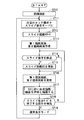
- step ST10 the map display device is turned on and an initial screen is displayed on the input / display unit 1.
- the initial screen is in a normal display mode that accepts a normal touch operation.
- step ST11 the user performs a predetermined operation on the initial screen displayed on the input / display unit 1 to shift to the slide display mode.
- the slide display mode is a mode in which the user can slide the upper map drawing screen by a gesture operation on the input / display unit 1.
- the display mode is changed by, for example, touch operation, button operation, icon operation, gesture operation, voice input, or the like.
- the overall control unit 402 stores a parameter for storing the type of display mode, and by referring to the parameter, it is possible to determine whether or not the display mode is the slide display mode. For example, it is determined whether or not the slide display mode is set when the parameter value is larger or smaller than a predetermined threshold value.
- the parameter may be set through a user operation such as an icon operation or voice input, or automatically changed according to preset conditions (including the vehicle state and the display state on the display surface). It may be. Further, an icon or the like may be displayed on the display screen of the input / display unit 1 so that the user can visually recognize whether or not the slide display mode is set.
- the slide distance X0 is set to 0 in step ST12.
- a first drawing screen and a second drawing screen are created.
- the creation is performed in the first information drawing unit 403 and the second information drawing unit 405 in accordance with the user input information as described above.
- the created first drawing screen is drawn and held in the first drawing screen holding unit 404, and the second drawing screen is drawn and held in the second drawing screen holding unit 406.
- step ST14 it is detected whether or not a slide operation for updating the display position of the map drawing screen overlaid has been performed.
- the input analysis unit 401 detects a user's input / display unit 1 gesture operation to detect a slide operation.
- step ST15 the slide distance X0 is updated based on the slide operation.
- step ST16 the drawing objects displayed on the first drawing screen and the second drawing screen are updated.
- the update corresponds to information that changes from time to time, such as changes in display contents that change with the movement of the vehicle and changes in traffic jam information.
- step ST17 the display position of the map drawing screen to be overlaid is determined according to the slide distance X0, and a composite drawing screen is created from the first drawing screen and the second drawing screen. Then, the composite drawing screen is drawn, that is, displayed on the input / display unit 1. Details will be described later.
- step ST18 the overall control unit 402 determines whether or not the input analysis unit 401 has detected a predetermined operation for ending the slide display mode.
- the process proceeds to step ST19, and when the operation is not detected, the process returns to step ST14.
- the slide display mode can be ended by, for example, touch operation, button operation, icon operation, gesture operation, voice recognition, or the like.
- step ST19 the mode is changed to the normal display mode, and the process returns to step ST11.
- step ST17 performed by the composite drawing unit 407 will be described with reference to FIGS.
- the board slide refers to a slide method in which the drawing object moves in the slide direction in conjunction with the slide.
- slide out when the drawing screens overlap each other, the upper drawing screen moves and moves out of the display surface. This is called slide out, and all of the drawing screens are out of the display surface due to slide out. Is called complete slide-out. Further, the complete slide-out is also referred to as a total displacement state, paying attention to the state where it does not overlap with the other drawing screen.
- the second drawing screen is described as the upper side and the first drawing screen as the lower side, but the reverse may be used.
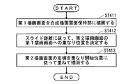
- step ST411 of FIG. 4 the first drawing screen held in the first drawing screen holding unit 404 is drawn in the composite drawing screen holding unit 408.
- step ST412 the overlapping position of the second drawing screen with respect to the first drawing screen is determined according to the slide distance X0 updated by the slide operation.
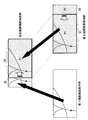
- 5 and 6 schematically show a drawing screen composition method when the display positions of the drawing objects displayed on the drawing screen are different from each other.
- the first drawing screen and the second drawing screen are completely overlapped, and the second drawing object is set to a position that masks all the first drawing objects.
- the attention point it is desirable that the first attention point on the first drawing screen and the second attention point on the second drawing screen overlap with each other on the display surface. That is, when a map around the vehicle is shown on the first drawing screen and the second drawing screen, it is desirable that the current position of the vehicle on each drawing screen is the same (in this case, The positions of the first attention point and the second attention point on the display surface are the same).
- the slide distance X0 is updated to a value other than 0, the overlapping position of the second drawing screen on the first drawing screen according to the position where the user touches the display surface in the gesture operation, for example, and the slide distance X0 based on the operation To decide.
- the user's gesture operation for updating the slide distance X0 includes a drag operation, a shutter operation, and a skip operation.
- the drag operation is realized by a gesture operation in which a user moves a predetermined direction while touching a finger touching the display surface, and the drawing screen moves following the gesture operation.
- the overlapping position of the second drawing screen with respect to the first drawing screen is shifted in the finger moving direction by the finger moving distance (sliding distance X0 in FIGS. 5 and 6).
- a drag operation in the right direction a position that is separated from the left end of the first drawing screen by the slide distance X0 in the right direction is determined as the overlap start position.
- a mode in which a composite drawing screen is created by a drag operation is called a drag mode.
- the second drawing screen slid by the drag operation in the drag mode remains in the slid position until the next gesture operation is performed.
- the second drawing screen may be returned to the overlapping position before the drag operation.
- the slide operation in this case is called a shutter operation in distinction from the drag operation, and a mode for creating a composite drawing screen by the shutter operation is called a shutter mode.
- Whether the sliding operation is performed in the drag mode or the shutter mode may be set by the user selecting an icon or the like in advance, or the input analysis unit 401 changes the number of fingers touching the display surface or the finger pressure. You may distinguish by detecting etc.
- the skipping operation is realized by performing an operation (flicking operation) such as playing a playing card with a finger touching the display surface.
- an operation flicking operation
- the overlapping position of the second drawing screen with respect to the first drawing screen is shifted in the direction of the skip operation by a distance corresponding to the skip operation.
- a position that is separated from the left end of the first drawing screen by the slide distance X0 in the right direction is determined as the overlap start position.
- the slide distance X0 is an amount that increases with time unlike the drag mode
- the second drawing screen slides to the right and finally slides out completely.
- the drawing screen that is overlaid in the direction specified by the predetermined touch operation is moved, and thereafter the operation to move according to the predetermined inertia is called a skip operation, and the mode for performing the operation is called the skip mode.
- the skip operation is determined under the following conditions and combinations.
- the skip operation of the condition (a) is distinguished from the drag operation by the moving speed of the finger.
- the speed set as the predetermined speed in (a) to (c) may be different for each condition.
- step ST413 the second drawing screen is drawn on the first drawing screen (data is overwritten) according to the overlapping position determined in step ST412, specifically, the overlapping start position. For example, when sliding out to the right side of the display surface, drawing is performed so that the left end of the second drawing screen matches the overlap start position.
- the area of the second drawing screen that does not overlap the first drawing screen (P2 in FIGS. 5 and 6) is not displayed on the display surface. That is, the first drawing object of the first drawing screen having a width of the slide distance X0 that does not overlap the second drawing screen, and the second drawing width D1 from the left end of the second drawing screen (excluding the width of X0 from the right end).
- the second drawing object (P1 in FIGS. 5 and 6) on the drawing screen is displayed on the display surface.
- the drawing object a, the drawing object b, the drawing object c, and the second background drawing object are drawn on the first drawing screen on which the drawing object A, the drawing object B, the drawing object C, and the first background drawing object are drawn.
- the second drawing screen is overlapped.
- the first point of interest on the first drawing screen is the drawing object A
- the second point of interest on the second drawing screen is the drawing object a.
- the first background drawing object and the second background drawing object are, for example, rectangular objects painted in cream color with the same size as the drawing screen size.
- a drawing object a, a drawing object b, and a drawing object c are drawn on the second background drawing object.
- the user touches the input / display unit 1 with a finger and moves the finger in the right direction in the figure while keeping the touch (drag operation). Then, since the overlapping start position of the upper second drawing screen is sequentially updated (1a ⁇ 2a ⁇ 3a or 1b ⁇ 2b ⁇ 3b), the entire second drawing screen moves to the right as if it slides on the board. Is displayed. That is, the drawing objects a, b, and c move to the right as if they are on the board.
- the first drawing screen and the second drawing screen are completely overlapped, and the drawing objects A, B, and C are masked by the second background drawing object.
- the second drawing screen is smaller than the first drawing screen, the second drawing screen only has to overlap the area of the first drawing screen corresponding to the size of the second drawing screen.
- the drawing object a and the drawing object b are displayed on the display surface of the input / display unit 1, but the rightmost drawing object c is removed from the display surface and is not displayed.
- the drawing object A is displayed, the drawing objects B and C are masked by the second background drawing object and are not displayed.
- the drawing object A which is the first attention point
- the drawing object a which is the second attention point
- the relative positional relationship between the upper second drawing screen and the lower first drawing screen changes as needed.
- the upper second drawing screen moves further to the right, and the drawing object b is also removed from the display surface of the input / display unit 1 and is not displayed.
- the drawing object A and the drawing object B are displayed, but the drawing object C is masked by the second background drawing object and is not displayed.
- the relative positional relationship between the upper second drawing screen and the lower first drawing screen changes as needed.
- map drawing screens do not overlap at all in the initial state (total displacement state), the second drawing screen moves from outside the display surface and gradually overlaps the first drawing screen, and finally Become.
- step ST431 the first drawing screen held in the first drawing screen holding unit 404 is drawn in the composite drawing screen holding unit 408.
- step ST432 the overlapping position of the second drawing screen on the first drawing screen is determined according to the slide distance X0 updated by the sliding operation.
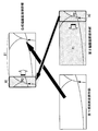
- 9 and 10 schematically illustrate a drawing screen composition method in the case where display positions of drawing objects displayed on the drawing screen are different from each other.
- the overlapping position is determined so that the second drawing screen is completely out of the display surface.
- the overlapping position is determined according to the slide distance X0 based on the user's gesture operation.
- the update of the slide distance X0 causes the first drawing point on the first drawing screen to approach the second attention point on the second drawing screen. It is desirable to determine the overlapping position on the first drawing screen.
- step ST433 the second drawing screen is drawn in an overlapping manner according to the overlapping position, specifically, the overlapping start position. For example, when sliding in from the left side of the display surface, the drawing is performed so that the right end of the second drawing screen matches the overlap start position.
- the portion that does not overlap the first drawing screen (P1 in FIGS. 9 and 10) is not displayed on the display surface.
- the first drawing object of the first drawing screen having a width D1 that does not overlap the second drawing screen, and the second drawing object of the second drawing screen of the slide distance X0 from the right end of the second drawing screen (FIG. 9). , 10 P2) is displayed on the display surface.
- the slide-in to the right by the board slide will be described.
- the second drawing screen moves to the right from outside the display surface and overlaps the first drawing screen.
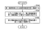
- step ST441 the first drawing screen held in the first drawing screen holding unit 404 is drawn in the composite drawing screen holding unit 408.
- step ST442 the overlapping position of the second drawing screen on the first drawing screen is determined according to the slide distance X0 updated by the sliding operation.
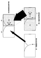
- 12 and 13 schematically show a drawing screen composition method in the case where display positions of drawing objects displayed on the drawing screen are different from each other.
- the overlapping position is determined at a position where the second drawing screen is completely outside the display surface. However, it is outside the display surface on the opposite side (right side) from the case shown in FIGS.
- the overlapping position of the second drawing screen on the first drawing screen is determined according to the slide distance X0 based on the gesture operation of the user related to the update.
- step ST443 the second drawing screen is drawn on the first drawing screen in accordance with the overlapping position, specifically, the overlapping start position. For example, when sliding in from the right side of the display surface, the drawing is performed so that the left end of the second drawing screen coincides with the overlap start position.
- the portion that does not overlap the first drawing screen (P2 in FIGS. 12 and 13) is not displayed on the display surface.
- the first drawing object of the first drawing screen having a width D1 that does not overlap the second drawing screen and the second drawing object of the second drawing screen (slid distance X0 from the left end of the second drawing screen) (FIG. 12, 13 is displayed on the display screen.
- the left and right arrangements are switched and displayed.
- the curtain slide refers to a slide method in which the display area is continuously changed (increased or decreased) while the display position of the drawing object is fixed.
- the upper second drawing screen slides out in the right direction on the display surface from the fully overlapped state.
- slide method is used to create the composite drawing screen may be distinguished according to the manner of user gesture operation, or may be set in advance according to the combination of maps to be displayed.
- step ST421 the first drawing screen held in the first drawing screen holding unit 404 is drawn in the composite drawing screen holding unit 408.
- step ST422 the overlapping position of the second drawing screen with respect to the first drawing screen is determined according to the slide distance X0 updated by the slide operation.
- the overlapping position is determined so that the first drawing screen and the second drawing screen completely overlap and the second drawing object masks all the first drawing object.
- the attention point it is desirable to determine the overlapping position so that the first attention point on the first drawing screen and the second attention point on the second drawing screen overlap and coincide on the display surface. . That is, when the surrounding map of the vehicle is shown on the first drawing screen and the second drawing screen, it is desirable to determine the overlapping position so that the current position of the vehicle on each drawing screen matches.
- the overlapping position of the second drawing screen on the first drawing screen is determined according to the slide distance X0 based on the user's gesture operation.
- the overlap start position is set with the distance (slide distance X0 in FIG. 15) moved by the user touching the display surface as an offset.
- the overlapping start position is set in the same manner. However, in the shutter mode, the user touches the display surface, and at the same time, the overlapping position is restored.
- the overlap start position of the second drawing screen is set with an amount that increases with time (the slide distance X0 in FIG. 15 increases with time) as an offset.
- step ST423 the second drawing screen is drawn on the first drawing screen in accordance with the overlapping position, specifically, the overlapping start position.
- drawing is performed so that the left end of the second drawing screen to be removed coincides with the overlap start position. That is, the position offset by the slide distance X0 from the left end of the second drawing screen coincides with the overlap start position.
- the portion (P1 in FIG. 15) removed from the first drawing screen in the second drawing screen is not displayed on the display surface.
- the first drawing object of the first drawing screen having a width of the slide distance X0 where the second drawing screen does not overlap, and the second drawing object of the second drawing screen (width D1 from the right end of the second drawing screen) P2) in FIG. 15 is displayed on the display surface.
- FIG. 16 By sequentially creating the composite drawing screen as described above, the operation shown in FIG. 16 (slide out by curtain slide) becomes possible.
- the drawing object a, the drawing object b, the drawing object c, and the second background drawing object are drawn on the first drawing screen on which the drawing object A, the drawing object B, the drawing object C, and the first background drawing object are drawn.
- the second drawing screen is overlapped.
- the first point of interest on the first drawing screen is a drawing object B
- the second point of interest on the second drawing screen is a drawing object b.
- the first background drawing object and the second background drawing object are, for example, rectangular objects painted in cream color with the same size as the drawing screen size.
- a drawing object a, a drawing object b, and a drawing object c are drawn on the second background drawing object.
- the overlapping start position of the upper second drawing screen is sequentially updated (1a ⁇ 2a ⁇ 3a, or 1b ⁇ 2b ⁇ 3b), and the second drawing screen continuously maintains the display position of the drawing object. It is displayed by sliding to draw (curtain slide).
- the first drawing screen and the second drawing screen are in a fully overlapped state, and the drawing object A, the drawing object B, and the drawing object C are respectively masked by the second background drawing object. ing.
- the second drawing screen is smaller than the first drawing screen, the second drawing screen only has to overlap the area of the first drawing screen corresponding to the size of the second drawing screen.
- the drawing object b and the drawing object c are displayed on the display surface of the input / display unit 1, but the leftmost drawing object a is not displayed.
- the drawing object A is displayed, the drawing objects B and C are masked by the second background drawing object and are not displayed.
- the relative positional relationship between the upper second drawing screen and the lower first drawing screen is maintained. That is, the first attention point and the second attention point always coincide on the display surface.
- the upper second drawing screen is further removed to the right, and the drawing object b is also removed from the display surface of the input / display unit 1 and is not displayed.
- the drawing object A and the drawing object B are displayed, but the drawing object C is masked by the second background drawing object and is not displayed.
- the drawing object B which is the first attention point
- the drawing object B is displayed at the position where the drawing object b, which is the second attention point, is removed. (See also FIG. 15). At this time, the relative positional relationship between the upper second drawing screen and the lower first drawing screen is maintained.
- the second background drawing object has been described as a single cream color.
- FIG. 16 when the gradation is applied so that the drawing object a and its vicinity are cream and the drawing object c and its vicinity are pink.
- the drawing background colors of 1a), (2a), and (3a) are close to the same pink.
- the range in which the lower first drawing screen can be seen is changed by sliding the second drawing screen without changing the display position of the second drawing object.
- the slide direction is not limited to a uniform direction such as left, right, up, down, but may be a slide that progresses radially around the user's touch position.
- various variations are conceivable, such as blinking the second drawing screen or displaying a fade when the slide progresses.
- the slide method shown above was able to be slid regardless of where the user touched or operated in the area where the second drawing screen is displayed
- the display range of the second drawing screen that accepts the slide operation May be limited.
- only the area in the vicinity of the boundary with the first drawing screen in the display range of the second drawing screen may be set as an area for receiving the slide operation.
- an area for accepting a slide operation may be displayed with an icon or the like.
- normal operation transitions by drag operation, skip operation, and simple touch operation can be received side by side, and a user-friendly device can be provided.
- the second background drawing object is a cream-colored rectangular object having the same size as the drawing screen.
- the shape of the background drawing object is not limited to a rectangle, and may be a trapezoid, an ellipse, or a holed object.
- the color of the background drawing object is not limited to a light color, and a display having a good design can be provided as long as it draws a gradation or a pattern.
- first drawing object and the second drawing object have been described as being stored in the first information storage unit 2 and the second information storage unit 3, respectively.
- One drawing object may be generated.
- the vehicle position mark and the like may be generated by the overall control unit 402 by a program.
- both or one of the background drawing objects may be generated by the overall control unit 402 by software processing.
- the method of rendering the background drawing object which is a rectangular drawing object, on the drawing screen has been described, but the method of generating the background drawing object is not limited to this method.
- the overall control unit 402 sets the background colors of the first drawing screen holding unit and the second drawing screen holding unit by software processing. It's okay.
- the overall control unit 402 performs the respective background by software processing.
- a color may be set.
- drawing object in this specification is a concept including a display object that is finally displayed on the input / display unit 1 by the above-described software processing.
- center display fixed slide a slide method in which a drawing object to be displayed at the center of the display area before and after the slide is fixed even if the area of the display area of the drawing screen is changed by the slide is referred to as a center display fixed slide.
- FIG. 17 is a flowchart showing details of the operation of creating a composite drawing screen (step ST17 in FIG. 3) using the center display fixed slide. As shown in FIG. 17, first, in step ST451, the composite drawing unit 407 draws the first drawing screen held in the first drawing screen holding unit 404 on the composite drawing screen holding unit 408.
- step ST452 the overlapping position of the second drawing screen with respect to the first drawing screen is determined according to the slide distance X0 updated by the slide operation.
- FIG. 18 schematically shows a method for synthesizing the drawing screen.
- the overlapping position of the second drawing screen on the first drawing screen is determined according to the user's gesture operation.
- the overlap start position is set with the distance (slide distance X0 in FIG. 18) moved by the user touching the display surface as an offset.
- the overlap start position is set in the same manner. However, in the shutter mode, the operation of touching the display surface by the user is completed and the overlap start position is restored.
- the overlap start position of the second drawing screen is set with the amount that increases with time (the slide distance X0 in FIG. 18 increases with time) as an offset.
- step ST453 the drawing range of the second drawing screen is drawn on the first drawing screen in accordance with the overlapping position, specifically, the overlapping start position.
- FIG. 18 shows an example in which the second drawing screen is slid out to the right side of the display surface by the slide distance X0. In this case, the area on the right side from the position offset by a half X0 / 2 of the slide distance X0 from the left end of the second drawing screen is the drawing range. Then, the drawing range is drawn on the first drawing screen so that the left end of the drawing range on the second drawing screen coincides with the overlap start position.
- the first drawing object on the first drawing screen having a width of the slide distance X0 on which the second drawing screen does not overlap, and the width D1 (the first point based on the position X0 / 2 from the left end of the second drawing screen)
- the second drawing object (P2 in FIG. 18) on the second drawing screen for the width that overlaps the drawing screen) is displayed on the display surface.
- FIG. 19 By repeatedly creating the composite drawing screen described above in the loop of steps ST14 to ST18 in FIG. 3, the operation shown in FIG. 19 (slide out by the center display fixed slide) is realized.
- the drawing objects a 1 , a 2 , b 1 , c 1 , c 2 are drawn on the first drawing screen on which the drawing objects A 1 , A 2 , B, C 1 , C 2 and the first background drawing object are drawn.
- the second drawing screen on which the second background drawing object is drawn is overlapped.
- the first background drawing object and the second background drawing object are, for example, rectangular objects painted in cream color with the same size as the drawing screen size.
- a drawing object a, a drawing object b, and a drawing object c are drawn on the second background drawing object.
- (1a), (2a), (3a) are schematic views of the first drawing screen and the second drawing screen as viewed from the side, and (1b), (2b), (3b) It is the schematic diagram which looked at the 1st drawing screen and the 2nd drawing screen from the upper surface direction.
- the user touches the input / display unit 1 with a finger and moves the finger in the right direction in the figure while keeping the touch (drag operation). Then, the overlapping start position of the second drawing screen with respect to the first drawing screen is sequentially updated (1a ⁇ 2a ⁇ 3a or 1b ⁇ 2b ⁇ 3b), and the second drawing screen is displayed at the center of the display area. While the object is fixed, it is displayed by sliding to the right of the screen (center display fixed slide).
- the first drawing screen and the second drawing screen are in a fully overlapped state, and the first drawing objects A 1 , A 2 , B, C 1 , C 2 are respectively in the second background. Masked by a drawing object.
- a second drawing object b is displayed at the center of the display area of the second drawing screen.
- the second drawing objects a 2 , b, and c 1 are displayed on the display surface, but the second drawing object a 1 at the left end is out of the drawing range,
- the drawing object c 2 is removed from the display surface of the input / display unit 1 and is not displayed.
- the first drawing object A 1 is displayed.
- a second drawing object b is displayed at the center of the second drawing screen.
- the upper second drawing screen is further removed from the display surface of the input / display unit 1, and the second drawing object c1 is not displayed. Also, the second drawing object a 2 is not displayed outside the drawing range. At this time, b is displayed at the center of the second drawing screen.
- the center display fixed slide fixes the content (second drawing object b) displayed at the center before and after the slide, so that the content displayed at the center of the original display area is fixed and displayed.
- This is a sliding method suitable for reducing the area.
- FIG. 20 shows a display example in which an upper map displaying only a national road around the vehicle position is overlaid on a lower map displaying a national road and a local road around the vehicle position. That is, a map of national roads and local roads is displayed on the first drawing screen, and a map of only national roads is displayed on the second drawing screen.
- the route of the vehicle is displayed in the center in the horizontal direction of the display area. Since the vehicle position is displayed below the center in the vertical direction of the display area, the route in the traveling direction is displayed longer than the route that has passed.
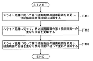
- FIG. 21 is a flowchart showing the details of the operation of creating a composite drawing screen (step ST17 in FIG. 3) that realizes the first specific example, and FIG. 22 shows the drawing range of each drawing screen.
- the first information drawing unit 403 draws the first drawing screen for the entire display area around the current display range on the first drawing screen holding unit 404, as shown in FIG. 22 (1a). Among them, the drawing range indicated by the bold frame is drawn on the composite drawing screen.
- the second information drawing unit 405 draws the second drawing screen for the entire display area around the current display range on the second drawing screen holding unit 406. Among them, the drawing range indicated by the bold frame is drawn on the composite drawing screen.
- step ST461 the composite drawing unit 407 changes the drawing range of the first drawing screen according to the slide distance, and then draws the drawing range in the composite drawing screen storage unit 408. For example, if the user performs an operation of dragging the second drawing screen to the right by X0, the drawing range of the first drawing screen is extended to the left by X0 / 2 as shown in FIG. 22 (2a).
- step ST462 the overlapping position of the second drawing screen with respect to the first drawing screen is updated according to the slide distance.
- the overlap start position is shifted rightward by the slide distance X0.
- step ST463 after changing the drawing range of the second drawing screen according to the slide distance, drawing is performed on the first drawing screen.
- the left end of the drawing range of the second drawing screen is shifted to the right by X0 / 2 as shown in FIG. 22 (2b).
- the drawing range on the second drawing screen is drawn on the first drawing screen so that the left end of the drawing range on the second drawing screen matches the overlap start position updated in step ST462.
- the second drawing screen is slid by the distance X0, and the position and route of the vehicle are not changed at the center of the display area before and after the slide on any drawing screen. Is displayed.
- the first drawing object displayed at the center of the display area is fixed on the first drawing screen in which the area of the display area changes.
- the display position of the first drawing object on the composite drawing screen changes.
- the second drawing screen slides to the right by X0
- the first drawing screen slides to the right by X0 / 2.
- FIG. 20 (1) if you want to display a wider area map with national and local roads displayed on the lower map, the upper map as shown in FIGS. 20 (2) and (3) By sliding to the right, the display area of the lower map can be increased.
- the vehicle and the route are always displayed at the center of the display range, and local roads around the vehicle are displayed according to the display area. Therefore, the user can smoothly change the display area around the own vehicle while grasping the own vehicle position.
- the center display content of the first drawing screen is fixed by changing the drawing range of the first drawing screen.
- the center display content may be fixed by re-creating a drawing object while maintaining the drawing range of the first drawing screen.
- FIG. 23 shows a display example in which an upper map that displays a map of the vicinity of the vehicle position is superimposed on a lower map that displays an overall route map from the vehicle position to the destination. That is, the first drawing screen displays the entire route map, and the second drawing screen displays the vehicle position peripheral view.
- the route of the vehicle is displayed at the center in the horizontal direction of the display area. Since the vehicle position is displayed below the center in the vertical direction of the display area, the route in the traveling direction is displayed longer than the route that has passed.
- the upper map displays the vehicle position and route near the center of the display area, but there is an area where nothing is displayed at the left and right ends. There is no inconvenience in the display of the upper map even if it is narrowed. Therefore, as shown in FIGS. 23 (2) and 23 (3), the upper map is center-fixed and slid in the right direction within a range in which the vehicle position peripheral view is visible, and the lower map display area is expanded.
- the scale will be changed according to the expansion of the display area.
- the display scale of the first drawing object on the first drawing screen is changed in accordance with the overlap control and the entire path diagram is displayed in the full display area, a display screen with a limited area can be used effectively. It becomes possible to display the drawing screen.
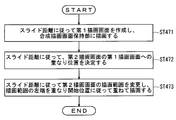
- FIG. 24 is a flowchart showing details of a composite drawing screen creation operation (step ST17 in FIG. 3) for realizing the second specific example.
- the flowchart of FIG. 24 will be described below by taking as an example a case where the user performs an operation of sliding the second drawing screen to the right by X0.
- step ST471 a new first drawing screen in which the scale of the first drawing object is changed according to the slide distance is created, and the first drawing screen is drawn on the composite drawing screen holding unit.
- the second drawing screen is slid to the right by X0, the width of the display area of the first drawing screen is increased by X0, so the scale of the first drawing object is changed to fit the new display area.
- the first information drawing unit 403 obtains a new first drawing object from the first information storage unit 2 and draws a new first drawing screen in the first drawing screen holding unit 404 based on this operation. Realize.
- the composite drawing unit 407 then draws a new first drawing screen on the composite drawing screen holding unit 408.
- steps ST472 and 473 are the same as steps ST462 and 463 of FIG.
- linked drawing objects is linked map scale.
- the current map is displayed on the second drawing screen and the past map is displayed on the first drawing screen at a scale of 1/2000.
- the current map at a scale of 1 / 50,000 is displayed on the second drawing screen and the past displayed on the first drawing screen is displayed.
- the display scale of the map is also changed to 1 / 50,000.
- the current map and the past map can be easily compared by linking the scales on the first drawing screen and the second drawing screen.
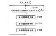
- FIG. 25 is a flowchart showing the operation of the map display device realizing the third specific example.
- the overall control unit 402 determines whether or not the user has inputted a display setting change input to the input / display unit 1 (step ST230).
- a display setting change input to the input / display unit 1 (step ST230).
- a first drawing screen is created (step ST231). Specifically, the first information drawing unit 403 newly acquires the first drawing object from the first information storage unit 2 and draws the first drawing screen in the first drawing screen holding unit 404.
- a map with a scale of 1 / 50,000 is newly created as the first drawing screen in conjunction with the change operation on the second drawing screen.
- a second drawing screen is created (step ST232). Specifically, the second information drawing unit 405 newly acquires a second drawing object from the second information storage unit 3 and draws the second drawing screen in the second drawing screen holding unit 406.
- a map with a scale of 1 / 50,000 is newly created as the second drawing screen, reflecting the display setting change operation input by the user in step ST230.
- the composite drawing unit 407 creates a composite drawing screen from the first drawing screen and the second drawing screen (step ST233).
- the drawing range of the second drawing screen and the overlapping position with respect to the first drawing screen are the same as before the display setting is changed.
- the composite drawing screen holding unit 408 is overlapped with the first drawing screen so that the drawing range end of the second drawing screen coincides with the overlap start position. To draw.
- the composite drawing screen held in the composite drawing screen holding unit 408 is output to the input / display unit 1 and displayed on the display surface of the input / display unit 1.
- the input / display unit 1 has a configuration in which an input unit that receives user input information and a display unit that displays a map drawing screen based on the received input information and operation control by the control unit 4 are integrated.
- the structure for realizing these functions may be provided separately.
- the drawing objects displayed on the drawing screen are not limited to those related to map display, and various drawing objects according to the user's request can be displayed.
- the input / display unit 1 is realized by a touch panel as in the present embodiment and the overlap of the drawing screens is changed by a gesture operation, the operation can be easily performed.
- screen operations are performed by touching operation icons displayed on a touch panel, mechanical switches, or dial operations, and the user interface is not always easy to use.
- a user interface that is easy to use can be realized by adopting a gesture operation that is used in a mobile terminal having a touch panel, such as a smartphone, as in the present invention.
- the input / display unit 1 is not limited to a normal touch panel, and may be a three-dimensional touch panel capable of detecting the proximity and contact of a finger using a capacitance detection type touch panel.
- the first information storage unit 2 and the second information storage unit 3 may be different storage media as shown in FIG. 1, or may be a case where both are included in one storage medium. Moreover, the case where map information etc. are acquired by communicating with the storage medium provided outside may be sufficient.
- the slide method in the present embodiment is an example, and the map drawing screen may be updated by a method other than the slide method in the slide display mode.
- the upper drawing screen and the lower drawing screen do not need to have the same size. Note that the drawing screen does not have to be the size of the entire display surface.
- the scale change of the lower map with respect to the slide of the upper map may be continuous or stepwise. Also good. Further, when the display areas of the upper map and the lower map are equal, the scales of both maps may be the same. Further, the scale of the upper map may be changed according to the slide of the upper map, and the scale of the lower map may be fixed.
- the road map is displayed on both the first and second drawing screens, but one drawing screen may not display the map.
- the first drawing screen is a 50-sound search icon screen or a route guidance screen
- the size of these screens can be freely set according to the slide area, so that the map display is easy to search or view and is easy to use. improves.
- the scale of the map is given as an example of the display setting that is linked between the drawing screens.
- other display such as the scale of the height of the three-dimensional map, the line-of-sight angle and the color tone in Bird View (registered trademark)
- the settings may be linked between the drawing screens.
- the map display device of the present embodiment is a map display device that can at least partially overlap a plurality of drawing screens including a first drawing screen and a second drawing screen.
- the first drawing screen has at least one first drawing object
- the second drawing screen has at least one second drawing object.
- At least one of the first drawing object and the second drawing object includes a drawing object related to map information.
- the first drawing screen and the second drawing screen have the same or different sizes.
- the map display device controls an overlapping state of the first and second drawing screens in accordance with an input unit that receives an operation input related to a user's drawing screen display and a user's operation input received by the input unit.
- one of the first and second drawing objects is provided with a control unit 4 that masks the other and outputs it to the display unit.
- the control unit 4 changes the other drawing screen display in conjunction with a user operation input to one of the first and second drawing screens received by the input unit. Therefore, a user-friendly map display can be performed.
- control unit 4 continuously changes the overlapping state of the first and second drawing screens by sliding the other of the first and second drawing screens. Therefore, the user can easily grasp the relationship between the two maps.
- the overlapping state of the first and second drawing screens is controlled by the center display fixed slide in which the drawing object displayed at the center of the display area is fixed before and after the slide.
- the center display fixed slide the content displayed in the center before and after the slide does not change, so that the display area can be arbitrarily adjusted by the slide while leaving the content to be displayed.
- the input unit and the display unit are integrally formed as the input / display unit 1 of the display device with a touch panel, the convenience of the user's input operation is improved.
- the second drawing object masks the first drawing object
- the control unit 4 responds to the user's operation input for sliding the second drawing screen received by the input unit.
- the first drawing object is created, and the first drawing object is changed so that the content displayed at the center of the region where the second drawing screen of the first drawing screen does not overlap before and after the overlap control.
- the control unit 4 changes the display area of the first drawing screen so that the content displayed at the center of the area where the second drawing screen of the first drawing screen does not overlap before and after the overlap control.
- control unit 4 changes the display scale of the first drawing object in accordance with a user operation input that slides the second drawing screen received by the input unit. For example, when it is desired to enlarge and display the first drawing object on the first drawing screen, the display area of the first drawing screen is enlarged by sliding the second drawing screen to correspond to the size of the display area. Since the first drawing object is enlarged, the map display is convenient for the user.
- Both the first and second drawing objects include a drawing object related to map information
- the control unit 4 sets the map scales on the first drawing screen and the second drawing screen in accordance with the user's operation input received by the input unit. Change in conjunction. Therefore, the user can easily compare the map information on both drawing screens.
- the first and second drawing objects are both drawing objects related to the stereoscopic map display
- the control unit 4 sets the height scale on the first and second drawing screens according to the user's operation input received by the input unit. Change in conjunction. Therefore, the user can easily compare the map information on both drawing screens.
- both the first and second drawing objects include drawing objects relating to bird's eye view information
- the control unit 4 interlocks the line-of-sight angles on the first and second drawing screens according to the user's operation input received by the input unit. change. Therefore, the user can easily compare the map information on both drawing screens.
- the map display device method is a map display method for displaying a plurality of drawing screens including a first drawing screen and a second drawing screen at least partially overlapping each other.
- the first drawing screen displays at least one first drawing object
- the second drawing screen displays at least one second drawing object
- at least one of the first drawing object and the second drawing object is a drawing object related to map information.
- the first drawing screen and the second drawing screen have the same or different sizes.
- the map display apparatus method includes (a) a step of accepting an operation input related to a drawing screen display of a user, (b) a step of displaying a plurality of drawing screens, and (c) a step (a) prior to step (b).
- step 1 the overlapping state of the first and second drawing screens is controlled. In the overlapping portion of the first and second drawing screens, one of the first and second drawing objects masks the other. And (d) prior to step (b), a step of changing the other drawing screen display in conjunction with a user operation input to one of the first and second drawing screens received in step (a). With. Therefore, a user-friendly map display can be performed.
- SYMBOLS 1 Input and display part 2 1st information storage part, 3rd 2nd information storage part, 4 control part, 401 input analysis part, 402 whole control part, 403 1st information drawing part, 404 1st drawing screen holding part, 405 2nd information drawing part, 406 2nd drawing screen holding part, 407 Composite drawing part, 408 Composite drawing screen holding part.
Landscapes
- Engineering & Computer Science (AREA)
- Radar, Positioning & Navigation (AREA)
- Remote Sensing (AREA)
- Physics & Mathematics (AREA)
- General Physics & Mathematics (AREA)
- Automation & Control Theory (AREA)
- General Engineering & Computer Science (AREA)
- Theoretical Computer Science (AREA)
- Human Computer Interaction (AREA)
- User Interface Of Digital Computer (AREA)
- Navigation (AREA)
- Instructional Devices (AREA)
- Processing Or Creating Images (AREA)
Abstract
Priority Applications (5)
| Application Number | Priority Date | Filing Date | Title |
|---|---|---|---|
| PCT/JP2012/050512 WO2013105252A1 (fr) | 2012-01-12 | 2012-01-12 | Dispositif d'affichage de carte et procédé d'affichage de carte |
| CN201280066238.3A CN104040291A (zh) | 2012-01-12 | 2012-01-12 | 地图显示装置以及地图显示方法 |
| DE112012005649.3T DE112012005649T5 (de) | 2012-01-12 | 2012-01-12 | Kartenanzeigevorrichtung und Kartenanzeigeverfahren |
| JP2013553151A JP5774133B2 (ja) | 2012-01-12 | 2012-01-12 | 地図表示装置および地図表示方法 |
| US14/353,675 US20140298224A1 (en) | 2012-01-12 | 2012-01-12 | Map display device and map display method |
Applications Claiming Priority (1)
| Application Number | Priority Date | Filing Date | Title |
|---|---|---|---|
| PCT/JP2012/050512 WO2013105252A1 (fr) | 2012-01-12 | 2012-01-12 | Dispositif d'affichage de carte et procédé d'affichage de carte |
Publications (1)
| Publication Number | Publication Date |
|---|---|
| WO2013105252A1 true WO2013105252A1 (fr) | 2013-07-18 |
Family
ID=48781223
Family Applications (1)
| Application Number | Title | Priority Date | Filing Date |
|---|---|---|---|
| PCT/JP2012/050512 Ceased WO2013105252A1 (fr) | 2012-01-12 | 2012-01-12 | Dispositif d'affichage de carte et procédé d'affichage de carte |
Country Status (5)
| Country | Link |
|---|---|
| US (1) | US20140298224A1 (fr) |
| JP (1) | JP5774133B2 (fr) |
| CN (1) | CN104040291A (fr) |
| DE (1) | DE112012005649T5 (fr) |
| WO (1) | WO2013105252A1 (fr) |
Cited By (1)
| Publication number | Priority date | Publication date | Assignee | Title |
|---|---|---|---|---|
| JP2021516818A (ja) * | 2018-08-09 | 2021-07-08 | ▲騰▼▲訊▼科技(深▲セン▼)有限公司 | アプリケーションプログラムの表示適応方法及びその装置、端末、記憶媒体、並びにコンピュータプログラム |
Families Citing this family (6)
| Publication number | Priority date | Publication date | Assignee | Title |
|---|---|---|---|---|
| KR101126516B1 (ko) * | 2011-02-25 | 2012-03-22 | 팅크웨어(주) | 정보를 수신하는 전자기기 및 방법, 정보를 수신하는 방법을 수행하는 프로그램을 기록한 기록매체 |
| CN103473227B (zh) * | 2012-06-06 | 2015-07-01 | 腾讯科技(深圳)有限公司 | 微博动态显示方法和装置 |
| JP5791744B1 (ja) * | 2014-03-18 | 2015-10-07 | 株式会社ドワンゴ | 端末装置、動画表示方法、及びプログラム |
| CN109769063B (zh) * | 2018-12-25 | 2021-01-15 | 努比亚技术有限公司 | 一种屏幕显示方法、设备及计算机可读存储介质 |
| US12236072B2 (en) * | 2021-09-13 | 2025-02-25 | Apple Inc. | Displaying on a display with an irregular feature |
| CN114386130B (zh) * | 2022-01-19 | 2025-05-16 | 中国核电工程有限公司 | 一种模型修改的方法及装置 |
Citations (4)
| Publication number | Priority date | Publication date | Assignee | Title |
|---|---|---|---|---|
| JP2001174271A (ja) * | 1999-12-21 | 2001-06-29 | Kenwood Corp | ナビゲーション装置 |
| JP2002296046A (ja) * | 2001-03-29 | 2002-10-09 | Nippon Seiki Co Ltd | 表示装置の表示方法 |
| JP2003240589A (ja) * | 1996-10-01 | 2003-08-27 | Aisin Aw Co Ltd | ナビゲーション装置及び案内経路表示のためのコンピュータプログラムを記憶した媒体 |
| JP2004233333A (ja) * | 2003-01-06 | 2004-08-19 | Alpine Electronics Inc | ナビゲーション用立体表示方法およびナビゲーション装置 |
Family Cites Families (9)
| Publication number | Priority date | Publication date | Assignee | Title |
|---|---|---|---|---|
| DE69315969T2 (de) * | 1992-12-15 | 1998-07-30 | Sun Microsystems Inc | Darstellung von Informationen in einem Anzeigesystem mit transparenten Fenstern |
| TW371334B (en) * | 1994-03-18 | 1999-10-01 | Hitachi Ltd | Method for retrieving database with image information |
| JP3992452B2 (ja) * | 2000-11-09 | 2007-10-17 | 日立ソフトウエアエンジニアリング株式会社 | 変化検出装置、変化検出方法及び該方法に係るプログラムを記憶した記憶媒体並びにシステム |
| DE102006037156A1 (de) * | 2006-03-22 | 2007-09-27 | Volkswagen Ag | Interaktive Bedienvorrichtung und Verfahren zum Betreiben der interaktiven Bedienvorrichtung |
| WO2009126710A2 (fr) * | 2008-04-10 | 2009-10-15 | Perceptive Pixel, Inc. | Procédés mettre en interface des dispositifs à entrées multiples et des systèmes d'affichage à entrées multiples en utilisant des techniques d'interfaçage |
| CN101672648A (zh) * | 2008-09-12 | 2010-03-17 | 富士通天株式会社 | 信息处理装置、图像处理装置 |
| US20120249585A1 (en) * | 2009-11-09 | 2012-10-04 | Pioneer Solutions Corporation | Information processing device, method thereof, and display device |
| US8902085B1 (en) * | 2011-05-17 | 2014-12-02 | Raytheon Company | Integrated 3D audiovisual threat cueing system |
| US20130162665A1 (en) * | 2011-12-21 | 2013-06-27 | James D. Lynch | Image view in mapping |
-
2012
- 2012-01-12 WO PCT/JP2012/050512 patent/WO2013105252A1/fr not_active Ceased
- 2012-01-12 DE DE112012005649.3T patent/DE112012005649T5/de not_active Ceased
- 2012-01-12 JP JP2013553151A patent/JP5774133B2/ja not_active Expired - Fee Related
- 2012-01-12 US US14/353,675 patent/US20140298224A1/en not_active Abandoned
- 2012-01-12 CN CN201280066238.3A patent/CN104040291A/zh active Pending
Patent Citations (4)
| Publication number | Priority date | Publication date | Assignee | Title |
|---|---|---|---|---|
| JP2003240589A (ja) * | 1996-10-01 | 2003-08-27 | Aisin Aw Co Ltd | ナビゲーション装置及び案内経路表示のためのコンピュータプログラムを記憶した媒体 |
| JP2001174271A (ja) * | 1999-12-21 | 2001-06-29 | Kenwood Corp | ナビゲーション装置 |
| JP2002296046A (ja) * | 2001-03-29 | 2002-10-09 | Nippon Seiki Co Ltd | 表示装置の表示方法 |
| JP2004233333A (ja) * | 2003-01-06 | 2004-08-19 | Alpine Electronics Inc | ナビゲーション用立体表示方法およびナビゲーション装置 |
Cited By (3)
| Publication number | Priority date | Publication date | Assignee | Title |
|---|---|---|---|---|
| JP2021516818A (ja) * | 2018-08-09 | 2021-07-08 | ▲騰▼▲訊▼科技(深▲セン▼)有限公司 | アプリケーションプログラムの表示適応方法及びその装置、端末、記憶媒体、並びにコンピュータプログラム |
| US11231845B2 (en) | 2018-08-09 | 2022-01-25 | Tencent Technology (Shenzhen) Company Limited | Display adaptation method and apparatus for application, and storage medium |
| JP7230055B2 (ja) | 2018-08-09 | 2023-02-28 | ▲騰▼▲訊▼科技(深▲セン▼)有限公司 | アプリケーションプログラムの表示適応方法及びその装置、端末、記憶媒体、並びにコンピュータプログラム |
Also Published As
| Publication number | Publication date |
|---|---|
| JPWO2013105252A1 (ja) | 2015-05-11 |
| US20140298224A1 (en) | 2014-10-02 |
| JP5774133B2 (ja) | 2015-09-02 |
| DE112012005649T5 (de) | 2014-10-09 |
| CN104040291A (zh) | 2014-09-10 |
Similar Documents
| Publication | Publication Date | Title |
|---|---|---|
| JP5606640B2 (ja) | 地図表示装置および地図表示方法 | |
| JP5774133B2 (ja) | 地図表示装置および地図表示方法 | |
| JP5496434B2 (ja) | 地図表示装置および地図表示方法 | |
| JP5721865B2 (ja) | 地図表示装置および地図表示方法 | |
| JP5800914B2 (ja) | 地図表示装置および地図表示方法 | |
| JP5875605B2 (ja) | 地図表示装置 | |
| JP5726333B2 (ja) | 地図表示装置および地図表示方法 | |
| JP5805216B2 (ja) | 地図表示装置および地図表示方法 | |
| JP6433347B2 (ja) | 地図表示制御装置および地図の自動スクロール方法 | |
| JP6351432B2 (ja) | 地図描画システムおよび地図描画方法 | |
| JP5818917B2 (ja) | 地図表示装置および地図表示方法 | |
| JP2015011429A (ja) | 表示システムおよび表示プログラム |
Legal Events
| Date | Code | Title | Description |
|---|---|---|---|
| 121 | Ep: the epo has been informed by wipo that ep was designated in this application |
Ref document number: 12864698 Country of ref document: EP Kind code of ref document: A1 |
|
| ENP | Entry into the national phase |
Ref document number: 2013553151 Country of ref document: JP Kind code of ref document: A |
|
| WWE | Wipo information: entry into national phase |
Ref document number: 14353675 Country of ref document: US |
|
| WWE | Wipo information: entry into national phase |
Ref document number: 1120120056493 Country of ref document: DE Ref document number: 112012005649 Country of ref document: DE |
|
| 122 | Ep: pct application non-entry in european phase |
Ref document number: 12864698 Country of ref document: EP Kind code of ref document: A1 |