WO2013105461A1 - 携帯端末装置の充電システム及び携帯端末装置 - Google Patents
携帯端末装置の充電システム及び携帯端末装置 Download PDFInfo
- Publication number
- WO2013105461A1 WO2013105461A1 PCT/JP2012/084027 JP2012084027W WO2013105461A1 WO 2013105461 A1 WO2013105461 A1 WO 2013105461A1 JP 2012084027 W JP2012084027 W JP 2012084027W WO 2013105461 A1 WO2013105461 A1 WO 2013105461A1
- Authority
- WO
- WIPO (PCT)
- Prior art keywords
- terminal device
- charging
- mobile terminal
- secondary battery
- communication device
- Prior art date
- Legal status (The legal status is an assumption and is not a legal conclusion. Google has not performed a legal analysis and makes no representation as to the accuracy of the status listed.)
- Ceased
Links
Images


Classifications
-
- H—ELECTRICITY
- H02—GENERATION; CONVERSION OR DISTRIBUTION OF ELECTRIC POWER
- H02J—ELECTRIC POWER NETWORKS; CIRCUIT ARRANGEMENTS OR SYSTEMS FOR SUPPLYING OR DISTRIBUTING ELECTRIC POWER; SYSTEMS FOR STORING ELECTRIC ENERGY
- H02J7/00—Circuit arrangements for charging or discharging batteries or for supplying loads from batteries
- H02J7/40—Circuit arrangements for charging or discharging batteries or for supplying loads from batteries characterised by the exchange of charge or discharge related data
- H02J7/42—Circuit arrangements for charging or discharging batteries or for supplying loads from batteries characterised by the exchange of charge or discharge related data with electronic devices having internal batteries, e.g. mobile phones
-
- H—ELECTRICITY
- H02—GENERATION; CONVERSION OR DISTRIBUTION OF ELECTRIC POWER
- H02J—ELECTRIC POWER NETWORKS; CIRCUIT ARRANGEMENTS OR SYSTEMS FOR SUPPLYING OR DISTRIBUTING ELECTRIC POWER; SYSTEMS FOR STORING ELECTRIC ENERGY
- H02J50/00—Circuit arrangements or systems for wireless supply or distribution of electric power
- H02J50/10—Circuit arrangements or systems for wireless supply or distribution of electric power using inductive coupling
-
- H—ELECTRICITY
- H04—ELECTRIC COMMUNICATION TECHNIQUE
- H04M—TELEPHONIC COMMUNICATION
- H04M1/00—Substation equipment, e.g. for use by subscribers
- H04M1/72—Mobile telephones; Cordless telephones, i.e. devices for establishing wireless links to base stations without route selection
- H04M1/724—User interfaces specially adapted for cordless or mobile telephones
- H04M1/72403—User interfaces specially adapted for cordless or mobile telephones with means for local support of applications that increase the functionality
- H04M1/72409—User interfaces specially adapted for cordless or mobile telephones with means for local support of applications that increase the functionality by interfacing with external accessories
- H04M1/72412—User interfaces specially adapted for cordless or mobile telephones with means for local support of applications that increase the functionality by interfacing with external accessories using two-way short-range wireless interfaces
-
- H—ELECTRICITY
- H04—ELECTRIC COMMUNICATION TECHNIQUE
- H04M—TELEPHONIC COMMUNICATION
- H04M1/00—Substation equipment, e.g. for use by subscribers
- H04M1/02—Constructional features of telephone sets
- H04M1/04—Supports for telephone transmitters or receivers
-
- H—ELECTRICITY
- H04—ELECTRIC COMMUNICATION TECHNIQUE
- H04M—TELEPHONIC COMMUNICATION
- H04M2250/00—Details of telephonic subscriber devices
- H04M2250/02—Details of telephonic subscriber devices including a Bluetooth® interface
Definitions
- the present invention relates to a charging system for a mobile terminal device and a mobile terminal device.
- the present invention relates to a charging system for a portable terminal device and a portable terminal capable of receiving charging power supplied from a charging pad in a non-contact state in the portable terminal device and charging a built-in secondary battery of the portable terminal device. Relates to the device.
- Patent Document 1 discloses a technique for efficiently charging a secondary battery in a non-contact manner. Specifically, when the plug is connected to a commercial power outlet, the frequency conversion circuit converts the commercial power supply power into converted power having a predetermined frequency equal to three parallel resonance circuits. The three parallel resonance circuits of the power reception unit function as reception means for receiving power from the transmission means of the power transmission unit. The two rectifier circuits of the power receiving unit convert the output of the receiving unit into DC power.
- Patent Document 2 discloses a charging stand having a hands-free call function. With this configuration, there is no need to worry about wearing headphones or power, and the mobile phone can be used without any trouble. Specifically, it is configured such that a hands-free call of a mobile phone can be performed by a hands-free circuit using a speaker and a microphone provided on the charging stage.
- Patent Document 3 discloses a wireless device connection system that can easily perform wireless connection between a plurality of devices. Specifically, a wireless device connection system including a first terminal device including a first control unit, a second wireless connection interface, and a second terminal device including a second control unit that activates the interface. Disclosure.
- the second terminal device includes a holder including a detector that detects that the first terminal device is set and outputs a set signal.
- the second control unit of the second terminal device activates the second wireless connection interface in response to the set signal sent from the detector, and wirelessly communicates between the first terminal device and the second terminal device. Establish a connection.
- Patent Document 4 discloses a configuration in which a communication terminal device having a function of displaying caller information when a call is received and mail is received has a function of preventing information leakage due to a third party seeing the incoming call display. Is disclosed. Specifically, a condition for performing confidential display, a caller identification mark, and the like are set in the storage unit in advance. Then, when the communication terminal device receives an incoming call that satisfies the confidential display condition, the confidential information using the mark or the like is used instead of the sender information stored in the storage unit or the sender information registered in the confidential address book. Announce the incoming call by display. When an operation for canceling the confidential display is performed, the display is switched to a normal incoming call notification.
- Japanese Unexamined Patent Publication No. 11-98706 Japanese Patent Laid-Open No. 2002-247173 Japanese Unexamined Patent Publication No. 2004-312538 Japanese Unexamined Patent Publication No. 2010-183532
- a non-contact charging system employing an electromagnetic induction method has a magnetic field coupling between a primary coil on a power transmission side and a secondary coil mounted on a device on a power receiving side. It has a mechanism to carry out electric power transmission with the induced current. For this reason, when the portable terminal device to be charged is removed from the charger of the non-contact charging system, the magnetic field coupling between the coils is lost. As a result, charging is stopped. More specifically, when the mobile terminal device is charged using a known non-contact charging system, there are problems shown in the following items (1) to (3).
- Non-contact charging is interrupted by incoming voice (for example, Patent Documents 1, 3, and 4).
- a mobile terminal device having a communication function such as a telephone performs this contactless charging.
- the user when there is an incoming voice call or the like during charging, the user must make a call with the mobile terminal device removed from the charging pad. For this reason, charging is stopped. If the mobile terminal device is removed from the charging pad when the remaining battery level is low, the built-in battery will run out during a call or operation in another scene, making it impossible to use the mobile terminal device. It may come. In that case, the use of the mobile terminal device is significantly limited.
- Patent Document 2 can avoid this problem for the time being, there is another problem that a call in a hand-free state is forced.
- Item (2) Stopping of charging that the user does not know may occur (for example, Patent Documents 1 to 4).
- the mobile terminal device is contactlessly charged in a general home or a public place.
- the mobile phone being charged for some reason (for example, manual intervention by a third party or occurrence of an earthquake) If the terminal device is detached from the charging pad, the occurrence of this situation is not notified. In that case, until the user discovers the occurrence of the situation, the mobile phone device remains in a state where charging is interrupted.
- Patent Documents 1 to 3 User privacy may be impaired (for example, Patent Documents 1 to 3).
- the non-contact charging system has a restriction that it must be placed on the charging pad with the secondary coil side of the portable terminal device facing down. For this reason, if the mobile terminal device receives an incoming voice signal or the like during non-contact charging of the mobile terminal device in a general home or public place, the mobile terminal device receives a call via the LCD display screen of the mobile terminal device. It is inevitable that the name of the sender is seen by the three parties. In this case, the user's privacy is impaired.
- the technique described in Patent Document 4 can avoid this problem for the time being. However, this technique leaves the inconvenience that the user of the mobile terminal device has to know in advance the meaning of the mark displayed on the LCD display screen. Therefore, it has been necessary to solve these problems and improve the convenience of non-contact charging by some means.
- An example of an object of the present invention is to provide a charging system for a mobile terminal device and a mobile terminal device that solve the above-described problems.
- a charging system for a mobile terminal device includes a mobile terminal device including a secondary battery and a control unit, a charging pad that supplies power for charging the secondary battery in a contactless manner, And a communication device that performs local communication with the mobile terminal device.
- the controller is configured to charge the portable terminal device using the charging pad of the portable terminal device in a state in which designation to use the communication device is set and the communication between the portable terminal device and the communication device is possible.
- the incoming call is transferred from the mobile terminal device to the communication device, and the user of the mobile terminal device is allowed to talk to the incoming caller via the communication device.
- a portable terminal device includes at least a transmission / reception unit communicably connected to a cellular phone network, a charging unit that charges a secondary battery, a detection unit that detects a charging state of the secondary battery, and information.
- a display unit for displaying, a local communication unit for communicating with an external local communication device, and a control unit are provided. If the control unit is connected to the local communication device so as to be able to communicate with the local battery device when charging the secondary battery, the control unit performs local communication on the incoming and incoming contents via the transmission / reception unit and the charging status of the secondary battery. Notify the user via the device. The control unit performs control so as not to perform display on the incoming display unit when there is a designation not to perform display on the display unit.
- the mobile terminal device even when there is an incoming voice call while the mobile terminal device is placed on the charging pad and performing contactless charging, the mobile terminal device is already paired with a local communication device. Then, a voice call can be smoothly started in a state where the non-contact charging state is maintained.
- FIG. 1 is a configuration diagram showing an overall configuration of a charging system for a portable terminal device according to an embodiment of the present invention.
- the charging system for a mobile terminal device according to the present embodiment includes a mobile terminal device 1, a charging pad 2, and a Bluetooth (registered trademark) communication device 3 (local communication unit).
- the charging pad 2 supplies charging power to the mobile terminal device 1.
- the Bluetooth (registered trademark) communication device 3 communicates with the mobile terminal device 1 in accordance with the Bluetooth (registered trademark) communication standard.
- the mobile terminal device 1 includes a transmission / reception circuit 10 (transmission / reception unit), a secondary coil 11 (charging unit), a current detection circuit 12 (detection unit), a secondary battery 13, a voltage detection circuit 14 (detection unit), a control unit 15, A Bluetooth (registered trademark) communication circuit 16 and an LCD display unit 17 (display unit) are provided.
- the transmission / reception circuit 10 transmits / receives information to / from other devices.
- the secondary coil 11 receives charging power.
- the current detection circuit 12 detects a charging current flowing through the secondary coil 11.
- the voltage detection circuit 14 detects the voltage value of the secondary battery 13.
- the control unit 15 determines the circuit state and controls the operation of the entire apparatus.
- the Bluetooth (registered trademark) communication circuit 16 communicates with the Bluetooth (registered trademark) communication device 3 in accordance with the Bluetooth (registered trademark) communication standard.
- the mobile terminal device 1 may include components as a general mobile terminal device such as various information processing units.
- the mobile terminal device 1 may be a mobile phone device, a mobile information terminal device, a mobile game device, or the like.
- the charging pad 2 has a configuration in which the mobile terminal device 1 can be placed in this embodiment. However, the charging pad 2 only needs to have a configuration that includes a primary coil for charging and can excite a charging current in the secondary coil 11 included in the mobile terminal device 1.
- the shape and detailed configuration of the charging pad 2 are not limited.
- the Bluetooth (registered trademark) communication device 3 includes at least a display unit (notification unit) 31.
- the display unit 31 may have a sound output function using a speaker, headphones, or the like, or a vibration function using a vibrator, in addition to a video display function using a display device using an LCD or the like.
- the local communication unit is a device having a communication function compliant with the Bluetooth (registered trademark) standard. However, the local communication unit may be a local communication device (regardless of wired / wireless) having a communication function of an arbitrary LAN communication standard.
- Case 1 is a function that assumes that there is an incoming voice signal while the mobile terminal device 1 is being charged.
- the current detection circuit 12 detects that a charging current is flowing through the secondary coil 11.
- the control unit 15 determines whether there is a paired Bluetooth (registered trademark) communication device 3.
- the Bluetooth (registered trademark) communication circuit 16 performs pairing with the Bluetooth (registered trademark) communication device 3.
- the Bluetooth (registered trademark) communication device 3 is already paired. For this reason, a voice call can be smoothly started via the Bluetooth (registered trademark) communication device 3 while the mobile terminal device 1 is left on the charging pad.
- the control unit 15 uses the device body with the device body mounted on the charging pad. Switch to a call that has been made (ie, a call with a hands-free function). In this way, the user of the mobile terminal device 1 can make a voice call even in this case.
- Case 2 is a function that assumes that a charging stop that the user is not aware of occurs during charging of the mobile terminal device 1. That is, it is assumed that the mobile terminal device 1 is disconnected from the charging pad 2 during charging and charging is stopped. When the mobile terminal device 1 is detached from the charging pad 2 during charging, the charging current does not flow through the secondary coil 11. For this reason, the current detection circuit 12 detects this charge stop state. In response to this, the Bluetooth (registered trademark) communication circuit 16 notifies the user of the charging stop state via the display unit 31 of the Bluetooth (registered trademark) communication device 3 or the like. As a result, the user notices that charging has stopped. The mobile terminal device 1 can be returned to the original non-contact charging state by the user's manual operation, and the non-contact charging state can be maintained until the charging is completed.
- Case 3 is a function that can cope with the loss of user privacy.
- notification on the main body of the mobile terminal device 1 is stopped only during the above-described non-contact charging (more specifically, In this case, the display on the LCD display unit 17 is turned off).
- the fact of the incoming call and the content of the incoming call are notified only to the Bluetooth (registered trademark) communication device 3.
- the Bluetooth (registered trademark) communication device 3 As a result, even if the user of the mobile terminal device 1 is located far away from the installation location of the mobile terminal device 1 (that is, the installation location of the charging pad 2), only the user can receive the incoming call contents, etc. Can know. As a result, the privacy of the user of the mobile terminal device 1 can be maintained.
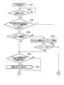
- step S101 the control part 15 continues operation
- step S102 the control unit 15 stands by in a non-charged state until a current flowing through the secondary coil 11 is detected by the current detection circuit 12.
- the control unit 15 advances the process to step S103.
- step S103 the control unit 15 reads the operation setting at the time of an incoming call set in advance by the user.
- the control unit 15 advances the process to step S104.
- the control unit 15 advances the process to step S117 (see FIG. 4).
- step S104 the control unit 15 verifies whether or not there is a Bluetooth (registered trademark) communication device 3 (a Bluetooth (registered trademark) communication device 3 already connected so as to be communicable) being paired. If there is a Bluetooth (registered trademark) communication device 3 being paired, the control unit 15 advances the process to step S105. On the other hand, if there is no Bluetooth (registered trademark) communication device 3 being paired, the control unit 15 advances the process to step S107.
- a Bluetooth (registered trademark) communication device 3 a Bluetooth (registered trademark) communication device 3 already connected so as to be communicable
- step S105 the control unit 15 reads the settings related to the LCD display unit 17 when the Bluetooth (registered trademark) device is used.
- the control unit 15 verifies whether or not the display on the LCD display unit 17 is set to be OFF (display stop). If the setting is to turn off the display on the LCD display unit 17, the control unit 15 advances the process to step S106. On the other hand, when it is not the setting which should turn OFF the display of the LCD display part 17, the control part 15 advances a process to step S109 (refer FIG. 3).
- step S106 the control unit 15 turns off the display on the LCD display unit 17, and advances the process to step S109 (see FIG. 3).
- step S107 the control unit 15 starts pairing with a preset Bluetooth (registered trademark) device (here, Bluetooth (registered trademark) communication device 3) via the Bluetooth (registered trademark) communication circuit 16. .
- step S ⁇ b> 108 the control unit 15 verifies whether pairing with the Bluetooth (registered trademark) communication device 3 is successful. If the pairing with the Bluetooth (registered trademark) communication device 3 is successful, the control unit 15 advances the process to step S105. On the other hand, if the pairing with the Bluetooth (registered trademark) communication device 3 is unsuccessful, the control unit 15 advances the process to step S117 (see FIG. 4).
- step S109 the control unit 15 continues the operation in the non-contact charging state during use of the Bluetooth (registered trademark) communication device 3.
- step S ⁇ b> 110 the control unit 15 waits until there is an incoming call from another device via the transmission / reception circuit 10. If there is an incoming call from another device via the transmission / reception circuit 10, the control unit 15 advances the process to step S111.
- step S ⁇ b> 111 the control unit 15 notifies the Bluetooth (registered trademark) communication device 3 through the Bluetooth (registered trademark) communication circuit 16 that an incoming call has been received.
- step S112 the control unit 15 verifies whether or not the Bluetooth (registered trademark) communication device 3 has a function of notifying the user of the caller information.
- the control unit 15 advances the process to step S113.
- the control unit 15 transmits incoming caller information to the Bluetooth (registered trademark) communication device 3 via the Bluetooth (registered trademark) communication circuit 16, and displays the caller information on the display unit 31.
- step S ⁇ b> 114 the control unit 15 waits until the user presses the reception button of the Bluetooth (registered trademark) communication device 3. When the reception button is pressed, control unit 15 advances the process to step S115.
- step S115 the control unit 15 controls the state of a call via the Bluetooth (registered trademark) communication device 3 between the recipient and the user in the incoming call described above.
- step S ⁇ b> 116 the control unit 15 determines that the user has pressed the reception button of the Bluetooth (registered trademark) communication device 3 again via the Bluetooth (registered trademark) communication device 3, or the incoming call described above via the transmission / reception circuit 10. It is detected that the call of the called party at is ended. And the control part 15 complete
- step S117 the control unit 15 continues the operation in the non-contact charging state in which the Bluetooth (registered trademark) communication device 3 is not used.
- step S ⁇ b> 118 the control unit 15 waits for an incoming call from another device via the transmission / reception circuit 10. When there is an incoming call from another device via the transmission / reception circuit 10, the control unit 15 advances the process to step S119.
- step S119 the control unit 15 waits until the reception button on the apparatus main body is pressed. When the user presses the reception button, the control unit 15 advances the process to step S120.
- step S120 the control unit 15 verifies whether or not a charging current flowing through the secondary coil 11 is detected by the current detection circuit 12. When the charging current is detected, the control unit 15 advances the process to step S121. If the charging current is not detected, the control unit 15 advances the process to step S123. In step S121, the fact that the charging current flowing through the secondary coil 11 is detected by the current detection circuit 12 in the control unit 15 means that the secondary battery 13 is in an uncharged state (a state where charging is not completed). Therefore, it is determined that the amount of power that can be used is not secured.
- control unit 15 instructs the user to make a call with the above-described hands-free function (that is, a call in a state where the apparatus main body is placed on the charging pad 2), and until the termination condition is satisfied in step S122. Control the call state.
- step S122 the control unit 15 detects that the reception button on the apparatus main body has been pressed again by the user, or confirms that the call of the called party in the above-described incoming call is ended through the transmission / reception circuit 10. Detect and end call state control. Thereafter, the control unit 15 returns the process to step S117.
- step S123 the control unit 15 indicates that the charging current flowing through the secondary coil 11 is not detected by the current detection circuit 12, that the secondary battery 13 is in a fully charged state (a state in which charging is completed) and is used. Judge that the amount of power available is secured. Then, the control unit 15 instructs the user to perform a normal call (that is, a call with the apparatus main body removed from the charging pad 2), and controls the call state until a termination condition is satisfied in step S122. .
- a normal call that is, a call with the apparatus main body removed from the charging pad 2
- step S120 it was verified whether or not the charging current flowing through the secondary coil 11 was detected by the current detection circuit 12 in order to determine the full charge state in step S120.
- a method of detecting the voltage value of the voltage detection circuit 14 may be used for the determination of the fully charged state in step S120.
- FIG. 5 is a flowchart showing operations from the non-contact charging state to the charging completion state of the mobile terminal device 1 in the charging system for the mobile terminal device according to the embodiment of the present invention.
- the control unit 15 continues the non-contact charging state due to the charging current flowing through the secondary coil 11.
- the control unit 15 continues the non-contact charging state in step S201 until the secondary battery 13 is fully charged while checking the output voltage value of the secondary battery 13 detected by the voltage detection circuit 14. .
- the control unit 15 advances the process to step S203.
- step S203 the control unit 15 verifies the existence of the Bluetooth (registered trademark) communication device 3 being paired. If there is a Bluetooth (registered trademark) communication device 3 being paired, the control unit 15 advances the processing to step S204. On the other hand, when there is no Bluetooth (registered trademark) communication device 3 being paired, the control unit 15 advances the processing to step S206. In step S204, the control unit 15 notifies the Bluetooth (registered trademark) communication device 3 that the secondary battery 13 is fully charged via the Bluetooth (registered trademark) communication circuit 16, and displays the notification. Output to the unit 31. Then, the control part 15 advances a process to step S205. Thereby, the user can know that the secondary battery 13 is in a fully charged state by the display screen of the display unit 31, the notification sound, the vibration of the vibrator, and the like.
- step S205 the control unit 15 completes the non-contact charging state and maintains the state after completion.
- step S206 the control unit 15 notifies the user that the secondary battery 13 has been fully charged via the LCD display unit 17 of the apparatus main body. Then, the control part 15 advances a process to step S205.
- FIG. 6 is a flowchart showing operations from the abnormal charging stop of the portable terminal device 1 to the return of the charged state in the charging system for the portable terminal device according to the embodiment of the present invention.
- the operation from the abnormal charging stop of the mobile terminal device 1 to the return of the charging state in the mobile terminal device charging system according to the present embodiment will be described using the flowchart shown in FIG. 6 with reference to FIG. .
- step S ⁇ b> 301 the control unit 15 continues the non-contact charging state due to the charging current flowing through the secondary coil 11.
- step S302 the control unit 15 checks the output value of the current detection circuit 12, whereby the current flowing through the secondary coil 11 is cut off and the secondary battery 13 is not yet fully charged (non-contact charging). Is detected to have stopped abnormally).
- step S303 the control unit 15 verifies the existence of the Bluetooth (registered trademark) communication device 3 during pairing. If there is a Bluetooth (registered trademark) communication device 3 being paired, the control unit 15 advances the processing to step S304. On the other hand, when there is no Bluetooth (registered trademark) communication device 3 being paired, the control unit 15 advances the processing to step S307.
- step S304 the control unit 15 notifies the Bluetooth (registered trademark) communication device 3 that the charging of the secondary battery 13 has been stopped via the Bluetooth (registered trademark) communication circuit 16, and the display unit 31 notifies the notification. To output. Then, the control part 15 advances a process to step S305. Thereby, the user can know that the charging of the secondary battery 13 has been stopped by the display screen of the display unit 31, the notification sound, the vibration of the vibrator, and the like.
- step S305 the control unit 15 verifies whether or not the apparatus main body is again placed on the charging pad 2 by the user operation (that is, whether or not the apparatus main body is returned to the non-contact charging state).
- step S306 the control unit 15 advances the process to step S308.
- step S306 the control unit 15 maintains the non-contact charging state.
- step S307 the control unit 15 notifies the user that charging of the secondary battery 13 is stopped via the LCD display unit 17 of the apparatus main body, and then the control unit 15 advances the process to step S305.
- step S308 the control unit 15 maintains an incomplete state of non-contact charging.
- the Bluetooth (registered trademark) communication device 3 is used. Voice call can be started in a state where the non-contact charging state is maintained.
- a program for causing a computer to execute the above processing may be distributed by storing it in a computer-readable recording medium such as a semiconductor memory or a CD-ROM.
- a computer including at least a microcomputer, a personal computer, and a general-purpose computer may read the program from the recording medium and execute the processing.
- Local communication is performed between a portable terminal device including a secondary battery and a control unit, a charging pad that supplies power for charging the secondary battery in a contactless manner, and the portable terminal device.
- the portable terminal device is designated to use the communication device, and communication between the portable terminal device and the communication device is possible.
- the incoming call is transferred from the mobile terminal device to the communication device, and a user of the mobile terminal device is passed through the communication device.
- the control unit determines that communication between the mobile terminal device and the communication device is possible, and the control The unit starts pairing between the mobile terminal device and the communication device when there is no communication device being paired with the mobile terminal device, and when the pairing is successful,
- the charging system for a portable terminal device according to supplementary note 1, wherein it is determined that communication with the communication device is possible.
- the mobile terminal device further includes a display unit.
- the control unit stops the operation of the display unit when designation is made to not operate the display unit when the communication device is used.
- the communication device includes a notification unit for the user, and the incoming call is transferred from the mobile terminal device.
- the said control part is in the state in which the specification which should use the said communication apparatus is not set to the said portable terminal device, or the communication between the said portable terminal device and the said communication apparatus is impossible, Item 2.
- the supplementary note 1 wherein when the mobile terminal device receives an incoming call during the charging of the mobile terminal device, the user of the mobile terminal device makes a call with the caller of the incoming call through the mobile terminal device.
- the said portable terminal device is further provided with the display part and the detection part which grasps
- the said control part is in the said portable terminal device during the said charge of the said portable terminal device.
- the said portable terminal device is further provided with the display part and the detection part which measures the output voltage of the said secondary battery, and the said control part is a pair when the said secondary battery becomes a full charge.
- the communication device in the ring exists, the fact that the secondary battery is fully charged is notified to the user via the communication device, and the control unit notifies the user that the secondary battery is fully charged.
- the mobile terminal device according to appendix 1, which notifies the user of the fact that the secondary battery is fully charged via the display unit. Charging system.
- the said portable terminal device is further provided with the detection part which measures the charging current and output voltage of the said secondary battery, and the said control part is the charging current of the said secondary battery cut off And when the output voltage of the secondary battery is less than full charge, if there is the communication device being paired, the user has confirmed that charging of the secondary battery has been stopped via the communication device.
- the control unit is in the case where the communication device being paired does not exist
- the charging system for a portable terminal device according to supplementary note 1 wherein the user is notified through the display unit that charging of the secondary battery has stopped.
- the user is notified of the incoming call and the incoming call content via the transmission / reception unit and the charging status of the secondary battery via the local communication device, and the control unit displays on the display unit.
- a mobile terminal device that does not display the incoming call on the display unit when there is a designation not to execute the call.
- the present invention can be applied to a charging system for a mobile terminal device and a mobile terminal device. According to this charging system, even when there is an incoming voice call while the mobile terminal device is placed on the charging pad and performing non-contact charging, the mobile terminal device is already paired with a local communication device. If it is a state, a voice call can be smoothly started in a state where the non-contact charging state is maintained.
Landscapes
- Engineering & Computer Science (AREA)
- Computer Networks & Wireless Communication (AREA)
- Power Engineering (AREA)
- Human Computer Interaction (AREA)
- Signal Processing (AREA)
- Telephone Function (AREA)
- Charge And Discharge Circuits For Batteries Or The Like (AREA)
Abstract
携帯端末装置の充電システムは、二次電池および制御部を備える携帯端末装置と、前記二次電池を充電する電力を非接触で供給する充電パッドと、前記携帯端末装置との間でローカルな通信を行う通信機器とを備える。前記制御部は、前記携帯端末装置に前記通信機器を使用する指定が設定されていて、しかも前記携帯端末装置と前記通信機器との間の通信が可能な状態で、前記携帯端末装置の前記充電パッドを用いた充電中に前記携帯端末装置に着信があった時には、前記着信を、前記携帯端末装置から前記通信機器に転送し、前記携帯端末装置のユーザには、前記通信機器を介して前記着信の発呼者と通話させる。
Description
本発明は、携帯端末装置の充電システム及び携帯端末装置に関する。特に本発明は、充電パッドから供給される充電電力を携帯端末装置において非接触状態で受電させて、その携帯端末装置の内蔵二次電池を充電することができる携帯端末装置の充電システム及び携帯端末装置に関する。
近年、携帯電話装置等の携帯端末装置においては、非接触充電機能を実現する充電システムが普及している。このシステムにより、ユーザは、携帯端末装置を充電する際に、電力供給用のケーブルを抜き挿しする手間が不要となる。そのため、一見して、充電の利便性は向上しているように思える。しかし、これらの充電システムを用いて充電する二次電池を内蔵した携帯端末装置の充電状態を維持し続ける際に、ユーザは、その携帯端末装置を手に保持して操作しながら、その携帯端末装置の機能を使用することができない。よって、この一点においては、非接触の充電システムは、これまでのACアダプタを用いた接触型の充電システムと比較すると不便である。携帯端末装置は、バッテリーを搭載している限りは、そのバッテリーを充電して使用するという使用形態が避けられない。しかしながら、このバッテリー充電の必要性が存在することによって携帯端末装置の操作が制限されてしまって、本来の使用形態(手に保持した状態での使用)が禁止となるのであれば、ユーザにとって完全に利便性が向上したとは言えない。
ユーザが携帯端末装置の存在位置から距離的に離れた場合にも解決を要する課題がある。例えば、非接触充電中は、携帯端末装置を充電パッドに置いているだけの状態である。よって、第三者の介入等によってその携帯端末装置が充電パッドから外されてしまったような場合には、簡単に充電が停止してしまう。携帯端末装置の表示部の表示画面を上側に向けた状態で充電パッドに載置するタイプの機種は、一般家庭や公共の場において、その表示画面を第三者に見られてしまう。そのため、その携帯端末装置のユーザのプライバシーが損なわれる場合があり得る。このため、何らかの方法によって、これらの課題を解決し、非接触充電システムの利便性をより一層向上させることが望まれている。
この分野の公知技術としては、例えば、特許文献1には、二次電池を効率良く非接触で充電する技術が開示されている。具体的には、プラグが商用電源コンセントに接続されたとき、周波数変換回路は、商用周波数の電源電力を3個の並列共振回路に等しい所定の周波数の変換電力に変換する。受電部の3個の並列共振回路は、送電部の送信手段からの電力を受信する受信手段として働く。受電部の2個の整流回路は、受信手段の出力を直流電力に変換する。特許文献2には、ハンドフリー通話機能を有する充電用置台が開示されている。この構成により、ヘッドホンの装着や電源の心配をなくし、携帯電話機を手間なく使用することができる。具体的には、充電用載置台に設けたスピーカとマイクロホンとを用いたハンドフリー回路により、携帯電話機のハンドフリー通話を可能にする構成としている。
特許文献3には、複数の装置の間の無線接続を簡単に行うことができる無線機器接続システムが開示されている。具体的には、第1制御部を備えた第1の端末装置と、第2無線接続インタフェース及びこのインタフェースを起動する第2制御部を備えた第2の端末装置とから成る無線機器接続システムを開示している。この第2の端末装置は、第1の端末装置がセットされたことを検出してセット信号を出力する検出器を備えたホルダを備える。第2の端末装置の第2制御部は、検出器から送られてくるセット信号に応答して第2無線接続インタフェースを起動し、第1の端末装置と第2の端末装置との間の無線接続を確立する。
特許文献4には、発呼及びメールを着信した時に、発信者情報を表示する機能を持った通信端末装置が、第3者に着信表示を見られることによる情報漏洩を防止する機能を有する構成が開示されている。具体的には、秘匿表示を行う条件と、発信者識別用のマーク等を予め記憶部に設定しておく。そして、通信端末装置が秘匿表示条件を満たした着信を受けると、記憶部に記憶された秘匿者設定情報または秘匿設定されたアドレス帳に登録した発信者情報の代わりに、マーク等を用いた秘匿表示によって着信を知らせる。この秘匿表示を解除する操作がなされた場合は、通常の着信通知に表示が切り替えられる。
例えば、電磁誘導方式を採用した非接触充電システムは、特許文献1にも示されているように、送電側の一次コイルと、受電側の装置に搭載された二次コイルの間の、磁界結合による誘導電流でもって電力送電を実施する仕組みを有している。このため、充電される携帯端末装置が非接触充電システムの充電器から外された場合、コイル間の磁界結合が消失する。結果として充電を停止させてしまう。より具体的には、公知の非接触充電システムを用いた充電を携帯端末装置に対して実施した場合、以下の項目(1)~(3)に示す問題点があった。
項目(1):音声着信により非接触充電が中断してしまう(例えば特許文献1,3,4)。
例えば、電話等の通信機能を有する携帯端末装置が、この非接触充電を行う場合を想定する。この場合、充電中に音声着信等があった場合、ユーザは、携帯端末装置を充電パッドから外して通話しなければならない。このため、充電を停止させてしまう。電池残量が少ない状態で携帯端末装置を充電パッドから外してしまうと、他の場面での通話中や操作中に、内蔵の電池が切れてしまって、該携帯端末装置を使用できなくなる局面が到来することもあり得る。その場合、携帯端末装置の使用が著しく制限されてしまうことになる。特許文献2に記載の技術は、この問題点を一応は回避できているが、ハンドフリー状態での通話を強いられるという別の問題点がある。
例えば、電話等の通信機能を有する携帯端末装置が、この非接触充電を行う場合を想定する。この場合、充電中に音声着信等があった場合、ユーザは、携帯端末装置を充電パッドから外して通話しなければならない。このため、充電を停止させてしまう。電池残量が少ない状態で携帯端末装置を充電パッドから外してしまうと、他の場面での通話中や操作中に、内蔵の電池が切れてしまって、該携帯端末装置を使用できなくなる局面が到来することもあり得る。その場合、携帯端末装置の使用が著しく制限されてしまうことになる。特許文献2に記載の技術は、この問題点を一応は回避できているが、ハンドフリー状態での通話を強いられるという別の問題点がある。
項目(2):ユーザが関知しない充電の停止が生じることがある(例えば特許文献1~4)。
ここでは、一般家庭や、公共の場所で携帯端末装置の非接触充電を行う場合を想定する。この場合、携帯端末装置を充電パッドに置いた状態でユーザがその場から離れているときに、何らかの事情(例えば、第三者の手操作の介入や、地震の発生)によって、充電中の携帯端末装置が充電パッドから外れてしまうと、この事態の発生が通知されない。
その場合、ユーザがその事態の発生を発見するまでの間、携帯電話装置は充電が中断したままの状態となってしまう。
ここでは、一般家庭や、公共の場所で携帯端末装置の非接触充電を行う場合を想定する。この場合、携帯端末装置を充電パッドに置いた状態でユーザがその場から離れているときに、何らかの事情(例えば、第三者の手操作の介入や、地震の発生)によって、充電中の携帯端末装置が充電パッドから外れてしまうと、この事態の発生が通知されない。
その場合、ユーザがその事態の発生を発見するまでの間、携帯電話装置は充電が中断したままの状態となってしまう。
項目(3):ユーザのプライバシーが損なわれることがある(例えば特許文献1~3)。
非接触充電システムは、携帯端末装置の二次コイル側を下にして充電パッドに載置しなければならないという制約がある。このため、一般家庭や公共の場所で携帯端末装置の非接触充電を行っている際中に、携帯端末装置に音声信号等の着信があると、携帯端末装置のLCD表示画面等を介して第三者に発信者の名前が見られてしまう事態が避けられない。
この場合はユーザのプライバシーが損なわれてしまう。特許文献4に記載の技術は、この問題点を一応は回避できている。しかしながら、この技術では、携帯端末装置のユーザは、LCD表示画面に表示されるマークの意味を予め熟知していなければならないという不便さが残る。よって、何らかの手段によって、これらの課題を解決し、非接触充電の利便性をより高めることが必要とされていた。
本発明の目的の一例は、上述した課題を解決する携帯端末装置の充電システム及び携帯端末装置を提供するである。
上記課題を解決するために、本発明に係る携帯端末装置の充電システムは、二次電池および制御部を備える携帯端末装置と、二次電池を充電する電力を非接触で供給する充電パッドと、携帯端末装置との間でローカルな通信を行う通信機器とを備える。制御部は、携帯端末装置に通信機器を使用する指定が設定されていて、しかも携帯端末装置と通信機器との間の通信が可能な状態で、携帯端末装置の充電パッドを用いた充電中に携帯端末装置に着信があった時には、着信を、携帯端末装置から通信機器に転送し、携帯端末装置のユーザには、通信機器を介して着信の発呼者と通話させる。
本発明に係る携帯端末装置は、少なくとも携帯電話回線網と通信可能に接続された送受信部と、二次電池を充電する充電部と、二次電池の充電状況を検知する検知部と、情報を表示する表示部と、外部のローカルな通信機器との通信を行うローカル通信部と、制御部とを備える。制御部は、二次電池の充電時に、ローカルな通信機器と通信可能に接続されている場合は、送受信部を介しての着信及び着信内容と、二次電池の充電状況とを、ローカルな通信機器を介してユーザに通知する。制御部は、表示部への表示を実施させない指定がある場合は着信の表示部での表示を実施しないように制御する。
本発明によれば、携帯端末装置を充電パッドに載置して非接触充電を行っている間に、音声着信があった場合にも、携帯端末装置がローカルな通信機器とペアリング済みの状態であれば、非接触充電状態を保った状態で、スムーズに音声通話を開始することができる。
以下、本発明の携帯端末装置の充電システム及び携帯端末装置の実施形態について、図面を参照して詳細に説明する。図1は、本発明の実施形態に係る携帯端末装置の充電システムの全体構成を示す構成図である。本実施形態の携帯端末装置の充電システムは、携帯端末装置1、充電パッド2、及びBluetooth(登録商標)通信機器3(ローカル通信部)を備える。充電パッド2は、携帯端末装置1に充電用電力を供給する。Bluetooth(登録商標)通信機器3は、携帯端末装置1との間でBluetooth(登録商標)通信規格に準拠した通信を行う。
携帯端末装置1は、送受信回路10(送受信部)、二次コイル11(充電部)、電流検出回路12(検知部)、二次電池13、電圧検出回路14(検知部)、制御部15、Bluetooth(登録商標)通信回路16、及びLCD表示部17(表示部)を備える。送受信回路10は、他装置との情報の送受信を行う。二次コイル11は、充電用電力を受電する。電流検出回路12は、二次コイル11を流れる充電電流を検出する。電圧検出回路14は、二次電池13の電圧値を検出する。制御部15は、回路状態を判断して装置全体の動作を制御する。Bluetooth(登録商標)通信回路16は、Bluetooth(登録商標)通信機器3との間でBluetooth(登録商標)通信規格に準拠した通信を行う。この他に、携帯端末装置1は、各種情報処理部等の、一般的な携帯端末装置としての構成要素を備えていても良い。
携帯端末装置1は、具体的には携帯電話装置、携帯情報端末装置、携帯ゲーム機器等であって良い。
携帯端末装置1は、具体的には携帯電話装置、携帯情報端末装置、携帯ゲーム機器等であって良い。
充電パッド2は、この実施形態では携帯端末装置1を載置できる構成を有する。しかしながら、充電パッド2は、充電用の一次コイルを備えて、携帯端末装置1が備える二次コイル11に充電電流を励起できる構成でありさえすれば良い。充電パッド2の形状や詳細構成は限定されない。Bluetooth(登録商標)通信機器3は、少なくとも表示部(報知部)31を備える。この表示部31は、LCD等を用いた表示装置による映像表示機能の他、スピーカやヘッドホン等による音声出力機能や、バイブレータによるバイブレーション機能を有していても良い。ローカル通信部は、この実施形態ではBluetooth(登録商標)規格に準拠した通信機能を備えた機器である。しかしながら、ローカル通信部は、任意のLAN通信規格の通信機能を備えたローカルな通信機器(有線/無線を問わない)であっても良い。
以下、上記のシステム構成において、携帯端末装置1が充電パッド2に載置されたのと同時に、二次コイル11に充電電流が流れ、二次電池13への充電が開始されている場合について説明する(非接触(無接点)充電の開始)。以下、ケース1~3別に、本実施形態の携帯端末装置の充電システムが備える機能について説明する。
ケース1は、携帯端末装置1の充電中に音声信号の着信があることを想定した機能である。まず、電流検出回路12は、二次コイル11に充電電流が流れていることを検出する。二次コイル11に充電電流が流れている場合、制御部15は、ペアリング済のBluetooth(登録商標)通信機器3が存在しているか否かを判断する。ペアリング済のBluetooth(登録商標)通信機器3が存在していない場合は、Bluetooth(登録商標)通信回路16がBluetooth(登録商標)通信機器3とのペアリングを行う。この後、音声着信があった場合には、Bluetooth(登録商標)通信機器3とはペアリング済みの状態である。このため、携帯端末装置1を充電パッドに置いたままの状態で、Bluetooth(登録商標)通信機器3を介してスムーズに音声通話を開始することができる。Bluetooth(登録商標)通信機器3を使用しないか、若しくはBluetooth(登録商標)通信機器3が使用できない場合には、制御部15は、装置本体を充電パッドに載置した状態での装置本体を使用した通話(即ちハンズフリー機能の通話)に切り替える。このようにして、携帯端末装置1のユーザは、この場合においても音声通話を行うことができる。
ケース2は、携帯端末装置1の充電中に、ユーザが関知しない充電停止が生じることを想定した機能である。即ち、携帯端末装置1が、充電中に充電パッド2から外れ、充電が停止した場合を想定する。携帯端末装置1が、充電中に充電パッド2から外れると、二次コイル11に充電電流が流れなくなる。このため、電流検出回路12が、この充電停止状態を検出する。
これを受けて、Bluetooth(登録商標)通信回路16は、この充電停止状態の旨を、Bluetooth(登録商標)通信機器3の表示部31等を介してユーザに報知する。これにより、ユーザは充電が停止したことに気づく。ユーザの手操作によって携帯端末装置1を元の非接触充電状態に復帰させて、充電完了まで非接触充電状態を維持させ続けることができる。
これを受けて、Bluetooth(登録商標)通信回路16は、この充電停止状態の旨を、Bluetooth(登録商標)通信機器3の表示部31等を介してユーザに報知する。これにより、ユーザは充電が停止したことに気づく。ユーザの手操作によって携帯端末装置1を元の非接触充電状態に復帰させて、充電完了まで非接触充電状態を維持させ続けることができる。
ケース3は、ユーザのプライバシーが損なわれることに対処することができる機能である。Bluetooth(登録商標)通信機器3と通信可能状態において携帯端末装置1に着信等があった場合、前述の非接触充電中に限り、携帯端末装置1の本体での報知を停止する(より具体的には、LCD表示部17の表示をOFFにする)。この着信の事実及び着信内容等は、Bluetooth(登録商標)通信機器3にのみ報知されることになる。これにより、携帯端末装置1のユーザが、携帯端末装置1の設置場所(即ち充電パッド2の設置場所)から距離的に遠く離れた場所居る場合であっても、そのユーザのみが、着信内容等を知ることができる。その結果、携帯端末装置1のユーザのプライバシーを保つことができる。
図2~4は、本発明の実施形態に係る携帯端末装置の充電システムにおける、携帯端末装置1の非充電状態から非接触充電状態及び通話状態までの動作を示すフローチャート図である。まず、図1を参照しながら、図2に示す動作について説明する。ステップS101では、制御部15は、充電状態ではない場合の動作を継続する。ステップS102では、制御部15は、電流検出回路12によって二次コイルに11に流れる電流が検出されるまで非充電状態のままで待機する。一方、電流検出回路12が、二次コイルに11に流れる電流を検出すると制御部15は処理をステップS103に進める。
ステップS103では、制御部15が、ユーザによって予め設定されている着信時の動作設定を読み出する。読み出した動作設定が、「Bluetooth(登録商標)機器使用」である場合、制御部15は処理をステップS104に進める。一方、読み出した動作設定が「ハンズフリー」であるか若しくは設定無しの場合、制御部15は処理をステップS117(図4参照)に進める。ステップS104では、制御部15が、ペアリング中のBluetooth(登録商標)通信機器3(通信可能に既接続されているBluetooth(登録商標)通信機器3)が存在するか否かを検証する。ペアリング中のBluetooth(登録商標)通信機器3が存在する場合、制御部15は処理をステップS105に進める。一方、ペアリング中のBluetooth(登録商標)通信機器3が存在しない場合、制御部15は処理をステップS107に進める。
ステップS105では、制御部15が、Bluetooth(登録商標)機器使用時のLCD表示部17に関する設定を読み出す。制御部15は、LCD表示部17の表示をOFF(表示停止)にすべき設定か否かを検証する。LCD表示部17の表示をOFFにすべき設定の場合、制御部15は処理をステップS106に進める。一方、LCD表示部17の表示をOFFにすべき設定ではない場合、制御部15は処理をステップS109(図3参照)に進める。ステップS106では、制御部15が、LCD表示部17の表示をOFFにし、処理をステップS109(図3参照)に進める。
ステップS107では、制御部15が、Bluetooth(登録商標)通信回路16を介して、予め設定されたBluetooth(登録商標)機器(ここではBluetooth(登録商標)通信機器3)とのペアリングを開始する。ステップS108では、制御部15が、Bluetooth(登録商標)通信機器3とのペアリングが成功したか否かを検証する。Bluetooth(登録商標)通信機器3とのペアリングが成功した場合、制御部15は処理をステップS105に進める。一方、Bluetooth(登録商標)通信機器3とのペアリングが不成功であった場合、制御部15は処理をステップS117(図4参照)に進める。
次に、図1を参照しながら、図3に示す動作について説明する。ステップS109では、制御部15が、Bluetooth(登録商標)通信機器3使用中の非接触充電状態での動作を継続する。ステップS110では、制御部15が、送受信回路10を介して他装置からの着信があるまで待機する。送受信回路10を介して他装置からの着信があった場合、制御部15は処理をステップS111に進める。ステップS111では、制御部15が、着信があったことを、Bluetooth(登録商標)通信回路16を介して、Bluetooth(登録商標)通信機器3に通知する。
ステップS112では、制御部15が、Bluetooth(登録商標)通信機器3に発信者情報をユーザに通知する機能があるか否かを検証する。Bluetooth(登録商標)通信機器3に発信者情報をユーザに通知する機能がある場合、制御部15は処理をステップS113に進める。一方、Bluetooth(登録商標)通信機器3に発信者情報をユーザに通知する機能が無い場合、制御部15は処理をステップS114に進める。ステップS113では、制御部15が、着信の発信者情報を、Bluetooth(登録商標)通信回路16を介して、Bluetooth(登録商標)通信機器3に送信し、その発信者情報を表示部31に表示させる。その後、制御部15は処理をステップS114に進める。ステップS114では、制御部15が、Bluetooth(登録商標)通信機器3の受話ボタンがユーザによって押下されるまで待機する。受話ボタンが押下されると制御部15は処理をステップS115に進める。
ステップS115では、制御部15が、前述の着信における着信者とユーザとの間の、Bluetooth(登録商標)通信機器3を介した通話状態を制御する。ステップS116では、制御部15が、Bluetooth(登録商標)通信機器3を介してBluetooth(登録商標)通信機器3の受話ボタンがユーザによって再び押下されたこと、又は送受信回路10を介して前述の着信における着信者の通話が終話となったことを検知する。そして、制御部15は通話状態の制御を終了し、その後、処理をステップS109に戻す。
次に、図1を参照しながら、図4に示す動作について説明する。ステップS117では、制御部15が、Bluetooth(登録商標)通信機器3未使用の非接触充電状態での動作を継続する。ステップS118では、制御部15が、送受信回路10を介して他装置からの着信があるまで待機する。送受信回路10を介して他装置からの着信があった場合、制御部15は処理をステップS119に進める。ステップS119では、制御部15が、装置本体の受話ボタンが押下されるまで待機する。受話ボタンがユーザにより押下されると制御部15は処理をステップS120に進める。
ステップS120では、制御部15は、電流検出回路12によって二次コイル11に流れる充電電流が検出されているか否かを検証する。充電電流が検出されている場合、制御部15は処理をステップS121に進める。また、充電電流が検出されていない場合、制御部15は処理をステップS123に進める。ステップS121では、制御部15は、電流検出回路12によって二次コイル11に流れる充電電流が検出されているということは、二次電池13が未充電状態(充電が完了していない状態)であり、使用可能な電力量は確保されていないと判断する。そして、制御部15は、ユーザに、前述のハンズフリー機能での通話(即ち、装置本体を充電パッド2に載置した状態での通話)を指示すると共に、ステップS122で終了条件となるまで、その通話状態を制御する。
ステップS122では、制御部15が、装置本体の受話ボタンがユーザによって再び押下されたことを検知するか、若しくは送受信回路10を介して前述の着信における着信者の通話が終話となったことを検知して、通話状態の制御を終了する。その後、制御部15は処理をステップS117に戻す。ステップS123では、制御部15は、電流検出回路12によって二次コイル11を流れる充電電流が検出されていないということは、二次電池13が満充電状態(充電が完了した状態)であり、使用可能な電力量は確保されていると判断する。そして、制御部15は、ユーザに、通常の通話(即ち、装置本体を充電パッド2から外した状態での通話)を指示すると共に、ステップS122で終了条件となるまで、その通話状態を制御する。
この動作説明では、ステップS120での満充電状態の判定を行うために、電流検出回路12によって二次コイル11に流れる充電電流が検出されているか否かを検証した。しかしながら、ステップS120での満充電状態の判定には、電圧検出回路14の電圧値を検出する方法を用いても良い。
図5は、本発明の実施形態に係る携帯端末装置の充電システムにおける、携帯端末装置1の非接触充電状態から充電完了状態までの動作を示すフローチャート図である。以下、図1を参照しながら、図5に示すフローチャートを使用して、本実施形態に係る携帯端末装置の充電システムにおける、携帯端末装置1の非接触充電状態から充電完了状態までの動作について説明する。ステップS201では、制御部15は、二次コイル11に流れる充電電流による非接触充電状態を継続する。ステップS202では、制御部15は、電圧検出回路14が検出する二次電池13の出力電圧値をチェックしながら、二次電池13が満充電状態となるまでステップS201の非接触充電状態を継続する。二次電池13が満充電状態となると制御部15は処理をステップS203に進める。
ステップS203では、制御部15は、ペアリング中のBluetooth(登録商標)通信機器3の存在を検証する。ペアリング中のBluetooth(登録商標)通信機器3が存在する場合、制御部15は処理をステップS204に進める。一方、ペアリング中のBluetooth(登録商標)通信機器3が存在しない場合、制御部15は処理をステップS206に進める。ステップS204では、制御部15は、Bluetooth(登録商標)通信回路16を介して、二次電池13が満充電状態となったことをBluetooth(登録商標)通信機器3に通知し、その通知を表示部31に出力させる。その後、制御部15は処理をステップS205に進める。これにより、ユーザは、表示部31の表示画面、報知音、バイブレータのバイブレーション等により、二次電池13が満充電状態となったことを知ることができる。
ステップS205では、制御部15は、非接触充電状態を完了し、完了後の状態を維持する。
ステップS206では、制御部15は、装置本体のLCD表示部17等を介して、二次電池13が満充電状態となったことをユーザに通知する。その後、制御部15は処理をステップS205に進める。図6は、本発明の実施形態に係る携帯端末装置の充電システムにおける、携帯端末装置1の充電異常停止から充電状態復帰までの動作を示すフローチャート図である。以下、図1を参照しながら、図6に示すフローチャートを使用して、本実施形態に係る携帯端末装置の充電システムにおける、携帯端末装置1の充電異常停止から充電状態復帰までの動作について説明する。ステップS301では、制御部15は、二次コイル11に流れる充電電流による非接触充電状態を継続する。
ステップS206では、制御部15は、装置本体のLCD表示部17等を介して、二次電池13が満充電状態となったことをユーザに通知する。その後、制御部15は処理をステップS205に進める。図6は、本発明の実施形態に係る携帯端末装置の充電システムにおける、携帯端末装置1の充電異常停止から充電状態復帰までの動作を示すフローチャート図である。以下、図1を参照しながら、図6に示すフローチャートを使用して、本実施形態に係る携帯端末装置の充電システムにおける、携帯端末装置1の充電異常停止から充電状態復帰までの動作について説明する。ステップS301では、制御部15は、二次コイル11に流れる充電電流による非接触充電状態を継続する。
ステップS302では、制御部15は、電流検出回路12の出力値をチェックすることにより、二次コイル11に流れる電流が絶たれ、かつ二次電池13が未だ満充電状態で無いこと(非接触充電が異常停止したこと)を検知する。ステップS303では、制御部15は、ペアリング中のBluetooth(登録商標)通信機器3の存在を検証する。ペアリング中のBluetooth(登録商標)通信機器3が存在する場合、制御部15は処理をステップS304に進める。一方、ペアリング中のBluetooth(登録商標)通信機器3が存在しない場合、制御部15は処理をステップS307に進める。
ステップS304では、制御部15は、Bluetooth(登録商標)通信回路16を介して、二次電池13の充電が停止したことをBluetooth(登録商標)通信機器3に通知し、その通知を表示部31に出力させる。その後、制御部15は処理をステップS305に進める。これにより、ユーザは、表示部31の表示画面、報知音、バイブレータのバイブレーション等により、二次電池13の充電が停止となったことを知ることができる。ステップS305では、制御部15は、ユーザ操作により、装置本体が再び充電パッド2に載置されたか否か(即ち、非接触充電状態に復帰したか否か)を検証する。この検証は、制御部15が電流検出回路12の出力値をチェックして二次コイル11に流れる電流が復元したことを確認することにより行われる。装置本体が再び充電パッド2に載置された場合、制御部15は処理をステップS306に進める。一方、装置本体が未だ充電パッド2に載置されていない場合、制御部15は処理をステップS308に進める。
ステップS306では、制御部15は、非接触充電状態を維持する。ステップS307では、制御部15は、装置本体のLCD表示部17等を介して、二次電池13の充電が停止したことをユーザに通知するその後、制御部15は処理をステップS305に進める。ステップS308では、制御部15は、非接触充電の未完了状態を維持する。本実施形態によれば、携帯端末装置1を充電パッド2に載置して非接触充電を行っている場合に、携帯端末装置1に音声着信があっても、Bluetooth(登録商標)通信機器3とペアリング済みの状態であれば、非接触充電状態を保った状態で、音声通話を開始できる。
また、第三者の手操作、あるいは地震等の、何らかの事情によって充電が停止してしまった場合は、装置本体のLCD表示部17またはBluetooth(登録商標)通信機器3の表示部31を介してユーザに通知する。この場合は、ユーザが装置本体を再び充電パッド2に載置することにより、充電完了まで非接触充電状態を保つことができる。更に、装置本体を充電パッドに載置した状態で離席している間に着信等があると、第三者に着信相手が見えてしまってユーザのプライバシーが保たれなくなるという問題点を、非接触充電中にはBluetooth(登録商標)通信機器3にのみ着信を報知することで解決できる。
携帯端末装置1の構成要素の処理の少なくとも一部をコンピュータ制御により実行してもよい。また、上記処理をコンピュータに実行させるプログラムは、半導体メモリや、CD-ROM等のコンピュータ読み取り可能な記録媒体に格納して配付してもよい。そして、少なくともマイクロコンピュータ、パーソナルコンピュータ、汎用コンピュータを範疇に含むコンピュータが、上記の記録媒体から上記プログラムを読み出して、上記の処理を実行してもよい。
以上、実施形態を参照して本願発明を説明したが、本願発明は上記実施形態に限定されない。本願発明の構成や詳細には、本願発明のスコープ内で当業者が理解し得る様々な変更をすることができる。
以上、実施形態を参照して本願発明を説明したが、本願発明は上記実施形態に限定されない。本願発明の構成や詳細には、本願発明のスコープ内で当業者が理解し得る様々な変更をすることができる。
上記の実施形態の一部、又は全部は、以下の付記のようにも記載され得るが、以下には限られない。
(付記1)二次電池および制御部を備える携帯端末装置と、前記二次電池を充電する電力を非接触で供給する充電パッドと、前記携帯端末装置との間でローカルな通信を行うことができる通信機器とを備え、前記携帯端末装置に前記通信機器を使用する指定が設定されていて、しかも前記携帯端末装置と前記通信機器との間の通信が可能な状態で、前記携帯端末装置の前記充電パッドを用いた充電中に前記携帯端末装置に着信があった時には、前記着信を、前記携帯端末装置から前記通信機器に転送し、前記携帯端末装置のユーザには、前記通信機器を介して前記着信の発呼者と通話させる携帯端末装置の充電システム。
(付記2)前記制御部は、前記携帯端末装置とペアリング中の前記通信機器が存在する場合は、前記携帯端末装置と前記通信機器との間の通信が可能な状態と判断し、前記制御部は、前記携帯端末装置とペアリング中の通信機器が存在しない場合は、前記携帯端末装置と前記通信機器とのペアリングを開始し、前記ペアリングが成功した場合に、前記携帯端末装置と前記通信機器との間の通信が可能な状態であると判断する付記1に記載の携帯端末装置の充電システム。
(付記3)付記1又は2に記載の携帯端末装置の充電システムにおいて、前記携帯端末装置は表示部をさらに備える。前記制御部は、前記通信機器の使用時には前記表示部を作動させない指定が設定されている場合には、前記表示部の動作を停止させる。
(付記4)付記1から3のいずれか一項に記載の携帯端末装置の充電システムにおいて、前記通信機器は、前記ユーザへの報知部を備え、前記携帯端末装置から前記着信が転送された際には、該転送された着信内容を前記報知部を介してユーザに報知する付記1から3のいずれか一項に記載の携帯端末装置の充電システム。
(付記5)前記報知部は、前記携帯端末装置から前記着信が転送された際に、前記転送された着信の発信者情報を、前記ユーザに通知する付記4に記載の携帯端末装置の充電システム。
(付記6)前記制御部は、前記携帯端末装置に前記通信機器を使用すべき指定が設定されていないか、若しくは前記携帯端末装置と前記通信機器との間の通信が不可能な状態で、前記携帯端末装置の前記充電中に前記携帯端末装置に着信があった時には、前記携帯端末装置のユーザには、前記携帯端末装置を介して前記着信の発呼者と通話させる付記1に記載の携帯端末装置の充電システム。
(付記7)前記携帯端末装置は、表示部と、前記二次電池の充電状況を把握する検知部とをさらに備え、前記制御部は、前記携帯端末装置の前記充電中に前記携帯端末装置に着信があった時には、前記二次電池の充電状況に応じて、前記携帯端末装置をユーザが手に保持した状態での通話が可能か、若しくは前記携帯端末装置を前記充電パッドに載置した状態での通話が可能かの、いずれか1つの指示を前記表示部を介して前記ユーザに通知する付記6に記載の携帯端末装置の充電システム。
(付記8)前記携帯端末装置は、表示部と、前記二次電池の出力電圧を測定する検知部とをさらに備え、前記制御部は、前記二次電池が満充電となった場合に、ペアリング中の前記通信機器が存在する場合は該通信機器を介して、前記二次電池が満充電となった事実を前記ユーザに通知し、前記制御部は、前記二次電池が満充電となった場合に、ペアリング中の前記通信機器が存在しない場合には前記表示部を介して、前記二次電池が満充電となった事実を前記ユーザに通知する付記1に記載の携帯端末装置の充電システム。
(付記9)前記携帯端末装置は、表示部と、前記二次電池の充電電流及び出力電圧を測定する検知部とをさらに備え、前記制御部は、前記二次電池の充電電流がカットされて、かつ前記二次電池の出力電圧が満充電に満たない場合に、ペアリング中の前記通信機器が存在する場合は前記通信機器を介して、前記二次電池の充電が停止したことを前記ユーザに通知し、前記制御部は、前記二次電池の充電電流がカットされて、かつ前記二次電池の出力電圧が満充電に満たない場合に、ペアリング中の前記通信機器が存在しない場合には前記表示部を介して、前記二次電池の充電が停止したことを前記ユーザに通知する付記1に記載の携帯端末装置の充電システム。
(付記10)少なくとも携帯電話回線網と通信可能に接続された送受信部と、二次電池を充電する充電部と、前記二次電池の充電状況を検知する検知部と、情報を表示する表示部と、外部のローカルな通信機器との通信を行うローカル通信部と、制御部とを備え、前記制御部は、前記二次電池の充電時に、前記ローカルな通信機器と通信可能に接続されている場合は、前記送受信部を介しての着信及び着信内容と、前記二次電池の充電状況とを、前記ローカルな通信機器を介してユーザに通知し、前記制御部は、前記表示部への表示を実施させない指定がある場合は前記着信の前記表示部での表示を実施しない携帯端末装置。
この出願は、2012年1月13日に出願された日本国特願2012-005109を基礎とする優先権を主張し、その開示の全てをここに取り込む。
本発明は、携帯端末装置の充電システムおよび携帯端末装置に適用することができる。この充電システムによれば、携帯端末装置を充電パッドに載置して非接触充電を行っている間に、音声着信があった場合にも、携帯端末装置がローカルな通信機器とペアリング済みの状態であれば、非接触充電状態を保った状態で、スムーズに音声通話を開始することができる。
1 携帯端末装置
2 充電パッド
3 Bluetooth(登録商標)通信機器
11 二次コイル
12 電流検出回路
13 二次電池
14 電圧検出回路
15 制御部
16 Bluetooth(登録商標)通信回路
17 LCD表示部
31 表示部
2 充電パッド
3 Bluetooth(登録商標)通信機器
11 二次コイル
12 電流検出回路
13 二次電池
14 電圧検出回路
15 制御部
16 Bluetooth(登録商標)通信回路
17 LCD表示部
31 表示部
Claims (10)
- 二次電池および制御部を備える携帯端末装置と、
前記二次電池を充電する電力を非接触で供給する充電パッドと、
前記携帯端末装置との間でローカルな通信を行う通信機器と
を備え、
前記制御部は、前記携帯端末装置に前記通信機器を使用する指定が設定されていて、しかも前記携帯端末装置と前記通信機器との間の通信が可能な状態で、前記携帯端末装置の前記充電パッドを用いた充電中に前記携帯端末装置に着信があった時には、前記着信を、前記携帯端末装置から前記通信機器に転送し、前記携帯端末装置のユーザには、前記通信機器を介して前記着信の発呼者と通話させる
携帯端末装置の充電システム。 - 前記制御部は、前記携帯端末装置とペアリング中の前記通信機器が存在する場合は、前記携帯端末装置と前記通信機器との間の通信が可能な状態と判断し、
前記制御部は、前記携帯端末装置とペアリング中の通信機器が存在しない場合は、前記携帯端末装置と前記通信機器とのペアリングを開始し、前記ペアリングが成功した場合に、前記携帯端末装置と前記通信機器との間の通信が可能な状態であると判断する
請求項1に記載の携帯端末装置の充電システム。 - 前記携帯端末装置は表示部をさらに備え、
前記制御部は、前記通信機器の使用時に前記表示部を作動させない指定が設定されている場合には、前記表示部の動作を停止させる
請求項1又は2に記載の携帯端末装置の充電システム。 - 前記通信機器は、
前記携帯端末装置から前記着信が転送された際には、転送された着信内容をユーザに報知する報知部を備える
請求項1から3のいずれか一項に記載の携帯端末装置の充電システム。 - 前記報知部は、前記携帯端末装置から前記着信が転送された際に、前記転送された着信の発信者情報を、前記ユーザに通知する
請求項4に記載の携帯端末装置の充電システム。 - 前記制御部は、前記携帯端末装置に前記通信機器を使用すべき指定が設定されていないか、若しくは前記携帯端末装置と前記通信機器との間の通信が不可能な状態で、前記携帯端末装置の前記充電中に前記携帯端末装置に着信があった時には、前記携帯端末装置のユーザには、前記携帯端末装置を介して前記着信の発呼者と通話させる
請求項1に記載の携帯端末装置の充電システム。 - 前記携帯端末装置は、
表示部と、
前記二次電池の充電状況を把握する検知部と
をさらに備え、
前記制御部は、前記携帯端末装置の前記充電中に前記携帯端末装置に着信があった時には、前記二次電池の充電状況に応じて、前記携帯端末装置をユーザが手に保持した状態での通話が可能か、若しくは前記携帯端末装置を前記充電パッドに載置した状態での通話が可能かの、いずれか1つの指示を前記表示部を介して前記ユーザに通知する
請求項6に記載の携帯端末装置の充電システム。 - 前記携帯端末装置は、
表示部と、
前記二次電池の出力電圧を測定する検知部と
をさらに備え、
前記制御部は、前記二次電池が満充電となった場合に、ペアリング中の前記通信機器が存在する場合は前記通信機器を介して、前記二次電池が満充電となった事実を前記ユーザに通知し、
前記制御部は、前記二次電池が満充電となった場合に、ペアリング中の前記通信機器が存在しない場合には前記表示部を介して、前記二次電池が満充電となった事実を前記ユーザに通知する
請求項1に記載の携帯端末装置の充電システム。 - 前記携帯端末装置は、
表示部と、
前記二次電池の充電電流及び出力電圧を測定する検知部と
をさらに備え、
前記制御部は、前記二次電池の充電電流がカットされて、かつ前記二次電池の出力電圧が満充電に満たない場合に、ペアリング中の前記通信機器が存在する場合は前記通信機器を介して、前記二次電池の充電が停止したことを前記ユーザに通知し、
前記制御部は、前記二次電池の充電電流がカットされて、かつ前記二次電池の出力電圧が満充電に満たない場合に、ペアリング中の前記通信機器が存在しない場合には前記表示部を介して、前記二次電池の充電が停止したことを前記ユーザに通知する
請求項1に記載の携帯端末装置の充電システム。 - 少なくとも携帯電話回線網と通信可能に接続された送受信部と、
二次電池を充電する充電部と、
前記二次電池の充電状況を検知する検知部と、
情報を表示する表示部と、
外部のローカルな通信機器との通信を行うローカル通信部と、
制御部と
を備え、
前記制御部は、前記二次電池の充電時に、前記ローカルな通信機器と通信可能に接続されている場合は、前記送受信部を介しての着信及び着信内容と、前記二次電池の充電状況とを、前記ローカルな通信機器を介してユーザに通知し、
前記制御部は、前記表示部への表示を実施させない指定がある場合は前記着信の前記表示部での表示を実施しないように制御する
携帯端末装置。
Applications Claiming Priority (2)
| Application Number | Priority Date | Filing Date | Title |
|---|---|---|---|
| JP2012-005109 | 2012-01-13 | ||
| JP2012005109A JP2013145947A (ja) | 2012-01-13 | 2012-01-13 | 携帯端末装置の充電システム及び携帯端末装置 |
Publications (1)
| Publication Number | Publication Date |
|---|---|
| WO2013105461A1 true WO2013105461A1 (ja) | 2013-07-18 |
Family
ID=48781417
Family Applications (1)
| Application Number | Title | Priority Date | Filing Date |
|---|---|---|---|
| PCT/JP2012/084027 Ceased WO2013105461A1 (ja) | 2012-01-13 | 2012-12-28 | 携帯端末装置の充電システム及び携帯端末装置 |
Country Status (2)
| Country | Link |
|---|---|
| JP (1) | JP2013145947A (ja) |
| WO (1) | WO2013105461A1 (ja) |
Families Citing this family (5)
| Publication number | Priority date | Publication date | Assignee | Title |
|---|---|---|---|---|
| KR101558782B1 (ko) | 2014-06-16 | 2015-10-07 | 현대자동차주식회사 | 차량 내 무선 충전상태 알림 장치 및 방법 |
| JP6420641B2 (ja) * | 2014-11-27 | 2018-11-07 | 京セラ株式会社 | 携帯電話 |
| JP6677520B2 (ja) * | 2016-02-09 | 2020-04-08 | キヤノン株式会社 | 情報処理装置、制御方法及びプログラム |
| US11310561B2 (en) | 2016-09-23 | 2022-04-19 | Maxell, Ltd. | Portable terminal device, television receiver, and incoming call notification method |
| KR101922897B1 (ko) * | 2016-11-25 | 2018-11-29 | 에스엘 주식회사 | 차량용 무선 충전 장치의 제어 시스템 및 방법 |
Citations (8)
| Publication number | Priority date | Publication date | Assignee | Title |
|---|---|---|---|---|
| JPH1013528A (ja) * | 1996-06-21 | 1998-01-16 | Matsushita Electric Ind Co Ltd | システムコードレス電話装置 |
| JPH11150881A (ja) * | 1997-11-18 | 1999-06-02 | Nec Corp | 携帯電話用充電器システム |
| JP2002152320A (ja) * | 2000-11-09 | 2002-05-24 | Denso Corp | 電話転送システム |
| JP2006041704A (ja) * | 2004-07-23 | 2006-02-09 | Vodafone Kk | 移動体通信端末、外部リモート装置及びそれらの間の通信方法 |
| JP2008118575A (ja) * | 2006-11-07 | 2008-05-22 | Sony Corp | 通信システム、通信装置、並びに通信装置のための充電器 |
| JP2009124243A (ja) * | 2007-11-12 | 2009-06-04 | Toshiba Corp | 情報処理装置 |
| JP2010259135A (ja) * | 2009-04-21 | 2010-11-11 | Sony Ericsson Mobile Communications Ab | 情報通知システム、充電装置、携帯情報端末、及び、情報通知方法 |
| WO2011024365A1 (ja) * | 2009-08-25 | 2011-03-03 | 日本電気株式会社 | 発信者情報表示方法、携帯電話機、及びプログラムが格納された非一時的なコンピュータ可読媒体 |
Family Cites Families (5)
| Publication number | Priority date | Publication date | Assignee | Title |
|---|---|---|---|---|
| JPH09135849A (ja) * | 1995-11-16 | 1997-05-27 | Dento Shoji:Kk | 歯列矯正装置 |
| US6776614B2 (en) * | 2002-02-13 | 2004-08-17 | Lingualcare, Inc. | Modular system for customized orthodontic appliances |
| JP4150376B2 (ja) * | 2005-01-13 | 2008-09-17 | 裕之 石川 | 歯列矯正用具 |
| ATE468081T1 (de) * | 2006-03-28 | 2010-06-15 | Panasonic Elec Works Co Ltd | Orthodontische vorrichtung |
| JP4356739B2 (ja) * | 2006-11-27 | 2009-11-04 | パナソニック電工株式会社 | 歯列矯正装置 |
-
2012
- 2012-01-13 JP JP2012005109A patent/JP2013145947A/ja active Pending
- 2012-12-28 WO PCT/JP2012/084027 patent/WO2013105461A1/ja not_active Ceased
Patent Citations (8)
| Publication number | Priority date | Publication date | Assignee | Title |
|---|---|---|---|---|
| JPH1013528A (ja) * | 1996-06-21 | 1998-01-16 | Matsushita Electric Ind Co Ltd | システムコードレス電話装置 |
| JPH11150881A (ja) * | 1997-11-18 | 1999-06-02 | Nec Corp | 携帯電話用充電器システム |
| JP2002152320A (ja) * | 2000-11-09 | 2002-05-24 | Denso Corp | 電話転送システム |
| JP2006041704A (ja) * | 2004-07-23 | 2006-02-09 | Vodafone Kk | 移動体通信端末、外部リモート装置及びそれらの間の通信方法 |
| JP2008118575A (ja) * | 2006-11-07 | 2008-05-22 | Sony Corp | 通信システム、通信装置、並びに通信装置のための充電器 |
| JP2009124243A (ja) * | 2007-11-12 | 2009-06-04 | Toshiba Corp | 情報処理装置 |
| JP2010259135A (ja) * | 2009-04-21 | 2010-11-11 | Sony Ericsson Mobile Communications Ab | 情報通知システム、充電装置、携帯情報端末、及び、情報通知方法 |
| WO2011024365A1 (ja) * | 2009-08-25 | 2011-03-03 | 日本電気株式会社 | 発信者情報表示方法、携帯電話機、及びプログラムが格納された非一時的なコンピュータ可読媒体 |
Also Published As
| Publication number | Publication date |
|---|---|
| JP2013145947A (ja) | 2013-07-25 |
Similar Documents
| Publication | Publication Date | Title |
|---|---|---|
| TWI373924B (en) | Apparatuses and methods that facilitate the transfer of power and information among electrical devices | |
| CN102868190B (zh) | 用于电子附件的充电装置 | |
| JP5560609B2 (ja) | 送電制御装置、送電装置、受電制御装置、受電装置及び電子機器 | |
| CN102449989B (zh) | 电话外围单元与接口单元的自动配对 | |
| JP5109905B2 (ja) | 通信装置 | |
| US7574191B2 (en) | Terminal and standby operation control method | |
| TWI607615B (zh) | 無線充電方法及其充電控制器 | |
| WO2013105461A1 (ja) | 携帯端末装置の充電システム及び携帯端末装置 | |
| JP2013110915A (ja) | 充電器、充電制御方法およびプログラム | |
| JP4459159B2 (ja) | 端末装置 | |
| CN102342174A (zh) | 车载终端装置和用于车载终端装置的无线连接程序 | |
| JP2010207074A (ja) | 無接点充電制御システム、無接点充電制御装置および無接点充電制御方法 | |
| CN101257527B (zh) | 无绳电话设备 | |
| EP3007317B1 (en) | Wireless charging method and apparatus for handheld mobile terminal | |
| JP6045518B2 (ja) | 電池残量監視システム、電池残量監視方法、電池残量監視対象装置、電池残量監視プログラム | |
| CN109275058A (zh) | 双模式耳机系统、蓝牙设备和线缆 | |
| JP4293155B2 (ja) | コードレス電話機 | |
| US9479626B2 (en) | System and method for estimating disconnection causes between a base unit and wireless headset and reacting thereto | |
| TWM525019U (zh) | 無線充電系統中的供電裝置及受電裝置及其充電控制器 | |
| CN114448102B (zh) | 耳机盒及无线充电方法、设备、存储介质 | |
| JP4421572B2 (ja) | 電話装置 | |
| CN215186094U (zh) | 无线充电设备及无线充电系统 | |
| JP5909962B2 (ja) | 端末装置と制御方法とプログラム | |
| JP3159164U (ja) | ワイヤレス通信モジュール | |
| JP6571510B2 (ja) | 電話機、および電話機の制御方法 |
Legal Events
| Date | Code | Title | Description |
|---|---|---|---|
| 121 | Ep: the epo has been informed by wipo that ep was designated in this application |
Ref document number: 12865397 Country of ref document: EP Kind code of ref document: A1 |
|
| 122 | Ep: pct application non-entry in european phase |
Ref document number: 12865397 Country of ref document: EP Kind code of ref document: A1 |
|
| NENP | Non-entry into the national phase |
Ref country code: DE |