WO2013105535A1 - Dispositif de pulvérisation électrostatique, et procédé de fabrication de dispositif de film mince organique mettant en œuvre celui-ci - Google Patents
Dispositif de pulvérisation électrostatique, et procédé de fabrication de dispositif de film mince organique mettant en œuvre celui-ci Download PDFInfo
- Publication number
- WO2013105535A1 WO2013105535A1 PCT/JP2013/050059 JP2013050059W WO2013105535A1 WO 2013105535 A1 WO2013105535 A1 WO 2013105535A1 JP 2013050059 W JP2013050059 W JP 2013050059W WO 2013105535 A1 WO2013105535 A1 WO 2013105535A1
- Authority
- WO
- WIPO (PCT)
- Prior art keywords
- thin film
- organic
- organic thin
- electrostatic spray
- coating liquid
- Prior art date
- Legal status (The legal status is an assumption and is not a legal conclusion. Google has not performed a legal analysis and makes no representation as to the accuracy of the status listed.)
- Ceased
Links
Images


Classifications
-
- B—PERFORMING OPERATIONS; TRANSPORTING
- B05—SPRAYING OR ATOMISING IN GENERAL; APPLYING FLUENT MATERIALS TO SURFACES, IN GENERAL
- B05B—SPRAYING APPARATUS; ATOMISING APPARATUS; NOZZLES
- B05B5/00—Electrostatic spraying apparatus; Spraying apparatus with means for charging the spray electrically; Apparatus for spraying liquids or other fluent materials by other electric means
- B05B5/025—Discharge apparatus, e.g. electrostatic spray guns
- B05B5/053—Arrangements for supplying power, e.g. charging power
-
- B—PERFORMING OPERATIONS; TRANSPORTING
- B05—SPRAYING OR ATOMISING IN GENERAL; APPLYING FLUENT MATERIALS TO SURFACES, IN GENERAL
- B05B—SPRAYING APPARATUS; ATOMISING APPARATUS; NOZZLES
- B05B5/00—Electrostatic spraying apparatus; Spraying apparatus with means for charging the spray electrically; Apparatus for spraying liquids or other fluent materials by other electric means
- B05B5/025—Discharge apparatus, e.g. electrostatic spray guns
- B05B5/043—Discharge apparatus, e.g. electrostatic spray guns using induction-charging
-
- B—PERFORMING OPERATIONS; TRANSPORTING
- B05—SPRAYING OR ATOMISING IN GENERAL; APPLYING FLUENT MATERIALS TO SURFACES, IN GENERAL
- B05B—SPRAYING APPARATUS; ATOMISING APPARATUS; NOZZLES
- B05B5/00—Electrostatic spraying apparatus; Spraying apparatus with means for charging the spray electrically; Apparatus for spraying liquids or other fluent materials by other electric means
- B05B5/025—Discharge apparatus, e.g. electrostatic spray guns
- B05B5/047—Discharge apparatus, e.g. electrostatic spray guns using tribo-charging
-
- H—ELECTRICITY
- H10—SEMICONDUCTOR DEVICES; ELECTRIC SOLID-STATE DEVICES NOT OTHERWISE PROVIDED FOR
- H10K—ORGANIC ELECTRIC SOLID-STATE DEVICES
- H10K71/00—Manufacture or treatment specially adapted for the organic devices covered by this subclass
- H10K71/10—Deposition of organic active material
- H10K71/12—Deposition of organic active material using liquid deposition, e.g. spin coating
Definitions
- the present invention relates to an electrostatic spray apparatus and an organic thin film device manufacturing method using the same.
- organic thin film devices such as an organic electroluminescence element (organic EL element) and an organic thin film solar cell
- a vapor deposition method As a manufacturing method of a plurality of organic thin film devices such as an organic electroluminescence element (organic EL element) and an organic thin film solar cell, a vapor deposition method, a wet process (spin coating method, casting method, ink jet method, spray method, printing method), etc.
- a manufacturing method using a wet process has attracted attention because it does not require a vacuum process and is convenient for continuous production.
- an organic EL element produced by a wet process does not exhibit sufficient performance in terms of element performance, particularly in terms of life, compared to an organic EL element produced by a vapor deposition method.
- an electrostatic spray method (ESD method) has been proposed (for example, see Patent Document 1).
- the ESD method can reduce the generated mist to a diameter of 1 ⁇ m or less.
- it is necessary to provide a plurality of nozzle portions in order to form a large area with a short tact time (see, for example, Patent Document 2).
- that alone is not enough for speed.
- problems such as fine particles cannot be made in time, the liquid dripping, and the mist diameter increases.
- the mist is not sufficiently atomized, and further, the solvent is not sufficiently volatilized, resulting in layer mixing, which causes performance degradation. .
- the electrostatic spray method it is desired that a large amount of mist generation and ultrafine droplets can be formed.
- a main object of the present invention is to provide an electrostatic spray apparatus capable of preventing layer mixing and ensuring high productivity and an organic thin film device manufacturing method using the same.
- a charging unit for charging a coating solution containing an organic compound constituting an organic thin film device A spray unit that sprays the coating solution charged by the charging unit onto a substrate; With An electrostatic spray device is provided in which a DC power source is connected to the charging unit.
- a supercritical solution supply unit for obtaining a coating solution that is a supercritical solute solution phase, in which an organic compound constituting an organic thin film device is dissolved in a supercritical solution;
- a supply line for charging the coating solution;
- a spray unit that sprays the coating solution charged in the supply line onto a substrate;
- An electrostatic spray apparatus is provided in which a DC power source is connected to the supply line.
- a storage step of storing a coating liquid containing an organic compound that constitutes an organic thin film device A supplying step of supplying the stored coating liquid; A spraying step of spraying the supplied coating liquid on the substrate; With In the storing step or the supplying step, there is provided a method for manufacturing an organic thin film device, wherein the coating liquid is charged.
- a method of manufacturing an organic thin film device is provided, wherein the coating liquid is charged.
- an electrostatic spray apparatus that prevents layer mixing and ensures high productivity, and a method of manufacturing an organic thin film device using the same.
- FIG. 1 It is a schematic diagram which shows schematic structure of an electrostatic spray apparatus. It is a schematic diagram which shows schematic structure of the electrostatic spray apparatus provided with the supercritical solution supply part. It is the schematic of an illuminating device. It is sectional drawing of the illuminating device of FIG.
- Organic EL element >> Structure of organic EL element An organic EL element is mentioned as an example of the organic thin film device concerning this invention.
- the organic EL element includes a support substrate, electrodes, organic compound layers having various functions, and the like. Specific examples of preferred configurations are shown below, but the present invention is not limited thereto.
- the organic compound layer between the anode and the cathode is manufactured by a method for manufacturing an organic thin film device using the following electrostatic spray apparatus, but a part of the layer may be formed by a wet process.
- the production method is suitably used for forming a light emitting layer.
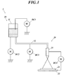
- the electrostatic spray device 1 includes a charging unit 10 and a spraying unit 20.
- the charging unit 10 includes a supply tank 11 that stores the coating liquid and a supply line 12.
- the supply tank 11 is connected to the spray unit 20 via the supply line 12.
- DC power supplies DC1, DC2, and DC3 are connected to the coating liquid in the supply tank 11, the supply tank 11, and the supply line 12, respectively.
- the spray unit 20 includes an injection nozzle 21 and a support 22.
- the injection nozzle 21 and the support 22 are connected to a direct current power source DC4 and are charged with opposite charges.
- a support substrate 23 such as glass or plastic is disposed on the support 22.
- the coating liquid stored in the supply tank 11 is supplied to the spray unit 20 through the supply line 12.
- a direct current voltage is applied to the supply line 12 by a direct current power source DC3, whereby the coating liquid that has passed through the supply line 12 is charged (positive charge).
- the charged coating liquid is sprayed onto the support substrate 23 from the spray nozzle 21.
- a voltage is applied to the injection nozzle 21 and the support 22 by the DC power supply DC4.
- a positive electrode is connected to the injection nozzle 21, and a negative electrode is connected to the support 22. ing.
- the coating liquid sprayed in this state is repelled by the Coulomb force, and splits into droplets each having a positive charge.
- the solvent in the droplets is volatilized and the charge density is increased, so that the droplets are further split and become fine particles.
- the finely divided droplets are attracted to the negative charges of the support 22 and adhere to the support substrate 23. As a result, a desired organic thin film is formed.
- the coating liquid is charged using the DC power supply DC3 connected to the supply line 12. However, even if the coating liquid is charged using the DC power supply DC1 or DC2 connected to the supply tank 11, the coating liquid is charged. Good.
- the electrostatic spray device 1 may be configured to include an ultrasonic spray nozzle or a two-fluid spray nozzle (not shown) instead of the spray unit 20.
- the ultrasonic spray nozzle includes an ultrasonic receiving terminal to which an ultrasonic oscillator capable of oscillating ultrasonic waves of 15 kHz to 130 kHz is connected, a compressed gas injection port, and the like.
- the size of the droplet is determined by the frequency at which the ultrasonic spray nozzle vibrates, the density of the coating liquid, and the surface tension. The higher the frequency, the smaller the size of the droplet and the more fine particles can be formed.
- the two-fluid spray nozzle is connected to the air supply tank and the supply tank 11 via a high-pressure liquid feed pump.
- the coating liquid in the supply tank 11 is supplied to the two-fluid spray nozzle in a high pressure state by a high-pressure liquid feed pump, is atomized by the pressure of the gas supplied from the air supply tank, and is applied onto the substrate.
- the coating solution it is preferable to apply the coating solution while heating the atmosphere in which the droplet flies (between the jet nozzle 21 and the support substrate 23 in FIG. 1) and promoting the evaporation of the droplet.
- the surface has the same polarity as the charged potential of the droplets so as to cover the droplet flying region in order to regulate the droplet flying region. It is preferred to provide a charged conduit. By providing the conduit, a repulsive force due to the Coulomb force between the droplet and the inner surface of the conduit acts, so that the droplet does not scatter around but can adhere to the substrate.
- the charged conduit may be cylindrical or quadrangular, and as the material, for example, a metal coated with a dielectric such as Teflon (registered trademark), an acrylic material, or alumina can be used.
- a metal coated with a dielectric such as Teflon (registered trademark), an acrylic material, or alumina
- a guard ring may be provided to prevent scattering.
- a rectangular or elliptical guard ring is preferably used in order to uniformly form an organic material on the substrate.
- the coating liquid is charged in the charging unit 10, more charged fine particles are formed by using the spray device as described above as compared with the conventional electrostatic spray device. It becomes possible.
- the coating liquid is charged in the supply tank 11 or the supply line 12, and there are, for example, friction charging, induction (indirect) charging, and direct charging.
- Friction electrification is a method in which a solvent is stirred by a stirrer or a solvent is fed by a liquid, and is charged by friction between a stirring blade, a container, a pipe, a filter, and the like.
- a magnetic stirrer (not shown) is installed in the supply tank 11 and the magnetic stirrer is rotated to charge the coating liquid by friction with the coating liquid.
- the supply tank 11 is formed of a non-conductive material.
- the inner wall of the supply line 12 may be coated with a fluororesin such as Teflon (registered trademark) and charged by friction with the fluororesin.
- the supply line 12 made of metal is charged using the DC power source DC3.
- the fluororesin When the supply line 12 is positively charged, the fluororesin is negatively charged, and the coating liquid is positively charged by friction with the fluororesin.
- the voltage applied to the supply line 12 does not need to be a direct current, but charging efficiency deteriorates.
- the faster the stirring speed is, the better, preferably 300 rpm, more preferably 500 rpm or more.
- the longer the stirring time the better, preferably 10 minutes, more preferably 15 minutes or more.
- Induction charging is a method of charging by contact with a charged substance (charging solvent, charged solid, charged gas (gas)).
- induction charging includes a method of charging a coating solution using DC power sources DC2 and DC3. Specifically, when the DC power source DC ⁇ b> 2 is used, a DC voltage is first applied to the supply tank 11, and the coating liquid is indirectly charged through the supply tank 11. At this time, the supply tank 11 is formed of a metal covered with a dielectric. Further, the inner wall of the supply line 12 is coated with a non-conductive material made of resin, ceramic or the like to induce charging. For example, the supply line 12 made of metal is charged using the DC power supply DC3.
- the nonconductive material When the supply line 12 is positively charged, the nonconductive material is polarized with a negative charge on the supply line 12 side and a positive charge on the coating liquid side. Due to the polarized positive charge, a negative charge is induced in the coating solution and is charged.
- the amount of the charged substance is preferably larger than that of the solvent. In the case of using a charged glass rod, the larger the number, the better, preferably 30, and more preferably 40 or more. The longer the time of contact with the charged gas, the better, preferably 7 minutes, more preferably 10 minutes or more.
- Direct charging is a method in which electrons, ions, and radicals themselves are brought into contact with a solvent to be charged.
- the direct charging includes a method of charging a coating solution using a DC power source DC1. Specifically, when the DC power source DC1 is used, a DC voltage is directly applied to the coating solution, and the coating solution is charged. Further, a corona discharge device (not shown) may be connected to the supply tank 11 to charge the coating solution. The higher the concentration of electrons, ions, and radicals, the longer the contact time.
- the coating liquid is charged in advance in the supply tank 11 or the supply line 12 as compared with the conventional electrostatic spray apparatus. Density increases. As a result, the repulsion between the droplets is further increased, the formation of fine particles in the coating liquid is promoted, and as a result, an organic thin film can be formed with a reduced amount of residual solvent.
- the coating liquid is charged in a superimposed manner by the charging unit 10 and the spraying unit 20, the supply amount of the coating liquid can be increased. Furthermore, since the coating liquid is charged in advance in the charging unit 10, the DC power source DC4 can be driven at a low voltage.
- the second embodiment is different from the first embodiment mainly in the following points.
- the electrostatic spray device 2 includes a supercritical solution supply unit 30 and a spray unit 40, and the supercritical solution supply unit 30 and the spray unit 40 are connected via a supply line 12. Has been.
- the supercritical solution supply unit 30 includes a gas cylinder 31, a drying tube 32, a filter 33, a cooler 34, a pressure pump 35, a preheater 36, and a solute dissolution cell 38.
- a gas that becomes a supercritical solution such as carbon dioxide is stored.
- a back pressure valve V ⁇ b> 1 is arranged in parallel with the pressurizing pump 35.
- the solute dissolution cell 38 is provided with an organic EL element material (a constituent material of the organic compound layer), and is appropriately changed depending on the type of the organic compound layer to be formed.
- the preheater 36 and the solute dissolution cell 38 are connected via a check valve 37, and the preheater 36, the check valve 37, and the solute dissolution cell 38 are disposed in a constant temperature bath 39.
- the spray unit 40 includes a filter 41, a spray nozzle 42, and a hot plate 44.
- the injection nozzle 42 and the hot plate 44 are disposed in a clean booth 45.
- a support substrate 43 is disposed on the hot plate 44 and heated to a predetermined temperature.
- the spray nozzle 42 and the hot plate 44 are connected to a direct current power source DC4 and have opposite charges.
- gaseous carbon dioxide is supplied from the gas cylinder 41.
- the supplied carbon dioxide sequentially passes through the drying tube 42, the filter 43, and the cooler 44, and then is pressurized (compressed) by the pressurizing pump 45, and passes through the preheater 46 to become a supercritical solution.
- the supercritical solution flows into the solute dissolution cell 48, dissolves the organic EL element material previously disposed in the solute dissolution cell 48, and becomes a supercritical solute solution phase (solution).
- the supercritical solute solution phase (coating solution) is supplied to the spray unit 40 through the supply line 12.
- a DC voltage is applied to the supply line 12 by a DC power source DC3, whereby the supercritical solute dissolved phase that has passed through the supply line 12 is charged.
- the charged supercritical solute solution phase is sprayed under atmospheric pressure through an injection nozzle 42 heated to an expansion temperature in order to prevent condensation, and is divided into gaseous carbon dioxide and solute molecule clusters.
- the sprayed clusters of solute molecules adhere to the support substrate 43, and as a result, an organic thin film is formed.
- the stop valves V2 to V5 are opened and closed at a predetermined timing, and the solute dissolution pressure and the solute dissolution temperature (pre-expansion temperature) are monitored by the pressure gauge PI and the thermometer TI, respectively.
- the light-emitting layer was formed using the electrostatic spray device 1 including the charging unit 10 and the spray unit 20. Specifically, a light emitting layer coating solution prepared by dissolving 0.1 g of HA, 0.011 g of DA, 0.0002 g of DB, 0.0002 g of DC, and 100 g of butyl acetate in an N 2 atmosphere and having a thickness of 2 mm. The sample was transferred to a glass supply tank having a volume of 500 ml and stirred at 100 rpm for 5 minutes using a magnetic stirrer. At this time, the supply tank is formed of a non-conductive material.
- This light emitting layer coating solution was sprayed on the substrate surface and dried at a substrate surface temperature of 120 ° C. for 10 minutes to provide a light emitting layer. Application was performed under the same conditions on a separately prepared substrate, and the film thickness was measured. The film thickness was 40 nm.
- an electron transport layer coating solution prepared by dissolving 0.75 g of ET-A in 100 g of 2,2,3,3-tetrafluoro-1-propanol It was applied under conditions, and further dried by heating at a substrate surface temperature of 120 ° C. for 30 minutes to provide an electron transport layer. Coating was performed under the same conditions on a separately prepared substrate, and the film thickness was measured. The film thickness was 30 nm.
- barium oxide which is the water catching agent 115
- a high-purity barium oxide powder manufactured by Aldrich is attached to the glass cover 110 with a fluorine-based semipermeable membrane (Microtex S-NTF8031Q manufactured by Nitto Denko) with an adhesive. Prepared and used in advance.
- An ultraviolet curable adhesive was used for bonding the glass cover 110 and the organic EL element 101, and both were bonded by irradiating ultraviolet rays to produce a sealing element.
- the sealing element has a cathode 111 and an organic compound layer 112 formed on a glass substrate 113 with a transparent electrode.
- the glass cover 110 is filled with nitrogen gas 114 and a water catching agent 115 is provided.
- Organic EL Element 104 was produced in the same manner as the organic EL element 101 except that a light emitting layer was formed by applying a voltage of 1 kV to the light emitting layer coating solution when forming the light emitting layer.
- Adhesion efficiency represents the ratio between the amount of mist W applied from the nozzle and the amount of mist Wt adhering to the substrate, and was determined by the following equation.
- Adhesion efficiency (%) Wt / W ⁇ 100
- the mist amount Wt adhering to the substrate is calculated using the solid content concentration of the liquid and the average film thickness d (measured at intervals of 10 mm) at 81 locations of the film adhering to the glass substrate of 100 mm ⁇ 100 mm ⁇ 1.1 mm. It calculated using the following formula
- the organic EL elements 101 to 107 of the present invention have a high film formation rate and high adhesion efficiency. It is clear. Further, the light emitting layer film surface of the organic EL element 106 had a uniform film thickness distribution as compared with the organic EL element 102. Further, the surface of the light emitting layer of the organic EL element 107 was less mixed with the hole transport layer as the lower layer and the amount of residual solvent in the film of the light emitting layer was smaller than that of the organic EL element 102. From the above, it can be seen that the use of the electrostatic spray device and the manufacturing method of the present invention is useful for manufacturing an organic EL element in which layer mixing is prevented and high productivity is ensured.
- organic EL element 201 (1.1) Formation of anode As a positive electrode, a substrate (made by NH Techno Glass) on which 100 nm of ITO (indium tin oxide) is formed on a glass substrate of 100 mm ⁇ 100 mm ⁇ 1.1 mm After patterning NA45), the substrate provided with the ITO transparent electrode was ultrasonically cleaned with isopropyl alcohol, dried with dry nitrogen gas, and subjected to UV ozone cleaning for 5 minutes.
- ITO indium tin oxide
- a light-emitting layer was formed using the electrostatic spray device 2 including the supercritical solution supply unit 30 and the spray unit 40. Specifically, the film was formed using a Teflon (registered trademark) -coated supply line from the supply tank to the injection nozzle. In addition, when it apply
- the organic EL elements 201 to 203 were evaluated as follows. In the evaluation, as in Example 1, the organic EL elements 201 to 203 were sealed, and an illumination device as shown in FIGS. 3 and 4 was configured and evaluated. The evaluation results are shown in Table 2.
- Adhesion efficiency was evaluated by the same method as in Example 1.
- the residual solvent ratio represents the residual solvent content (% by mass) in the organic compound layer (light emitting layer) of the organic EL element. The lower the residual solvent ratio, the smaller the influence on the substrate, and the more effective mixing can be suppressed.
- a quantitative method using a head space type gas chromatograph is used.
- a quantification method using a head space type gas chromatograph a detection method such as an internal standard method used in a normal gas chromatograph is used.
- mass spectrometry (MS) is performed together with measurement of the residual solvent amount.
- an organic EL element sample is collected in a 20 ml headspace vial, and the vial is sealed with a septum using a dedicated crimper.
- the sample amount is weighed to 0.01 g (necessary for calculating the area per unit mass).
- the sample is placed in a constant temperature bath at 170 ° C. and heated for 30 minutes.
- a carrier coated with silicon oil SE-30 so as to have a mass ratio of 15% packed in a column having an inner diameter of 3 mm and a length of 3 m is used as a separation column.
- the separation column is attached to a gas chromatograph, and He is used as a carrier to flow at 50 ml / min.
- the temperature of the separation column is set to 40 ° C., the measurement is performed while increasing the temperature to 260 ° C. at a temperature increase rate of 15 ° C./min, and the temperature is maintained for 5 minutes after reaching 260 ° C. Finally, the vial bottle is taken out from the thermostatic chamber, immediately 1 ml of gas generated from the sample is collected with a gas tight syringe, and this is injected into the separation column. The concentration of each component is obtained by preparing a calibration curve in advance with the aromatic hydrocarbon compound used as the internal reference material.
- Headspace conditions Headspace device: HP7694 manufactured by Hewlett-Packard Company "Head Space Sampler” Temperature conditions Transfer line: 200 ° C Loop temperature: 200 ° C Sample amount: 0.8 g / 20 ml vial (2) GC / MS conditions GC: HP5890 manufactured by Hewlett-Packard Company MS: HP5971 manufactured by Hewlett-Packard Company Column: HP-624 30m x 0.25mm Oven temperature: 40 ° C (3 minutes) -15 ° C / minute-260 ° C Measurement mode: SIM
- the organic EL elements 201 and 202 of the present invention have all of the film formation speed, the deposition efficiency, and the residual solvent amount. It is apparent that the device performance is improved. Further, it can be seen that the amount of residual solvent in the organic EL elements 201 and 202 is effectively reduced as compared with the organic EL element 102. From the above, the use of the electrostatic spray device and the production method of the present invention is useful for producing an organic EL device which prevents layer mixing and ensures high productivity, and particularly useful for reducing the residual solvent amount. It can be seen that it is.
- the present invention can be used particularly suitably to provide an organic thin film device in which layer mixing is prevented and high productivity is ensured.
Landscapes
- Electroluminescent Light Sources (AREA)
- Application Of Or Painting With Fluid Materials (AREA)
- Electrostatic Spraying Apparatus (AREA)
Applications Claiming Priority (2)
| Application Number | Priority Date | Filing Date | Title |
|---|---|---|---|
| JP2012002916 | 2012-01-11 | ||
| JP2012-002916 | 2012-01-11 |
Publications (1)
| Publication Number | Publication Date |
|---|---|
| WO2013105535A1 true WO2013105535A1 (fr) | 2013-07-18 |
Family
ID=48781483
Family Applications (1)
| Application Number | Title | Priority Date | Filing Date |
|---|---|---|---|
| PCT/JP2013/050059 Ceased WO2013105535A1 (fr) | 2012-01-11 | 2013-01-08 | Dispositif de pulvérisation électrostatique, et procédé de fabrication de dispositif de film mince organique mettant en œuvre celui-ci |
Country Status (2)
| Country | Link |
|---|---|
| JP (1) | JPWO2013105535A1 (fr) |
| WO (1) | WO2013105535A1 (fr) |
Cited By (4)
| Publication number | Priority date | Publication date | Assignee | Title |
|---|---|---|---|---|
| TWI652968B (zh) | 2017-01-31 | 2019-03-01 | 日商斯庫林集團股份有限公司 | 基板處理裝置及基板處理方法 |
| JP6786026B1 (ja) * | 2020-04-06 | 2020-11-18 | 三菱電機株式会社 | 加湿装置および加湿方法 |
| JP2021045730A (ja) * | 2019-09-20 | 2021-03-25 | 三菱ケミカルエンジニアリング株式会社 | 反応生成物製造装置及び反応生成物製造方法 |
| WO2021237871A1 (fr) * | 2020-05-29 | 2021-12-02 | 太仓市金港植保器械科技有限公司 | Appareil de pulvérisation électrostatique et procédé de pulvérisation électrostatique |
Citations (5)
| Publication number | Priority date | Publication date | Assignee | Title |
|---|---|---|---|---|
| JPH02198654A (ja) * | 1989-01-25 | 1990-08-07 | Chubu Electric Power Co Inc | 液体の帯電霧化装置 |
| JP2004193123A (ja) * | 2002-12-06 | 2004-07-08 | Eastman Kodak Co | 発光ディスプレイ装置及びその製造方法 |
| JP2007305507A (ja) * | 2006-05-15 | 2007-11-22 | Toppan Printing Co Ltd | 有機エレクトロルミネッセンス素子の製造方法 |
| JP2008264679A (ja) * | 2007-04-19 | 2008-11-06 | Origin Electric Co Ltd | 液体塗布装置 |
| JP2011181271A (ja) * | 2010-02-26 | 2011-09-15 | Hitachi High-Technologies Corp | Esd有機el装置及び方法 |
-
2013
- 2013-01-08 WO PCT/JP2013/050059 patent/WO2013105535A1/fr not_active Ceased
- 2013-01-08 JP JP2013553282A patent/JPWO2013105535A1/ja active Pending
Patent Citations (5)
| Publication number | Priority date | Publication date | Assignee | Title |
|---|---|---|---|---|
| JPH02198654A (ja) * | 1989-01-25 | 1990-08-07 | Chubu Electric Power Co Inc | 液体の帯電霧化装置 |
| JP2004193123A (ja) * | 2002-12-06 | 2004-07-08 | Eastman Kodak Co | 発光ディスプレイ装置及びその製造方法 |
| JP2007305507A (ja) * | 2006-05-15 | 2007-11-22 | Toppan Printing Co Ltd | 有機エレクトロルミネッセンス素子の製造方法 |
| JP2008264679A (ja) * | 2007-04-19 | 2008-11-06 | Origin Electric Co Ltd | 液体塗布装置 |
| JP2011181271A (ja) * | 2010-02-26 | 2011-09-15 | Hitachi High-Technologies Corp | Esd有機el装置及び方法 |
Cited By (5)
| Publication number | Priority date | Publication date | Assignee | Title |
|---|---|---|---|---|
| TWI652968B (zh) | 2017-01-31 | 2019-03-01 | 日商斯庫林集團股份有限公司 | 基板處理裝置及基板處理方法 |
| JP2021045730A (ja) * | 2019-09-20 | 2021-03-25 | 三菱ケミカルエンジニアリング株式会社 | 反応生成物製造装置及び反応生成物製造方法 |
| JP6786026B1 (ja) * | 2020-04-06 | 2020-11-18 | 三菱電機株式会社 | 加湿装置および加湿方法 |
| WO2021205506A1 (fr) * | 2020-04-06 | 2021-10-14 | 三菱電機株式会社 | Dispositif d'humidification et procédé d'humidification |
| WO2021237871A1 (fr) * | 2020-05-29 | 2021-12-02 | 太仓市金港植保器械科技有限公司 | Appareil de pulvérisation électrostatique et procédé de pulvérisation électrostatique |
Also Published As
| Publication number | Publication date |
|---|---|
| JPWO2013105535A1 (ja) | 2015-05-11 |
Similar Documents
| Publication | Publication Date | Title |
|---|---|---|
| US6756084B2 (en) | Electrostatic deposition of particles generated from rapid expansion of supercritical fluid solutions | |
| US6780475B2 (en) | Electrostatic deposition of particles generated from rapid expansion of supercritical fluid solutions | |
| US6749902B2 (en) | Methods for producing films using supercritical fluid | |
| US10946407B2 (en) | Apparatus and method for atomization of fluid | |
| KR102206027B1 (ko) | 박막 형성 장치 및 이를 이용한 유기 발광 소자의 제조 방법 | |
| TW202028519A (zh) | 霧產生裝置、霧成膜方法、霧成膜裝置及微粒子成膜裝置 | |
| WO2013105535A1 (fr) | Dispositif de pulvérisation électrostatique, et procédé de fabrication de dispositif de film mince organique mettant en œuvre celui-ci | |
| EP1507600B1 (fr) | Depot electrostatique de particules issues de l'expansion rapide de solutions fluides supercritiques | |
| JP5876292B2 (ja) | 薄層を溶液コーティングするための装置および方法 | |
| CN115003418B (zh) | 雾成膜装置和雾成膜方法 | |
| JP2004160388A (ja) | 薄膜の作成方法と作成装置 | |
| TW200524680A (en) | Method and apparatus for coating an organic thin film on a substrate from a fluid source with continuous feed capability | |
| JP2012135704A (ja) | エレクトロスプレーデポジション装置 | |
| CN103492088A (zh) | 基板涂布方法、基板涂布装置以及使用了该方法的有机电致发光器件的制造方法 | |
| JP2001332398A (ja) | 静電霧化式イオン化装置および方法並びに荷電粒子搬送式イオン化装置および方法 | |
| JP5414046B2 (ja) | 静電塗布方法及び装置 | |
| JP5316415B2 (ja) | 薄膜形成方法及び有機エレクトロニクス素子 | |
| JP5677253B2 (ja) | 成膜方法および成膜装置 | |
| JP2013249999A (ja) | 塗布膜の乾燥装置及び乾燥方法 | |
| JP2001353454A (ja) | 成膜方法、有機el素子の製造方法及び成膜装置 | |
| JP2016043300A (ja) | 静電塗布装置 | |
| JP2013211366A (ja) | 静電塗布方法を用いた薄膜形成方法 | |
| GB2437227A (en) | Deposition of polymeric films | |
| JP5700043B2 (ja) | 有機薄膜層の形成方法、有機エレクトロルミネッセンス素子の製造方法 | |
| KR20110107353A (ko) | 용액 코팅을 위한 전기-주조 노즐 장치 및 방법 |
Legal Events
| Date | Code | Title | Description |
|---|---|---|---|
| 121 | Ep: the epo has been informed by wipo that ep was designated in this application |
Ref document number: 13736368 Country of ref document: EP Kind code of ref document: A1 |
|
| ENP | Entry into the national phase |
Ref document number: 2013553282 Country of ref document: JP Kind code of ref document: A |
|
| NENP | Non-entry into the national phase |
Ref country code: DE |
|
| 122 | Ep: pct application non-entry in european phase |
Ref document number: 13736368 Country of ref document: EP Kind code of ref document: A1 |