WO2013108398A1 - Plateau de mise en place de composants électroniques, dispositif de positionnement et dispositif de traitement à étapes - Google Patents
Plateau de mise en place de composants électroniques, dispositif de positionnement et dispositif de traitement à étapes Download PDFInfo
- Publication number
- WO2013108398A1 WO2013108398A1 PCT/JP2012/051236 JP2012051236W WO2013108398A1 WO 2013108398 A1 WO2013108398 A1 WO 2013108398A1 JP 2012051236 W JP2012051236 W JP 2012051236W WO 2013108398 A1 WO2013108398 A1 WO 2013108398A1
- Authority
- WO
- WIPO (PCT)
- Prior art keywords
- electronic component
- leaf spring
- shaft
- mounting table
- spring
- Prior art date
- Legal status (The legal status is an assumption and is not a legal conclusion. Google has not performed a legal analysis and makes no representation as to the accuracy of the status listed.)
- Ceased
Links
Images


Classifications
-
- H—ELECTRICITY
- H10—SEMICONDUCTOR DEVICES; ELECTRIC SOLID-STATE DEVICES NOT OTHERWISE PROVIDED FOR
- H10P—GENERIC PROCESSES OR APPARATUS FOR THE MANUFACTURE OR TREATMENT OF DEVICES COVERED BY CLASS H10
- H10P72/00—Handling or holding of wafers, substrates or devices during manufacture or treatment thereof
- H10P72/50—Handling or holding of wafers, substrates or devices during manufacture or treatment thereof for positioning, orientation or alignment
-
- H—ELECTRICITY
- H10—SEMICONDUCTOR DEVICES; ELECTRIC SOLID-STATE DEVICES NOT OTHERWISE PROVIDED FOR
- H10P—GENERIC PROCESSES OR APPARATUS FOR THE MANUFACTURE OR TREATMENT OF DEVICES COVERED BY CLASS H10
- H10P72/00—Handling or holding of wafers, substrates or devices during manufacture or treatment thereof
- H10P72/70—Handling or holding of wafers, substrates or devices during manufacture or treatment thereof for supporting or gripping
- H10P72/78—Handling or holding of wafers, substrates or devices during manufacture or treatment thereof for supporting or gripping using vacuum or suction, e.g. Bernoulli chucks
Definitions
- the present invention relates to an electronic component placement stage that is a stage for performing process processing on an electronic component, a positioning device including the electronic component placement stage, and a process processing device.
- Electronic parts are parts used in electrical products and include semiconductor elements.
- semiconductor elements include transistors and integrated circuits
- electronic components include resistors and capacitors.
- This electronic component is generally transported while being held by a holding means on the transport path.
- Various process processing devices that perform process processing are lined up on the conveyance path, and the holding means descends to the stage included in each, and the electronic component is detached from the stage. When the process processing is completed, the electronic component is removed from the stage. Pick up and transport to next process.
- Examples of the process include pre-processes such as dicing, mounting, bonding, and sealing, and post-process processes such as device electrical property measurement, classification, marking, appearance inspection, and packing. Further, the positioning process for each process is included in the process.
- the stage on which the electronic component provided in each process processing apparatus has a mounting table.
- the mounting table can be moved up and down, and an effort has been made to make the clearance zero while finely adjusting the positional relationship between the holding means and the mounting table in consideration of aging degradation or the like (for example, Patent Document 1). reference.).
- the electronic component is pressed against the mounting table to realize a state where the electronic component and the mounting table are securely in contact with each other. That is, the holding means is lowered by a certain amount even after the electronic component has just touched the mounting table.
- the method of pressing the electronic component against the mounting table can surely make the clearance zero, but this method cannot use a mounting table with high rigidity such as resin or metal. This is because the reaction force of pressing against the mounting table reaches the electronic component and may damage the electronic component. Therefore, at present, rubber mounting tables are frequently used. This is because, when the mounting table is made of rubber, the pressure when the electronic component comes into contact with the mounting table is absorbed by the elastic deformation of the mounting table, and the possibility of damage to the electronic component can be reduced.
- the rubber mounting table is crushed and deformed due to the contact pressure when the electronic component is placed, the electronic component has a restoring force to correct the crushed deformation or the crushed deformation. May cause misalignment.
- the positional shift caused by the rubber mounting table is not so large as the positional shift caused by detaching the electronic component in a state where the clearance between the electronic component and the mounting table is not zero.
- An object of the present invention is to provide an electronic component placement stage that does not cause a positional shift when the electronic component is placed, a positioning device including the electronic component placement stage, and a process processing device.
- the electronic component mounting stage according to the present invention is an electronic component mounting stage on which an electronic component is mounted, and the electronic component mounting table and the mounting table described above are attached to the electronic component mounting table. And a pressure absorbing part that can sink so as to absorb the contact pressure.
- the pressure absorbing portion may be a leaf spring having a fixed edge
- the mounting table may be attached to a central region of the front surface
- the flat portion of the leaf spring may be bent by the contact pressure
- a shaft attached to the back surface of the leaf spring and extending below the leaf spring; and a spring supporting the shaft; the spring in a state where the electronic component is not in contact with the mounting table. You may make it urge
- a shaft attached to the back surface of the leaf spring and extending below the leaf spring, and a shaft support portion for preventing the shaft from falling by sandwiching a lower peripheral surface of the shaft. Good.
- a regulating part that regulates the bending of the leaf spring to the thickness of one piece of the electronic component may be further provided.
- the restricting portion is attached to the back surface of the leaf spring and extends below the leaf spring, a contact surface provided on the shaft and extending so as to intersect the shaft axis, and the contact surface. And a regulating surface positioned below at a distance corresponding to the thickness of one piece of the electronic component, and the contact surface and the regulating surface of the shaft that descends in accordance with the sinking of the leaf spring And the bending of the leaf spring may be restricted to the thickness of one piece of the electronic component.
- the plate spring deflection detection unit may be further provided.
- the deflection detecting unit is blocked by surface contact between a spring supporting the flat surface of the leaf spring and a surface of the leaf spring supported by the spring so that the initial tension of the leaf spring approaches zero.
- a pipe communicating with the opening generating a pressure in the pipe, and detecting a pressure change in the pipe to detect the bending of the leaf spring.
- It further comprises a suction part that sucks the electronic component onto the mounting table, and the suction part extends from the opening to the lower side of the plate spring through the plate spring from the opening provided on the upper surface of the mounting table. You may make it have a pipe which transmits a negative pressure to the said opening.
- a plurality of slits may be formed in the leaf spring, and the slits may be arranged concentrically from the center of the leaf spring toward the outside.
- a non-circular hole is formed on the flat surface of the leaf spring, and a non-circular foot having a size and a shape that matches the non-circular hole protrudes from the bottom surface of the mounting table.
- the mounting table may be attached so as not to rotate with respect to the leaf spring.
- the electronic component positioning device may include a moving mechanism for moving the electronic component mounting stage, and may change the position of the electronic component mounted on the mounting table.
- the electronic component process processing apparatus may include the electronic component mounting stage, and may perform a process on the electronic component mounted on the mounting table.
- the present invention it is possible to deliver the electronic component to the process processing apparatus while reliably reducing the clearance between the electronic component and the mounting table to zero. That is, considering the damage to the electronic component, the electronic component is dropped from the holding means even though there is a gap between the electronic component and the mounting table. There is no worry of it occurring. Further, in order to make the clearance zero, there is no fear that the electronic component is pressed against the mounting table and the electronic component is damaged.
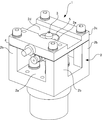
- FIG. 1 is a perspective view showing an appearance of the electronic component placement stage 1.
- the electronic component placement stage 1 is mounted on a process processing apparatus as a process processing stage for the electronic component D.
- the process processing apparatus of this embodiment is a positioning apparatus.
- the positioning device corrects the posture of the electronic component D appropriately.
- the electronic component mounting stage 1 has a mounting table 3 for electronic components D on a gantry 2 as shown in FIG.
- the mounting table 3 of the present embodiment is made of rubber, but various types such as metal and resin can be applied.
- the mounting table 3 has a shape in which a cone is superimposed on a thin cylindrical surface. A flat surface is formed at the tip of the cone, and the electronic component D lands on this flat surface.
- the gantry 2 that accommodates the mounting table 2 is connected to one end of a rotating shaft and is further mounted on an XY moving mechanism (not shown).
- the gantry 2 is moved in the ⁇ direction, the X axis direction, and the Y axis direction by the rotation axis and the XY movement mechanism in a state where the electronic component D is mounted on the mounting table 3, and the electronic component D is positioned by this movement. .
- the gantry 2 has a shape in which a single upper lid 2c is placed on pillars 2b erected at four corners of a thick rectangular base 2a, and the space between the base 2a and the upper lid 2c is hollow. .
- the front surface of the upper lid 2c is a stage surface 2d that performs a process on the electronic component D.
- the gantry 2 is installed such that the holding means 100 (see FIG. 3 and the like) that conveys the electronic component D and the upper lid 2c face each other.
- the upper lid 2c is provided with a through hole 2e for opening the front surface and the back surface.
- the mounting table 3 protrudes from the inside of the gantry 2 through the through hole 2e to the stage surface 2d.
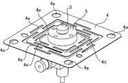
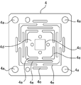
- FIG. 2 is a perspective view in which the gantry 2 is removed and the leaf spring 4 accommodated in the gantry 2 is exposed.
- a plate spring 4 supported inside the gantry 2 is attached to the mounting table 3.
- the mounting table 3 is fixed to the leaf spring 4 via a raising table 5 loosely fitted in a through hole 2e formed in the upper lid 2c.
- the leaf spring 4 is a thin rectangular plate, and the central area 4d is supported in a floating manner by sandwiching the four corners between the support 2b and the upper lid 2c.
- the mounting table 3 is fixed to the floating central region.
- the leaf spring 4 has flexibility and functions as a pressure absorbing portion that absorbs much of the pressure when the electronic component D lands on the mounting table 3 and is further pushed. That is, the central area to which the mounting table 3 is attached sinks downward to absorb the contact pressure when the electronic component D contacts the mounting table 3. Therefore, the leaf spring 4 is thinned, and a large number of slits 4e are formed in order to reduce the rigidity.
- the slits 4e are arranged concentrically from the center of the leaf spring 4 toward the outside, and the sinking center of the leaf spring 4 is shifted from the spreading center of the leaf spring 4, or the center region of the leaf spring 4 is
- the center region of the leaf spring 4 contributes to the accurate sinking without being inclined and sinking, and the positional deviation of the electronic component D is prevented.
- the substantially concentric circle includes a plurality of polygons that have no common point and have the same center in addition to the concentric circle.
- the raising table 5 is configured so that the flat surface of the mounting table 3 continues to protrude from the gantry 2 even if the plate spring 4 sinks due to bending. That is, the combined height of the mounting table 3 and the raising table 5 is adjusted to be slightly higher than the combined height of the thickness of the upper lid 2 c of the gantry 2 and the amount of sinking of the leaf spring 4.
- the through-hole 2e and the raising base 5 have a sufficient clearance so as not to come into contact with each other, and can move relative to each other even if dust enters the gap.
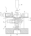
- FIG. 3 is a cross-sectional view of the electronic component placement stage 1 and shows the inside of the gantry 2.
- the shaft 6 is fixed to the back surface of the leaf spring 4 via a block 6 e and extends toward the base 2 a of the gantry 2.
- the back surface is the surface opposite to the mounting table 3.
- the thickness of the leaf spring 4 and the gap existing at the lower end portion of the shaft 6 are exaggerated for easy understanding.
- the shaft 6 includes, for example, a resin cylindrical body and a pin body 6a inserted into an end surface of the cylindrical body on the base 2a side.
- the pin body 6 a has a rod shape having a common axis with the shaft 6. In other words, the pin body 6 a protrudes from the end surface of the shaft 6.
- the outer shape of the shaft 6 has a silhouette in which the diameter on the base 2a side of the gantry 2 is narrowed from the middle to the tip.
- the starting point of this diaphragm is the step 6b.
- the pin body 6a corresponds to a portion that is narrowed once
- the end surface around the pin body 6a corresponds to the step portion 6b.
- the length from the fixed end to the leaf spring 4 to the step portion 6 b is set to be shorter than the length of the column 2 b of the gantry 2 by the thickness of one electronic component D.
- the tip of the pin body 6a on the protruding side is inserted into a recess 7 formed in the base 2a of the gantry 2.
- the recess 7 is formed on an extension line of the shaft 6.
- the clearance between the pin body 6a and the recess 7 is sufficiently narrower than the insertion depth of the pin body 6a.
- the diameter of the recess 7 is set to be sufficiently smaller than the diameter of the step portion 6b of the shaft 6, and the periphery of the recess 7 exists immediately below the region of the step portion 6b.
- the shaft 6 is lifted by a spring 8 disposed below.
- the spring 8 has one end fixed to the shaft 6 and the other end fixed to the base 2 a of the gantry 2.
- This spring 8 is a compression spring stored so as to extend.
- the spring constant of the spring 8 is such that when the leaf spring 4 is not subjected to external force due to the placement of the electronic component D, the shaft 6 is lifted and the initial tension of the leaf spring 4 approaches zero or zero. It is set to keep flat.
- a common pipe 6 c is formed on the shaft 6, the raising base 5, and the mounting base 3.
- the pipe 6 c is formed along the axis of the shaft 6 from the suction hole 3 a provided on the flat surface of the mounting table 3.
- a lead terminal 6 d that leads to the pipe 6 c is attached.
- the lead terminal 6d is connected to a negative pressure generator (not shown) through a conducting tube.
- the pipe 6c is closed by a pin body 6a from the middle.
- the lead terminal 6d is attached above the insertion end of the pin body 6a.
- an opening 2f is formed in the upper lid 2c of the gantry 2 on the surface facing the leaf spring 4.
- the opening 2f is provided closer to the center of the upper lid 2c than the column 2b. In other words, the opening 2f faces a region where the spring body 4 is bent.
- a pipe 2g is formed in the upper lid 2c, and one end of the pipe 2g is an opening 2f.
- a lead terminal 2h leading to the pipe 2g is attached to the side surface of the upper lid 2c, and the lead terminal 2h is connected to a pressure generator (not shown) for generating pressure in the pipe 2g via a conducting tube. The other end of the pipe 2g is stopped inside the upper lid.
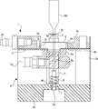
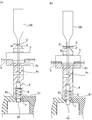
- FIGS. 4 and 5 are cross-sectional views showing the displacement of the pressure absorbing portion.
- FIG. 6 is an enlarged cross-sectional view of the vicinity of the opening 2f formed in the upper lid 2c.
- FIG. 7 is an enlarged cross-sectional view of the lower end portion of the shaft 6.
- the leaf spring 4 is kept flat. This is because the spring 8 lifts the shaft 6 to prevent the plate spring 4 from sinking due to the shaft 6 hanging down. In other words, the movement of the leaf spring 4 attempting to bend due to the weight of the shaft 6 is offset by the pushing back operation by the spring 8 via the shaft 6.
- the leaf spring 4 has flexibility and low rigidity so as to absorb much of the contact pressure when the electronic component D lands on the mounting table 3, and has a small spring constant. Also, the central region 4d is easy to sink. Therefore, the spring 8 and the shaft 6 support the plate spring 4 from below so that the plate spring 4 does not exceed the elastic limit due to its own weight.
- FIG. 4 shows the moment when the clearance between the electronic component D and the mounting table 3 becomes zero.
- the lead terminal 6d and the pipe 6c serve as a suction portion that sucks the electronic component D placed on the placement table 3. That is, the negative pressure generated by the negative pressure generator is transmitted to the suction hole 3a formed on the flat surface of the mounting table 3 through the extraction terminal 6d and the pipe 6c, and the electronic component D is sucked to the mounting table 3.
- the posture of the electronic component D with respect to the mounting table 3 is maintained, and the positional displacement of the electronic component D during the process is prevented.
- the holding unit 100 it is ideal to stop the descent of the holding means 100 immediately after the clearance between the electronic component D and the mounting table 3 becomes zero.
- the holding unit 100 due to the control accuracy of the holding unit 100, it is necessary to prevent a gap from being generated between the electronic component D and the mounting table 3 while the holding unit 100 is stopped. Therefore, the holding unit 100 is further lowered slightly. The slight descent is a degree that ensures the landing of the electronic component D on the mounting table 3.
- FIG. 5 shows a state in which the holding means 100 is further lowered and a contact pressure is generated.
- the leaf spring 4 bends to absorb this contact pressure, and the central region 4d sinks as the holding means 100 is lowered. Therefore, the reaction force of the contact pressure does not reach the electronic component D and the mounting table 3.
- the lead terminal 6d, the pipe 2g, the opening 2f, the shaft 6, and the spring 8 serve as a detection unit that detects the bending of the leaf spring 4. This detection unit is used for detecting the landing of the electronic component D.
- the spring 8 raises the shaft 6 so that the initial tension of the leaf spring 4 approaches zero so that the extension of the leaf spring 4 is kept flat in a state where the electronic component D is not placed. ing. Further, since the leaf spring 4 is sandwiched between the support column 2b of the gantry 2 and the bottom surface of the upper lid 2c, if the leaf spring 4 is kept flat, the upper lid 2c and the leaf spring 4 face each other in the opening area of the opening 2f. It will come into contact.
- the opening 2f is blocked by the leaf spring 4 because the leaf spring 4 is not bent immediately before and immediately after the landing of the electronic component D.
- the leaf spring 4 sinks and there is a gap between the leaf spring 4 and the opening 2f. C is generated. Accordingly, the pressure in the pipe 2g changes before and after the bending of the leaf spring 4, and by capturing this change, the bending of the leaf spring 4 is detected, and thus the landing of the electronic component D is detected.
- a piezoelectric element or an optical sensor that detects the bending of the leaf spring 4, an optical sensor that detects the position of the electronic component D, or the like may be provided as the detection unit.
- the spring 8 does not necessarily have a spring constant that makes the initial tension of the leaf spring 4 approach zero. In this case, it is sufficient for the spring 8 to support the plate spring 4 from below so that the plate spring 4 does not exceed the elastic limit due to its own weight, and a spring constant of that level may be set.
- step portion 6b provided on the shaft 6 and the peripheral edge of the recess 7 formed in the base 2a are a subsidence restricting portion for restricting the bending of the leaf spring 4 to the thickness of one electronic component D. Become. This is because the length of the shaft 6 from the fixed end to the plate spring 4 to the step portion 6b is a length obtained by subtracting the thickness of one piece of the electronic component D from the length of the support 2b.
- the step portion 6b and the periphery of the recess 7 are only the thickness D1 of one electronic component D. Separate.
- the holding means 100 descends and the leaf spring 4 sinks due to the landing of the electronic component D
- the stepped portion 6b is caught on the periphery of the recess 7 as shown in FIG. Therefore, the leaf spring 4 can sink only for the thickness of one electronic component D, and further sinking is restricted.
- the holding unit 100 when the holding unit 100 holds two electronic components D in an overlapping manner, the holding unit 100 cannot reach the specified lowering amount by the sinking restricting portion, and the torque exceeding the specified level. Will receive. Therefore, the subsidence restricting portion can detect the overlapping of the electronic components D in combination with the mechanism for detecting the torque of the holding means 100.
- the lower end peripheral surface of the shaft 6, that is, the peripheral surface of the pin body 6a in the present embodiment, and the recess 7 formed in the base 2a serve as a support portion that prevents the shaft 6 from falling. Since the pin body 6a is inserted into the recess 7 and the clearance between the pin body 6a and the recess 7 is narrow, the pin body 6a hits the inner peripheral wall of the recess 7 even if the shaft 6 tries to fall down so as to swing on the pin body 6a side. Because. For this reason, it is possible to prevent the fall of the shaft 6 from causing the leaf spring 4 to be wrinkled and the shape of the leaf spring 4 from being destroyed.
- the electronic component mounting stage 1 on which the electronic component D is mounted and the mounting table 3 of the electronic component D are provided with the pressure absorbing portion.
- the pressure absorbing part can sink so as to absorb the contact pressure of the electronic component D against the mounting table 3.
- the pressure absorbing portion is a leaf spring 4 with a fixed edge
- the mounting table 3 is attached to the center region 4d of the front surface
- the flat portion of the leaf spring 4 is bent by the contact pressure. Yes.
- the mounting table 3 is made of rubber, the contact pressure is absorbed by the leaf spring 4 side. Therefore, the possibility of the mounting table 3 being crushed by the contact pressure is low, and the electronic component D is misaligned due to the distortion of the rubber mounting table 3 or the restoring force for correcting the distortion. Can be avoided. Furthermore, since the deformation of the rubber mounting table 3 or the friction can be suppressed in addition to this, the life of the rubber mounting table 3 can be extended. In addition, since there is less concern about damage to the electronic component D, the mounting table 3 can be replaced with one having high rigidity such as resin or metal.
- a shaft 6 extending downward is attached to the back surface of the leaf spring 4, and includes a spring 8 that supports the shaft 6.
- the spring 8 is in a state where the electronic component D is not in contact with the mounting table 3. The sag of the leaf spring 4 was urged so as to push back.
- the shaft 6 is attached to the back surface of the leaf spring 4 and extends below the leaf spring 4. And this shaft 6 is pinched
- the pin body 6a is inserted into the other end surface of the shaft 6, and the pin body 6a is inserted into the recess 7 formed in the base 2a.
- the recess 7 has a sufficiently narrow clearance with the pin body 6a as a shaft support portion.
- the restricting portion can be configured by the shaft 6, a stepped portion 6 b provided on the shaft 6, and a peripheral edge of the concave portion 7 provided on the base 2 a.
- the step portion 6 b is a contact surface provided on the shaft 6 and extending so as to intersect the axis of the shaft 6.
- the peripheral edge of the recess 7 is a regulating surface located below the contact surface by a distance corresponding to the thickness of one electronic component D.
- the erroneous delivery can be detected by the occurrence of abnormal torque of the holding means 100.
- the measures for preventing the shaft 6 from falling are not taken or when the measures for preventing the shaft 6 from falling are taken by other methods, it is not necessary to reduce the diameter of the shaft 6 on the base 2a side.
- the front end surface on the 2a side can be the contact surface.
- the restriction portion may be configured by a notch provided on the peripheral surface of the shaft 6 and a rod-like member that has entered into the notch.
- the notch is enlarged in the axial direction of the shaft 6 by the thickness of one electronic component D rather than the diameter of the rod-shaped member.
- the rod-like member is fixed at a fixed position so as to contact the floor surface of the notch.
- the ceiling surface of the notch serves as the abutment surface
- the upper surface of the bar-like member serves as the regulation surface.
- the deflection detection unit is a spring 8, an opening 2f provided in the upper lid 2c, and a pipe 2g drilled in the upper lid 2c.
- the spring 8 supports the flat surface of the leaf spring 4 so that the initial tension of the leaf spring 4 approaches zero.
- the opening 2 f is closed by surface contact with the surface of the leaf spring 4 supported by the spring 8.
- the pipe 2g communicates with the opening 2f.
- the amount by which the electronic device D is pushed by the holding means 100 can be adjusted according to the deflection detection unit, and the adjustment work is facilitated.
- a pressure higher than the pressure of the environment where the electronic component D is installed or a negative pressure may be generated. That is, any method may be used as long as air leakage from the opening 2f and air suction can be detected.
- FIG. 8 shows a leaf spring 4 when the electronic component mounting stage 1 is mounted on a positioning device.
- process processing may be performed while maintaining the holding of the electronic component D by the holding unit 100.
- the electronic component mounting stage 1 is mounted on the positioning device, it is necessary to prevent the mounting table 3 from sliding with respect to the leaf spring 4 due to the ⁇ rotation.
- a square hole 4 c is formed in the plane of the leaf spring 4, and the size and shape of the square hole 4 c are formed on the bottom surface of the raising base 5 in the mounting table 3. It is only necessary to mount the mounting table 3 to the leaf spring 4 in a non-rotatable manner by projecting the combined rectangular feet and inserting the feet into the square holes 4c.
- the square hole 4c and the rectangular foot are merely examples, and any hole and foot having a shape that restricts rotation may be used. That is, if it is a non-circular hole and a leg
- the non-circular shape means a shape in which a plurality of types of distances from the center to the end are clearly present, and includes an ellipse or a polygon such as a hexagon whose minor axis and major axis are clearly different.
- the leaf spring 4 is taken as an example of the pressure absorbing portion.
- a ball spline may be provided as the pressure absorbing portion
- a shaft and a linear bush may be provided as the pressure absorbing portion.
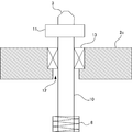
- FIG. 9 shows an example in which a ball spline is provided as a pressure absorber.
- the mounting table 3 is connected to the spline shaft 10 via a joint 11.
- the spline shaft 10 extends below the mounting table 3 toward the base 2 a of the gantry 2.
- the spline shaft 10 has a groove formed along the shaft on the surface.
- a through hole 12 through which the spline shaft 10 passes is formed in the upper lid 2c, and a sleeve main body 13 is attached to the inside of the through hole 12.
- a ball (not shown) is rotatably mounted inside the sleeve body 13, and the ball is fitted in the groove of the spline shaft 13.
- the spline shaft 13 is supported by a spring 8 stored so as to extend.
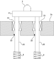
- FIG. 10 shows an example in which a shaft and a linear bush are provided as a pressure absorbing portion.
- the mounting table 3 is connected to two shafts 20 via joints.
- the shaft 20 has a cylindrical shape with a smooth surface.
- two through holes 22 through which the two shafts 20 pass are formed in the upper lid, and linear bushes 23 are attached to the insides of the through holes 22, respectively.
- a ball (not shown) is rotatably mounted inside the linear bush 23, and this ball contacts the surface of the shaft 20.
- the two shafts 20 are respectively supported by springs 8 that are stored so as to extend.
- the leaf spring 4 when the leaf spring 4 is employed as the pressure absorbing portion, the following merits occur. That is, it is easy to achieve downsizing of the electronic component placement stage 1. For example, when the leaf spring 4 is employed, the size of the electronic component placement stage 1 can be easily accommodated in a range of about L30 ⁇ W30 ⁇ H20 (mm).
- This suction part is composed of an suction hole 3a which is an opening provided on the upper surface of the mounting table 3, and a pipe 6c which extends downward from the suction hole 3a through the leaf spring 4 and transmits negative pressure to the opening.
- the pressure absorbing portion is the leaf spring 4
- the pressure absorbing portion is the leaf spring 4
- the cost increases accordingly.
- the shaft 6 attached to the leaf spring 4 since the shaft 6 attached to the leaf spring 4 only supports the leaf spring 4, there is no difficulty in pipe processing.
- Processes for electronic parts D include pre-process and post-process, each assembly process such as dicing, mounting, bonding, sealing, etc., device electrical property measurement, classification, marking, visual inspection, packaging, etc.
- the process processing apparatus of this embodiment is a positioning apparatus.
Landscapes
- Wire Bonding (AREA)
- Die Bonding (AREA)
- Container, Conveyance, Adherence, Positioning, Of Wafer (AREA)
- Supply And Installment Of Electrical Components (AREA)
Abstract
L'invention porte sur un plateau de mise en place de composants électroniques dans lequel un espace libre entre un composant électronique et une base de mise en place est maintenu de manière fiable à zéro, sans risque de détérioration du composant électronique et sans risque de déplacement de la position lorsque le composant électronique est mis en place sur ce plateau. Le plateau de mise en place de composants électroniques (1) sur lequel le composant électronique (D) est mis en place et la base de mise en place (3) pour le composant électronique (D) sont conçus de façon à comprendre une section d'absorption de pression. La section d'absorption de pression est conçue de façon à pouvoir s'abaisser de telle sorte que la pression de contact exercée sur la base de mise en place (3) pour le composant électronique (D) est absorbée. Par exemple, cette section d'absorption de pression est un ressort plat (4) ayant un bord fixe, la base de mise en place (3) est attachée à la région centrale (4d) de la surface avant de ce ressort plat, et la section de surface plate du ressort plat (4) est conçue de façon à fléchir sous la pression de contact.
Priority Applications (2)
| Application Number | Priority Date | Filing Date | Title |
|---|---|---|---|
| JP2013548646A JP5561750B2 (ja) | 2012-01-20 | 2012-01-20 | 電子部品載置ステージ、位置決め装置、及び工程処理装置 |
| PCT/JP2012/051236 WO2013108398A1 (fr) | 2012-01-20 | 2012-01-20 | Plateau de mise en place de composants électroniques, dispositif de positionnement et dispositif de traitement à étapes |
Applications Claiming Priority (1)
| Application Number | Priority Date | Filing Date | Title |
|---|---|---|---|
| PCT/JP2012/051236 WO2013108398A1 (fr) | 2012-01-20 | 2012-01-20 | Plateau de mise en place de composants électroniques, dispositif de positionnement et dispositif de traitement à étapes |
Publications (1)
| Publication Number | Publication Date |
|---|---|
| WO2013108398A1 true WO2013108398A1 (fr) | 2013-07-25 |
Family
ID=48798844
Family Applications (1)
| Application Number | Title | Priority Date | Filing Date |
|---|---|---|---|
| PCT/JP2012/051236 Ceased WO2013108398A1 (fr) | 2012-01-20 | 2012-01-20 | Plateau de mise en place de composants électroniques, dispositif de positionnement et dispositif de traitement à étapes |
Country Status (2)
| Country | Link |
|---|---|
| JP (1) | JP5561750B2 (fr) |
| WO (1) | WO2013108398A1 (fr) |
Cited By (5)
| Publication number | Priority date | Publication date | Assignee | Title |
|---|---|---|---|---|
| CN107378859A (zh) * | 2017-07-13 | 2017-11-24 | 杭州盾牌链条有限公司 | 一种弯板销片装配装置 |
| DE102017008869B3 (de) | 2017-09-21 | 2018-10-25 | Mühlbauer Gmbh & Co. Kg | Bauteilzentrierung |
| DE102019125127A1 (de) * | 2019-09-18 | 2021-03-18 | Mühlbauer Gmbh & Co. Kg | Bauteilhandhabung, Bauteilinspektion |
| WO2021052745A1 (fr) | 2019-09-18 | 2021-03-25 | Muehlbauer GmbH & Co. KG | Dispositif de manipulation de pièces et dispositif d'inspection de pièces |
| DE102021111953A1 (de) | 2021-05-07 | 2022-11-10 | Mühlbauer Gmbh & Co. Kg | Optische Bauteilinspektion |
Families Citing this family (1)
| Publication number | Priority date | Publication date | Assignee | Title |
|---|---|---|---|---|
| CN109454422A (zh) * | 2016-12-26 | 2019-03-12 | 东莞市蓉工自动化科技有限公司 | 一种高精度插入的端子折弯插入机 |
Citations (5)
| Publication number | Priority date | Publication date | Assignee | Title |
|---|---|---|---|---|
| JPS61209829A (ja) * | 1985-03-14 | 1986-09-18 | Fujitsu Ltd | 回転作業用装置 |
| JPS61226285A (ja) * | 1985-03-20 | 1986-10-08 | 富士通株式会社 | 支持装置 |
| JPH03221310A (ja) * | 1990-01-22 | 1991-09-30 | Hitachi Electron Eng Co Ltd | 電子部品のリード線切断装置 |
| JP2000094243A (ja) * | 1998-09-28 | 2000-04-04 | Nissan Motor Co Ltd | エンジン組立体の振れ止め装置 |
| JP2003324633A (ja) * | 2002-04-26 | 2003-11-14 | Olympus Optical Co Ltd | 撮像ユニット組立装置 |
-
2012
- 2012-01-20 JP JP2013548646A patent/JP5561750B2/ja not_active Expired - Fee Related
- 2012-01-20 WO PCT/JP2012/051236 patent/WO2013108398A1/fr not_active Ceased
Patent Citations (5)
| Publication number | Priority date | Publication date | Assignee | Title |
|---|---|---|---|---|
| JPS61209829A (ja) * | 1985-03-14 | 1986-09-18 | Fujitsu Ltd | 回転作業用装置 |
| JPS61226285A (ja) * | 1985-03-20 | 1986-10-08 | 富士通株式会社 | 支持装置 |
| JPH03221310A (ja) * | 1990-01-22 | 1991-09-30 | Hitachi Electron Eng Co Ltd | 電子部品のリード線切断装置 |
| JP2000094243A (ja) * | 1998-09-28 | 2000-04-04 | Nissan Motor Co Ltd | エンジン組立体の振れ止め装置 |
| JP2003324633A (ja) * | 2002-04-26 | 2003-11-14 | Olympus Optical Co Ltd | 撮像ユニット組立装置 |
Cited By (11)
| Publication number | Priority date | Publication date | Assignee | Title |
|---|---|---|---|---|
| CN107378859A (zh) * | 2017-07-13 | 2017-11-24 | 杭州盾牌链条有限公司 | 一种弯板销片装配装置 |
| DE102017008869B3 (de) | 2017-09-21 | 2018-10-25 | Mühlbauer Gmbh & Co. Kg | Bauteilzentrierung |
| WO2019057469A1 (fr) | 2017-09-21 | 2019-03-28 | Muehlbauer GmbH & Co. KG | Dispositif d'orientation et de contrôle optique d'un composant à semi-conducteur |
| US11152243B2 (en) | 2017-09-21 | 2021-10-19 | Muehlbauer GmbH & Co. KG | Device for aligning and optically inspecting a semiconductor component |
| DE102019125127A1 (de) * | 2019-09-18 | 2021-03-18 | Mühlbauer Gmbh & Co. Kg | Bauteilhandhabung, Bauteilinspektion |
| WO2021052745A1 (fr) | 2019-09-18 | 2021-03-25 | Muehlbauer GmbH & Co. KG | Dispositif de manipulation de pièces et dispositif d'inspection de pièces |
| WO2021052756A1 (fr) | 2019-09-18 | 2021-03-25 | Muehlbauer GmbH & Co. KG | Manipulation de pièce comportant une inspection de pièce |
| US11856705B2 (en) | 2019-09-18 | 2023-12-26 | Muehlbauer GmbH & Co. KG | Apparatus for handling components |
| DE102021111953A1 (de) | 2021-05-07 | 2022-11-10 | Mühlbauer Gmbh & Co. Kg | Optische Bauteilinspektion |
| WO2022233521A1 (fr) | 2021-05-07 | 2022-11-10 | Muehlbauer GmbH & Co. KG | Inspection optique d'un composant |
| US12392729B2 (en) | 2021-05-07 | 2025-08-19 | Mb Automation Gmbh & Co. Kg | Optical inspection of a component |
Also Published As
| Publication number | Publication date |
|---|---|
| JPWO2013108398A1 (ja) | 2015-05-11 |
| JP5561750B2 (ja) | 2014-07-30 |
Similar Documents
| Publication | Publication Date | Title |
|---|---|---|
| JP5561750B2 (ja) | 電子部品載置ステージ、位置決め装置、及び工程処理装置 | |
| JP4884537B2 (ja) | 部品実装機、部品装着ヘッド、および部品装着方法 | |
| JP2022172214A (ja) | 接合方法及び接合装置 | |
| US10692833B2 (en) | Apparatus for correcting a parallelism between a bonding head and a stage, and a chip bonder including the same | |
| KR102668030B1 (ko) | 링 프레임의 유지 기구 | |
| JP4943297B2 (ja) | 加圧搭載ヘッドの制御方法及び装置 | |
| JP5427507B2 (ja) | 吸着ノズルの昇降装置及びその荷重制御方法 | |
| JP5718601B2 (ja) | ダイボンダ及び半導体製造方法 | |
| JP5043793B2 (ja) | 自動装着装置 | |
| JP6148180B2 (ja) | バックアップピンおよび基板処理装置 | |
| KR101520677B1 (ko) | 이상 접촉 검출 방법, 전자 부품 유지 장치, 및 전자 부품 반송 장치 | |
| CN104185384B (zh) | 安装部件的安装方法及安装装置 | |
| KR102138991B1 (ko) | 코킹 지그, 및 그것을 사용하는 제조 방법 | |
| JP6440731B2 (ja) | 電子的構成要素実装システム | |
| US20190215997A1 (en) | Optical component mounting device and method for manufacturing sensor device | |
| WO2015122449A1 (fr) | Dispositif de montage de composant, et dispositif de détection | |
| KR102040944B1 (ko) | 표면 실장기의 부품 유지 헤드, 이 부품 유지 헤드에서의 센서 위치 결정 방법, 센서 위치 결정 지그 | |
| JP6115617B2 (ja) | 実装装置 | |
| JP2008135577A (ja) | プリント基板保持装置 | |
| JP2014160181A (ja) | 光学系組立装置 | |
| WO2007116527A1 (fr) | Dispositif de positionnement de porte foup et systeme d'ouverture foup | |
| JP2007027408A (ja) | 電子部品の吸着ノズル機構 | |
| JP2010274359A (ja) | 倣い機構 | |
| CN105472961B (zh) | 表面贴装机的部件吸持头 | |
| KR101975144B1 (ko) | 다이 본더용 칩 본딩 장치 |
Legal Events
| Date | Code | Title | Description |
|---|---|---|---|
| 121 | Ep: the epo has been informed by wipo that ep was designated in this application |
Ref document number: 12865576 Country of ref document: EP Kind code of ref document: A1 |
|
| ENP | Entry into the national phase |
Ref document number: 2013548646 Country of ref document: JP Kind code of ref document: A |
|
| NENP | Non-entry into the national phase |
Ref country code: DE |
|
| 122 | Ep: pct application non-entry in european phase |
Ref document number: 12865576 Country of ref document: EP Kind code of ref document: A1 |