WO2013108417A1 - Dispositif de broyage et rouleau métallique de fabrication de grenaille métallique - Google Patents
Dispositif de broyage et rouleau métallique de fabrication de grenaille métallique Download PDFInfo
- Publication number
- WO2013108417A1 WO2013108417A1 PCT/JP2012/058081 JP2012058081W WO2013108417A1 WO 2013108417 A1 WO2013108417 A1 WO 2013108417A1 JP 2012058081 W JP2012058081 W JP 2012058081W WO 2013108417 A1 WO2013108417 A1 WO 2013108417A1
- Authority
- WO
- WIPO (PCT)
- Prior art keywords
- grit
- metal
- roll
- raw material
- crusher
- Prior art date
- Legal status (The legal status is an assumption and is not a legal conclusion. Google has not performed a legal analysis and makes no representation as to the accuracy of the status listed.)
- Ceased
Links
Images



Classifications
-
- B—PERFORMING OPERATIONS; TRANSPORTING
- B02—CRUSHING, PULVERISING, OR DISINTEGRATING; PREPARATORY TREATMENT OF GRAIN FOR MILLING
- B02C—CRUSHING, PULVERISING, OR DISINTEGRATING IN GENERAL; MILLING GRAIN
- B02C4/00—Crushing or disintegrating by roller mills
- B02C4/28—Details
- B02C4/32—Adjusting, applying pressure to, or controlling the distance between, milling members
-
- B—PERFORMING OPERATIONS; TRANSPORTING
- B02—CRUSHING, PULVERISING, OR DISINTEGRATING; PREPARATORY TREATMENT OF GRAIN FOR MILLING
- B02C—CRUSHING, PULVERISING, OR DISINTEGRATING IN GENERAL; MILLING GRAIN
- B02C4/00—Crushing or disintegrating by roller mills
- B02C4/02—Crushing or disintegrating by roller mills with two or more rollers
-
- B—PERFORMING OPERATIONS; TRANSPORTING
- B02—CRUSHING, PULVERISING, OR DISINTEGRATING; PREPARATORY TREATMENT OF GRAIN FOR MILLING
- B02C—CRUSHING, PULVERISING, OR DISINTEGRATING IN GENERAL; MILLING GRAIN
- B02C4/00—Crushing or disintegrating by roller mills
- B02C4/28—Details
- B02C4/42—Driving mechanisms; Roller speed control
-
- B—PERFORMING OPERATIONS; TRANSPORTING
- B24—GRINDING; POLISHING
- B24C—ABRASIVE OR RELATED BLASTING WITH PARTICULATE MATERIAL
- B24C11/00—Selection of abrasive materials or additives for abrasive blasts
-
- F—MECHANICAL ENGINEERING; LIGHTING; HEATING; WEAPONS; BLASTING
- F16—ENGINEERING ELEMENTS AND UNITS; GENERAL MEASURES FOR PRODUCING AND MAINTAINING EFFECTIVE FUNCTIONING OF MACHINES OR INSTALLATIONS; THERMAL INSULATION IN GENERAL
- F16C—SHAFTS; FLEXIBLE SHAFTS; ELEMENTS OR CRANKSHAFT MECHANISMS; ROTARY BODIES OTHER THAN GEARING ELEMENTS; BEARINGS
- F16C13/00—Rolls, drums, discs, or the like; Bearings or mountings therefor
-
- F—MECHANICAL ENGINEERING; LIGHTING; HEATING; WEAPONS; BLASTING
- F16—ENGINEERING ELEMENTS AND UNITS; GENERAL MEASURES FOR PRODUCING AND MAINTAINING EFFECTIVE FUNCTIONING OF MACHINES OR INSTALLATIONS; THERMAL INSULATION IN GENERAL
- F16C—SHAFTS; FLEXIBLE SHAFTS; ELEMENTS OR CRANKSHAFT MECHANISMS; ROTARY BODIES OTHER THAN GEARING ELEMENTS; BEARINGS
- F16C35/00—Rigid support of bearing units; Housings, e.g. caps, covers
Definitions
- the present invention relates to a crusher for producing grit, and to a metal roll, and in particular to a crusher for producing a grit used for blasting and cutting of stone material, and to a metal roll incorporated in such a crusher. .
- Grit and other metal particles are used as shot materials used in blasting and the like.
- a metal material for producing a grit a metal (a metal) is provided between the opposing outer peripheral surfaces of the metal rolls while rotationally driving a pair of crushing metal rolls disposed so that the outer peripheral surfaces face each other.
- a roll crusher grid manufacturing apparatus
- steel shot is used as a metal material for producing grit
- coarse grain grit sieved from grit produced by crushing may be used as a metal material for producing grit.
- Patent Document 1 discloses a grit manufacturing apparatus for manufacturing a grit by crushing a shot with a crusher 12 (roll crusher).
- Patent Documents 2 to 4 describe the production of a grit using a roll crusher.
- a grit manufacturing apparatus (roll crusher) is known which rotates a pair of crushing metal rolls to crush metal shots (roll crusher), and such a roll crusher is widely used as an apparatus having the highest crush efficiency.
- Patent Document 5 two crushing metal rolls are respectively supported by a fixed bearing seat and a sliding bearing seat, and a spring is disposed between the fixed bearing seat and the sliding bearing seat.
- a shredding device for counter roll type grit manufacturing is disclosed, in which two metal rolls for crushing are connected to a motor via a transmission belt.
- the amount of metal material supplied between a pair of metal rolls may temporarily increase for some reason.
- the metal material (the raw material shot) becomes lumpy, is not crushed between the pair of metal rolls, and is pressed and sandwiched between the outer surfaces of the pair of metal rolls, a so-called "bite" May occur.
- Patent Document 5 has a configuration in which both the fixed bearing seat and the sliding bearing seat 4 elastically deform and absorb an impact when such a “bite” occurs.
- bite occurs, a large force acts on the fixed bearing seat, the sliding bearing seat, the bearing, and the like, and there is a problem that the life of these members is shortened.
- Patent Document 5 requires two drive sources (motors), and thus has a problem that the cost is increased.
- a spring is provided between a fixed bearing seat and a sliding bearing seat for supporting each of the pair of metal rolls so that the two crushing metal rolls do not collide with each other vigorously. Since it arrange
- carbon steels for various machine structures, alloy steels for machine structures, carbon tool steels, alloy tool steels, or these as materials for crushing metal rolls to improve the wear resistance of metal rolls for crushing Attempts have been made to improve the wear resistance by adjusting the hardness and toughness by further performing heat treatment such as quenching and tempering using cast steel having a chemical component similar to that of the above steels.
- the metal roll for crushing is a large part having a weight of about several hundreds of kg and a thickness of 60 mm or more, it is likely to cause a quench crack by quenching and obtain a uniform hardness distribution. Because of the difficulty, there is a problem that the wear becomes uneven.
- the present invention has been made to solve the above-mentioned problems, and it is possible to operate with a single drive source, and to achieve stable crushing of metallic materials while maintaining high durability, and crushing for producing grit. It aims at providing an apparatus.
- Another object of the present invention is to provide a metal roll for crushing which is used in a crusher for producing a grit, which has an appropriate hardness and toughness and which is excellent in wear resistance.
- a crushing apparatus for producing a grit which crushes a metal material between a pair of rotatably arranged metal rolls to produce a grit
- One of the metal rolls is a drive roll driven to rotate by a drive source connected by a drive belt
- the other of the metal rolls is a driven roll.
- the driven roll is disposed between the drive roll and the drive source in a plane parallel to the orbital plane of the drive belt.
- a crusher for producing grit is provided.
- a metal roll that is driven to rotate is referred to as a drive roll
- the other is referred to as a driven roll
- the driven roll is also rotated by the frictional force with the drive roll, so it is not necessary to have two rotational drive means.
- shear stress acts on the raw material for grit production, the crushing efficiency is improved, and the yield rate is improved.
- the driven roll is disposed between the drive roll and the drive source in a plane parallel to the orbital plane of the drive belt, it is possible to make a grit between two metal rolls.
- the tension of the belt is increased, so that it does not slip and stable fracture can be realized.
- both the drive roller and the driven roller have a structure in which there is no radial edge projecting outward, stress concentrates on the radial edge portion projecting outward at both ends and fracture is likely to occur. It is possible to solve the problem of increasing the cost for producing a metal roll for use.
- the rotating shaft of at least one of the metal rolls is supported by a bearing box, It is provided that the bearing box is configured to be slidable in a direction perpendicular to the rotation axis by pressure adjusting means connected to the bearing box.
- the sliding direction of the bearing box is horizontal.
- the pressure adjusting means comprises an elastic body box and an elastic body fixture.
- any one elastic body selected from a spring, air, water and oil is enclosed inside a deformable shell container,
- the elastic box is disposed between the bearing box and the bracket, and is supported and fixed by an elastic fixture attached to the bracket.
- the device can be miniaturized.
- the rotating shaft of at least the other of the metal rolls is supported by a bearing box,
- the bearing box of the other metal roll is connected with position adjusting means for adjusting the horizontal position orthogonal to the rotation axis of the metal roll.
- the position adjusting means is any one of a bolt, an air cylinder, a hydraulic cylinder, and an electric cylinder, It is installed between the bearing box and the bracket.
- the pair of metal rolls are installed in a housing fixed to a frame, A raw material supply mechanism for supplying a raw material for grit production to the metal roll is provided at an upper portion of the housing, and the raw material supply mechanism receives a raw material chute for supplying the raw material between the pair of metal rolls, A raw material dispersion stage for feeding the raw material to the raw material chute while dispersing the raw material in the axial direction of the metal roll, and a raw material dispersion means for dispersing the raw material on the raw material dispersion stage in the axial direction of the metal roll.
- the raw material dispersing means is a vibration generating device driven by electric power or compressed air.
- At least the outer peripheral surface of the pair of metal rolls is made of high manganese cast steel,
- the chemical composition of the high manganese cast steel is% by mass, C: 0.8 to 1.5, Mn: 11 to 33, Cr: 1 to 4, Si: 0.8 or less, the balance being Fe and an unavoidable impurity.
- a high manganese cast steel provides a wear-resistant fracturing metal roll with adequate hardness and toughness.
- the above-mentioned high manganese cast steel has a base structure of retained austenite excellent in toughness, and only the surface part to which an impact is applied during use is work-hardened to transform into a martensitic structure and thus it is excellent in wear resistance and It has toughness and is suitable as a material of a metal roll.
- At least the outer peripheral surface of the pair of metal rolls is made of high manganese cast steel,
- the chemical composition of the high manganese cast steel is mass%, C: 0.9 to 1.3, Mn: 11 to 14, Cr: 1.5 to 2.5, Si: 0.8 or less, the balance is Fe and unavoidable It is an impurity.
- Such high manganese cast steel is more preferable because of low current material cost and high ease of machining.
- a metal roll used in a crusher for producing grit which crushes a metal material between a pair of rotatably arranged metal rolls to produce grit, Preparing a molten metal at 1660 to 1720 ° C. by blending and melting raw materials of high manganese cast steel; Casting the molten metal into a mold; The mold is separated after the casting is cooled, and the casting is taken out. Cleaning and removing the mold material adhering to the casting; A step of removing the pot and the pouring water other than the cast product part, Feeding the cast product portion into a heat treatment furnace at 200 ° C. or less, raising the temperature to 1040 to 1060 ° C.
- a metal roll is provided, characterized in that it is manufactured by a process of machining a cast product part to a defined size.
- a crushing apparatus for producing a grit capable of operating with a single drive source and capable of stably crushing a metal material while maintaining high durability. Furthermore, a metal roll for crushing used in a crusher for producing grit, which has excellent hardness and toughness and is excellent in abrasion resistance is provided.
- FIG. 1 is a schematic front view of a crusher 10 for producing grit according to a preferred embodiment of the present invention
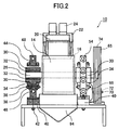
- FIG. 2 is a schematic right side view in which a part of the crusher 10 for producing grit is broken.
- FIG. 3 is a plan view in which a part of the grit manufacturing shredding apparatus 10 is removed with the housing removed.
- a pair of cylindrical metal rolls 16 and 18 are rotatably arranged in parallel (support) in the housing 14 at the top of the frame 12 so that the outer peripheral surfaces are in contact with each other.
- the raw material for grit production is supplied between the outer peripheral surfaces of the pair of metal rolls 16 and 18 and crushed between the pair of metal rolls to form a grit to be discharged below the metal rolls 16 and 18. It is possessed.
- a drive roll 16 and a driven roll 18 constituting a pair of metal rolls 16 and 18 in a housing 14 provided on a frame 12. And are rotatably supported.
- Each of the pair of metal rolls 16, 18 has a substantially cylindrical outer peripheral portion 16a, 18a, and the outer peripheral portion 16a, 18a is made of high manganese cast steel.
- the outer peripheral parts 16a and 18a may have other configurations as long as at least the outermost layer surface is made of high manganese cast steel.
- the chemical component is, by mass%, C: 0.8 to 1.5, Mn: 11 to 33 Cr: 1 to 4, Si: 0.8 or less, and the balance is Fe and unavoidable impurities.
- the crushing apparatus 10 for manufacturing grit is provided with a raw material supply mechanism for supplying metal raw materials (metal particles), which are raw materials for grit manufacturing, supplied from a raw material hopper (not shown) above the frame 12 to the metal rolls 16 and 18 There is.
- the raw material supply mechanism includes a raw material dispersion stand 20 for receiving a metal raw material from an external device such as a raw material hopper, a raw material chute 22 for receiving a metal raw material from the raw material dispersion stand 20 and supplying between a pair of metal rolls 16 and 18; And distribution means 24.
- the raw material dispersing device 24 has a function of dispersing the metal raw material on the raw material dispersing stand 20 in the axial direction of the metal rolls 16 and 18, and in this embodiment, it is a vibration generating device driven by electric power or compressed air.
- a rotary blade driven by an external power, a rotary brush, or the like may be used as the raw material dispersing device 24 .
- a plurality of convex portions may be provided on the surface on which the raw material for grit production of the raw material dispersion stand 20 flows, and it may be used as a raw material dispersion means replacing the raw material dispersion device.
- the convex portion may be used in combination with a vibration generator or the like.
- metal particles supplied from the external apparatus such as the raw material hopper to the portion shown by the arrow in FIG. 1 of the raw material dispersion stand 20 move on the raw material dispersion stand 20 in the direction of the raw material chute 22
- the raw material chute 22 is supplied to the raw material chute 22 while being uniformly spread in the axial direction of the metal rolls 16 and 18 (direction orthogonal to the paper surface of FIG. 1) by the vibration from the device 24.
- the metal particles supplied to the raw material chute 22 are supplied between the metal rolls 16 and 18 substantially uniformly in the axial direction of the metal rolls 16 and 18 and broken.
- the raw material for grit production is uniformly spread and supplied in the width direction of the axial direction of the metal rolls 16 and 18, uneven wear of the outer peripheral surfaces 16a and 18a of the metal rolls 16 and 18 is reduced, and durability is achieved. Improves the quality.
- the wear of the metal roll progresses uniformly, the problem of the grit manufacturing material falling from the gap of the uneven wear portion without being crushed is greatly reduced, and the yield rate is improved.
- a drive shaft 26 and a driven shaft 28 are fixed to radial centers of the drive roller 16 and the driven roller 18, respectively.
- the drive shaft 26 and the driven shaft 28 project at both ends from both side surfaces of the drive roll 16 and the driven roll 18 and are rotatably supported by bearings 32 housed in the bearing boxes 30 and 31.
- the bearing box 30 supporting the drive shaft 26 of the drive roll 16 is fitted and fixed to the drive-side position adjustment slide 34, as shown in the broken portion of FIG.
- the drive side position adjustment slide 34 is bolted to the drive side slide block 36.
- the slide block 36 is slidably supported by the drive side slide plate 38.
- the drive shaft 26 of the drive roll 16 is configured to be slidable in a direction (direction perpendicular to the paper surface in FIG. 2) with respect to the driven shaft 28 of the driven roll 18.
- a gap (not shown) extending in the vertical direction is provided between the drive-side position adjustment slide 34 and the drive-side slide block 36, and a bolt connecting the drive-side position adjustment slide 34 and the drive-side slide block 36
- the axial position of the drive roll 16 can be finely adjusted by adjusting.
- the driven roller 18 is also supported by the driven side position adjustment slide 34 ', the driven side slide block 36' and the like in the same manner as the drive roller 16 side.
- a mounting pedestal 40 for mounting the metal rolls 16 and 18 on the frame 12 is bolted. Furthermore, the lower base 42 is bolted onto the mounting pedestal 40, and the upper base 44 is bolted to the lower base 42 via the distance block 46.
- the upper base 44 and the lower base 42 are formed with holes for passing the tie bars 48, and the tie bars 48 pass through the holes.
- Brackets 54 and 56 are attached to both ends of the tie bar 48 via spacers 50 and 52, and nuts 58 are fastened from the outside of the brackets 54 and 56.
- the drive-side slide plate 38 is exchangeably mounted on the upper surface of the lower base 42 on the drive roll 16 side, and the driven-side slide plate 60 is exchangeably mounted on the driven roll 18 side.
- the drive roll 16 and the driven roll 18 are tapered inwardly in the axial direction so that the inner diameter at both axial ends is maximized.
- a substantially cylindrical outer peripheral portion 16a, 18a forming an internal space is provided.
- roll fasteners 62 tapered in a shape complementary to the internal space are inserted from both ends in the axial direction, and the roll fasteners 62 on both sides are connected by roll connectors 64 such as bolts. ing.
- the drive roll 16 and the driven roll 18 are connected to the drive shaft 26 and the driven shaft 28 by fitting the roll fixing tool 62 to the drive shaft 26 and the driven shaft 28.
- a rotational drive mechanism for rotationally driving the drive roll 16 will be described. As shown in FIGS. 1 and 3, in the grit manufacturing crushing apparatus 10 of the present embodiment, a drive shaft pulley 65 is fixed to one end of the drive shaft 26 of the drive roll 16.
- a motor 66 serving as a drive source of the drive roll 16 is fixed on a mounting pedestal 68 fixed on the frame 1.
- a motor shaft pulley 72 is fixed to the output shaft 70 of the motor 66.
- the drive belt 74 is wound around the drive shaft pulley 65 and the motor shaft pulley 72 so that the rotation of the output shaft 70 of the motor 66 is transmitted to the drive shaft pulley 65.
- a so-called transmission belt is used as the driving belt 74, in which a rubber core material is covered with a jacket, but it is also possible to use other types of driving belts.
- the motor 66 is disposed at the opposite position across the driven roll 18 from the drive roll 16. That is, the driven roll 18 is disposed between the drive roll 16 and the motor 66 in a plane parallel to the orbital plane of the drive belt 74.
- the driven roller 18 is configured to be rotated by the frictional force with the driving roller 16, so the device can be operated by one drive source (motor). As a result, it has become possible to miniaturize the device and reduce the manufacturing cost. Furthermore, since the shear stress acts on the raw material for grit production due to the difference in the rotational speed of the drive roll 16 and the driven roll 18, the crushing efficiency is improved and the non-defective rate is improved.
- the driven roller 18 rotates due to frictional contact with the driving roller 16, it is necessary to adjust the pressing force between the rollers.
- the bearings 32 and the bearing boxes 30 and 31 are provided. Since an excessive load acts, a structure for reducing this load is required.
- the drive roll 16 and the driven roll 18 are rotatably supported by the bearing boxes 30, 31 and are orthogonal to the rotation axis along the slide plates 38, 60.
- the load can be reduced by slidably supporting in the direction of movement.
- the pressure adjustment means acting in the horizontal direction orthogonal to the drive shaft 26 is connected to the bearing box 30 supporting the drive roll 16, and the bearing box 31 supporting the driven roll 16 is orthogonal to the roll axis
- Position adjustment means 76 is connected to adjust the horizontal position.
- the pressure adjusting means comprises an elastic body box 78 and an elastic body fixing tool 80.
- the elastic body box 78 has a structure in which any one elastic body selected from a spring, air, water and oil is enclosed inside a deformable shell.
- the elastic box 78 is installed between the bearing box 30 supporting the drive roll 16 and the drive side bracket 54, and is supported and fixed by an elastic body fixture 80 attached to the drive side bracket 54.
- the elastic box 78 can have a simple structure in which the elastic body is enclosed, the device can be miniaturized.
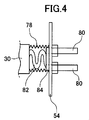
- the structure of the pressure adjusting means using a spring as an elastic body sealed in the elastic body box 78 is shown in FIG.
- a spring 82 and a plate-like elastic connecting member 84 are installed inside the elastic box 78.
- the elastic box 78 has a bellows-like expandable structure covering the spring 82 and the elastic connector 84, and serves to protect the elastic body from dust and raw materials for producing grit, and is made of resin, metal, cloth or the like. The manufactured bellows are used.
- the proximal end side (right side in FIGS. 1 and 4) of the spring 82 and the elastic box 78 is connected to one surface of the elastic body connector 84 connected to the drive side bracket 54. Further, the tip end side (left side in FIGS. 1 and 4) of the elastic body fixing tool 80 is connected and fixed to the other surface of the elastic body connecting tool 84 through the hole portion provided in the drive side bracket 54 There is.
- the pressure adjustment means is disposed between the bearing box 30 supporting the drive roll 16 and the drive side bracket 54, and the bearing box 30 supporting the drive roll 16 supports the driven roll 18 Adjust the pressure applied to 31.
- FIG. 1 A specific structure of the pressure adjusting means in the case of using water or oil as an elastic body instead of the spring 82 is shown in FIG.
- a fluid spring 86 filled with water or oil in a deformable bellows structure container is installed in the elastic body box 78 '.
- the proximal end (right side in FIGS. 1 and 5) portion of the fluid spring 86 is connected to the elastic body connector 84.
- Such an elastic body box 78 ' is disposed between the bearing box 30 supporting the drive roll 16 and the drive side bracket 54, as in the configuration of FIG.
- the fluid spring 86 can optionally control the pressure by fluid communication with the fluid storage container 88, the pressure valve 90, the air pump 92, etc., as shown in FIG.
- the position adjusting means 76 is any one selected from a bolt, an air cylinder, a hydraulic cylinder, and an electric cylinder, and is installed between the driven side bearing box 31 and the driven side bracket 56.
- the driving roller 16 and the driven roller 18 wear due to the crushing operation, the driving roller 16 is pushed toward the driven roller by the pressing pressure from the pressure adjusting means, and the contact point of the both rollers 16 and 18 becomes the raw material chute. It is displaced from the position directly below 22 to the driven roll side. For this reason, the position adjustment means 76 presses the bearing box 31 of the driven roll 18 toward the drive roll to compensate the positions of the both rolls 16 and 18.
- the position adjustment means 76 can be made into a simple structure by using a bolt and various cylinders.
- the elastic box 78 has a configuration in which air, water, and oil are sealed, external devices such as a pump for adjusting the pressure, a tank for storing fluid, and a pressure adjusting valve, as needed.
- the elastic box 78 can be connected to control the pressure in the elastic box 78.
- the position adjustment means 76 is on the side where the motor 66 is installed, there is an advantage that the apparatus does not become large even if various cylinders are used as the position adjustment means 76.
- the raw material for grit production crushed between the pair of metal rolls 16 and 18 flows downward from the discharge chute 94 and is temporarily stored in a hopper or the like (not shown).
- Examples 1 to 3 are three types of high manganese cast steels having different chemical components. Comparative Examples 1 and 2 are two types of chromium molybdenum steels having different chemical components.
- the chemical component is a result of cutting a part of the prototype casting and measuring it by emission spectroscopy. Hardness measurement was performed according to JIS Z2245 (ISO 6508) using C scale (HRC) of Rockwell hardness tester.
- the wear resistance was evaluated by actually producing a pair of rolls and calculating the amount of wear after continuous operation for 100 hours using a steel shot of ⁇ 2 mm as a raw material from the amount of weight reduction.
- the amount of wear of Comparative Example 1 is represented as 100, and the smaller the value is, the better the wear resistance is.
- the impact resistance indicates the presence or absence of the occurrence of cracks after continuous operation for 100 hours.
- the hardness of the high manganese cast steels of Examples 1 to 3 is lower than that of the chromium molybdenum steel of Comparative Example 1, but this is the hardness before use, and the hardness of the outermost surface after use
- the hardness was measured with a micro Vickers hardness tester, it showed Hv 400 to 520, and when converted to Rockwell hardness, it had a hardness corresponding to HRC 40.8 to 50.5.
- the work-hardened layer was as thin as about 0.5 mm from the surface, and the inside had the same hardness as before use.
- the outermost surface is work-hardened to be higher than the hardness of the chromium molybdenum steel of Comparative Example 1, so it is presumed that the wear resistance is improved.
- Comparative Example 2 is an example in which the hardness is increased by increasing C and Si, and although the hardness is the highest, cracks are generated in the rolls after use, and the toughness is insufficient. confirmed.
- the high-manganese cast steels of Examples 1 to 3 have a work-hardening outermost surface and exhibit excellent wear resistance, and a high toughness structure composed of retained austenite inside, so there is a low possibility of generating a crack, which is safe. Sex is high.
- Example 1 is a trial production employing the chemical composition of JIS Standard SCMnH11, and the target component is mass%, C: 0.9 to 1.3, Mn: 11 to 14, Cr: 1.5 to 2. 5, Si: 0.8 or less, the balance is Fe and unavoidable impurities.
- a step of casting a molten metal in a mold a step of performing mold disassembly after cooling of the casting, and taking out the casting, a step of cleaning and removing the casting material adhering to the casting, a crucible and a pouring basin other than the cast product portion
- the cast product part manufactured through the process of removing the metal is transferred to a heat treatment furnace at 200 ° C. or less and then heated to 1040 to 1060 ° C. at a heating rate of 60 ° C./hour to 2 to 4 to 1040 to 1060 ° C.
- a uniform retained austenite matrix is formed by the step of carrying out the water toughening treatment which is uniformly heated by the step of holding for a time and then taken out of the heat treatment furnace, immersed in a water bath and quenched. Furthermore, it was confirmed that manufacturing can be performed by the process of grinding and removing the oxide film formed by the heat treatment, and the process of machining the cast product portion into a defined size.
- Crusher 12 for grit manufacture Frame 14: Housing 16: Drive roll 18: Drive roll 20: Raw material dispersion stand 22: Raw material chute 24: Metal material dispersion means 26: Drive shaft 28: Followed shaft 30: Bearing box 32: Bearing 66: Motor 74: Drive belt
Landscapes
- Engineering & Computer Science (AREA)
- Food Science & Technology (AREA)
- Mechanical Engineering (AREA)
- General Engineering & Computer Science (AREA)
- Crushing And Grinding (AREA)
Abstract
La présente invention concerne un dispositif de broyage de fabrication de grenaille métallique que l'on peut mettre en œuvre à l'aide d'une seule source d'entraînement et qui broie de la matière métallique de manière stable tout en conservant une haute durabilité. La présente invention consiste en un dispositif de broyage de fabrication de grenaille métallique, dans lequel la matière métallique est broyée entre deux rouleaux métalliques (16, 18) agencés en parallèle pour pouvoir tourner, et avec lequel la grenaille métallique est fabriquée. L'un des rouleaux métalliques est le rouleau menant (16), qui est entraîné en rotation par une source d'entraînement (66) en prise par une courroie d'entraînement (74), et l'autre rouleau métallique est le rouleau mené (18). Le rouleau mené (18) est agencé entre le rouleau menant (16) et la source d'entraînement (66) dans un plan parallèle au plan orbital de la courroie d'entraînement (74).
Priority Applications (3)
| Application Number | Priority Date | Filing Date | Title |
|---|---|---|---|
| CN201280000395.4A CN103379960B (zh) | 2012-01-16 | 2012-03-28 | 碎金属制造用的粉碎装置 |
| JP2012521890A JP6021044B2 (ja) | 2012-01-16 | 2012-03-28 | グリット製造用破砕装置、および金属ロールの製造方法 |
| IN3542CHN2014 IN2014CN03542A (fr) | 2012-01-16 | 2012-03-28 |
Applications Claiming Priority (2)
| Application Number | Priority Date | Filing Date | Title |
|---|---|---|---|
| JP2012-006375 | 2012-01-16 | ||
| JP2012006375 | 2012-01-16 |
Publications (1)
| Publication Number | Publication Date |
|---|---|
| WO2013108417A1 true WO2013108417A1 (fr) | 2013-07-25 |
Family
ID=48798861
Family Applications (1)
| Application Number | Title | Priority Date | Filing Date |
|---|---|---|---|
| PCT/JP2012/058081 Ceased WO2013108417A1 (fr) | 2012-01-16 | 2012-03-28 | Dispositif de broyage et rouleau métallique de fabrication de grenaille métallique |
Country Status (4)
| Country | Link |
|---|---|
| JP (1) | JP6021044B2 (fr) |
| CN (1) | CN103379960B (fr) |
| IN (1) | IN2014CN03542A (fr) |
| WO (1) | WO2013108417A1 (fr) |
Cited By (7)
| Publication number | Priority date | Publication date | Assignee | Title |
|---|---|---|---|---|
| CN103586107A (zh) * | 2013-11-28 | 2014-02-19 | 重庆齿轮箱有限责任公司 | 一种制砂机 |
| CN105290433A (zh) * | 2015-12-05 | 2016-02-03 | 重庆腾通工业设计有限公司 | 一种车削铁屑的细化装置 |
| KR20160001911U (ko) * | 2014-11-26 | 2016-06-03 | 박수천 | 유리 파쇄기 |
| CN106540775A (zh) * | 2016-10-21 | 2017-03-29 | 山东省农业机械科学研究院 | 岩棉废棉粉碎装置 |
| CN113718080A (zh) * | 2021-08-25 | 2021-11-30 | 镇江东丰特殊合金有限公司 | 一种高性能球墨铸铁球化剂及其制作设备 |
| CN116592636A (zh) * | 2023-04-25 | 2023-08-15 | 中际同创电子科技(江苏)有限公司 | 一种镁铝电脑壳体铸件轻量化铸造用熔炼设备 |
| CN116749067A (zh) * | 2023-08-02 | 2023-09-15 | 安徽依格尔精密铸造有限公司 | 一种不锈钢精密铸件表面去氧化皮设备 |
Families Citing this family (5)
| Publication number | Priority date | Publication date | Assignee | Title |
|---|---|---|---|---|
| JP3299258B2 (ja) | 1989-12-30 | 2002-07-08 | ライオン株式会社 | シリコーンの乳化方法及びそれによって得られるシリコーン乳化液 |
| CN105435895A (zh) * | 2013-11-13 | 2016-03-30 | 蒋春花 | 金属破碎机的工作方法 |
| CN106269062A (zh) * | 2016-08-26 | 2017-01-04 | 陈学红 | 一种电机驱动式色料研磨辊驱动装置 |
| CN106475386A (zh) * | 2016-12-09 | 2017-03-08 | 无锡银联齿轮传动机械有限公司 | 行走小车驱动系统的可调式传动轴支撑安装结构 |
| CN108722541B (zh) * | 2018-06-26 | 2023-12-05 | 常州好迪机械有限公司 | 回炉料破碎抛丸系统 |
Citations (8)
| Publication number | Priority date | Publication date | Assignee | Title |
|---|---|---|---|---|
| JPS48588Y1 (fr) * | 1969-09-04 | 1973-01-09 | ||
| JPS6067148U (ja) * | 1983-10-13 | 1985-05-13 | 住友金属鉱山株式会社 | 粉粒体の整流装置 |
| JPH10180633A (ja) * | 1996-12-19 | 1998-07-07 | Nobuchika Mimura | 表面形状を整形した破砕片及び同破砕片の製造方法 |
| JPH1190251A (ja) * | 1997-09-22 | 1999-04-06 | Kurimoto Ltd | 高Mn鋳鋼よりなる耐摩耗部材 |
| JP2001104810A (ja) * | 1999-10-13 | 2001-04-17 | Matsushita Electric Ind Co Ltd | ブラウン管構成素材分別のための前処理方法と前処理装置 |
| JP2003038968A (ja) * | 2001-07-31 | 2003-02-12 | Komatsu Ltd | インパクトクラッシャの隙間調整装置 |
| CN1846864A (zh) * | 2006-04-21 | 2006-10-18 | 永安市恒盛合金钢铸造有限责任公司 | 一种钢砂生产方法 |
| JP2011020039A (ja) * | 2009-07-15 | 2011-02-03 | Masami Kawana | 廃コンクリート破砕装置 |
Family Cites Families (9)
| Publication number | Priority date | Publication date | Assignee | Title |
|---|---|---|---|---|
| CN1117529A (zh) * | 1994-08-26 | 1996-02-28 | 孔繁印 | 贝氏体合金抗磨铸球、衬板和生产工艺及设备 |
| CN2326331Y (zh) * | 1998-03-17 | 1999-06-30 | 河北赞皇机械厂 | 一种面粉机喂料装置 |
| US6349890B1 (en) * | 2000-03-20 | 2002-02-26 | Ibt, Inc. | Flaker mill having high efficiency drive |
| KR100871307B1 (ko) * | 2001-07-27 | 2008-12-01 | 가부시키가이샤 고마쓰 세이사쿠쇼 | 파쇄장치, 그의 간격조정장치 및 이들을 탑재한 이동식파쇄기 |
| CN2776542Y (zh) * | 2005-03-04 | 2006-05-03 | 张立建 | 一种单辊驱动的双辊式破碎机 |
| JP2007154295A (ja) * | 2005-12-08 | 2007-06-21 | Kobe Steel Ltd | 耐摩耗性鋳鋼およびその製造方法 |
| CN100540711C (zh) * | 2006-11-21 | 2009-09-16 | 鞍钢集团矿业公司 | 超高性能耐磨高锰钢及其生产方法 |
| CN201337924Y (zh) * | 2008-12-17 | 2009-11-04 | 肖学良 | 垃圾破碎机 |
| CN102247906B (zh) * | 2011-06-01 | 2013-07-10 | 祁阳宇晖机电实业有限公司 | 一种中压辊压制砂机 |
-
2012
- 2012-03-28 WO PCT/JP2012/058081 patent/WO2013108417A1/fr not_active Ceased
- 2012-03-28 CN CN201280000395.4A patent/CN103379960B/zh active Active
- 2012-03-28 IN IN3542CHN2014 patent/IN2014CN03542A/en unknown
- 2012-03-28 JP JP2012521890A patent/JP6021044B2/ja active Active
Patent Citations (8)
| Publication number | Priority date | Publication date | Assignee | Title |
|---|---|---|---|---|
| JPS48588Y1 (fr) * | 1969-09-04 | 1973-01-09 | ||
| JPS6067148U (ja) * | 1983-10-13 | 1985-05-13 | 住友金属鉱山株式会社 | 粉粒体の整流装置 |
| JPH10180633A (ja) * | 1996-12-19 | 1998-07-07 | Nobuchika Mimura | 表面形状を整形した破砕片及び同破砕片の製造方法 |
| JPH1190251A (ja) * | 1997-09-22 | 1999-04-06 | Kurimoto Ltd | 高Mn鋳鋼よりなる耐摩耗部材 |
| JP2001104810A (ja) * | 1999-10-13 | 2001-04-17 | Matsushita Electric Ind Co Ltd | ブラウン管構成素材分別のための前処理方法と前処理装置 |
| JP2003038968A (ja) * | 2001-07-31 | 2003-02-12 | Komatsu Ltd | インパクトクラッシャの隙間調整装置 |
| CN1846864A (zh) * | 2006-04-21 | 2006-10-18 | 永安市恒盛合金钢铸造有限责任公司 | 一种钢砂生产方法 |
| JP2011020039A (ja) * | 2009-07-15 | 2011-02-03 | Masami Kawana | 廃コンクリート破砕装置 |
Cited By (9)
| Publication number | Priority date | Publication date | Assignee | Title |
|---|---|---|---|---|
| CN103586107A (zh) * | 2013-11-28 | 2014-02-19 | 重庆齿轮箱有限责任公司 | 一种制砂机 |
| CN103586107B (zh) * | 2013-11-28 | 2016-05-04 | 重庆齿轮箱有限责任公司 | 一种制砂机 |
| KR20160001911U (ko) * | 2014-11-26 | 2016-06-03 | 박수천 | 유리 파쇄기 |
| KR200481672Y1 (ko) | 2014-11-26 | 2016-11-09 | 박수천 | 유리 파쇄기 |
| CN105290433A (zh) * | 2015-12-05 | 2016-02-03 | 重庆腾通工业设计有限公司 | 一种车削铁屑的细化装置 |
| CN106540775A (zh) * | 2016-10-21 | 2017-03-29 | 山东省农业机械科学研究院 | 岩棉废棉粉碎装置 |
| CN113718080A (zh) * | 2021-08-25 | 2021-11-30 | 镇江东丰特殊合金有限公司 | 一种高性能球墨铸铁球化剂及其制作设备 |
| CN116592636A (zh) * | 2023-04-25 | 2023-08-15 | 中际同创电子科技(江苏)有限公司 | 一种镁铝电脑壳体铸件轻量化铸造用熔炼设备 |
| CN116749067A (zh) * | 2023-08-02 | 2023-09-15 | 安徽依格尔精密铸造有限公司 | 一种不锈钢精密铸件表面去氧化皮设备 |
Also Published As
| Publication number | Publication date |
|---|---|
| IN2014CN03542A (fr) | 2015-09-25 |
| JPWO2013108417A1 (ja) | 2015-05-11 |
| JP6021044B2 (ja) | 2016-11-02 |
| CN103379960B (zh) | 2016-11-09 |
| CN103379960A (zh) | 2013-10-30 |
Similar Documents
| Publication | Publication Date | Title |
|---|---|---|
| JP6021044B2 (ja) | グリット製造用破砕装置、および金属ロールの製造方法 | |
| US4848683A (en) | Crushing members used in pulverizers | |
| US20120037735A1 (en) | Roller mill for coffee | |
| US20250242353A1 (en) | Tooth for fragmenting apparatus and system | |
| CN110170352A (zh) | 一种破碎机 | |
| CN104416014B (zh) | 卷筒用冲击吸收单元以及芯轴卷材箱 | |
| CN100553826C (zh) | 合金粉体原料及其制造方法 | |
| JP5845979B2 (ja) | コークス炉装入用石炭の製造方法 | |
| KR101090237B1 (ko) | 메탈그릿 제조장치 및 그것의 롤러 제조방법 | |
| CN100348327C (zh) | 物料粉碎机 | |
| CN210252435U (zh) | 一种用于不合格玻璃的破碎装置 | |
| CN206577858U (zh) | 还原矿粉高速粉碎机 | |
| US20130161475A1 (en) | Vibration dampening base assembly for a grinding mill | |
| JP3365481B2 (ja) | 高Mn鋳鋼よりなる大型の耐摩耗部材 | |
| CN105709878A (zh) | 一种高效锤片式粉碎机 | |
| CN223324632U (zh) | 一种调节机构及磨煤机磨辊拆装装置 | |
| JP2008272712A (ja) | 粉砕ロール及び該粉砕ロールを備えた粉砕装置 | |
| CN220371138U (zh) | 一种网格式铁合金破碎装置 | |
| CN110819897A (zh) | 适用于半自磨机大直径耐磨钢球生产的材料和方法 | |
| CN222567836U (zh) | 一种颚式破碎机 | |
| US1091042A (en) | Pulverizing-mill. | |
| JP4315739B2 (ja) | 破砕機用刃体とその製造方法 | |
| CN205550390U (zh) | 定间隙免齿对辊粉碎机 | |
| CN221287996U (zh) | 一种重金属磨粉机 | |
| JP5624306B2 (ja) | 破砕装置 |
Legal Events
| Date | Code | Title | Description |
|---|---|---|---|
| ENP | Entry into the national phase |
Ref document number: 2012521890 Country of ref document: JP Kind code of ref document: A |
|
| 121 | Ep: the epo has been informed by wipo that ep was designated in this application |
Ref document number: 12865698 Country of ref document: EP Kind code of ref document: A1 |
|
| NENP | Non-entry into the national phase |
Ref country code: DE |
|
| 122 | Ep: pct application non-entry in european phase |
Ref document number: 12865698 Country of ref document: EP Kind code of ref document: A1 |