WO2013108432A1 - Ruban adhésif à presser pour couper - Google Patents
Ruban adhésif à presser pour couper Download PDFInfo
- Publication number
- WO2013108432A1 WO2013108432A1 PCT/JP2012/069611 JP2012069611W WO2013108432A1 WO 2013108432 A1 WO2013108432 A1 WO 2013108432A1 JP 2012069611 W JP2012069611 W JP 2012069611W WO 2013108432 A1 WO2013108432 A1 WO 2013108432A1
- Authority
- WO
- WIPO (PCT)
- Prior art keywords
- adhesive tape
- cut
- notch
- longitudinal direction
- length
- Prior art date
- Legal status (The legal status is an assumption and is not a legal conclusion. Google has not performed a legal analysis and makes no representation as to the accuracy of the status listed.)
- Ceased
Links
Images










Classifications
-
- C—CHEMISTRY; METALLURGY
- C09—DYES; PAINTS; POLISHES; NATURAL RESINS; ADHESIVES; COMPOSITIONS NOT OTHERWISE PROVIDED FOR; APPLICATIONS OF MATERIALS NOT OTHERWISE PROVIDED FOR
- C09J—ADHESIVES; NON-MECHANICAL ASPECTS OF ADHESIVE PROCESSES IN GENERAL; ADHESIVE PROCESSES NOT PROVIDED FOR ELSEWHERE; USE OF MATERIALS AS ADHESIVES
- C09J7/00—Adhesives in the form of films or foils
- C09J7/20—Adhesives in the form of films or foils characterised by their carriers
-
- C—CHEMISTRY; METALLURGY
- C09—DYES; PAINTS; POLISHES; NATURAL RESINS; ADHESIVES; COMPOSITIONS NOT OTHERWISE PROVIDED FOR; APPLICATIONS OF MATERIALS NOT OTHERWISE PROVIDED FOR
- C09J—ADHESIVES; NON-MECHANICAL ASPECTS OF ADHESIVE PROCESSES IN GENERAL; ADHESIVE PROCESSES NOT PROVIDED FOR ELSEWHERE; USE OF MATERIALS AS ADHESIVES
- C09J2301/00—Additional features of adhesives in the form of films or foils
- C09J2301/10—Additional features of adhesives in the form of films or foils characterized by the structural features of the adhesive tape or sheet
- C09J2301/18—Additional features of adhesives in the form of films or foils characterized by the structural features of the adhesive tape or sheet characterized by perforations in the adhesive tape
Definitions
- the present invention relates to a strip-like adhesive tape used for attaching packaging, paper, and the like, and a strip-like adhesive tape used for temporary fixation such as fixing of a container and a lid, binding of a bundle of food packs, and the vicinity of the center in the short direction
- a plurality of cuts along the longitudinal direction of the pressure-sensitive adhesive tape, or a perforation or a group of perforations formed continuously at intervals in place of the cuts which relates to a “push-cut pressure-sensitive adhesive tape” having ease of cutting. .
- Patent Document 1 discloses a device relating to an adhesive tape that can be cut to a predetermined length under the name “adhesive tape having a cutting portion”.
- the device disclosed in Patent Document 1 is provided with a perforated cut portion capable of cutting the tape body at regular intervals in the longitudinal direction of the tape body in which an adhesive is applied to at least one surface of the tape substrate.
- the present invention relates to an adhesive tape having a cutting part. In the device having such characteristics, the adhesive tape can be reliably and easily cut without using a cutting metal fitting or the like by providing the cut portion in the form of a perforation.
- Patent Document 2 discloses an invention named “easy tearable adhesive tape”.
- the invention disclosed in Patent Document 2 is characterized in that a fine recess is formed on the entire surface of one side of a non-extensible and dimensionally stable plastic film, and an adhesive layer is provided on at least one side of the film. And In the invention having such a configuration, it has a strength that can withstand the tensile strength applied during the packaging operation and the like, and has an end tear resistance that can be easily cut from the end portion without requiring a cutting tool.
- Patent Document 3 discloses a device named “strong adhesive tape with a cut”.
- the device disclosed in Patent Document 3 is characterized in that cuts are provided at an angle of 20 degrees or less from the side surface of the strong adhesive tape, and the cuts are alternately provided from both side surfaces.
- the adhesive tape can be easily cut from the side surface by providing the cut.
- Patent Document 4 discloses an invention relating to a pressure-sensitive adhesive tape that maintains hand-cut property and has improved tensile strength and the like, and a device for manufacturing the same, under the name “hand-cut adhesive tape and its manufacturing device”.
- the invention disclosed in Patent Document 4 is a pressure-sensitive adhesive tape formed by providing a pressure-sensitive adhesive layer on one surface of a belt-shaped plastic film substrate, and forming continuous holes at regular intervals along the longitudinal direction. It is a shape that does not have a corner, and is provided on the inner side of 1.5 mm or more from the side edge of the tape.
- the hand-cut adhesive tape having such a configuration the hand-cut performance is not impaired, and there is no portion where stress is concentrated in the manufacturing and handling operations in each hole, so that the tensile strength and the tensile elongation are improved.
- Patent Document 5 discloses an invention relating to an easily-cut adhesive tape that is called “adhesive tape” and prevents unintentional cutting of the adhesive tape and can be easily cut with a weak finger force.
- the invention disclosed in Patent Document 5 is characterized in that a scar is provided along the longitudinal direction of the tape on the inner side away from the edge of the adhesive tape having an arbitrary width made of a plastic film.
- the adhesive tape having such a configuration since the scar as a starting point of cutting is given at an inner position away from the end edge of the tape, there is no decrease in the strength of the end edge of the tape.
- the disadvantages of unintentional cutting from the end edge due to excessive tension, fluctuating tension, and oblique tension which have been a problem with the prior art easy-cut adhesive tape having a scar near the end edge, are greatly improved.
- Patent Document 6 discloses a device relating to an adhesive tape that can be easily separated by hand after applying the tape under the name "perforated general-purpose adhesive tape".
- the device disclosed in Patent Document 6 is characterized in that a perforation is made in the length direction of the tape near the center of the width of the general packaging pressure-sensitive adhesive tape.
- a perforation is made in the length direction of the tape near the center of the width of the general packaging pressure-sensitive adhesive tape.
- a plurality of cardboard boxes are arranged, and a plurality of boxes are connected by attaching the pressure-sensitive adhesive tape to the seam. Therefore, these can be transported together and can be easily separated by tapping the perforation of the tape with a hand.
- the adhesive tape can be reliably and easily cut without using a cutting metal fitting or the like by providing a cut portion provided with a perforated slit.
- the film base material of the adhesive tape used for packaging, fixing the container and lid, bundling a bundle of food packs, attaching paper or the like is thin, the tensile strength cannot be secured by this method and the film is cut.
- both hands are required. Therefore, when one hand is blocked during the work, the work must be interrupted and the work must be resumed after cutting the tape, and it may not be easy to cut the adhesive tape.
- the finger touches the adhesive surface the trace of the fingerprint may remain on the adhesive tape and impair the appearance. Furthermore, it may be difficult for the adhesive tape to get entangled with fingers after cutting and to stick the adhesive tape.
- the invention disclosed in Patent Document 2 has an endurance resistance that can withstand the tensile strength applied during packaging operations and the like and can be easily cut from the end without the need for a cutting tool.
- the side end portions of the base film have a large formation density of the concave portions.
- the central region in the width direction is formed with a coarser density than the side end portion against the tensile force. Therefore, the hand cutting property is good mainly at the side edge of the base film, and when the side edge of the base film is first torn, depending on the direction, the center does not cut and only the side edge is separated. there's a possibility that.
- the adhesive tape can be easily cut from the side surface by providing the cut at an angle of 20 degrees or less.
- the adhesive tape is very easily cut by the force applied to the side edge. For this reason, when a film base material is peeled off from the wound body of the adhesive tape, if a force is applied to the side edge portion, it tears and is difficult to peel off from the wound body.
- the adhesive tape is pressed from above and cut as in the present application.
- this cutting method is unspecified by the force of pushing from above to cut perforations. It is a method of cutting by connecting scars to be cut.
- This adhesive tape has many scars in the immediate vicinity of the cut end, so when peeling the adhesive tape's cut end from the roll, force is applied to the scar near the cut end and the adhesive tape cuts vertically and can not be used. High nature.
- this adhesive tape is used for temporary fixation, there is a high possibility that the adhesive tape will be cut along the scar group by an unintended force.
- a perforation is formed at the center in the short direction of the packaging adhesive tape, and the cardboard boxes connected by cutting from the perforation are separated. . Since this adhesive tape is cut using a perforation, it may be easily cut by an external force during transportation. Furthermore, since it is necessary to match the seam and the perforation of the cardboard box, care must be taken when connecting the boxes.
- the main problem to be solved when cutting an adhesive tape without using a cutting tool as described above is that a tensile strength can be secured while being cut by a simple operation. Also, do not touch the adhesive surface when cutting, and only the side edges will not be cut, the adhesive tape will not cut unintentionally when cutting or peeling the adhesive tape from the roll, etc., maintaining the appearance quality of the adhesive tape.
- the adhesive tape used for temporarily fixing the article is difficult to break except when the article is unfixed, and is easily released when necessary.
- the present invention provides an adhesive tape that can be easily cut at any position in the longitudinal direction of the adhesive tape by pressing the surface of the adhesive tape from above with a fingertip or a nail. The purpose is to provide. It is another object of the present invention to provide a pressure-sensitive adhesive tape that can be adjusted by adjusting its tensile strength and ease of cutting.
- the invention described in claim 1 is a pressure-sensitive adhesive tape provided with an adhesive layer on at least one surface of a strip-shaped film substrate, and a plurality of strips along the longitudinal direction of the strip-shaped film substrate.
- the incisions having a length of not less than 0.3 mm and not more than 3 mm are continuously arranged at intervals to form a row, and this row is provided in the center of the strip-shaped film base in the short direction, and further,
- the longitudinal direction of the notches penetrating them is formed with an angle ⁇ (10 degrees ⁇
- belt-shaped film base material points out the support body of an adhesive tape, and the center of a transversal direction is a concept also including substantially the center or the center vicinity.
- an arbitrary portion in the longitudinal direction of the adhesive tape to be pressed and cut is fixed by hand or fixed to an object, and the center in the short direction of the adhesive tape to be pressed and cut. Press near the top of the band-shaped film base with the tip of your finger or the nail. As a result, a pulling force is generated between the fixed part and the pressed part of the pressure-sensitive adhesive tape to be pushed and cut. This pulling force becomes a force that expands the cut itself made in the center in the short direction of the belt-like film substrate.
- the notch becomes difficult to expand as it moves away from the pressed part, The notch closest to the pressed part begins to expand. Furthermore, since the force which pulls an adhesive tape to a longitudinal direction is acting, a notch expands toward the both-sides edge part of the transversal direction of the adhesive tape to push and cut. Therefore, the adhesive tape that is pushed and cut at the time of cutting does not tear in the longitudinal direction. Further, since the cut is formed at the center in the short direction of the pressure-sensitive adhesive tape to be pushed and cut, only the side edge portion is not cut as in Patent Document 4.
- the cut is arranged at the center in the short direction of the adhesive tape. Further, a plurality of cuts are continuously arranged at intervals along the longitudinal direction so as to be cut at any part of the adhesive tape.
- a force that pulls in the longitudinal direction acts on the adhesive tape that is pushed and cut when it is peeled off from the wound body, used, or manufactured.
- the pressure-sensitive adhesive tape to be pushed and cut is required to have a tensile strength that is not cut by this pulling force and to be easily cut by pressing the pressure-sensitive adhesive tape surface.
- the required tensile strength and ease of cutting when the surface of the adhesive tape is pressed differ depending on the actual use situation and purpose of use, but the adhesive tape to be pressed and cut can be adjusted by the angle of cut ⁇ and the length of the cut. This will be described below.
- the present invention cuts the adhesive tape by expanding the cut.
- the cut angle ⁇ is 0 degree, even if the adhesive tape is pulled in the longitudinal direction, the cut is not expanded, so that the tensile strength hardly decreases.
- the absolute value of the angle ⁇ increases from 0 degree, that is, as the longitudinal direction of the cut approaches a state parallel to the short direction of the adhesive tape, the cut is easily expanded and the tensile strength is descend.
- the absolute value of the angle ⁇ is 90 degrees, the tensile strength is the lowest.
- the angle ⁇ is 10 degrees ⁇
- the angle of a notch does not need to be constant in several notches, and may differ for every notch.
- the length of the notch is 0.3 mm or more and 3 mm or less, preferably 2 mm or less.
- the reason for this is that, with a tape such as a general OPP film, it is difficult to extend the cut with a cut of less than 0.3 mm, and it is difficult to deform and cut the tape, but the cut is about 5 mm. As a result, the tensile strength is greatly reduced. Furthermore, if the cut is long, even if one side of the cut is peeled off when it is peeled off from the wound body or the like, the other side remains on the wound body and is easily torn from the cut part. In particular, such a phenomenon occurs as the cut direction is closer to 90 degrees with respect to the peeling direction. Therefore, it is desirable that the thickness is 0.3 mm or more and 3 mm or less, preferably 2 mm or less. Furthermore, 2 mm or less is preferable because cutting is possible when the length of the cut is 0.3 mm or more, and therefore it is desirable that the dimensions be as short as possible to ensure the tensile strength without selecting the tape material. is there.
- the strip-like film base material of the pressure-sensitive adhesive tape to be pushed and cut has some elasticity, the cut becomes difficult to expand as the position where the cut is pushed away from the cut, and the pressure-sensitive adhesive tape to be pushed and cut becomes difficult to cut. For this reason, it is better that the interval between the cuts in the longitudinal direction is narrow.
- the pressure-sensitive adhesive tape is not cut in the longitudinal direction when it is cut.
- the pressure-sensitive adhesive tape is cut by force such as when the pressure-sensitive adhesive tape is peeled off from the roll. May be connected in the longitudinal direction and cut vertically.
- the interval between the cuts in the longitudinal direction of the pressure-sensitive adhesive tape is not less than 1 times the cut length, and is preferably at least 2 mm.
- the adhesive tape is likely to be cut in the longitudinal direction at an interval shorter than the length of the cut and is in a so-called vertical cut state.
- the tape width was cut into 1 mm width and 2 mm width, and as a result of performing a tensile test, it became long and difficult to cut at 2 mm width. Even when the length is short, it is desirable that there is an interval of about 2 mm.
- the interval between the cuts in the longitudinal direction refers to the shortest interval in the longitudinal direction between the ends of the cuts adjacent to each other in the longitudinal direction.
- the notches in claim 1 refer to those in which a part of the film substrate is simply notched in the thickness direction, and means that there is no opening and no area. Therefore, it does not include those formed by deliberately removing a part of the film substrate, but it does not include those formed with a certain area, but a slight area generated when the film substrate shrinks when cutting with laser or the like
- the opening is included in the notch in claim 1.
- the notch which penetrates means what penetrated the film base material, it does not exclude the slightly unpenetrated notch generated when the actual notch is formed.
- the shape of the cut includes not only a straight line but also an indeterminate form formed by a curve or a protrusion.
- the adhesive layer is less likely to leak onto the surface of the film. Therefore, it is difficult to get sticky or dirty. In addition, the appearance quality can be maintained because the cuts do not become noticeable because they are not dirty. Further, if a part of the film base material is removed as a hole, it is not desirable because the removed base material needs to be processed, and a notch is desirable.
- the tensile strength in the longitudinal direction of the pressure-cut adhesive tape and the cutting of the pressure-sensitive adhesive tape to be cut Ease can be adjusted. The tensile strength and ease of cutting are adjusted to suit the purpose and method of use.
- the invention according to claim 2 is the pressure-sensitive adhesive tape according to claim 1, wherein the plurality of slits penetrated in place of the one-row arrangement provided in the center in the short direction.
- a plurality of rows that are continuously arranged at intervals along the longitudinal direction of the belt-like film base material are formed within the range of 2/3 of the length from the center in the short side direction to both side edges.
- the cuts in the plurality of rows form a staggered arrangement with each other, and a plurality of through rows of cuts Among these, in some or all of the plurality of through-cuts in the row, the longitudinal direction of these cuts was formed at an angle ⁇ (10 degrees ⁇
- the position of pressing with the fingertip or nail from above may vary from the vicinity of the center to the periphery.
- the belt-like film base material has some extensibility, the force for expanding the cut becomes weaker as the distance from the place where the force is applied. Therefore, by arranging multiple rows of notches within the range of 2/3 each of the length from the center in the short direction of the strip-shaped film base to both side edges, even if the pressing position varies, any of the notches Sufficient force can be applied to the surface to stably cut.
- what is in the range of about 2/3 is also included in the range of 2/3.
- the cuts are expanded even when the absolute value of the angle ⁇ is small, so that the necessary tensile strength can be ensured and it is easy to cut.
- notches are not arranged near both side edges, only the side edges are not cut when the adhesive tape is peeled from the wound body as in the case of claim 1.
- the row includes a row meandering within the range of 2/3 each of the length from the center in the short direction of the belt-like film substrate to both side edges. .
- the angle may be different depending on the row, and the angle ⁇ is different for each cut. May be.
- the tensile strength does not decrease as the absolute value of the angle ⁇ decreases.
- the mechanism for cutting the adhesive tape when the band-shaped film substrate is pressed with the fingertip from above is the same as in the first aspect, and only one notch is involved, so a perforation is formed in the short direction of the adhesive tape. There is no need.
- pushing and cutting since the direction of tearing is directed to both side edges by the force of pulling in the longitudinal direction of the adhesive tape, it is not cut zigzag in the longitudinal direction. Moreover, it is not necessary to control the direction of tearing by the arrangement of notches (interval between notches) and the direction of the notches (angle ⁇ ).
- the interval between the longitudinal cuts of the adhesive tape in the same row is preferably at least 1 mm of the length of the cut and at least 2 mm or more.
- the shortest distance from the cut end to the nearest cut end to prevent unintentional cuts when peeling the cut end of the adhesive tape from the roll Should be opened 2mm or more.
- the longitudinal notch interval be 2 mm or more regardless of the row. However, this does not apply when there is no problem in use, such as not often peeling the cut end of the adhesive tape from the roll.
- the distance between the rows is preferably 1.5 times or more of the length of the cut, and more preferably at least 3 mm.
- the safety factor between the rows is 1.5 times. There is nothing else. In this way, by providing a notch interval or a row interval, unintentional cutting is unlikely to occur when the cut end of the adhesive tape is peeled off from the wound body or at the time of cutting.
- the pressure-sensitive adhesive tape of the above configuration by adjusting the number of rows of cuts, the interval between rows, the length of the cuts, the angle of the cuts, and the intervals in the longitudinal direction of the cuts, You can adjust the tensile strength and ease of cutting the adhesive tape.
- the tensile strength and ease of cutting are adjusted to suit the purpose and method of use. In addition, it has the same action as the pressure-sensitive adhesive tape of claim 1 for cutting.
- the invention described in claim 3 is a perforated or perforated adhesive tape having an adhesive layer on at least one surface of a belt-like film substrate, the length of which is 0.3 mm or more and 3 mm or less.
- the assembly is continuously arranged at intervals along the longitudinal direction of the belt-like film substrate in the range of 2/3 each of the length from the center in the short direction of the belt-like film substrate to both side edges.
- This row is provided with one or a plurality of rows, and the rows are provided at least 1.5 times the length of the perforation or perforation set and at least 3 mm apart.
- the longitudinal direction of the mesh or perforation set is formed with an angle ⁇ (10 degrees ⁇
- the perforation described above is such that a minute notch is arranged in the same length as the notch on a straight line in the same direction as the longitudinal direction of the notch penetrating instead of the notch penetrating according to claim 1 and claim 2.
- the perforation set refers to a plurality of perforations forming one set in parallel and having a length of 0.3 mm or more and 3 mm or less.
- the fine cuts forming the perforation are connected (continuous) to form one cut substantially equal to the cut through.
- Subsequent cutting methods are the same as those in the first and second aspects. Therefore, by applying a local force from the fingertip or nail to the tape surface, one through notch almost equal to the perforation is completed, and this notch expands to reach the side edges at both ends of the adhesive tape and is cut. Has an effect. Since the cut forming the perforation is very small, it is difficult to expand the cut even if the adhesive tape is pulled in the longitudinal direction. For this reason, the perforation of the same length has a strong tensile strength as compared with a single notch.
- the minute notches between the multiple perforations will be easily connected (continuous), and cut more than in the case of a single row. It has the effect of becoming easier.
- the minute cuts that remain without being cut near the cut end of the adhesive tape also increase, so unintentional cuts may occur when peeling the cut end of the adhesive tape from the roll. Easy to wake up.
- the number of rows of perforations is determined according to the usage method of the adhesive tape, but the number of rows is preferably two.
- the intervals between the minute notches forming the perforations and the intervals between the plurality of parallel perforations are such that they can be easily cut when a local force is applied from above to the pressure-sensitive adhesive tape.
- the invention according to claim 4 is the pressure-sensitive adhesive tape according to any one of claims 1 to 3, wherein the strip-shaped film base material is a part including notches, perforations, or perforated aggregates. It has the part which is not provided with the adhesion layer.
- the strip-shaped film base material is a part including notches, perforations, or perforated aggregates. It has the part which is not provided with the adhesion layer.
- the cut is expanded when a force is applied with a nail or a fingertip, and the adhesive tape is easily torn. Furthermore, since it is easier to cut the adhesive tape if the adhesive layer is not provided in the direction in which the cut is expanded, there may be a portion not provided with the adhesive layer in the peripheral portion including the cut and the side edge. On the contrary, since the complete cutting may not be necessary depending on the use of the pressure-sensitive adhesive tape to be pushed and cut, the peripheral portion including a part of the cuts and the side edges may be provided with an adhesive layer.
- the application of the adhesive layer to the belt-shaped film substrate is easier to produce the adhesive tape, for example, by applying up to about half the width in the short direction along the longitudinal direction of the adhesive tape.
- the adhesive tape having two rows of cuts on the left and right sides from the central portion in the short direction the cuts do not expand and are not cut because one row sticks to what is bound.
- disconnect by providing an adhesion layer you may abbreviate
- the adhesive tape is peeled off from the article as a temporary release of the article, it is not adhered to the article unless there is an adhesive layer around the cut end, and this part is easily grasped and peeled off.
- the length of the adhesive tape required for fixing the article is known in advance, cuts are made for each required length or for a certain length, and adhesive is applied from the notch and the periphery of the cut to one or both sides. This can be achieved by not providing a layer. In addition, it has the same action as the pressure-sensitive adhesive tape of any one of claims 1 to 3.
- the pressure-sensitive adhesive tape according to claim 1 of the present invention when a concentrated force from above is applied to the tape surface near the center of the pressure-cut adhesive tape by a fingertip, a nail or the like, one of the cuts arranged in the center. One stretches toward the side edge and the adhesive tape is cut. For this reason, it has the effect that it is hard to tear an adhesive tape to a longitudinal direction at the time of a cutting
- the operation at the time of cutting is simply performed by pressing the vicinity of the center of the adhesive tape in the short direction with the tip of the finger or the nail, even a child can perform it with one hand.
- the tape since the finger does not touch the adhesive layer of the adhesive tape at the time of cutting, the tape may adhere to the finger after cutting, making it uncomfortable or entangled, and leaving fingerprint marks on the adhesive tape Absent. Further, even when the adhesive tape is not cut, such as when the adhesive tape is peeled off from the wound body, since the cut is near the center in the short direction of the adhesive tape, only the side edge portion is not cut. Furthermore, although the tensile strength required for adhesive tapes and the ease of cutting differ depending on the purpose of use, the length and the angle ⁇ of the notch can be adjusted by considering the material and thickness of the adhesive tape film. Necessary tensile strength and ease of cutting can be secured. For example, as shown in FIG.
- the adhesive tape can be cut. For this reason, the number of notches per unit area can be reduced. In this way, the pressure-sensitive adhesive tape that is pushed and cut can have various configurations, and thus has high versatility. In addition, the pressure-sensitive adhesive tape has a small cut and has almost no opening area, so it is excellent in appearance. In addition, since the adhesive tape can be cut at a specific position by adjusting the interval between the cuts, it can contribute to cost reduction and product uniformity in applications such as always using a fixed length for industrial use. it can.
- the pressure-sensitive adhesive tape can be cut very easily with local force in the vicinity of the cut, but on the other hand, if surface pressure is applied to the pressure-sensitive adhesive tape during transportation or handling, the cut will not occur.
- the adhesive tape is difficult to cut because it does not expand so much. The same applies when a local force is applied in addition to the vicinity of the notch.
- the pressure-sensitive adhesive tape of the present invention is suitable for temporarily fixing the lid of the container or for bundling food packs.
- the pressure-sensitive adhesive tape according to claim 2 of the present invention since force acts on any one of the plurality of rows, even a wide pressure-sensitive adhesive tape having a width of 24 mm in the short direction is stable. Can be cut.
- opening is facilitated.
- the lid, the main body, and the lid are fixed.
- the lid and the main body can be separated by starting to tear from any of the cuts by simply rubbing the periphery of the cut located in the gap between the lid and the main body with a nail. Subsequently, the lid can be easily opened by similarly performing the periphery of the joint between the lids.
- the same advantageous effects as those of the pressure-sensitive adhesive tape to be pressed and cut according to claim 1 are obtained.
- the pressure-sensitive adhesive tape according to claim 3 of the present invention since a force is required to connect the minute cuts forming the perforation, compared with a pressure-sensitive adhesive tape having a single cut through. Although the ease of cutting slightly decreases, the tensile strength of the adhesive tape itself can be improved.
- a set of notches that are continuous in a perforated shape can be formed by penetrating a thin film needle having a wedge-shaped tip or the like through the belt-like film base material, which facilitates processing operations and has a great merit in manufacturing. Furthermore, the effect on the appearance is small.
- the pressure-sensitive adhesive tape to be pressed and cut according to claim 4 of the present invention is used for temporary fixation, it is necessary to release the fixation by cutting the adhesive tape or removing the adhesive tape.
- the cutting of the adhesive tape it is easy to cut because it does not have an adhesive layer in a part including notches, perforations or perforated aggregates.
- the part to be cut may stick to the product and the cut does not expand and it may be difficult to cut.
- the pressure-sensitive adhesive tape to be cut and pressed according to claim 4 since there is no adhesive layer in a part including the cut, the cut can be easily expanded as a trigger for cutting.
- disconnection in a specific intended place is attained by making the part which does not have an adhesive layer partially along a longitudinal direction.
- the peripheral portion of the cut end is not adhered to the article, so that this portion is easily grasped and peeled off.
- the pressure-sensitive adhesive tape that has a portion that does not have an adhesive layer, such as a cut and the perforation can keep the appearance quality high without causing the adhesive material to ooze out from the cut.
- the present invention having the above-described configuration can cut the adhesive tape without touching the adhesive layer while ensuring the necessary tensile strength. And only the side edge part of an adhesive tape is not cut
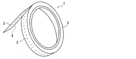
- FIG. 1 is an external perspective view of an adhesive tape that is pressed and cut according to the present invention.
- (A) And (b) is an enlarged view of the notch
- (A) And (b) is a figure which shows the relationship between the tensile strength and angle in an OPP film and a cellophane tape, respectively.
- or (c) is a figure which shows the relationship between the tensile strength and the notch angle in the OPP film whose notch length is 1 mm, the OPP film whose notch length is 5 mm, and the cellophane tape whose notch length is 2 mm, respectively. It is.
- FIG. 2nd modification concerning Example 2.
- FIG. 2nd modification are usage examples of the second modified example according to the second embodiment. These are top views of the adhesive tape which pushes and cuts concerning Example 3.
- FIG. These are the top views of the notch of Example 3.
- FIG. These are the top views of the notch of Example 3.
- FIG. These are the top views of the 1st modification of the notch of Example 3.
- FIG. These are top views of the 2nd modification of the notch of Example 3.
- FIG. These are top views of the adhesive tape which pushes off according to Example 4.
- FIG. These are the usage examples of the adhesive tape which pushes and cuts which concern on Example 4.
- FIG. These are the use condition diagrams of the 1st modification which concerns on Example 4.
- FIG. These are the use condition diagrams of the 2nd modification which concerns on Example 4.
- FIG. These are top views of the 3rd modification concerning Example 4.
- FIG. These are the use condition diagrams of the 4th modification concerning Example 4.
- FIG. These are the top views of the 5th modification based on Example 4.
- FIG. These are the use condition diagrams of the 5th modification concerning Example 4.
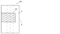
- FIG. These are the top views of the 6th modification based on Example 4.
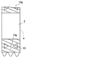
- FIG. These are the top views of the 7th modification based on Example 4.
- FIG. 1 is an external perspective view of an adhesive tape according to the present invention.
- an adhesive tape 1 according to the present invention has a wound body 5 and is provided with an adhesive layer 4 on the back surface of a film substrate 2, and the longitudinal direction in the center in the short direction of the film substrate 2.
- a plurality of slits 3 are continuously provided in a row at regular intervals. Further, the cut 3 penetrates the film base 2.
- the notch 3 may not necessarily be a complete center but may be formed near the center. That is, the center in the present application is a concept including a substantially center.
- the wound body 5 shows the state comprised by the adhesive tape 1 being wound by itself or the circumference
- the film base 2 was formed into a belt shape by biaxially stretched polypropylene film (hereinafter referred to as OPP film) made of polypropylene, a synthetic resin such as acetate, or a film made of cellophane, or a plurality of layers. Things are used.
- FIG. 2A and FIG. 2B are enlarged views of the cut of the adhesive tape according to the present invention, respectively.
- the notch 3a having the length a provided in the adhesive tape 1a is provided with an angle ⁇ .
- the angle ⁇ is an angle formed by the longitudinal direction of the cut 3a and the longitudinal direction of the adhesive tape 1a.
- the angle ⁇ is 0 degrees and parallel to the short direction.
- a certain case is set to 90 degrees or -90 degrees.
- the sign of the angle ⁇ is indicated by plus when the clock is clockwise and minus when it is counterclockwise.
- FIG.2 (b) has shown the case where the notch 3b with which the adhesive tape 1b is equipped is provided continuously over 2 rows along the longitudinal direction of the adhesive tape 1b, and was provided over 2 rows. It is a schematic diagram for demonstrating the space
- b is the distance between the longitudinal cuts 3b in the same row
- c is the distance between the two rows of the cut 3b
- d is the longitudinal distance between the upper and lower ends of the cuts 3b existing in different rows.
- E is the distance in the longitudinal direction between the upper end and the upper end of the notches 3b existing in different rows.
- the positional relationship of the notches 3b is expressed by the shortest distances b, c, d, and e shown in the drawing.
- e 0, that is, when the film substrate 2 is horizontally disposed in the lateral direction, the cuts 3b are in a parallel arrangement, and the others are in a staggered arrangement.
- the upper end of the adhesive tape 1b has shown the cut end when it cuts by pushing.
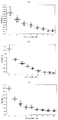
- FIG. 3A and FIG. 3B are graphs showing the relationship between the tensile strength and the cutting angle in the OPP film and the cellophane tape, respectively.
- the tensile strength refers to the difficulty of breaking when the adhesive tape is pulled in the longitudinal direction.
- a commercially available OPP adhesive tape having a width of 18 mm and a cellophane tape having a width of 20 mm were used, and the load (g) at the time of cutting the adhesive tape was taken as the tensile strength.
- the measurement was performed by changing the cut angle ⁇ . A specific measurement method will be described in detail below.
- the cut was formed on an iron ruler using a craft cutter knife so as to have a predetermined length.
- the tape sticks to the ruler so that the cut does not expand.
- One notch was formed at the center in the short direction of the tape.
- One end of this tape is fixed to a round plate with a horizontal plate, and the other end is hung vertically.
- the end part of the adhesive tape hanging vertically was stuck on the peripheral surface of the cylinder.
- the distance to the plate on which the cylinder and the tape were fixed was about 4 cm.
- the spring and auxiliary weight are hung on this cylinder, and the spring is pulled down at a constant speed in the vertical direction.
- the scale of only the spring returns to 0, but the maximum value just before cutting was recorded by sandwiching the recording paper with the scale of only the spring.
- the cut angle ⁇ was changed every 10 degrees from 10 degrees or 20 degrees to 90 degrees, and the maximum value was repeatedly measured 7 to 25 times at the same cut angle.
- a value obtained by adding the weight of the auxiliary weight and the weight of the cylinder to the maximum value was expressed in grams and used as a measurement value of tensile strength.
- FIG. 3 (a) is a diagram showing an average value of measured values of tensile strength for each notch angle with respect to an OPP film having a notch length of 1 mm and an OPP film having a notch length of 5 mm.
- the tensile strength is 1441 (g) when the angle ⁇ is 90 degrees.
- the tensile strength is comparable when the angle ⁇ is 20 degrees.
- FIG.3 (b) is a figure which shows the average value of the measured value of the tensile strength for every angle of a notch regarding the cellophane tape whose notch length is 2 mm. The statistical values of the measured values are shown in Table 1.
- FIGS. 4 (a) to 4 (c) show the tensile strengths of an OPP film having a cut length of 1 mm, an OPP film having a cut length of 5 mm, and a cellophane tape having a cut length of 2 mm, respectively. It is a figure which shows the relationship between a measured value and a notch angle. These figures show the same measurement results as in FIGS. 3 (a) and 3 (b), and show the more detailed measurement results with the statistical values shown in Table 1. .
- the measured values are represented by attaching a box plot and an average rhombus.
- the upper and lower ends of a rectangular box indicate 25% and 75% of the quantile
- the horizontal line in the box indicates the median median.
- a line extending up and down from the box is called a beard.
- the box-and-whisker plot shows the distribution of measured values.
- the upper and lower ends of a rectangular box and the positions of 25% and 75% of quantiles are arranged at equal intervals across the median median.
- the measured value away from the whisker is an outlier. Since the measured values are not largely deviated from the normal distribution from the boxplot, the average value can be used as the representative value.
- the central horizontal line of the average diamond indicates the sample average, and the upper and lower ends of the diamond indicate the 95% confidence interval.
- the width of the diamond represents the number of samples (see Table 1 for specific sample numbers). It can be seen that there is no difference in the average value if the diamonds have the same tensile strength.
- 3A, FIG. 4A, FIG. 4B, and Table 1 in the OPP film, the tensile strength of the adhesive tape increases as the cut length a decreases. Further, from FIG. 3A, FIG. 3B, FIG. 4A, FIG. 4B, FIG. 4C, and Table 1, in both the OPP film and the cellophane tape, the notch angle ⁇ The smaller the becomes, the stronger the tensile strength.
- FIGS. 5 (a) to 5 (c) show the tensile strength and cutting angle of an OPP film having a cut length of 1 mm, an OPP film having a cut length of 5 mm, and a cellophane tape having a cut length of 2 mm, respectively.
- Table 2 shows the relationship between the ease of cutting and the angle of cut when the pressure-sensitive adhesive tape corresponding to claim 1 is pressed from above.
- the measurement was carried out by using a commercially available 18 mm wide OPP adhesive tape and a 20 mm wide cellophane tape, and changing the cut angle every 10 degrees.
- the measurement was carried out by fixing one of the cut adhesive tapes and pressing the top of the adhesive tape near the cut with a nail from above.
- the test was performed several times at the same angle, and the ease of cutting when pressed was evaluated in four stages: “cut well”, “cut”, “not easily cut”, and “not cut”.
- the cut angle ⁇ is 10 degrees, it is considerably harder to cut than 20 degrees.
- the cutting angle ⁇ is 0 degree, the cutting is almost impossible. From these results, it can be seen that when the cutting angle ⁇ is 20 degrees or less, the ease of cutting the adhesive tape decreases as the cutting angle ⁇ decreases.
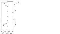
- FIG. 6 is a plan view of the pressure-sensitive adhesive tape according to Example 1
- FIG. Table 3 summarizes the configuration of the adhesive tape 6 according to Example 1.
- the length a of the notch, the distance b in the longitudinal direction of the notch, and the distance c in the short direction of the notch in Table 3 are those shown in FIGS. 2 (a) and 2 (b). Note that the present invention is not limited by this illustration.
- the pressure-sensitive adhesive tape 6 according to Example 1 includes a pressure-sensitive adhesive layer 4 on the back surface of the film base 2 and is provided with a plurality of cuts 7.
- the notch 7 has a length a (see FIG. 2A, the same applies hereinafter) of 0.8 mm, and a uniform interval b of 3 mm along the longitudinal direction of the adhesive tape 6 in the center of the film base 2 in the short direction. (See FIG. 2 (b), the same applies hereinafter).
- the film base 2 is a film having a length of 12 mm in the short direction made of OPP. Further, the cut 7 is provided with an angle ⁇ of 30 degrees.
- the notch 7 is opened substantially perpendicularly to the thickness direction of the adhesive tape 6 and its longitudinal section is linear. The depth is almost equal to the thickness of the film substrate 2 and penetrates the film substrate 2 (not shown).
- the upper end of the adhesive tape 6 has shown the cut end when it cuts by pushing.
- the adhesive tape 6 is cut even if a force is applied at any position in the longitudinal direction. Also has an effect. Moreover, when the length of the notch 7 is changed, it has the effect
- the adhesive tape 6 can be easily cut only by pressing it with a fingertip or a nail. In the prior art, it was necessary to cut with both hands, but the adhesive tape 6 is particularly excellent in that it is very easy to cut. Further, since the adhesive tape 6 is pressed from the film base 2 side, the adhesive tape 4 can be cut without touching the adhesive layer 4. Therefore, it can be used comfortably and the fingerprint is not left on the adhesive layer 4 and the aesthetic appearance is excellent. Further, it is possible to prevent the adhesive tape from adhering to the finger at the time of cutting or after cutting, or from becoming unusable due to tangling.
- the adhesive tape 6 is difficult to tear along the longitudinal direction, when the adhesive tape 6 is peeled off from the wound body 5, the adhesive tape 6 may be cut unintentionally and a part of the adhesive tape 6 remains on the wound body 5. Absent. Moreover, since the notch 7 is near the center of the adhesive tape 6 in the short direction and there is no notch 7 near the cut end, for example, when the cut end of the adhesive tape 6 is peeled off from the wound body 5 Only the side edge portion is not broken or vertically cut from the center. Therefore, 6 pieces of adhesive tape having a desired length can be collected beautifully in appearance.
- the pressure-sensitive adhesive tape 6 is cut at any position in the longitudinal direction of the pressure-sensitive adhesive tape 6, there is convenience, and the length more than necessary is not cut off. Further, the tensile strength in the longitudinal direction and the ease of cutting can be adjusted by adjusting the angle ⁇ , the length a, and the interval b of the notch 7. Therefore, since the tensile strength and ease of cutting can be adjusted in accordance with the material, purpose of use, and method of use of the film substrate 2, pressure-sensitive adhesive tapes of various specifications can be manufactured, and versatility is high.
- the ease of cutting of the pressure-sensitive adhesive tape according to the present embodiment is particularly convenient in the case of cutting the pressure-sensitive adhesive tape used for temporary fixation in addition to the case where a necessary portion is cut from the wound body 5.
- an application example of the adhesive tape 6 will be described.
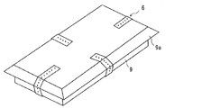
- the adhesive tape 6 fixes a container body 9 used for a lunch box sold at a convenience store or the like and its lid 9a.
- the lid is larger than the container, the central portion of the adhesive tape 6 that is separated from the container main body 9 and the lid 9a is placed on the fingertip or nail from above. It can be easily cut with one hand.
- the cut piece Since the cut piece remains adhered to the container body 9, it does not cling to the hand and does not take time to open.
- the tape is not cut unless a strong local force is applied to the tape center instead of the side edge of the tape. It can be said that it is a suitable adhesive tape.
- FIG. 8 is a plan view of a first modification of the adhesive tape according to the first embodiment.
- the adhesive tape 6 a according to the first modification of Example 1 is provided with a plurality of cuts 7 a in the film base 2.
- the film substrate 2 is a film having a length of 12 mm in the short direction made of cellophane.
- the cut 7a has a length a of 1.0 mm. Since the cellophane film is not easily torn compared to the OPP film, the length a of the cut 7a is set to be longer than the length a of the cut 7.
- the angle ⁇ of the cut 7a is 30 degrees and ⁇ 30 degrees. In the notches 7a, the angles ⁇ of 30 degrees and ⁇ 30 degrees are alternately repeated to form the notch array 8a.
- Other configurations are the same as those of the adhesive tape 6 of the first embodiment.
- action and effect of the adhesive tape 6a are demonstrated.
- the angle ⁇ of the cut 7a is alternately changed. Therefore, even when a position slightly deviated from the center toward both ends is pushed, the cut 7a closest to the position is pressed. Expands and the adhesive tape 6a is cut. Therefore, the ease of cutting does not change significantly even when compared with the case of pressing near the center in the short direction.
- the pressure-sensitive adhesive tape 6 of Example 1 when the pressing position is deviated to the left from the center in the short direction, the cut 7 is more difficult to expand than when deviated to the right.
- the pressure-sensitive adhesive tape 6a according to the first modification of the first embodiment has the same functions and effects as the pressure-sensitive adhesive tape 6 according to the first embodiment.
- the upper end of the adhesive tape 6a has shown the cut end when it cuts by pushing.
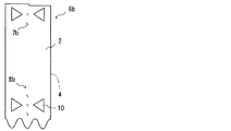
- FIG. 9 is a plan view of a second modification of the adhesive tape according to the first embodiment.
- the adhesive tape 6 b according to the second modification of Example 1 is provided with a plurality of cuts 7 b in the film base 2.
- the film substrate 2 is a film having a length of 12 mm in the short direction made of acetate.
- the adhesive tape 6b is a line in which a plurality of (three) cuts 7b are continuous with the film substrate 2 at equal intervals, and then the portions without the cuts 7b are connected at a constant length, and this combination is repeated.
- a notch array 8b is formed.
- the length a and the interval b of the notches 7b are the same as those of the notches 7, and penetrate through the film base 2.
- the cut angle ⁇ is ⁇ 30 degrees.
- the length a and the number of the notches 7b and the length of the portion without the notches 7b can be freely changed.
- a cut position mark 10 is provided on each side of the three continuous cuts 7b across the central cut 7b.
- the cut position mark 10 has a triangular shape, but is not limited to this shape. Other configurations are the same as those of the adhesive tape 6 of the first embodiment.
- the upper end of the adhesive tape 6b has shown the cut end when it cuts by pushing.
- the pressure-sensitive adhesive tape 6b which is the second modification of the first embodiment, has the effect of being cut by pressing the position where the cut 7b is formed, but is not cut when the portion without the cut 7b is pressed.
- the notch position mark 10 is provided on the adhesive tape 6b, cutting is always performed around the notch 7b by pressing this mark. For this reason, it has the effect that the adhesive tape 6b can be cut
- the pressure-sensitive adhesive tape 6b according to the second modification of the first embodiment has the same operations and effects as the pressure-sensitive adhesive tape 6 according to the first embodiment.
- the adhesive tape which concerns on Example 1 is not limited to the structure shown in a present Example.
- the cut length a and the interval b may be values other than those described in Table 3.
- the length a may be 0.3 mm or more and 3 mm or less, and 2 mm or less is preferable.
- the interval b may be at least 1 times the notch length a and at least 2 mm. The basis for these dimensions has already been described in the section of means for solving the problem.
- FIG. 10 is a plan view of the adhesive tape according to the second embodiment.
- the distance e in the longitudinal direction between the upper end and the upper end of the cut 3b is as shown in FIG. 2B (hereinafter the same in Table 5). Note that the present invention is not limited by this illustration.
- the adhesive tape 11 according to Example 2 is provided with a plurality of cuts 12 in the film base 2 to form a cut array 13.
- the cut array 13 is provided in the range of 2/3 of the length from the center in the short direction of the film base 2 to both side edges.
- the film substrate 2 is a film having a length of 18 mm in the short direction made of OPP.
- the notches 12 have a length a of 0.8 mm, and are provided in two rows at an equal interval b of 5 mm along the longitudinal direction of the adhesive tape 11 at the center in the short direction of the film base 2. Each row is separated by 3 mm in the direction away from the center in the short direction of the film substrate 2. That is, the interval c (see FIG.
- the same applies hereinafter is 6 mm.
- the interval d (see FIG. 2B, the same applies hereinafter) is 2.1 mm
- the interval e (see FIG. 2B, the same applies hereinafter) is 2.9 mm
- the notch array 13 is a staggered array.
- the cutting angle ⁇ is 10 degrees in the left column of FIG. 10 and ⁇ 10 degrees in the right column.
- Other configurations are the same as those of the adhesive tape 6 according to the first embodiment.
- the upper end of the adhesive tape 11 has shown the cut end when it cuts by pushing.
- action of the adhesive tape 11 which concerns on Example 2 is demonstrated. Since the adhesive tape 11 is provided with two rows of cuts 12, even if the pressing position is deviated from the center in the short direction of the adhesive tape 11 to both ends, there are the cuts 12 near the pressed position. The notch 12 is expanded, and as a result, the adhesive tape 11 is cut. In addition, when the space between the rows of the cut array 13 is pushed from above, the cut 12 is expanded and the adhesive tape 11 is similarly cut. This is the same even if the absolute value of the notch angle ⁇ is small.
- the pressure-sensitive adhesive tape 11 according to the second embodiment has the same function as the pressure-sensitive adhesive tape 6 according to the first embodiment.
- the adhesive tape 11 of Example 2 has a length in the short direction of 18 mm, and the width of the tape is slightly wide. Therefore, there is a possibility that a force from a fingertip or a nail is applied to a position deviating from the vicinity of the center in the short direction.
- the adhesive tape 11 since the notches 12 are arranged in a staggered manner over two rows, it can be cut stably. Further, even when the absolute value of the cut angle ⁇ is small, cutting is easy. On the other hand, since the absolute value of the angle ⁇ is small, high tensile strength is maintained even though the notches 12 are arranged in two rows.
- the adhesive tape 11 according to Example 2 has the same effect as the adhesive tape 6 according to Example 1.
- FIG. 11 is a plan view of a first modification according to the second embodiment.
- the adhesive tape 11a is provided with a plurality of cuts 12a along the longitudinal direction of the film base 2 to form a cut array 13a.
- the film base 2 is a film having a length in the short direction of 24 mm made of OPP.
- the cuts 12a are continuously provided with a constant interval b of 6 mm.
- a total of three rows are provided, one row at the center in the short direction of the film substrate 2 and 3 mm apart in a direction away from each other vertically from the center row.
- the notch array 13a forms a parallel array in the relationship between the left and right columns.
- the notches 12a in the center row are located in the middle of the notches 12a in the left and right rows in the longitudinal direction. Therefore, the cut array 13a forms a staggered array in the relationship between the center column and the left and right columns.
- the length of the cut 12a is 0.8 mm
- the cut angle ⁇ is 10 degrees in the left column, ⁇ 10 degrees in the center column, and ⁇ 10 degrees in the right column.
- the upper end of the adhesive tape 11a has shown the cut end when it cuts by pushing.
- the length of the adhesive tape 11a in the short direction is wider than that of the adhesive tape 11, but since the cuts 12a are arranged in three rows, the position to be pressed from the vicinity of the center in the short direction is separated. Even in this case, there are many notches 12a distributed around the periphery. Therefore, the notch 12a is expanded and the adhesive tape 11a is cut. Therefore, the adhesive tape 11a can be stably cut despite its wide width.
- the adhesive tape 11a has the same operations and effects as the adhesive tape 11 according to the first modification of the second embodiment.
- FIG. 12 is a plan view of a second modification example according to the second embodiment.
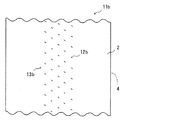
- the adhesive tape 11b is provided with five rows of a plurality of cuts 12b to form a cut array 13b.
- the notches 12b have a length a of 0.8 mm and are continuously provided with a constant interval b of 5 mm.
- the length of the adhesive tape 11b in the short direction is 50 mm.
- the notch arrangement 13b a total of five rows are provided, one on the center and two on each of the left and right rows with a distance of 3 mm and 6 mm away from the center in the short direction of the film base 2.
- the interval d is 0.55 mm
- the interval e is 1.1 mm. Therefore, in the notch array 13b, another notch does not exist in the short direction of the adhesive tape 11b.
- the cut angles ⁇ are all ⁇ 45 degrees.
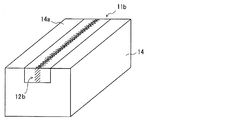
- FIG. 13 is an example of use of the second modification according to the second embodiment, in which the adhesive tape 11b is used for sealing the lid 14a of the cardboard box body 14.
- the cardboard box body 14 and the lid 14a are fixed to each other by an adhesive tape 11b.
- the surface of the adhesive tape 11b attached along the gap between the cardboard box body 14 and the lid 14a is traced while pushing with a nail. Since the distance d of the adhesive tape 11b is 0.55 mm, any notch 12b exists around the gap. When a force is applied to this notch 12b, it expands.
- variety of the transversal direction is as wide as 50 mm
- the adhesive tape 11b cuts a required amount from the wound body 5
- the extension of the notch 12b is obliquely directed toward the side edge. Therefore, in such a case, it is necessary to cut the necessary amount using a conventional instrument.
- the adhesive tape 11b can be easily opened without using a tool when used for temporarily fixing the lid 14a of the cardboard box body 14 or the like. Opening is only traced with a nail, so it doesn't damage the inside when cutting, unlike a cutter. In addition, since only one cut is necessary for cutting the tape to be pushed and cut, the number of cuts can be reduced, and the cutting requires a local force for the cut near the gap, so that the force applied on the surface In this case, it is difficult to cut with an unintended force applied during transportation. As a modification of the adhesive tape 11b, the notch and its peripheral part may be colored so that the location of the notch is known.
- the notch array 13b is loosened with a width of about 3 mm from the center of the adhesive tape 11b to the left and right in the short direction (that is, symbol c in FIG. 2B). It may be arranged so as to meander.
- the adhesive tape which concerns on Example 2 is not limited to the structure shown in a present Example.
- the notch intervals b, c, d, and e may be values other than those described in Table 4.
- interval b should just be 1 time or more of the notch length a, and at least 2 mm or more.
- the interval c is 1.5 times or more of the cut length a, and may be at least 3 mm. The basis for these dimensions has already been described in the section of means for solving the problem.
- FIG. 14 is a plan view of the adhesive tape according to the third embodiment.
- FIG.15 and FIG.16 is a top view of the notch based on the adhesive tape of FIG. 14, respectively. Note that the present invention is not limited by this illustration.
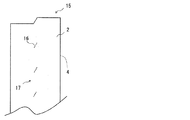
- the pressure-sensitive adhesive tape 15 includes the pressure-sensitive adhesive layer 4 on the back surface of the film base 2 and is provided with perforations 16.
- the film substrate 2 of the adhesive tape 15 is a film having a length of 12 mm in the short direction made of OPP.
- the perforations 16 have a length a of 1.4 mm, and five minute cuts 16p each having a length of 0.2 mm are continuously formed in a perforation shape at intervals of 0.1 mm (see FIG. 15).
- the perforations 16 are provided in a line at the center of the film base 2 in the short direction along the longitudinal direction of the adhesive tape 15 with an equal interval b of 3 mm to form a perforation array 17.
- the angle ⁇ of the perforation 16 is 30 degrees.
- Other configurations are the same as those of the adhesive tape 6 according to the first embodiment (see FIG. 6).
- the upper end of the adhesive tape 15 has shown the cut end when it cuts by pushing.
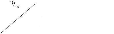
- FIG. 16 shows a cut 16a to which perforations are connected.
- the length a of the cut 16a is 1.4 mm.
- each minute notch 16p tends to be more difficult to expand with respect to the pulling in the longitudinal direction of the adhesive tape 15 than 16a connected with perforations.
- the action of the pressure-sensitive adhesive tape 15 provided with the notches 16a is the same as that of the pressure-sensitive adhesive tape 6 of the first embodiment.
- the effect of the adhesive tape 15 according to the third embodiment will be described.
- the minute notches 16p constituting the perforation 16 are easily connected by a pressing force from above, and become the notches 16a. Since the small cut 16p tends to be difficult to expand by itself, the adhesive tape 15 has a higher tensile strength. That is, the perforation 16 can make the tensile strength stronger than a notch that is not perforated like the notch 7 (see FIG. 6) of the adhesive tape 6 according to the first embodiment. Therefore, it is possible to maintain a sufficient tensile strength even if the angle ⁇ of the perforation is increased.
- the effect of the adhesive tape 15 provided with the perforation 16 is the same as that of the adhesive tape 6 of Example 1.
- FIG. 17 is a plan view schematically showing the notch of the first modification of the third embodiment, but it is not necessarily as shown in this figure.
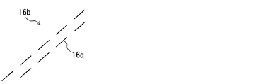
- the perforation set 16b according to the first modified example is one in which minute notches 16q are arranged in parallel in two rows with an interval of 0.1 mm.
- the perforation set 16b is easier to expand than the perforation 16 because the minute notches 16q are connected even between two rows by the force from above.
- the length of the minute notches 16q constituting the perforation set 16b is as short as 16p, it is difficult to expand against the pulling force. Therefore, the tensile strength is not greatly affected.
- the number of columns needs to be determined in consideration of the unintended force and the ease of disconnection from the wound body 5 as the number of columns increases.
- FIG. 18 is a plan view schematically showing a cut in the second modification of the third embodiment, but it does not necessarily have to be as shown in this figure.
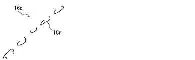
- the perforation 16 c according to the second modification is a continuous series of minute irregular notches 16 r of 0.2 mm with an interval of 0.1 mm.
- the perforation 16c is formed by arranging five sharp needles having a diameter of 0.3 mm so that the angle with respect to the longitudinal direction of the film substrate 2 is 30 degrees and inserting the needles into the film substrate 2.
- the other configuration is the same as that of the perforation 16, and the action is the same as that of the perforation 16.
- the perforation 16c is formed from minute irregular shaped cuts 16r, so that the cutting ability varies, but the irregular shaped cuts 16r can be formed by other protrusions of sharp needles. Simpleness is a big advantage.
- the effect of the perforation 16c is the same as that of the perforation 16.
- FIGS. 19 to 28 and Table 5 The pressure-sensitive adhesive tape of Example 4 according to the embodiment of the present invention will be described in detail with reference to FIGS. 19 to 28 and Table 5 (mainly corresponding to claim 4).
- the components shown in FIGS. 1 to 18 are denoted by the same reference numerals, and the description thereof is omitted.
- the configuration of the adhesive tape 18 according to Example 4 will be specifically described with reference to FIG. 19 and Table 5.
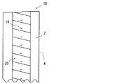
- FIG. 19 is a plan view of the adhesive tape according to the fourth embodiment. Note that the present invention is not limited by this illustration.
- the adhesive tape 18 according to Example 4 is provided with a plurality of slits 19 in the film base 2.
- the film base 2 of the present embodiment is a film having a length of 9 mm in the short direction made of OPP.
- the film base 2 is provided with a portion not provided with the adhesive layer 4 (indicated by hatching in the figure, the same in the following figures). This portion is within a range of about 2/3 from the center in the short direction of the adhesive tape 18 toward both side edges.
- the notches 19 have a length a of 2 mm, and are provided in a line at the center of the film base 2 in the short direction at an equal interval of 2 mm along the longitudinal direction of the adhesive tape 18 to form a notch array 20. .
- the angle ⁇ of the cut 19 is 60 degrees.
- the upper end of the adhesive tape 18 has shown the cut end when it cuts by pushing.
- FIG. 20 is a usage example of the adhesive tape according to the fourth embodiment.
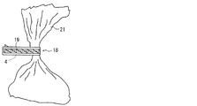
- the adhesive tape 18 binds the opening of the bag 21.
- the end portions of the adhesive tape 18 adhere the adhesive tapes 18 so as not to peel off without adhering to the bag 21.
- the hatched portion not provided with the adhesive layer 4 is not adhered to the bag 21.
- the adhesive tape surface near the boundary between the adhesive tape 18 and the bag 21 is pushed with a nail of the thumb from above while pulling the bound portion of the adhesive tape 18 and the bag 21, the cut 19 is not adhered. Expand.
- the adhesive tape 18 Since the side edge portion of the adhesive tape 18 adheres to the binding portion of the bag 21 that is folded several times, the adhesive tape 18 is pulled in the longitudinal direction when the binding portion is handled so as to be widened. . Accordingly, the cut 19 extends toward the side edge, and the adhesive tape 18 is cut. The operation when the necessary amount of the adhesive tape 18 is cut from the wound body 5 is the same as that of the adhesive tape 6 according to the first embodiment.
- the adhesive tape 18 can be easily cut when it is used as a binding tape.
- Conventional adhesive tape for bundling is almost impossible to cut by hand, and because of its strong adhesive force, it was almost impossible to peel it off. It will be solved.
- a strong force is applied to the adhesive tape 18 in the longitudinal direction at the time of binding, but the tensile strength can be adjusted by appropriately setting the length a of the cut 19 and the cut angle ⁇ . Therefore, it is difficult to cut carelessly during binding, and binding is unlikely to fail.
- it has the same effect as the adhesive tape 6 according to the first embodiment.
- FIG. 21 is a use state diagram of the first modification example according to the fourth embodiment
- FIG. 22 is a use condition diagram of the second modification example according to the fourth embodiment.
- the pressure-sensitive adhesive tape 18a according to the first modification of the present embodiment repeatedly provides a portion not including the pressure-sensitive adhesive layer 4 having a desired length in the longitudinal direction. The length of the portion not provided with the adhesive layer 4 may be determined depending on the application. Further, in this modification, a portion not provided with the adhesive layer 4 is formed in the entire short direction, but a portion having no adhesive layer 4 in a part in the short direction as in Example 4 may be used. Good.
- the film base 2 is provided with a plurality of cuts 19a.
- the film base 2 of the present embodiment is a film having a length in the short direction of 18 mm made of OPP.
- the cuts 19a have a length a of 0.8 mm, and are provided in a line at the center in the short direction of the film base 2 at a uniform interval of 3 mm along the longitudinal direction of the adhesive tape 18a.
- the angle ⁇ of the cut 19a is 30 degrees.
- the portion not provided with the adhesive layer 4 is in the range of 6 cm in length along the longitudinal direction.
- the presence or absence of the adhesion layer 4 can be clarified by coloring the transparent film substrate 2 and the adhesion layer 4.
- the adhesive tape 18b which concerns on the 2nd modification of a present Example is provided with the fixed length part without the notch 19b.
- the portion without the notch 19b includes the adhesive layer 4.
- Other configurations are the same as those of the adhesive tape 18a.
- the operation of the adhesive tape 18a and the adhesive tape 18b will be described.
- the part which does not have the adhesion layer 4 is located between the binding material 21a and the binding material 21a.
- the cut 19a in this portion is not adhered to the bundle 21a, so by pressing the center of the tape with a fingertip or nail, the nearby cut 19a expands and extends to the side end of the adhesive tape 18a.
- the adhesive tape 18a is cut.
- the bound material 21a changes flexibly, even if the center of the tape is pushed, the bound material 21a is deformed, and the force for pulling the tape does not act, so that it cannot be cut.
- the index finger and the middle finger can be cut by placing the index finger and the middle finger between the adhesive tape 18a and the bundle 21a and pressing the adhesive tape 18a with the tip of the thumb or the nail while pulling the adhesive tape 18a forward. Then, as shown in FIG. 22, in the adhesive tape 18b, the part which does not have the adhesive layer 4 is located in the binding material 21a. For example, in the case where the bundle 21a does not have flexibility, even if the cut 19b is pushed from above, the bundle 21a becomes a support without being recessed and the cut 19b does not expand, so the adhesive tape 18b is not cut.
- the bundle 21a is easily changed in shape like a pack containing air together with food such as a wiener bag, it is possible to insert an index finger and a middle finger between the adhesive tape 18b and the bundle 21a. It is. In this way, when the center of the tape is pushed with the tip of the thumb, the cut 19b expands and the adhesive tape 18b is cut. Thereafter, the binding can be released by grasping and peeling off the cut end without the adhesive layer 4.
- Both of the adhesive tape 18a and the adhesive tape 18b are suitable for bundling of a pack or the like having flexibility that contains air together with food like a Wiener bag. In this case, regardless of the position of the portion not provided with the adhesive layer 4, it can be easily cut with a finger without using an instrument. In particular, as shown in FIG. 22, when the portion of the adhesive tape 18 b that does not have the adhesive layer 4 is in close contact with the bundle 21 a, the cut 19 b does not have the adhesive layer 4 and is pushed by the pack containing air.
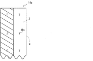
- FIG. 23 is a plan view of a third modification example according to the fourth embodiment
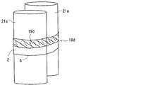
- FIG. 24 is a use state diagram of the fourth modification example according to the fourth embodiment.
- the adhesive tape 18c according to the third modification of the present embodiment is provided with a plurality of perforations 19c on the film base 2.
- Other configurations are shown in Table 5.
- the part not provided with the adhesive layer 4 is a part that occupies from the center in the short direction of the adhesive tape 18c to one side edge. Furthermore, as shown in FIG.
- the adhesive tape 18d according to the fourth modification of the present embodiment is one in which the notch on the side where the adhesive layer 4 is provided is omitted from the perforation 19c of the adhesive tape 18c. However, only the perforation 19d is provided. Other configurations are the same as those of the adhesive tape 18c. In FIG. 24, the bundle 21a is bundled using the adhesive tape 18d.
- the adhesive tape 18c and the adhesive tape 18d will be described.
- the adhesive tape 18c is used for temporary fixing
- the perforation 19c provided in the portion of the adhesive tape 18c that does not include the adhesive layer 4 is pressed, the perforation is connected and cut, and the cut becomes the adhesive layer. Almost reach side edges without 4.
- the adhesive tape 18c can be cut by grasping the part that does not have the adhesive layer 4 and removing the adhesive part. Since the adhesive tape 18d has a portion that does not include the adhesive layer 4 in any part in the longitudinal direction, if there is a gap between the adhesive tape 18d and the bundle 21a, the perforation 19d can be pushed from above so that any Can be cut at a part.
- the index finger and the middle finger are put into the portion of the adhesive tape 18d that does not have the adhesive layer 4 and the vicinity of the perforation 19d is pressed with the tip of the thumb from above, the nearby perforation 19d is connected and cut. It expands and the part which does not have the adhesion layer 4 of the adhesive tape 18d is cut
- the adhesive tape 18c and the adhesive tape 18d use the perforations 19c and 19d instead of the slits, they are superior in tensile strength to the slits.
- the perforation 19c of the part having the adhesive layer 4 in the adhesive tape 18c cannot be used for cutting the adhesive tape 18c once it is adhered to a bundle or the like, but when the necessary length is cut from the wound body 5, It can be cut by pressing because it is not adhered to the surface.
- the adhesive tape 18d has the perforation 19d only on one side, it is better to use a tool when cutting the required length from the wound body 5.
- the adhesive tape 18c and the adhesive tape 18d are excellent in that they can be easily cut at a portion located between the bundles even if the bundles do not change in shape. Further, since any portion in the longitudinal direction does not include the adhesive layer 4, if a gap can be formed between the adhesive tape 18d and the bundle 21a with a finger or the like, the perforation 19d can be pushed, so any Can be cut at the part. Furthermore, since the part which does not have the adhesion layer 4 is parallel to the longitudinal direction of the adhesion tapes 18c and 18d, the application of the adhesion layer 4 is easy.
- FIG. 25 is a plan view of a fifth modification example according to the fourth embodiment.
- the adhesive tape 18e which concerns on the 5th modification of a present Example is provided with the some notch 19e in the film base material 2.
- the film base 2 of the present embodiment is a film having a length in the short direction of 18 mm made of OPP.
- the notches 19e have a length a of 0.8 mm, and are provided in two rows at the center in the short direction of the film substrate 2 with an equal interval b of 5 mm along the longitudinal direction of the adhesive tape 18e.
- Each row is separated by 3 mm in the direction away from the center in the short direction of the film base 2 to form a cut array 20e.
- the angle ⁇ of the cut 19e is 30 degrees on the left side and -30 degrees on the right side.
- the part which does not have the adhesion layer 4 exists in the range of length 1cm along the longitudinal direction of the adhesive tape 18e.
- the upper end of the adhesive tape 18e has shown the cut end when it cuts by pushing.
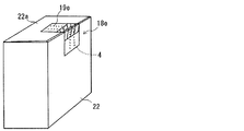
- FIG. 26 is a diagram illustrating a usage state of the fifth modification example according to the fourth embodiment.
- the adhesive tape 18e is used for fixing the box body 22 and the lid 22a, and a portion that does not have the adhesive layer 4 is located in the opening portion of the lid 22a.
- the lid 22a When opening the lid 22a, when the nail is pressed between the box body 22 and the lid 22a from above the adhesive tape 18e, the lid 22a is pushed into the box body 22 by a local force, and the adhesive tape 18e and the lid A space is created between 22a.
- the lid 22a can be opened very easily.
- the lid 22a is slightly recessed inside, but the notch 19e does not expand to that extent, and therefore the lid 22a is not easily opened by an unintended force.
- FIG. 27 is a plan view of a sixth modification example according to the fourth embodiment.
- the adhesive tape 18f according to the sixth modification of the present embodiment is provided with a plurality of cuts 19f in the film base 2.
- the pressure-sensitive adhesive tape 18f of the present example has the same configuration as the pressure-sensitive adhesive tape 11a (see FIG. 11) according to the first modified example of Example 2 except that a portion not having the pressure-sensitive adhesive layer 4 is provided.
- the portion not having the adhesive layer 4 is 2 cm in length along the longitudinal direction, and is within a range of 5/6 from one side in the lateral direction.
- the adhesive tape 18f is provided with the adhesive layer 4 at portions other than the diagonal line on the left side of the adhesive tape 18f, if the adhesive tape 18f is attached to a bundle, the cut 19f is not expanded only by pressing from above, and the adhesive tape 18f is not cut.
- the adhesive tape 18f is used for the purpose of fixing the lid 22a (see FIG. 26)
- the lid 22a is pressed firmly, the lid 22a is pushed into the box 22 and the adhesive layer 4 is peeled off from the lid 22a.
- the adhesive tape 18f is cut in the same manner as the adhesive tape 18e.
- the adhesive tape 18f is used for temporary fixing of the lid 22a and the like similarly to the adhesive tape 18e.
- the adhesive layer 4 is partly provided unlike the adhesive tape 18e, the lid 22a and the box are stronger than the adhesive tape 18e. It is necessary to push between the main bodies 22 with a nail.
- the adhesive tape 18e is fixed stronger than the adhesive tape 18e, the possibility that the adhesive tape 18f is cut during transportation is reduced.
- what is necessary is just to change suitably the area of the part without the adhesive layer 4 so that it may be suitable for actual utilization, and other than FIG.
- it has the same operation and effect as the adhesive tape 11b according to the second modification of the second embodiment.
- FIG. 28 is a plan view of a seventh modification example according to the fourth embodiment.
- the adhesive tape 18g according to the seventh modification of the present embodiment is provided with a plurality of cuts 19g in the film base 2.
- the pressure-sensitive adhesive tape 18g of the present example has the same configuration as the pressure-sensitive adhesive tape 6b (see FIG. 9) according to the second modification example of Example 1 except that a portion not having the pressure-sensitive adhesive layer 4 is provided.
- the portion not having the adhesive layer 4 is within a range of 4 cm in length along the longitudinal direction of the adhesive tape 18g, centering on the portion having the cut 19g.
- the upper end of the adhesive tape 18g shows the cut end when it is cut by pressing.
- the adhesive tape 18g cuts the required length from the wound body 5
- the cut 19g is expanded by pressing the portion indicated by the cut position mark 10 with a fingertip or a nail, and is cut as a result. Since the adhesive tape 18g can be cut only at the cut position mark 10 previously indicated by a triangle, the length of the adhesive tape is constant and there is no waste. Since the cut-off terminal does not have the adhesive layer 4, even if it is attached to an object while holding both terminals, it does not stick to the finger and is easy to apply. Also, since no fingerprints remain, the beauty can be maintained. Further, when the adhesive tape 18g is peeled off, it is easy to peel off by grasping this portion. Therefore, the adhesive tape 18g can be used for temporarily fixing parts of industrial products such as during transportation. In addition, it has the same operation and effect as the adhesive tape 6b according to the second modification of the first embodiment.
- the invention described in claims 1 to 4 can be easily cut by simply pressing the film base of the adhesive tape with a fingertip or a nail, and at the same time maintains the tensile strength in the longitudinal direction of the adhesive tape. It can also be applied as an adhesive tape for packing articles used for pasting paper and the like, and as a binding adhesive tape used for fixing containers and lids, binding bundles of food packs, and the like.
- Notch 19c Perforated 19d ... Perforation 19e ... Notch 19f ... Notch 19g ... Notch 20 ... Notch array 20a ... Notch array 20e ... Notch array 21 ... Bag 21a ... Bundled item 22 ... Box body 22a ... Lid ⁇ ... Notch angle a ... Length of notch b: Distance between notches in the longitudinal direction of the same row c: Distance between rows of notches d: Distance between longitudinal ends of notches existing in different rows e: Distance between upper ends and upper ends of notches existing in different rows Longitudinal spacing
Landscapes
- Chemical & Material Sciences (AREA)
- Organic Chemistry (AREA)
- Adhesive Tapes (AREA)
Applications Claiming Priority (2)
| Application Number | Priority Date | Filing Date | Title |
|---|---|---|---|
| JP2012-009340 | 2012-01-19 | ||
| JP2012009340A JP5105651B2 (ja) | 2011-01-20 | 2012-01-19 | 押して切る粘着テープ |
Publications (1)
| Publication Number | Publication Date |
|---|---|
| WO2013108432A1 true WO2013108432A1 (fr) | 2013-07-25 |
Family
ID=48799826
Family Applications (1)
| Application Number | Title | Priority Date | Filing Date |
|---|---|---|---|
| PCT/JP2012/069611 Ceased WO2013108432A1 (fr) | 2012-01-19 | 2012-08-01 | Ruban adhésif à presser pour couper |
Country Status (1)
| Country | Link |
|---|---|
| WO (1) | WO2013108432A1 (fr) |
Citations (7)
| Publication number | Priority date | Publication date | Assignee | Title |
|---|---|---|---|---|
| US3467250A (en) * | 1968-01-25 | 1969-09-16 | Anthony N D Elia | Easy tear tape with lift tab |
| JPS508153U (fr) * | 1973-05-24 | 1975-01-28 | ||
| US4581087A (en) * | 1983-02-04 | 1986-04-08 | The Kendall Company | Method of making a thermoplastic adhesive-coated tape |
| JPH03106333U (fr) * | 1990-02-19 | 1991-11-01 | ||
| US5198276A (en) * | 1991-02-15 | 1993-03-30 | Fujio Nakajima | Paper products having perforations and perforate pattern |
| JP2000297262A (ja) * | 1999-04-15 | 2000-10-24 | Tm Adotekku:Kk | 手切れ性の良好な結束用材 |
| JP2004505799A (ja) * | 2000-08-08 | 2004-02-26 | スリーエム イノベイティブ プロパティズ カンパニー | 布様ポリマーフィルム |
-
2012
- 2012-08-01 WO PCT/JP2012/069611 patent/WO2013108432A1/fr not_active Ceased
Patent Citations (7)
| Publication number | Priority date | Publication date | Assignee | Title |
|---|---|---|---|---|
| US3467250A (en) * | 1968-01-25 | 1969-09-16 | Anthony N D Elia | Easy tear tape with lift tab |
| JPS508153U (fr) * | 1973-05-24 | 1975-01-28 | ||
| US4581087A (en) * | 1983-02-04 | 1986-04-08 | The Kendall Company | Method of making a thermoplastic adhesive-coated tape |
| JPH03106333U (fr) * | 1990-02-19 | 1991-11-01 | ||
| US5198276A (en) * | 1991-02-15 | 1993-03-30 | Fujio Nakajima | Paper products having perforations and perforate pattern |
| JP2000297262A (ja) * | 1999-04-15 | 2000-10-24 | Tm Adotekku:Kk | 手切れ性の良好な結束用材 |
| JP2004505799A (ja) * | 2000-08-08 | 2004-02-26 | スリーエム イノベイティブ プロパティズ カンパニー | 布様ポリマーフィルム |
Similar Documents
| Publication | Publication Date | Title |
|---|---|---|
| US9139344B2 (en) | Packing tape | |
| JP5952369B2 (ja) | 粘着テープ及び粘着テープ巻回体並びにテープディスペンサー | |
| JP2002177316A (ja) | 二重瞼形成用テープまたは糸及びその製造方法 | |
| JP5105651B2 (ja) | 押して切る粘着テープ | |
| JP2009007428A (ja) | 延伸剥離テープ | |
| JP2014012804A (ja) | 保護シート材と表面保護シートの貼付方法 | |
| US9597239B2 (en) | Elongated strip-like film bandage | |
| EP3037014A1 (fr) | Bande cosmétique de régénération des paupières et son procédé de fabrication | |
| CN203159520U (zh) | 易撕胶带及易撕胶带组件 | |
| US8739804B2 (en) | Removal mechanism for adhesive eye strips | |
| JP2000297262A (ja) | 手切れ性の良好な結束用材 | |
| WO2013108432A1 (fr) | Ruban adhésif à presser pour couper | |
| JP4494006B2 (ja) | 結束用ラベル連続体。 | |
| JP4723357B2 (ja) | 仮止用ラベルの使用方法 | |
| JP2010122544A (ja) | タグ用ラベル | |
| KR200480177Y1 (ko) | 절취홀이 형성된 접착테이프 | |
| JP4949434B2 (ja) | ラベルシート | |
| JP6016296B2 (ja) | 片面粘着テープ及び片面粘着テープ引き出し装置 | |
| JP6403958B2 (ja) | ブリスター包装体 | |
| JP5973179B2 (ja) | 粘着テープロール | |
| JP3966854B2 (ja) | 結束用テープ | |
| JP2000303031A (ja) | 積層粘着テ−プ | |
| JP3148571U (ja) | 物品包装単体の連結体及びラベル | |
| JP7406342B2 (ja) | 二重瞼形成用シート | |
| JP6694024B2 (ja) | シール・ロール |
Legal Events
| Date | Code | Title | Description |
|---|---|---|---|
| 121 | Ep: the epo has been informed by wipo that ep was designated in this application |
Ref document number: 12865648 Country of ref document: EP Kind code of ref document: A1 |
|
| NENP | Non-entry into the national phase |
Ref country code: DE |
|
| 122 | Ep: pct application non-entry in european phase |
Ref document number: 12865648 Country of ref document: EP Kind code of ref document: A1 |