WO2013108461A1 - Système médical - Google Patents
Système médical Download PDFInfo
- Publication number
- WO2013108461A1 WO2013108461A1 PCT/JP2012/077842 JP2012077842W WO2013108461A1 WO 2013108461 A1 WO2013108461 A1 WO 2013108461A1 JP 2012077842 W JP2012077842 W JP 2012077842W WO 2013108461 A1 WO2013108461 A1 WO 2013108461A1
- Authority
- WO
- WIPO (PCT)
- Prior art keywords
- output
- sound
- medical device
- unit
- volume
- Prior art date
- Legal status (The legal status is an assumption and is not a legal conclusion. Google has not performed a legal analysis and makes no representation as to the accuracy of the status listed.)
- Ceased
Links
Images



Classifications
-
- H—ELECTRICITY
- H03—ELECTRONIC CIRCUITRY
- H03G—CONTROL OF AMPLIFICATION
- H03G3/00—Gain control in amplifiers or frequency changers
- H03G3/20—Automatic control
-
- A—HUMAN NECESSITIES
- A61—MEDICAL OR VETERINARY SCIENCE; HYGIENE
- A61B—DIAGNOSIS; SURGERY; IDENTIFICATION
- A61B18/00—Surgical instruments, devices or methods for transferring non-mechanical forms of energy to or from the body
- A61B18/04—Surgical instruments, devices or methods for transferring non-mechanical forms of energy to or from the body by heating
- A61B18/12—Surgical instruments, devices or methods for transferring non-mechanical forms of energy to or from the body by heating by passing a current through the tissue to be heated, e.g. high-frequency current
- A61B18/1206—Generators therefor
- A61B18/1233—Generators therefor with circuits for assuring patient safety
-
- A—HUMAN NECESSITIES
- A61—MEDICAL OR VETERINARY SCIENCE; HYGIENE
- A61B—DIAGNOSIS; SURGERY; IDENTIFICATION
- A61B5/00—Measuring for diagnostic purposes; Identification of persons
- A61B5/24—Detecting, measuring or recording bioelectric or biomagnetic signals of the body or parts thereof
-
- A—HUMAN NECESSITIES
- A61—MEDICAL OR VETERINARY SCIENCE; HYGIENE
- A61B—DIAGNOSIS; SURGERY; IDENTIFICATION
- A61B18/00—Surgical instruments, devices or methods for transferring non-mechanical forms of energy to or from the body
- A61B18/04—Surgical instruments, devices or methods for transferring non-mechanical forms of energy to or from the body by heating
- A61B18/12—Surgical instruments, devices or methods for transferring non-mechanical forms of energy to or from the body by heating by passing a current through the tissue to be heated, e.g. high-frequency current
- A61B18/14—Probes or electrodes therefor
-
- A—HUMAN NECESSITIES
- A61—MEDICAL OR VETERINARY SCIENCE; HYGIENE
- A61B—DIAGNOSIS; SURGERY; IDENTIFICATION
- A61B17/00—Surgical instruments, devices or methods
- A61B2017/00017—Electrical control of surgical instruments
- A61B2017/00115—Electrical control of surgical instruments with audible or visual output
- A61B2017/00119—Electrical control of surgical instruments with audible or visual output alarm; indicating an abnormal situation
-
- A—HUMAN NECESSITIES
- A61—MEDICAL OR VETERINARY SCIENCE; HYGIENE
- A61B—DIAGNOSIS; SURGERY; IDENTIFICATION
- A61B17/00—Surgical instruments, devices or methods
- A61B17/32—Surgical cutting instruments
- A61B17/320068—Surgical cutting instruments using mechanical vibrations, e.g. ultrasonic
- A61B2017/320069—Surgical cutting instruments using mechanical vibrations, e.g. ultrasonic for ablating tissue
-
- A—HUMAN NECESSITIES
- A61—MEDICAL OR VETERINARY SCIENCE; HYGIENE
- A61B—DIAGNOSIS; SURGERY; IDENTIFICATION
- A61B18/00—Surgical instruments, devices or methods for transferring non-mechanical forms of energy to or from the body
- A61B2018/00571—Surgical instruments, devices or methods for transferring non-mechanical forms of energy to or from the body for achieving a particular surgical effect
- A61B2018/00589—Coagulation
-
- A—HUMAN NECESSITIES
- A61—MEDICAL OR VETERINARY SCIENCE; HYGIENE
- A61B—DIAGNOSIS; SURGERY; IDENTIFICATION
- A61B18/00—Surgical instruments, devices or methods for transferring non-mechanical forms of energy to or from the body
- A61B2018/00571—Surgical instruments, devices or methods for transferring non-mechanical forms of energy to or from the body for achieving a particular surgical effect
- A61B2018/00595—Cauterization
-
- A—HUMAN NECESSITIES
- A61—MEDICAL OR VETERINARY SCIENCE; HYGIENE
- A61B—DIAGNOSIS; SURGERY; IDENTIFICATION
- A61B18/00—Surgical instruments, devices or methods for transferring non-mechanical forms of energy to or from the body
- A61B2018/00636—Sensing and controlling the application of energy
- A61B2018/00898—Alarms or notifications created in response to an abnormal condition
Definitions
- the present invention relates to a medical system, and more particularly to a medical system including a plurality of medical devices each having a sound output function.
- an ultrasonic output device that is a device for performing incision and coagulation of biological tissue may be used together with a high-frequency output device.
- the ultrasonic output device is a device that performs a treatment on a living tissue to be treated by ultrasonic vibration
- the high-frequency output device is a device that performs the treatment by high-frequency current.
- some medical devices have a function to output sound. For example, when the surgeon depresses an energy output instruction switch for treatment and outputs energy, the medical device informs or recognizes that the surgeon is outputting the treatment energy. A predetermined sound is output at a predetermined volume. Such a sound output function is provided for each apparatus, and the volume setting is performed for each apparatus.
- the output volume of the sound from the speaker is set for each medical device, and the multiple medical devices are not linked or linked with respect to the output volume level.
- the output volume level of another medical device is not changed. Therefore, if the output volume level changed in one medical device is lower than the output volume level of the sound output from the other medical device, when the sound of the other medical device is output, the changed one There is a possibility that the surgeon cannot recognize the sound output from the medical device.
- the present invention has been made in view of the above problems, and an object thereof is to provide a medical system capable of interlocking or linking output volume levels between a plurality of medical devices.
- a medical system is a medical system including a first medical device and a second medical device, and is provided in each of the first medical device and the second medical device, and the predetermined medical system.
- An output state detection unit that detects an output state of each of the outputs, and a sound corresponding to the output state that is provided in each of the first medical device and the second medical device and is detected by the output state detection unit Is output from the sound output unit according to the output state detected by the output state detection unit, provided in each of the first medical device and the second medical device.
- a first output that is provided in one of the first medical device and the second medical device and that transmits output volume information about the sound to the other.
- a volume information transmitting unit A first output volume that is provided on the other of the medical device and the second medical device, receives the output volume information transmitted from the first output volume information transmission unit, and transmits the output volume information to the sound output control unit And a sound output control unit of the other medical device based on the output volume information from the first output volume transmission unit received by the first output volume information reception unit. And controlling the output volume of the sound output from the sound output unit.
- FIG. 5 is a flowchart showing an example of a flow of setting processing of an output sound volume level when starting the high-frequency output device 12 and the ultrasonic output device 15 according to the embodiment of the present invention.
- FIG. 1 is a configuration diagram showing a configuration of a surgical system according to an embodiment of the present invention.
- the surgical system 1 is a medical system that includes a high-frequency treatment device 2 and an ultrasonic treatment device 3.
- the high-frequency treatment device 2 is a medical device having a handpiece 11 as a treatment tool that performs a treatment on a living tissue to be treated with a high-frequency current, and a high-frequency output device 12 that outputs a high-frequency current to the handpiece 11.
- the ultrasonic therapy apparatus 3 is an ultrasonic wave for ultrasonically vibrating a handpiece 14 as a treatment tool for performing a treatment on a living tissue to be treated by ultrasonic vibration, and an ultrasonic vibrator built in the handpiece 14. It is a medical device having an ultrasonic output device 15 that outputs a drive signal.
- the high-frequency output device 12 and the ultrasonic output device 15 are connected by a communication cable 16 so that mutual data communication is possible.
- the handpiece 11 is a treatment instrument having a grip portion 11a, a sheath portion 11b extending from the grip portion 11a toward the distal end, and a treatment portion (not shown) provided at the distal end portion of the sheath portion 11b.
- the cable 11c extends from the rear end side of the grip portion 11a, and the handpiece connector 11d at the rear end of the cable 11c is detachable from the output connector of the high-frequency output device 12.
- a foot switch 17 for instructing high frequency output is connected to the high frequency output device 12 via a cable 17a. The surgeon can perform a treatment with a high-frequency current in the treatment portion of the handpiece 11 by pressing and operating the foot switch 17.
- the handpiece 14 is provided at a gripping portion 14a provided with a switch (not shown) for instructing ultrasonic output, a sheath portion 14b extending from the gripping portion 14a to the distal end side, and a distal end portion of the sheath portion 14b.
- a treatment tool (not shown).
- the cable 14c extends from the rear end side of the gripping portion 14a, and the handpiece connector 14d at the rear end of the cable 14c is detachable from the output connector of the ultrasonic wave output device 15. The surgeon can perform treatment by ultrasonic vibration in the treatment portion of the handpiece 14 by pressing and operating a switch (not shown) provided on the handpiece 14.
- the ultrasonic output device 15 receives a high-frequency output that is a high-frequency current signal from the high-frequency output device 12, and can simultaneously output a high-frequency signal and an ultrasonic drive signal. Therefore, two high-frequency cables for transmitting high-frequency signals are also inserted in the cable 14c.
- the high-frequency output device 12 and the ultrasonic output device 15 have speakers 18 and 19, respectively.
- the high-frequency output device 12 and the ultrasonic output device 15 output a predetermined sound from the speakers 18 and 19 when the high-frequency output and the ultrasonic output are being output, respectively.
- the high frequency output device 12 and the ultrasonic output device 15 are provided with touch panels 20 and 21 having liquid crystal display devices (LCD), respectively, so that various information can be displayed, instructed and set.
- LCD liquid crystal display devices
- FIG. 2 is a block diagram showing the configuration of the high-frequency output device 12.
- a high-frequency output device 12 which is a therapeutic device for performing treatment on a subject, includes a waveform generation circuit 21 for generating a sine wave and a burst wave, and a sine wave or burst wave output from the waveform generation circuit 21. The signal is input to the amplifier 23 via the resonance circuit 22.
- the signal amplified by the amplifier 23 is applied to the primary winding side of the output transformer 24, and a high frequency signal which is a high frequency output for cauterization is generated on the secondary winding side.
- the secondary winding of the output transformer 24 is connected to, for example, four output connectors 26a, 26b, 26c, and 26d and a docking connector 26e via a relay switching circuit 25 that switches an output high-frequency signal.
- the docking connector 26e is a female connector and is connected to a male docking connector 46c of the ultrasonic output device 15 described later.
- the docking connector 26 e is provided on the bottom plate of the housing of the high frequency output device 12.
- the resonance circuit 22 is supplied with a power supply voltage from a voltage variable power supply circuit 27, and the waveform generation circuit 21 and the power supply circuit 27 are controlled by a central processing unit (hereinafter referred to as CPU) 28 as a control unit.
- the CPU 28 controls the waveform generation circuit 21 and the power supply circuit 27 in accordance with the output mode setting, the output set value, and the like.
- the output signal of the secondary winding of the output transformer 24 is input to the voltage detection circuit 29a and the current detection circuit 29b that constitute the detection unit 29.
- the voltage detection circuit 29a and the current detection circuit 29b detect or measure the voltage and current of the high-frequency signal output from the secondary winding of the output transformer 24.
- the detected voltage and current signals are converted into digital voltage signals and current signals by analog-digital converters (hereinafter referred to as A / D converters) 30a and 30b, respectively, and input to the CPU.
- a / D converters analog-digital converters
- the CPU 28 detects or calculates the high frequency power of the product from the input voltage signal and current signal. Then, the CPU 28 controls the power supply voltage of the power supply circuit 27 so that the value of the detected high frequency power becomes a preset setting value.
- the CPU 28 is connected to the communication connector 32 via a communication circuit 31 that performs communication.
- the communication connector 32 is connected to the communication connector 50 on the ultrasonic output device 15 side shown in FIG.
- the docking connector 26e connected to the relay switching circuit 25 is detachably connected to the docking connector 46c which is a male connector on the ultrasonic output device 15 side.
- connection detection connector pins in the docking connector 26e are connected to the docking connector connection detection circuit 33.
- the docking connector connection detection circuit 33 is connected to the docking connector 26e by using the connection detection connector pin.
- the connection with the docking connector 46c of the sound wave output device 15 is always detected.
- the two connection detection connector pins are set so as to be connected to, for example, two short-circuited connector pins on the other docking connector 46c side. Therefore, it is possible to detect whether or not the two docking connectors 26e and 46c are connected by detecting whether or not the two connection detection connector pins are in a conductive state.
- connection detection result by the docking connector connection detection circuit 33 is transmitted to the CPU 28.
- the CPU 28 prohibits simultaneous output of ultrasonic output and high frequency output. In other words, the CPU 28 permits simultaneous output of the ultrasonic output and the high frequency output only when the connection of the docking connectors 26e and 46c is detected.
- the docking connector connection detection circuit 33 detects the connection between the two docking connectors 26e and 46c, and outputs or outputs from the output transformer 24 when simultaneous output of ultrasonic output and high frequency output is instructed or set.
- the relay switching circuit 25 is switched so that a signal is output to the docking connector 26e side.
- the CPU 28 may control the switching instead of the docking connector connection detection circuit 33. Furthermore, an operation signal from the foot switch 17 is input to the CPU 28 via a connector 34 to which the cable 17a is connected.
- the speaker 18 of the high-frequency output device 12 is driven by the sound source circuit 35 under the control of the CPU 28.
- the CPU 28 controls the sound source circuit 35 so as to output a sound corresponding to the high frequency output at a predetermined output volume level while the instruction is given. To do.
- the CPU 28 controls the sound source circuit 35 so that a sound indicating the occurrence of the error is output at a predetermined output volume level during the error output.
- the CPU 28 constitutes an output state detection unit that detects an output state of a predetermined output such as an energy output and an error output. When the predetermined output is detected, a sound corresponding to the output is output to a predetermined output volume. Output by level.
- the CPU 28 configures a sound output control unit that controls the output of the sound output from the speaker 18 according to the detected output state.
- the speaker 18 comprises the sound output part which outputs the sound according to the detected output state.
- the touch panel 20 of the high-frequency output device 12 outputs an input signal such as an operation signal or a setting signal to the CPU 28 and displays an image on the LCD screen based on the image signal from the CPU 28.
- the user can set the volume of the sound output from the speaker 18 using the screen of the touch panel 20.
- the high frequency output device 12 has a flash memory 36 connected to the CPU 28.
- the flash memory 36 stores a high frequency output control program, an output volume setting program, various setting values, and the like.
- the CPU 28 when the handpiece 11 is connected to the high-frequency output device 12 and the foot switch 17 is pressed, the CPU 28 outputs a high-frequency output of a value designated or set from the output transformer 24 to the output connector to which the handpiece 11 is connected.
- the waveform generation circuit 21 and the power supply circuit 27 are controlled so as to be output from.
- the CPU 28 continues to output a predetermined sound from the speaker 18 when the high frequency output is instructed, that is, while the foot switch 17 is pressed and the energy output is instructed.
- the CPU 28 detects the error and drives the sound source circuit 35 to output a sound corresponding to a predetermined error output from the speaker 18.
- the CPU 28 writes information indicating an error occurrence state in a predetermined storage area of the flash memory 36. For example, when an error occurs in the high-frequency output device 12, the error output is detected by the CPU 28, and the CPU 28 sets a flag 1 indicating that an error has occurred in a predetermined storage area. When the cause of occurrence of the error disappears, no error output is output, so the CPU 28 rewrites the flag written and set in the predetermined area to 0 indicating that no error has occurred. Then, when there is a change in the state of the flag indicating the presence or absence of an error, the CPU 28 performs a process of transmitting flag information to the ultrasonic output device 15 via the communication circuit 31.
- FIG. 3 is a block diagram showing the configuration of the ultrasonic output device 15.
- An ultrasonic output device 15 which is a treatment device for performing treatment on a subject has an output control circuit 41 having a built-in oscillation circuit.
- the output control circuit 41 adjusts the frequency and current of the oscillation signal oscillated by the oscillation circuit and outputs the result to the amplifier 43 under the control of the CPU 42 as a control unit.
- the signal amplified by the amplifier 43 is input to the output circuit 44, voltage amplified by a transformer (not shown) of the output circuit 44, and output as an ultrasonic drive (output) signal from the secondary winding of the transformer.
- the ultrasonic drive signal is output to the two output connectors 46a and 46b via a relay switching circuit 45 that switches and outputs this signal. Note that the gain of the amplifier 43 is controlled by the CPU 42.
- One output connector 46a of the two output connectors is also connected to a docking connector 46c which is a male connector.
- the docking connector 46 c is provided on the top plate of the casing of the ultrasonic output device 15.
- a handpiece capable of monopolar high-frequency current output can be connected to the output connector 46a.
- the ultrasonic output device 15 and the handpiece 14 output a monopolar high-frequency current will be described.
- the ultrasonic output device 15 and the handpiece 14 output a bipolar high-frequency current. Also good.
- the output connector 46b is not connected to the docking connector 46c, but is connected to an ultrasonic handpiece that outputs ultrasonic waves independently of the high-frequency output device 12.
- the ultrasonic drive signal output from the output circuit 44 is input to the voltage detection circuit 47a and the current detection circuit 47b constituting the detection unit 47, and the voltage and current are detected, that is, measured.
- the detected voltage and current are input to the CPU 42 via the A / D converters in the voltage detection circuit 47a and the current detection circuit 47b, respectively.
- the CPU 42 performs constant current control via the output control circuit 41 based on the voltage and current detected by the detection unit 47 so as to output the set power from the output circuit 44.
- the control information of the output value at the time of output from the output circuit 44 is temporarily held in the memory in the output control circuit 41, and the CPU 42 immediately follows the output control circuit 41 through the output control circuit 41 by the detected voltage and current. Control is performed to correct the control information.
- the CPU 42 is connected to the communication connector 50 via a communication circuit 49 that performs communication.
- the communication connector 50 is connected to the communication connector 32 on the high-frequency output device 12 side shown in FIG. Therefore, the CPU 42 and the CPU 28 can transmit and receive each other via the communication cable 16.
- the connector connection detection pins in the two output connectors 46a and 46b are connected to a handpiece connector connection detection circuit (hereinafter referred to as an HP connector connection detection circuit) 51.
- the HP connector connection detection circuit 51 detects connection / non-connection of the handpiece connector 14d to the output connectors 46a, 46b, and outputs the detection result to the CPU 42.
- the CPU 42 switches the relay via the output control circuit 41 so as to supply the output signal (that is, the ultrasonic drive signal) from the output circuit 44 to the output connector to which the handpiece is connected based on the detection result information.
- the switching of the circuit 45 is controlled.
- the CPU 42 may directly control switching of the relay switching circuit 45.
- the ultrasonic output device 15 has a speaker 19 driven by a sound source circuit 52.
- the switch of the handpiece 14 is operated and an instruction for ultrasonic output is given, the CPU 42 outputs a sound corresponding to the ultrasonic output at a predetermined output volume level while the instruction is given.
- the circuit 52 is controlled.
- the CPU 42 controls the sound source circuit 52 so that a sound indicating the occurrence of the error is output at a predetermined output volume level during the error output.
- the CPU 42 constitutes an output state detection unit that detects an output state for a predetermined output such as an energy output and an error output. When the predetermined output is detected, a sound corresponding to the output is output to a predetermined output volume. Output by level.
- the CPU 42 constitutes a sound output control unit that controls the output of the sound output from the speaker 19 in accordance with the detected output state.
- the speaker 19 comprises the sound output part which outputs the sound according to the detected output state.
- the touch panel 21 of the ultrasonic output device 15 outputs input signals such as operation signals and setting signals to the CPU 42 and displays an image on the LCD screen based on the image signal from the CPU 42.
- the user can set the volume of the sound output from the speaker 19 using the screen of the touch panel 21.
- the ultrasonic output device 15 has a flash memory 53 connected to the CPU 42.
- the flash memory 53 stores an ultrasonic output control program, an output volume setting program, various setting values, and the like.
- the output connector to which the handpiece 14 is connected and the HP connector connection detection circuit 51 are connected. Then, an ultrasonic output instruction signal is input to the CPU 42.
- the CPU 42 controls the output control circuit 41 so that an ultrasonic output having a value designated or set from the output circuit 44 is output from the output connector to which the handpiece 14 is connected.
- the CPU 42 When simultaneous output of high frequency output and ultrasonic output is designated or set, when a switch for instructing ultrasonic output (not shown) is pressed, the CPU 42 outputs control circuit 41 for ultrasonic output. And the CPU 28 of the high-frequency output device 12 is instructed to output a high frequency via the communication circuit 49 and the communication cable 16.
- the high frequency output device 12 controls the power supply circuit 27, the waveform generation circuit 21, and the docking connector connection detection circuit 33, The high frequency output of the relay switching circuit 25 is supplied to the ultrasonic output device 15 via the docking connectors 26e and 46c. As a result, an ultrasonic output and a high frequency output are simultaneously output from the output connector 46a.
- the CPU 42 continues to output a predetermined sound from the speaker 19 when the ultrasonic output is instructed, that is, while the switch of the handpiece 14 is pressed and the energy output is instructed.
- the CPU 42 detects the error and drives the sound source circuit 52 to output a predetermined error sound from the speaker 19. At the same time, the CPU 42 writes information indicating an error occurrence state in a predetermined storage area of the flash memory 53. For example, when an error occurs in the ultrasonic output device 15, the error output is detected by the CPU 42, and the CPU 42 sets a flag 1 indicating that an error has occurred in a predetermined storage area. When the cause of occurrence of the error disappears, no error output is output, so the CPU 42 rewrites the flag written and set in the predetermined area to 0 indicating that no error has occurred. Then, when there is a change in the state of the flag indicating the presence or absence of an error, the CPU 42 performs processing for transmitting flag information to the high frequency output device 12 via the communication circuit 49.
- the output volume level which one of the high-frequency output device 12 and the ultrasonic output device 15 is the master device is preset, and the device set or designated as the master device is stored in the flash memory as the master device. Information indicating that it exists is recorded.
- the setting of the master device is performed by, for example, displaying the setting screen on the touch panel and allowing the user to select it.
- the ultrasonic output device 15 will be described below as the master device.
- volume setting in the high-frequency output device 12 and the ultrasonic output device 15 will be described.
- the volume level of the sound output from the speakers 18 and 19, that is, the output volume level can be set.
- FIG. 4 is a diagram showing an example of an output volume setting screen displayed on the touch panels 20 and 21.
- the output volume setting change screen SS of FIG. Displayed on the screen.
- the output volume setting change screen SS may be displayed on the entire screen of the touch panel 20, may be displayed as a part of the screen, or may be displayed as a pop-up window on the screen.
- the output volume setting change screen SS is a level indicating which output volume level is at a level among a plurality of levels, along with display of characters 61 and a speaker icon 62 indicating that the screen is for changing the output volume setting.
- a display unit 63 and an operation button display unit 64 for changing the level are included.
- the operation button display unit 64 includes a + (plus) button 64a and a-(minus) button 64b.
- the level display unit 63 displays the currently set output volume level as a bar level indicating which level of a plurality of levels (here, 10 levels) is present.
- the output volume level is set to level 6; the left six bars with 1-6 white blocks arranged vertically and the right side with 7-10 diagonal blocks arranged vertically This is indicated by the display with four bars.
- the output volume level increases by one level.
- the level display unit 63 has seven bars on the left side in which 1 to 7 white blocks are vertically arranged and 8 to 10 diagonal blocks.
- the display content of the level display section 63 is changed to a state in which three bars on the right side are displayed vertically and the output volume level is set to level 7.
- the output volume level decreases by one level.
- the level display unit 63 has five bars on the left side in which 1 to 5 white blocks are arranged vertically and 6 to 10 diagonal blocks.
- the display content of the level display unit 63 is changed to a state in which five bars on the right side are displayed vertically and the output volume level is set to level 5.
- the CPU 28 When the output volume level is changed, the CPU 28 writes and stores the changed output volume level data in the flash memory 36 and changes the data to the ultrasonic output device 15 via the communication circuit 31. Transmits output volume level data.
- the output volume level of the sound output from the speaker 18 is set by the high frequency output device 12
- the same output volume level of the sound output from the speaker 19 is also set in the ultrasonic output device 15. 12 is changed to the same level as the output volume level changed in setting.
- the user can similarly change the setting of the output volume level of the sound output from the speaker 19 on the touch panel 21 of the ultrasonic output device 15.
- the data of the changed output volume level is written and stored in the flash memory 53 by the CPU 42 and also via the communication circuit 49. Then, the data of the changed output volume level is transmitted to the high-frequency output device 12.
- the output volume level of the sound output from the speaker 19 is set by the ultrasonic output device 15
- the same output volume level of the sound output from the speaker 18 is also output by the ultrasonic output in the high frequency output device 12.
- the output level is changed to the same level as the output volume level changed by the device 15.
- the setting change of the output volume level of the sound output from the speaker is performed in either the high-frequency output device 12 or the ultrasonic output device 15, the same output volume level of the sound output from the speaker is also detected on the other side.
- the output volume level is changed to the same output volume level as the changed setting.
- the output volumes of the sounds output from the two speakers 18 and 19 are the same.
- the output volume level value set in the high-frequency output device 12 and the ultrasonic output device 15 may not match the output volume of the actually output sound.
- the output volume of the sound that is actually output when the high-frequency output device 12 is level 5 may be equal to the output volume of the sound that is actually output when the ultrasonic output device 15 is level 7.
- each of the high-frequency output device 12 and the ultrasonic output device 15 has the corresponding information of the output volume level of itself and the other party, and receives the information of the output volume level changed from the other party. And the other party may change their output volume level based on the correspondence information so that the output volume of the sound actually output by the other party becomes equal.
- FIG. 5 is a flowchart showing an example of the flow of the output volume level setting process when the high-frequency output device 12 and the ultrasonic output device 15 are activated.
- the CPUs 28 and 42 read and execute a startup volume setting program from the flash memory 36 and the flash memory 53, respectively.
- each CPU (28, 42) can communicate with another device (S1: YES)
- the CPU (28, 42) transmits a command for inquiring the output volume level to the other device, and obtains information on the output volume level of the other device.
- the two CPUs 28 and 42 both acquire the output volume level information from the other party, but the communication circuits of the high-frequency output device 12 and the ultrasonic output device 15 output the sound output volume information.
- a volume information transmitting unit is configured, and an output volume information receiving unit that receives the transmitted output volume information and transmits the received output volume information to the CPU that is the sound output control unit is configured.
- each CPU When each CPU acquires the information on the output volume level of the other device, each CPU compares it with its own output volume level, and determines whether or not its own output volume level is different from the output volume level of the other device (S3). ).
- each CPU adjusts its own output volume level to the output volume level of the master (S4). That is, the CPU on the device side that is not the master controls the output volume of the sound output from the speaker based on the received output volume information, and the output volume of the speaker of the master device and the output volume of its own speaker are determined. Based on the received output volume information, the output volume of its own speaker is controlled so as to match.
- the ultrasonic output device 15 since the ultrasonic output device 15 is preset as a master device for the output volume level, information indicating that it is the master device is recorded in the flash memory 53. The ultrasonic output device 15 can determine that it is the master device by reading information indicating that it is the master device from the flash memory 53. Therefore, the ultrasonic output device 15 does not perform processing for adjusting to the output volume level of the high-frequency output device 12 that is not the master device. That is, the CPU 42 of the ultrasonic output device 15 that is the master device does not execute the process of S4.
- the CPU 28 of the high-frequency output device 12 since the CPU 28 of the high-frequency output device 12 does not record information indicating that it is the master device in the flash memory 36, the CPU 28 adjusts its output volume level to the information of the output volume level of the ultrasonic output device 15.
- the information of the output volume level is written in the flash memory 36 and recorded. For example, when the output volume level is set to 7 in the high-frequency output device 12 but the output volume level of the ultrasonic output device 15 that is the master device is 5, the CPU 28 sets its own output volume level to 5. change.
- the process ends.
- the output volume levels of the high-frequency output device 12 and the ultrasonic output device 15 are adjusted to the same level.
- FIG. 6 shows that when the output volume level is changed in one of the high-frequency output device 12 and the ultrasonic output device 15 during use of the high-frequency output device 12 and the ultrasonic output device 15, the change is indicated to the other. It is a flowchart which shows the example of the flow of the notification process to notify.
- Each of the high-frequency output device 12 and the ultrasonic output device 15 determines whether or not the output volume level has changed in its own device (S11). As described above, the output volume level is changed on the output volume setting change screen SS shown in FIG.
- Each CPU stores the output volume level information in the respective flash memory. Therefore, it is possible to monitor the information and determine that the output volume level has been changed when the information is rewritten.
- each CPU transmits the information of the output volume level changed to the other device through the communication circuit (S12) and notifies the other device.
- the communication circuit 31 in the high-frequency output device 12 constitutes an output volume information transmission unit that transmits output volume information about sound to the ultrasonic output device 15. If there is no output volume level change (S11: NO), each CPU does nothing.
- FIG. 7 shows the output volume level changing process when the output volume level is changed in another apparatus while the high-frequency output apparatus 12 and the ultrasonic output apparatus 15 are used, and the sound when the energy output instruction is given. It is a flowchart which shows the example of the flow of an output process.
- Each of the high-frequency output device 12 and the ultrasonic output device 15 determines whether or not the output volume level has been changed in the other devices (S21). Whether there is a change in the output volume level in another device can be determined based on the information transmitted in S12 of FIG. Therefore, the communication circuit that receives the transmitted information constitutes an output volume information receiving unit that receives the transmitted output volume information and transmits it to the CPU that is the sound output control unit.
- Each CPU when there is a change in the output volume level in another device (S21: YES), performs a process of adjusting its own output volume level to the output volume level changed in the other device (S22). Therefore, each CPU that is a sound output control unit, based on the received output volume information, adjusts the output volume level of the sound output from the speaker so as to match its output volume level with the output volume level changed in another device. Control the output volume.
- each CPU determines whether the energy output is turned on. This determination is made by, for example, whether or not the foot switch 17 is pressed in the high-frequency output device 12, and in the ultrasonic output device 15, an ultrasonic output instruction is provided for the gripping part 14 a of the handpiece 14. The determination is made based on whether or not a switch (not shown) is pressed. When the energy output is not on (S23: NO), each CPU does not perform any processing.
- each CPU determines whether or not an error sound is output in another device (S24). The presence or absence of the output of the error sound is performed based on flag information transmitted from another device and indicating that an error has occurred.
- each CPU When no error sound is output in another device (S24: YES), each CPU outputs a predetermined sound at the set output volume level (S25).
- a sound indicating that energy output is being performed is output from the speaker 18 at the set output volume level.
- a sound indicating that energy output is being performed is output from the speaker 19 at the set output volume level.
- the output volume level of the high-frequency output device 12 is the same as the output volume level of the ultrasonic output device 15.
- each CPU When an error sound is output in another device (S24: NO), each CPU outputs a sound by lowering the output volume level from the set output volume level (S26).
- the set output volume level In the case of the high-frequency output device 12, since the ultrasonic output device 15 outputs an error sound, the sound indicating that energy is being output from the speaker 18 is higher than the set output volume level. Output at low output volume level.
- the ultrasonic output device 15 since the high frequency output device 12 outputs an error sound, a sound indicating that energy output is being performed from the speaker 19 is higher than the set output volume level. Output at low output volume level. Thereby, an error sound can be reliably notified to a user such as an operator.
- each CPU that is a sound output control unit when a predetermined sound such as an error sound is output from the speaker of another medical device, outputs the output volume of the sound output from the speaker of its own device.
- the output volume of the sound output from the speaker of the own medical device is controlled so as to be lower than the output volume of the predetermined sound output from the speaker of the other medical device.
- FIG. 8 is a diagram for explaining a change in sound output when an energy output instruction is given. For example, when energy output is instructed by the high-frequency output device 12, a sound indicating that energy output is being performed is output at the set output volume level. FIG. 8 shows that when an energy output is instructed, a predetermined sound is output at an output volume level 7.
- the ultrasonic output device 15 If an error occurs in the ultrasonic output device 15 during energy output, the ultrasonic output device 15 outputs an error sound.
- the CPU 28 of the high-frequency output device 12 detects that an error has occurred in the ultrasonic output device 15, so that a sound indicating that energy output is being performed is more than the set output volume level. Decrease by a predetermined level and output. In FIG. 8, a sound indicating that energy output is being performed is output at an output volume level of level 7. However, when the occurrence of an error in another device is detected, the output volume level is decreased by two levels, A sound indicating that output is being performed is output at an output volume level of level 5.
- the high frequency output device 12 returns a sound indicating that energy output is performed to the output volume level of level 7 and outputs the sound.
- the high-frequency output device 12 and the ultrasonic output device 15 can cancel the linkage of the output volume level.
- FIG. 9 is a diagram showing an example of a screen for confirming and setting the interlocking state of the output volume level.
- a volume level confirmation / setting screen as shown in FIG. 9 is displayed on the touch panel screen.
- FIG. 9 shows an example of the volume level confirmation / setting screen SS1 displayed on the touch panel 21 of the ultrasonic output device 15.
- the interlocking state of the high-frequency output device 12 connected to the ultrasonic output device 15 and the communication cable 16 is shown in the interlocking state display unit IS1.
- the interlocking button b1 and the non-interlocking button b2 are displayed, the interlocking button b1 is displayed brightly, and the non-interlocking button b2 is displayed darkly (indicated by a slanted line in FIG. 9). It shows that the output volume levels of both the output device 15 and the high-frequency output device 12 are in an interlocking state.
- the user can change the output volume levels of both the ultrasonic output device 15 and the high-frequency output device 12 to the non-link state. That is, using the volume level confirmation / setting screen SS1, the user can confirm the interlocking state of the output volume levels of both the ultrasonic output device 15 and the high frequency output device 12 and change the setting.
- the high-frequency output device 12 and the ultrasonic output device 15 are communicably connected via a communication cable 16, but each of them can also communicate with other devices, and the output volume level can be linked or not linked.
- the interlocking state of other devices is also displayed on the volume level confirmation / setting screen SS1, and the setting of interlocking / non-interlocking can be changed.
- the interlocking state display unit IS2 indicates that the output volume level of the ultrasonic output device 15 and the other devices is in an unlinked state.
- the high-frequency output device 12 and the ultrasonic output device 15 may each have a plurality of operation modes.
- the output volume level may be linked / not linked for each operation mode.
- the output volume level can be adjusted to the same level as other medical devices, and when an error occurs in another medical device, the energy output is made so that the error sound can be reliably heard by the operator. It is possible to reduce the output volume level of the sound indicating that the operation is being performed and to coordinate the output volume levels among a plurality of medical devices.
- the high-frequency output device 12 of this modification has a microphone 101 and a sound analysis unit 102 as shown by a dotted line in FIG.
- the microphone 101 is provided in the housing of the high-frequency output device 12, and receives an ambient sound and outputs an audio signal.
- the sound analysis unit 102 receives the sound signal from the microphone 101, analyzes the frequency, generates a feature amount of the sound signal as the analysis result, and outputs the feature amount to the CPU 28.
- the ultrasonic output device 15 of this modification also includes a microphone 103 and a sound analysis unit 104.
- the microphone 103 is provided in the casing of the ultrasonic output device 15 and receives an ambient sound and outputs an audio signal.
- the sound analysis unit 104 receives an audio signal from the microphone 103, analyzes the frequency, generates a feature amount of the audio signal as an analysis result, and outputs the feature to the CPU.
- Each CPU 28 or 42
- An example of a device that is used together with the high-frequency output device 12 and the ultrasonic output device 15 and installed in the operating room is an electrocardiograph.
- the electrocardiograph outputs an error sound when an error occurs, but the high-frequency output device 12 and the ultrasonic output device 15 may not be able to communicate with each other. Therefore, the occurrence of an error in the electrocardiograph cannot be notified to the high-frequency output device 12 and the ultrasonic output device 15 by communication.
- the surgeon needs to respond quickly when an error occurs in the electrocardiograph during the treatment by high-frequency current or ultrasonic vibration. Therefore, it is necessary to prevent the surgeon from being disturbed by the sound indicating that the energy output is being performed and not being able to hear the error sound of the electrocardiograph.
- the high-frequency output device 12 and the ultrasonic output device 15 are provided with microphones 101 and 103 and sound analysis units 102 and 104, respectively, to store an electrocardiograph error sound, and the high-frequency output device 12 and The ultrasonic output device 15 is configured to detect that an electrocardiograph error sound has occurred.
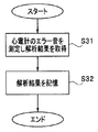
- FIG. 10 is a flowchart illustrating an example of learning mode processing of the high-frequency output device 12 and the ultrasonic output device 15 according to this modification.
- the learning mode of the high-frequency output device 12 will be described.
- the processing in the learning mode of the ultrasonic output device 15 is the same, and the description thereof will be omitted.
- the high-frequency output device 12 When the user performs a predetermined operation on the touch panel 20, the high-frequency output device 12 enters the learning mode.
- the user operates an electrocardiograph (not shown) to set an error sound and causes the high-frequency output device 12 to execute the learning mode process.
- the CPU 28 causes the sound analysis unit 102 to analyze the audio signal output from the microphone 101, and acquires analysis result information including sound feature data and volume data (S31).
- the CPU 28 stores the information of the analysis result in the flash memory 36 (S32).
- the high-frequency output device 12 obtains, that is, learns, an error sound of an electrocardiograph that is another medical device that cannot communicate, and stores sound information about the error sound in the flash memory 36 that is a storage device.
- the high-frequency output device 12 adjusts the output volume level generated by itself based on the electrocardiograph error sound stored in the learning mode.
- FIG. 11 is a flowchart illustrating an example of processing when an electrocardiograph error sound is generated in the high-frequency output device 12.
- the processing when the electrocardiograph error sound is generated in the high-frequency output device 12 will be described.
- the processing when the electrocardiograph error sound is generated in the ultrasonic output device 15 is the same, and the description thereof will be omitted. .
- the CPU 28 determines whether or not an electrocardiograph error sound has occurred based on the analysis result information from the sound analysis unit 102 (S41). This determination is performed by comparing the analysis result information from the sound analysis unit 102 input in real time with the electrocardiograph error sound information stored in the flash memory 36. When the input analysis result information from the sound analysis unit 102 matches the electrocardiograph error sound information stored in the flash memory 36, it is determined that an electrocardiograph error sound has occurred.
- each CPU that is a sound output control unit detects a predetermined sound output from an electrocardiograph as the third medical device, the output volume of the sound output from the speaker of its own medical device Is lower than the output volume of the sound output from the electrocardiograph.
- the high-frequency output device 12 and the ultrasonic output device 15 cooperate with each other in output volume level through communication, and other than the high-frequency output device 12 and the ultrasonic output device 15. Cooperation with the sound generated in the medical device can also be taken.
Landscapes
- Health & Medical Sciences (AREA)
- Life Sciences & Earth Sciences (AREA)
- Surgery (AREA)
- Engineering & Computer Science (AREA)
- Animal Behavior & Ethology (AREA)
- Molecular Biology (AREA)
- Veterinary Medicine (AREA)
- Public Health (AREA)
- Biomedical Technology (AREA)
- Heart & Thoracic Surgery (AREA)
- Medical Informatics (AREA)
- General Health & Medical Sciences (AREA)
- Physics & Mathematics (AREA)
- Otolaryngology (AREA)
- Nuclear Medicine, Radiotherapy & Molecular Imaging (AREA)
- Plasma & Fusion (AREA)
- Biophysics (AREA)
- Pathology (AREA)
- Surgical Instruments (AREA)
Abstract
La présente invention concerne un dispositif de sortie d'ondes à haute fréquence (12) et un dispositif de sortie d'ultrasons (15), qui sont des dispositifs médicaux, ayant respectivement une unité centrale (28, 42), un circuit de communication (31, 49), et un haut-parleur (18, 19). Lorsque le niveau du volume de sortie du son provenant du haut-parleur d'une unité centrale associée a été modifié, l'unité centrale associée transmet les informations sur le niveau de volume de sortie modifiées depuis le circuit de communication vers un autre dispositif médical, et régule le volume de sortie du son provenant du haut-parleur associé sur la base des informations de volume de sortie du son provenant du haut-parleur de l'autre dispositif reçues par le circuit de communication.
Priority Applications (4)
| Application Number | Priority Date | Filing Date | Title |
|---|---|---|---|
| CN201280048224.9A CN103841910B (zh) | 2012-01-19 | 2012-10-29 | 医疗系统 |
| JP2013530442A JP5465360B2 (ja) | 2012-01-19 | 2012-10-29 | 医療システム |
| EP12865932.3A EP2740430B1 (fr) | 2012-01-19 | 2012-10-29 | Système médical |
| US13/938,737 US8986288B2 (en) | 2012-01-19 | 2013-07-10 | Medical system |
Applications Claiming Priority (2)
| Application Number | Priority Date | Filing Date | Title |
|---|---|---|---|
| US201261588353P | 2012-01-19 | 2012-01-19 | |
| US61/588353 | 2012-01-19 |
Related Child Applications (1)
| Application Number | Title | Priority Date | Filing Date |
|---|---|---|---|
| US13/938,737 Continuation US8986288B2 (en) | 2012-01-19 | 2013-07-10 | Medical system |
Publications (1)
| Publication Number | Publication Date |
|---|---|
| WO2013108461A1 true WO2013108461A1 (fr) | 2013-07-25 |
Family
ID=48798898
Family Applications (1)
| Application Number | Title | Priority Date | Filing Date |
|---|---|---|---|
| PCT/JP2012/077842 Ceased WO2013108461A1 (fr) | 2012-01-19 | 2012-10-29 | Système médical |
Country Status (5)
| Country | Link |
|---|---|
| US (1) | US8986288B2 (fr) |
| EP (1) | EP2740430B1 (fr) |
| JP (1) | JP5465360B2 (fr) |
| CN (1) | CN103841910B (fr) |
| WO (1) | WO2013108461A1 (fr) |
Cited By (1)
| Publication number | Priority date | Publication date | Assignee | Title |
|---|---|---|---|---|
| JP2022527937A (ja) * | 2019-03-29 | 2022-06-07 | シラグ・ゲーエムベーハー・インターナショナル | モジュール式エネルギーシステムのエネルギーモジュール用のオーディオトーン構造 |
Families Citing this family (136)
| Publication number | Priority date | Publication date | Assignee | Title |
|---|---|---|---|---|
| US11871901B2 (en) | 2012-05-20 | 2024-01-16 | Cilag Gmbh International | Method for situational awareness for surgical network or surgical network connected device capable of adjusting function based on a sensed situation or usage |
| USD753145S1 (en) * | 2013-12-30 | 2016-04-05 | Samsung Electronics Co., Ltd. | Display screen or portion thereof with icon |
| US11504192B2 (en) | 2014-10-30 | 2022-11-22 | Cilag Gmbh International | Method of hub communication with surgical instrument systems |
| US11141160B2 (en) | 2017-10-30 | 2021-10-12 | Cilag Gmbh International | Clip applier comprising a motor controller |
| US11311342B2 (en) | 2017-10-30 | 2022-04-26 | Cilag Gmbh International | Method for communicating with surgical instrument systems |
| US11291510B2 (en) | 2017-10-30 | 2022-04-05 | Cilag Gmbh International | Method of hub communication with surgical instrument systems |
| US11510741B2 (en) | 2017-10-30 | 2022-11-29 | Cilag Gmbh International | Method for producing a surgical instrument comprising a smart electrical system |
| US11051836B2 (en) | 2017-10-30 | 2021-07-06 | Cilag Gmbh International | Surgical clip applier comprising an empty clip cartridge lockout |
| US11564756B2 (en) | 2017-10-30 | 2023-01-31 | Cilag Gmbh International | Method of hub communication with surgical instrument systems |
| US11801098B2 (en) | 2017-10-30 | 2023-10-31 | Cilag Gmbh International | Method of hub communication with surgical instrument systems |
| US11911045B2 (en) | 2017-10-30 | 2024-02-27 | Cllag GmbH International | Method for operating a powered articulating multi-clip applier |
| US11317919B2 (en) | 2017-10-30 | 2022-05-03 | Cilag Gmbh International | Clip applier comprising a clip crimping system |
| US11998193B2 (en) | 2017-12-28 | 2024-06-04 | Cilag Gmbh International | Method for usage of the shroud as an aspect of sensing or controlling a powered surgical device, and a control algorithm to adjust its default operation |
| US11304745B2 (en) | 2017-12-28 | 2022-04-19 | Cilag Gmbh International | Surgical evacuation sensing and display |
| US11284936B2 (en) | 2017-12-28 | 2022-03-29 | Cilag Gmbh International | Surgical instrument having a flexible electrode |
| US11540855B2 (en) | 2017-12-28 | 2023-01-03 | Cilag Gmbh International | Controlling activation of an ultrasonic surgical instrument according to the presence of tissue |
| US11602393B2 (en) | 2017-12-28 | 2023-03-14 | Cilag Gmbh International | Surgical evacuation sensing and generator control |
| US11832899B2 (en) | 2017-12-28 | 2023-12-05 | Cilag Gmbh International | Surgical systems with autonomously adjustable control programs |
| US11324557B2 (en) | 2017-12-28 | 2022-05-10 | Cilag Gmbh International | Surgical instrument with a sensing array |
| US11576677B2 (en) | 2017-12-28 | 2023-02-14 | Cilag Gmbh International | Method of hub communication, processing, display, and cloud analytics |
| US11612444B2 (en) | 2017-12-28 | 2023-03-28 | Cilag Gmbh International | Adjustment of a surgical device function based on situational awareness |
| US11896443B2 (en) | 2017-12-28 | 2024-02-13 | Cilag Gmbh International | Control of a surgical system through a surgical barrier |
| US11109866B2 (en) | 2017-12-28 | 2021-09-07 | Cilag Gmbh International | Method for circular stapler control algorithm adjustment based on situational awareness |
| US11589888B2 (en) | 2017-12-28 | 2023-02-28 | Cilag Gmbh International | Method for controlling smart energy devices |
| US11410259B2 (en) | 2017-12-28 | 2022-08-09 | Cilag Gmbh International | Adaptive control program updates for surgical devices |
| US11857152B2 (en) | 2017-12-28 | 2024-01-02 | Cilag Gmbh International | Surgical hub spatial awareness to determine devices in operating theater |
| US11076921B2 (en) | 2017-12-28 | 2021-08-03 | Cilag Gmbh International | Adaptive control program updates for surgical hubs |
| US11672605B2 (en) | 2017-12-28 | 2023-06-13 | Cilag Gmbh International | Sterile field interactive control displays |
| US12396806B2 (en) | 2017-12-28 | 2025-08-26 | Cilag Gmbh International | Adjustment of a surgical device function based on situational awareness |
| US11571234B2 (en) | 2017-12-28 | 2023-02-07 | Cilag Gmbh International | Temperature control of ultrasonic end effector and control system therefor |
| US11424027B2 (en) | 2017-12-28 | 2022-08-23 | Cilag Gmbh International | Method for operating surgical instrument systems |
| US11132462B2 (en) | 2017-12-28 | 2021-09-28 | Cilag Gmbh International | Data stripping method to interrogate patient records and create anonymized record |
| US11147607B2 (en) | 2017-12-28 | 2021-10-19 | Cilag Gmbh International | Bipolar combination device that automatically adjusts pressure based on energy modality |
| US11464559B2 (en) | 2017-12-28 | 2022-10-11 | Cilag Gmbh International | Estimating state of ultrasonic end effector and control system therefor |
| US11864728B2 (en) | 2017-12-28 | 2024-01-09 | Cilag Gmbh International | Characterization of tissue irregularities through the use of mono-chromatic light refractivity |
| US11896322B2 (en) | 2017-12-28 | 2024-02-13 | Cilag Gmbh International | Sensing the patient position and contact utilizing the mono-polar return pad electrode to provide situational awareness to the hub |
| US11832840B2 (en) | 2017-12-28 | 2023-12-05 | Cilag Gmbh International | Surgical instrument having a flexible circuit |
| US20190201112A1 (en) | 2017-12-28 | 2019-07-04 | Ethicon Llc | Computer implemented interactive surgical systems |
| US11678881B2 (en) | 2017-12-28 | 2023-06-20 | Cilag Gmbh International | Spatial awareness of surgical hubs in operating rooms |
| US11432885B2 (en) | 2017-12-28 | 2022-09-06 | Cilag Gmbh International | Sensing arrangements for robot-assisted surgical platforms |
| US11969216B2 (en) | 2017-12-28 | 2024-04-30 | Cilag Gmbh International | Surgical network recommendations from real time analysis of procedure variables against a baseline highlighting differences from the optimal solution |
| JP2021509061A (ja) | 2017-12-28 | 2021-03-18 | エシコン エルエルシーEthicon LLC | 状況認識に基づく外科用デバイスの機能の調節 |
| US11419667B2 (en) | 2017-12-28 | 2022-08-23 | Cilag Gmbh International | Ultrasonic energy device which varies pressure applied by clamp arm to provide threshold control pressure at a cut progression location |
| US11179175B2 (en) | 2017-12-28 | 2021-11-23 | Cilag Gmbh International | Controlling an ultrasonic surgical instrument according to tissue location |
| US11529187B2 (en) | 2017-12-28 | 2022-12-20 | Cilag Gmbh International | Surgical evacuation sensor arrangements |
| US11202570B2 (en) | 2017-12-28 | 2021-12-21 | Cilag Gmbh International | Communication hub and storage device for storing parameters and status of a surgical device to be shared with cloud based analytics systems |
| US12376855B2 (en) | 2017-12-28 | 2025-08-05 | Cilag Gmbh International | Safety systems for smart powered surgical stapling |
| US11559308B2 (en) | 2017-12-28 | 2023-01-24 | Cilag Gmbh International | Method for smart energy device infrastructure |
| US11389164B2 (en) | 2017-12-28 | 2022-07-19 | Cilag Gmbh International | Method of using reinforced flexible circuits with multiple sensors to optimize performance of radio frequency devices |
| US11744604B2 (en) | 2017-12-28 | 2023-09-05 | Cilag Gmbh International | Surgical instrument with a hardware-only control circuit |
| US11818052B2 (en) | 2017-12-28 | 2023-11-14 | Cilag Gmbh International | Surgical network determination of prioritization of communication, interaction, or processing based on system or device needs |
| US11969142B2 (en) | 2017-12-28 | 2024-04-30 | Cilag Gmbh International | Method of compressing tissue within a stapling device and simultaneously displaying the location of the tissue within the jaws |
| US11559307B2 (en) | 2017-12-28 | 2023-01-24 | Cilag Gmbh International | Method of robotic hub communication, detection, and control |
| US11937769B2 (en) | 2017-12-28 | 2024-03-26 | Cilag Gmbh International | Method of hub communication, processing, storage and display |
| US11278281B2 (en) | 2017-12-28 | 2022-03-22 | Cilag Gmbh International | Interactive surgical system |
| US12096916B2 (en) | 2017-12-28 | 2024-09-24 | Cilag Gmbh International | Method of sensing particulate from smoke evacuated from a patient, adjusting the pump speed based on the sensed information, and communicating the functional parameters of the system to the hub |
| US10595887B2 (en) | 2017-12-28 | 2020-03-24 | Ethicon Llc | Systems for adjusting end effector parameters based on perioperative information |
| US11304699B2 (en) | 2017-12-28 | 2022-04-19 | Cilag Gmbh International | Method for adaptive control schemes for surgical network control and interaction |
| US11308075B2 (en) | 2017-12-28 | 2022-04-19 | Cilag Gmbh International | Surgical network, instrument, and cloud responses based on validation of received dataset and authentication of its source and integrity |
| US10758310B2 (en) | 2017-12-28 | 2020-09-01 | Ethicon Llc | Wireless pairing of a surgical device with another device within a sterile surgical field based on the usage and situational awareness of devices |
| US11633237B2 (en) | 2017-12-28 | 2023-04-25 | Cilag Gmbh International | Usage and technique analysis of surgeon / staff performance against a baseline to optimize device utilization and performance for both current and future procedures |
| US11311306B2 (en) | 2017-12-28 | 2022-04-26 | Cilag Gmbh International | Surgical systems for detecting end effector tissue distribution irregularities |
| US11213359B2 (en) | 2017-12-28 | 2022-01-04 | Cilag Gmbh International | Controllers for robot-assisted surgical platforms |
| WO2019133144A1 (fr) | 2017-12-28 | 2019-07-04 | Ethicon Llc | Détection et intensification des réponses de sécurité d'instruments chirurgicaux à des menaces à la gravité croissante |
| US11234756B2 (en) | 2017-12-28 | 2022-02-01 | Cilag Gmbh International | Powered surgical tool with predefined adjustable control algorithm for controlling end effector parameter |
| US11317937B2 (en) | 2018-03-08 | 2022-05-03 | Cilag Gmbh International | Determining the state of an ultrasonic end effector |
| US11257589B2 (en) | 2017-12-28 | 2022-02-22 | Cilag Gmbh International | Real-time analysis of comprehensive cost of all instrumentation used in surgery utilizing data fluidity to track instruments through stocking and in-house processes |
| US11304720B2 (en) | 2017-12-28 | 2022-04-19 | Cilag Gmbh International | Activation of energy devices |
| US11364075B2 (en) | 2017-12-28 | 2022-06-21 | Cilag Gmbh International | Radio frequency energy device for delivering combined electrical signals |
| US11253315B2 (en) | 2017-12-28 | 2022-02-22 | Cilag Gmbh International | Increasing radio frequency to create pad-less monopolar loop |
| US11786245B2 (en) | 2017-12-28 | 2023-10-17 | Cilag Gmbh International | Surgical systems with prioritized data transmission capabilities |
| US11446052B2 (en) | 2017-12-28 | 2022-09-20 | Cilag Gmbh International | Variation of radio frequency and ultrasonic power level in cooperation with varying clamp arm pressure to achieve predefined heat flux or power applied to tissue |
| US11771487B2 (en) | 2017-12-28 | 2023-10-03 | Cilag Gmbh International | Mechanisms for controlling different electromechanical systems of an electrosurgical instrument |
| US12062442B2 (en) | 2017-12-28 | 2024-08-13 | Cilag Gmbh International | Method for operating surgical instrument systems |
| US11786251B2 (en) | 2017-12-28 | 2023-10-17 | Cilag Gmbh International | Method for adaptive control schemes for surgical network control and interaction |
| US11423007B2 (en) | 2017-12-28 | 2022-08-23 | Cilag Gmbh International | Adjustment of device control programs based on stratified contextual data in addition to the data |
| US11464535B2 (en) | 2017-12-28 | 2022-10-11 | Cilag Gmbh International | Detection of end effector emersion in liquid |
| US11419630B2 (en) | 2017-12-28 | 2022-08-23 | Cilag Gmbh International | Surgical system distributed processing |
| US11376002B2 (en) | 2017-12-28 | 2022-07-05 | Cilag Gmbh International | Surgical instrument cartridge sensor assemblies |
| US12127729B2 (en) | 2017-12-28 | 2024-10-29 | Cilag Gmbh International | Method for smoke evacuation for surgical hub |
| US20190201090A1 (en) | 2017-12-28 | 2019-07-04 | Ethicon Llc | Capacitive coupled return path pad with separable array elements |
| US10918310B2 (en) | 2018-01-03 | 2021-02-16 | Biosense Webster (Israel) Ltd. | Fast anatomical mapping (FAM) using volume filling |
| US10892995B2 (en) | 2017-12-28 | 2021-01-12 | Ethicon Llc | Surgical network determination of prioritization of communication, interaction, or processing based on system or device needs |
| US11304763B2 (en) | 2017-12-28 | 2022-04-19 | Cilag Gmbh International | Image capturing of the areas outside the abdomen to improve placement and control of a surgical device in use |
| US11166772B2 (en) | 2017-12-28 | 2021-11-09 | Cilag Gmbh International | Surgical hub coordination of control and communication of operating room devices |
| US11266468B2 (en) | 2017-12-28 | 2022-03-08 | Cilag Gmbh International | Cooperative utilization of data derived from secondary sources by intelligent surgical hubs |
| US20190201113A1 (en) | 2017-12-28 | 2019-07-04 | Ethicon Llc | Controls for robot-assisted surgical platforms |
| US11291495B2 (en) | 2017-12-28 | 2022-04-05 | Cilag Gmbh International | Interruption of energy due to inadvertent capacitive coupling |
| US11903601B2 (en) | 2017-12-28 | 2024-02-20 | Cilag Gmbh International | Surgical instrument comprising a plurality of drive systems |
| US11666331B2 (en) | 2017-12-28 | 2023-06-06 | Cilag Gmbh International | Systems for detecting proximity of surgical end effector to cancerous tissue |
| US20190206569A1 (en) | 2017-12-28 | 2019-07-04 | Ethicon Llc | Method of cloud based data analytics for use with the hub |
| US11659023B2 (en) | 2017-12-28 | 2023-05-23 | Cilag Gmbh International | Method of hub communication |
| US12458351B2 (en) | 2017-12-28 | 2025-11-04 | Cilag Gmbh International | Variable output cartridge sensor assembly |
| US11259830B2 (en) | 2018-03-08 | 2022-03-01 | Cilag Gmbh International | Methods for controlling temperature in ultrasonic device |
| US11399858B2 (en) | 2018-03-08 | 2022-08-02 | Cilag Gmbh International | Application of smart blade technology |
| US11986233B2 (en) | 2018-03-08 | 2024-05-21 | Cilag Gmbh International | Adjustment of complex impedance to compensate for lost power in an articulating ultrasonic device |
| US12303159B2 (en) | 2018-03-08 | 2025-05-20 | Cilag Gmbh International | Methods for estimating and controlling state of ultrasonic end effector |
| US11471156B2 (en) | 2018-03-28 | 2022-10-18 | Cilag Gmbh International | Surgical stapling devices with improved rotary driven closure systems |
| US11090047B2 (en) | 2018-03-28 | 2021-08-17 | Cilag Gmbh International | Surgical instrument comprising an adaptive control system |
| US11278280B2 (en) | 2018-03-28 | 2022-03-22 | Cilag Gmbh International | Surgical instrument comprising a jaw closure lockout |
| US11129611B2 (en) | 2018-03-28 | 2021-09-28 | Cilag Gmbh International | Surgical staplers with arrangements for maintaining a firing member thereof in a locked configuration unless a compatible cartridge has been installed therein |
| US11259806B2 (en) | 2018-03-28 | 2022-03-01 | Cilag Gmbh International | Surgical stapling devices with features for blocking advancement of a camming assembly of an incompatible cartridge installed therein |
| JP2019188723A (ja) * | 2018-04-26 | 2019-10-31 | 京セラドキュメントソリューションズ株式会社 | 画像処理装置、動作制御方法 |
| US11804679B2 (en) | 2018-09-07 | 2023-10-31 | Cilag Gmbh International | Flexible hand-switch circuit |
| US12144136B2 (en) | 2018-09-07 | 2024-11-12 | Cilag Gmbh International | Modular surgical energy system with module positional awareness with digital logic |
| US11923084B2 (en) | 2018-09-07 | 2024-03-05 | Cilag Gmbh International | First and second communication protocol arrangement for driving primary and secondary devices through a single port |
| US11471206B2 (en) * | 2018-09-07 | 2022-10-18 | Cilag Gmbh International | Method for controlling a modular energy system user interface |
| US12035956B2 (en) | 2018-09-07 | 2024-07-16 | Cilag Gmbh International | Instrument tracking arrangement based on real time clock information |
| US11298130B2 (en) | 2019-02-19 | 2022-04-12 | Cilag Gmbh International | Staple cartridge retainer with frangible authentication key |
| US11464511B2 (en) | 2019-02-19 | 2022-10-11 | Cilag Gmbh International | Surgical staple cartridges with movable authentication key arrangements |
| US11357503B2 (en) | 2019-02-19 | 2022-06-14 | Cilag Gmbh International | Staple cartridge retainers with frangible retention features and methods of using same |
| US11369377B2 (en) | 2019-02-19 | 2022-06-28 | Cilag Gmbh International | Surgical stapling assembly with cartridge based retainer configured to unlock a firing lockout |
| US11317915B2 (en) | 2019-02-19 | 2022-05-03 | Cilag Gmbh International | Universal cartridge based key feature that unlocks multiple lockout arrangements in different surgical staplers |
| USD964564S1 (en) | 2019-06-25 | 2022-09-20 | Cilag Gmbh International | Surgical staple cartridge retainer with a closure system authentication key |
| USD950728S1 (en) | 2019-06-25 | 2022-05-03 | Cilag Gmbh International | Surgical staple cartridge |
| USD952144S1 (en) | 2019-06-25 | 2022-05-17 | Cilag Gmbh International | Surgical staple cartridge retainer with firing system authentication key |
| USD939545S1 (en) | 2019-09-05 | 2021-12-28 | Cilag Gmbh International | Display panel or portion thereof with graphical user interface for energy module |
| USD928726S1 (en) | 2019-09-05 | 2021-08-24 | Cilag Gmbh International | Energy module monopolar port |
| USD924139S1 (en) | 2019-09-05 | 2021-07-06 | Ethicon Llc | Energy module with a backplane connector |
| USD928725S1 (en) | 2019-09-05 | 2021-08-24 | Cilag Gmbh International | Energy module |
| US12040749B2 (en) | 2021-03-30 | 2024-07-16 | Cilag Gmbh International | Modular energy system with dual amplifiers and techniques for updating parameters thereof |
| US11857252B2 (en) | 2021-03-30 | 2024-01-02 | Cilag Gmbh International | Bezel with light blocking features for modular energy system |
| US12369994B2 (en) | 2021-03-30 | 2025-07-29 | Cilag Gmbh International | Modular energy system with multi-energy port splitter for multiple energy devices |
| US12142373B2 (en) | 2021-03-30 | 2024-11-12 | Cilag Gmbh International | Modular energy system with hardware mitigated communication |
| US12329437B2 (en) | 2021-03-30 | 2025-06-17 | Cilag Gmbh International | Surgical proceduralization via modular energy system |
| US12004824B2 (en) | 2021-03-30 | 2024-06-11 | Cilag Gmbh International | Architecture for modular energy system |
| US12127777B2 (en) | 2021-03-30 | 2024-10-29 | Cilag Gmbh International | Energy delivery mitigations for modular energy systems |
| US11978554B2 (en) | 2021-03-30 | 2024-05-07 | Cilag Gmbh International | Radio frequency identification token for wireless surgical instruments |
| US11980411B2 (en) | 2021-03-30 | 2024-05-14 | Cilag Gmbh International | Header for modular energy system |
| US11968776B2 (en) | 2021-03-30 | 2024-04-23 | Cilag Gmbh International | Method for mechanical packaging for modular energy system |
| US11963727B2 (en) | 2021-03-30 | 2024-04-23 | Cilag Gmbh International | Method for system architecture for modular energy system |
| US12228987B2 (en) | 2021-03-30 | 2025-02-18 | Cilag Gmbh International | Method for energy delivery for modular energy system |
| US11950860B2 (en) | 2021-03-30 | 2024-04-09 | Cilag Gmbh International | User interface mitigation techniques for modular energy systems |
| US12235697B2 (en) | 2021-03-30 | 2025-02-25 | Cilag Gmbh International | Backplane connector attachment mechanism for modular energy system |
| US12354186B2 (en) | 2021-04-14 | 2025-07-08 | Cilag Gmbh International | Customization of overlaid data and configuration |
| US12079460B2 (en) | 2022-06-28 | 2024-09-03 | Cilag Gmbh International | Profiles for modular energy system |
Citations (6)
| Publication number | Priority date | Publication date | Assignee | Title |
|---|---|---|---|---|
| US5318563A (en) | 1992-06-04 | 1994-06-07 | Valley Forge Scientific Corporation | Bipolar RF generator |
| US6402741B1 (en) | 1999-10-08 | 2002-06-11 | Sherwood Services Ag | Current and status monitor |
| JP2003199768A (ja) * | 2002-01-09 | 2003-07-15 | Olympus Optical Co Ltd | 医療システム |
| JP3111214U (ja) * | 2005-03-10 | 2005-07-14 | 株式会社オネストメディカル | 対極板付き電気メス |
| WO2006035659A1 (fr) * | 2004-09-27 | 2006-04-06 | Olympus Corporation | Systeme de fonctionnement ultrasonique |
| WO2011052390A1 (fr) * | 2009-10-28 | 2011-05-05 | オリンパスメディカルシステムズ株式会社 | Dispositif médical |
Family Cites Families (7)
| Publication number | Priority date | Publication date | Assignee | Title |
|---|---|---|---|---|
| US7473224B2 (en) * | 2001-05-29 | 2009-01-06 | Ethicon Endo-Surgery, Inc. | Deployable ultrasound medical transducers |
| JP4236436B2 (ja) * | 2002-09-19 | 2009-03-11 | オリンパス株式会社 | 内視鏡外科システム |
| JP3800626B2 (ja) * | 2003-01-30 | 2006-07-26 | ソニー株式会社 | 制御装置および方法、情報処理装置および方法、記録媒体、並びにプログラム |
| US9757142B2 (en) * | 2006-08-09 | 2017-09-12 | Olympus Corporation | Relay device and ultrasonic-surgical and electrosurgical system |
| US20080058803A1 (en) * | 2006-08-30 | 2008-03-06 | Kenichi Kimura | Surgical instrument and surgical instrument driving method |
| ES2442241T3 (es) * | 2008-03-31 | 2014-02-10 | Applied Medical Resources Corporation | Sistema electroquirúrgico con un mecanismo de conmutación |
| JP5607902B2 (ja) * | 2009-08-24 | 2014-10-15 | 日本光電工業株式会社 | 生体情報監視システム |
-
2012
- 2012-10-29 WO PCT/JP2012/077842 patent/WO2013108461A1/fr not_active Ceased
- 2012-10-29 EP EP12865932.3A patent/EP2740430B1/fr active Active
- 2012-10-29 JP JP2013530442A patent/JP5465360B2/ja not_active Expired - Fee Related
- 2012-10-29 CN CN201280048224.9A patent/CN103841910B/zh not_active Expired - Fee Related
-
2013
- 2013-07-10 US US13/938,737 patent/US8986288B2/en active Active
Patent Citations (7)
| Publication number | Priority date | Publication date | Assignee | Title |
|---|---|---|---|---|
| US5318563A (en) | 1992-06-04 | 1994-06-07 | Valley Forge Scientific Corporation | Bipolar RF generator |
| US6402741B1 (en) | 1999-10-08 | 2002-06-11 | Sherwood Services Ag | Current and status monitor |
| JP2003199768A (ja) * | 2002-01-09 | 2003-07-15 | Olympus Optical Co Ltd | 医療システム |
| WO2006035659A1 (fr) * | 2004-09-27 | 2006-04-06 | Olympus Corporation | Systeme de fonctionnement ultrasonique |
| US20080015473A1 (en) | 2004-09-27 | 2008-01-17 | Koh Shimizu | Ultrasonic Surgery System |
| JP3111214U (ja) * | 2005-03-10 | 2005-07-14 | 株式会社オネストメディカル | 対極板付き電気メス |
| WO2011052390A1 (fr) * | 2009-10-28 | 2011-05-05 | オリンパスメディカルシステムズ株式会社 | Dispositif médical |
Non-Patent Citations (1)
| Title |
|---|
| See also references of EP2740430A4 |
Cited By (2)
| Publication number | Priority date | Publication date | Assignee | Title |
|---|---|---|---|---|
| JP2022527937A (ja) * | 2019-03-29 | 2022-06-07 | シラグ・ゲーエムベーハー・インターナショナル | モジュール式エネルギーシステムのエネルギーモジュール用のオーディオトーン構造 |
| JP7451555B2 (ja) | 2019-03-29 | 2024-03-18 | シラグ・ゲーエムベーハー・インターナショナル | モジュール式エネルギーシステムのエネルギーモジュール用のオーディオトーン構造 |
Also Published As
| Publication number | Publication date |
|---|---|
| US20140031706A1 (en) | 2014-01-30 |
| EP2740430A1 (fr) | 2014-06-11 |
| JP5465360B2 (ja) | 2014-04-09 |
| US8986288B2 (en) | 2015-03-24 |
| EP2740430A4 (fr) | 2015-11-11 |
| CN103841910B (zh) | 2017-02-15 |
| EP2740430B1 (fr) | 2017-07-26 |
| JPWO2013108461A1 (ja) | 2015-05-11 |
| CN103841910A (zh) | 2014-06-04 |
Similar Documents
| Publication | Publication Date | Title |
|---|---|---|
| JP5465360B2 (ja) | 医療システム | |
| JP4997344B2 (ja) | 医療用デバイスの出力制御装置 | |
| JP4643510B2 (ja) | 手術システム制御装置及び手術機器のタイムアウト値設定方法 | |
| JP4755106B2 (ja) | 超音波手術システム | |
| JPWO2011052391A1 (ja) | 医療用装置 | |
| JP4465018B2 (ja) | 超音波診断装置 | |
| JP5214565B2 (ja) | 手術システム | |
| JP4813349B2 (ja) | 内視鏡システム | |
| JP2005058616A (ja) | 医療システム用制御装置及び医療システム用制御方法 | |
| JP2017018276A (ja) | 超音波画像生成システム | |
| JP5010778B2 (ja) | 内視鏡手術システム | |
| US8668685B2 (en) | Electric operation system | |
| JP2002336184A (ja) | 内視鏡システム | |
| JP4217216B2 (ja) | 電気手術システム | |
| JP2007319697A (ja) | 医療システム用制御装置 | |
| US20240398357A1 (en) | Medical device adjusting acoustic signal output volume and method of adjusting the acoustic signal output volume of a medical device | |
| JP2003339736A (ja) | 医療制御システム | |
| JP2004313341A (ja) | 医療機器システム | |
| JP2006288956A (ja) | 手術システム | |
| JP2006305155A (ja) | 制御装置 | |
| JP2003005777A (ja) | 手術システム制御装置 | |
| WO2026053344A1 (fr) | Système d'endoscope, procédé d'affichage d'image pour système d'endoscope, et processeur avec unité d'affichage | |
| JP2007175228A (ja) | 機器制御装置 | |
| JP2004223294A (ja) | 超音波手術システム | |
| JP2007319621A (ja) | 医療制御装置 |
Legal Events
| Date | Code | Title | Description |
|---|---|---|---|
| ENP | Entry into the national phase |
Ref document number: 2013530442 Country of ref document: JP Kind code of ref document: A |
|
| 121 | Ep: the epo has been informed by wipo that ep was designated in this application |
Ref document number: 12865932 Country of ref document: EP Kind code of ref document: A1 |
|
| REEP | Request for entry into the european phase |
Ref document number: 2012865932 Country of ref document: EP |
|
| NENP | Non-entry into the national phase |
Ref country code: DE |