WO2013108469A1 - Structure d'assemblage de verre pour fenêtre de portière et procédé d'assemblage de verre pour fenêtre de portière - Google Patents
Structure d'assemblage de verre pour fenêtre de portière et procédé d'assemblage de verre pour fenêtre de portière Download PDFInfo
- Publication number
- WO2013108469A1 WO2013108469A1 PCT/JP2012/079247 JP2012079247W WO2013108469A1 WO 2013108469 A1 WO2013108469 A1 WO 2013108469A1 JP 2012079247 W JP2012079247 W JP 2012079247W WO 2013108469 A1 WO2013108469 A1 WO 2013108469A1
- Authority
- WO
- WIPO (PCT)
- Prior art keywords
- door
- lower frame
- frame
- door glass
- glass
- Prior art date
- Legal status (The legal status is an assumption and is not a legal conclusion. Google has not performed a legal analysis and makes no representation as to the accuracy of the status listed.)
- Ceased
Links
Images






Classifications
-
- B—PERFORMING OPERATIONS; TRANSPORTING
- B60—VEHICLES IN GENERAL
- B60J—WINDOWS, WINDSCREENS, NON-FIXED ROOFS, DOORS, OR SIMILAR DEVICES FOR VEHICLES; REMOVABLE EXTERNAL PROTECTIVE COVERINGS SPECIALLY ADAPTED FOR VEHICLES
- B60J1/00—Windows; Windscreens; Accessories therefor
- B60J1/08—Windows; Windscreens; Accessories therefor arranged at vehicle sides
- B60J1/12—Windows; Windscreens; Accessories therefor arranged at vehicle sides adjustable
- B60J1/16—Windows; Windscreens; Accessories therefor arranged at vehicle sides adjustable slidable
- B60J1/17—Windows; Windscreens; Accessories therefor arranged at vehicle sides adjustable slidable vertically
-
- B—PERFORMING OPERATIONS; TRANSPORTING
- B60—VEHICLES IN GENERAL
- B60J—WINDOWS, WINDSCREENS, NON-FIXED ROOFS, DOORS, OR SIMILAR DEVICES FOR VEHICLES; REMOVABLE EXTERNAL PROTECTIVE COVERINGS SPECIALLY ADAPTED FOR VEHICLES
- B60J5/00—Doors
- B60J5/04—Doors arranged at the vehicle sides
- B60J5/0401—Upper door structure
- B60J5/0402—Upper door structure window frame details, including sash guides and glass runs
Definitions
- the present invention relates to a structure for assembling a door glass to, for example, an automobile door.
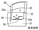
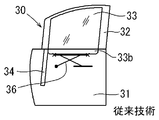
- the door panel 30 of the automobile has a door panel body 31 and a door glass 33 (see Japanese Patent Laid-Open Nos. 2005-336892 and 9-290634).
- the door panel body 31 is configured by combining an outer panel and an inner panel.
- a door frame 32 is coupled to the upper portion of the door panel body 31.
- the door glass 33 moves up and down to open and close the inside of the door frame 32.
- the door frame 32 includes a front frame portion 32a, a rear frame portion 32b, and an upper frame portion 32c.
- the front frame portion 32 a extends upward from the front portion of the door panel main body 31.
- the rear frame portion 32 b extends upward from the rear portion of the door panel main body 31.
- the upper frame portion 32c connects the upper portions of the front frame portion 32a and the rear frame portion 32b.
- Front and rear lower frames 34 and 35 that support the door glass 33 to be movable up and down are provided inside the door panel body 31.
- the front frame portion 32a and the rear frame portion 32b are connected to the lower frames 34 and 35, respectively.
- the lower frames 34 and 35 and the door frame 32 have a U-shaped cross section for guiding the edge of the door glass 33.
- a glass run (not shown) for reducing a gap between the door glass 33 is attached to the entire circumference. Thereby, the edge part of the door glass 33 can be guided without the backlash.
- the distance between the front and rear lower frames 34 and 35 is about several millimeters larger than the front and rear width dimension L1 of the door glass 33. As a result, a slight clearance is generated between the lower frames 34 and 35 and the door glass 33.
- the door glass 33 cannot be inserted vertically between the front and rear lower frames 34, 35. Therefore, the door glass 33 is thrown into the glass doorway (between the outer panel and the inner panel) of the door panel body 31 while being inclined on a plane parallel to the surface.
- the front upper corner portion 33a and the rear lower corner portion 33b are inserted into the front and rear lower frames 34 and 35, respectively.
- the inclination of the door glass 33 is returned on a plane parallel to the surface thereof, and the front end edge thereof is supported along the lower frame 34 on the front side.
- the rear edge is supported along the lower frame 35 on the rear side.
- the front-rear dimension (the diagonal dimension L2 between the front upper corner part 33a and the rear lower corner part 33b) of the door glass 33 tilted on a plane parallel to the surface is the front-rear width. It is larger than the dimension L1. Further, there may be a case where the distance between the front and rear lower frames 34 and 35 is larger. In this case, the tilt cannot be returned on a plane parallel to the front and rear lower frames 34 and 35 with the front upper corner portion 33a and the rear lower corner portion 33b being inserted.
- the door glass 33 is tilted on a surface parallel to the surface and inserted into the door panel body 31. Thereafter, as shown in FIG. 9, the inclination of the door glass 33 is returned and a mechanism such as a window regulator is fastened to the lower end edge thereof. Thereafter, as shown in FIG. 10, the door glass 33 is raised to secure a working space in the door panel main body 31. Thereafter, as shown in FIG. 11, the rear lower frame 35 is attached along the rear edge of the door glass 33. However, even when the door glass 33 is raised, the retrofitting operation of the lower frame 35 is performed in a narrow space between the outer panel and the inner panel. Therefore, workability is extremely bad.
- the door glass assembly structure includes a door panel body, a door frame, a front lower frame, a rear lower frame, and a door glass.
- the door frame is attached to the upper part of the door panel body.
- the front lower frame is continuous with the front portion of the door frame inside the door panel body.
- the rear lower frame continues to the rear portion of the door frame inside the door panel body.
- the door glass is supported by a door frame, a front lower frame, and a rear lower frame so as to be movable up and down.
- the door glass assembly structure has a configuration in which at least one of the front lower frame and the rear lower frame can be moved away from the front path or the rear part of the door frame so as to be retracted outside the door glass assembly path.
- At least one lower frame of the front lower frame or the rear lower frame is provided so as to be able to approach and separate from the front portion or the rear portion of the door frame. At least the one lower frame is separated from the front or rear portion of the door frame and retracted out of the door glass assembly path. Attach the door glass to the door panel body. At least one of the lower frames is brought close to the front or rear to return to a normal assembly position where the door glass is supported.
- one or both of the front lower frame and the rear lower frame, which are attached in the door panel body in advance, can be temporarily retracted to the retracted position outside the door glass assembly path (temporary assembly). Attached state).
- temporary assembly temporary assembly
- the lower frame is returned from the retracted position to the regular assembled position.
- the lower frame is connected to the front portion or the rear portion of the door frame and supports the edge of the door glass so that the door frame can be opened and closed. Therefore, it is not necessary to assemble the lower frame into the door panel main body after the door glass is assembled to the door panel main body as in the prior art.
- door glass with a large diagonal dimension can be assembled quickly and easily in the door panel body. Therefore, it is possible to improve the efficiency of assembling the door glass and reduce the number of work steps. Further, even a door glass having a large diagonal dimension can be assembled efficiently, so that restrictions on the glass design are reduced and the degree of freedom is improved.
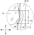
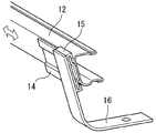
- FIG. 2 is an enlarged view of a portion II in FIG. 1 when a rear lower frame is in a retracted position. It is a perspective view of the slide support part of a rear lower frame.
- FIG. 4 is a sectional view taken along the line IV-IV in FIG. 1. It is a side view of the door panel for showing the door glass assembly
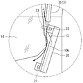
- FIG. 6 is an enlarged view of a portion VI in FIG. 5 when the rear lower frame is in a retracted position. It is a side view of the door panel of the state which attached the door glass.
- a front door 1 of an automobile includes a door panel body 2 and a door frame 3.
- the door panel body 2 has an outer panel and an inner panel that are coupled to each other.
- the door frame 3 extends upward from the upper part of the door panel body 2.
- a door glass 10 is supported inside the door frame 3 so as to be opened and closed vertically.
- the door frame 3 is substantially U-shaped and has a front frame portion (front portion) 3a, a rear frame portion (rear portion) 3b, and an upper frame portion 3c.
- the upper frame portion 3c joins the upper end portions of the front frame portion 3a and the rear frame portion 3b.
- the front frame portion 3a is fixed to the upper front portion of the door panel body 2 and extends upward from the upper front portion.
- the rear frame portion 3b is fixed to the upper rear portion of the door panel body 2 and extends upward from the upper rear portion.
- a front lower frame 11 and a rear lower frame 12 are mounted inside the door panel body 2 (between the outer panel and the inner panel).
- the front lower frame 11 continuously extends downward from the lower portion of the front frame portion 3a.
- the rear lower frame 12 continuously extends downward from the lower portion of the rear frame portion 3b.
- the door frame 3 and the front and rear lower frames 11 and 12 each have a U-shaped cross section that can receive the peripheral edge of the door glass 10.
- a glass run 13 is mounted along substantially the entire inner periphery of the door frame 3 and the lower frames 11 and 12.
- the front lower frame 11 is fixed to the door panel body 2 as shown in FIG.
- the rear lower frame 12 is provided on the door panel body 2 so as to be slidable up and down.
- a slide base 14 is attached to the rear surface of the rear lower frame 12 along the longitudinal direction of the rear lower frame 12.
- the slide base 14 is supported by the slide rail 15.
- the slide rail 15 is attached to the inner panel of the door panel body 2 by a bracket 16.
- the rear lower frame 12 is supported so as to be vertically slidable within a certain range along the slide rail 15.
- the rear lower frame 12 can slide along the slide rail 15 (see FIGS. 3 and 4) to the lower retracted position.
- the rear lower frame 12 can move away from the lower end portion of the rear frame portion 3b of the door frame 3 while forming a gap D by moving to the retracted position.
- the glass run 13 mounted between the rear frame portion 3b and the rear lower frame 12 remains in a substantially unchanged position even when the rear lower frame 12 is slid downward. Therefore, when the rear lower frame 12 is slid downward, the glass run 13 is exposed as illustrated.
- the door glass 10 is assembled while the rear lower frame 12 is slid to the retracted position.
- the door glass 10 is tilted on the surface parallel to the surface (counterclockwise in FIG. 1), and the front upper corner portion 10a is aligned with the front frame portion 3a of the door frame 3 or the front lower frame 11.
- the door glass 10 is put into the door panel main body 2 through the door entrance while keeping the rear lower corner portion 10b along the rear frame portion 3b. Thereafter, the inclination of the door glass 10 is returned, and the rear lower corner portion 10 b moves downward along the rear frame portion 3 b of the door frame 3.
- the rear lower corner portion 10b moves downward along a substantially arc locus (an assembly path J of the door glass 10) centered on the front upper corner portion 10a. Therefore, the rear lower corner portion 10b moves rearward and downward.
- a gap D is formed between the upper end portion of the rear lower frame 12 and the lower end portion of the rear frame portion 3b.
- the glass run 13 having flexibility (elasticity) exists in the gap D. Therefore, as shown in FIG. 2, the rear lower corner portion 10 b moves downward while pushing the glass run 13 backward to be elastically deformed, and does not interfere with the rear lower frame 12.
- the rear lower frame 12 When the door glass 10 is assembled to the door panel body 2 (loading operation), the rear lower frame 12 is moved to a retracted position outside the assembly path J of the door glass 10. Thereby, even when the diagonal dimension L2 is larger than the front-rear width dimension L1 of the door glass 10 (see FIG. 7), the door glass 10 can be easily assembled to the door panel body 2.
- the door glass 10 is tilted on a plane parallel to the surface to return to a normal angle.
- the door glass 10 is set in a posture capable of being fastened to the mechanism part of the window regulator. That is, the lower end edge of the door glass 10 is leveled (regular posture).
- the operator slides the rear lower frame 12 to the upper normal assembly position.
- the rear lower frame 12 is fixed to the regular assembly position, and the assembly of the rear lower frame 12 is completed. Therefore, the rear lower frame 12 can be assembled very quickly and easily as compared with the conventional retrofitting operation.
- the rear lower frame 12 is temporarily assembled before the door glass 10 is inserted, and is slid to the upper normal assembly position after the door glass 10 is inserted. Therefore, in this embodiment, the door glass 10 and the rear lower frame 12 are attached to the door panel body 2 extremely quickly and easily compared to the case where the rear lower frame is assembled to the door panel body 2 after the door glass is assembled to the door panel body as in the prior art. Can be assembled. Moreover, according to this form, the man-hour of the assembly
- the rear lower frame 20 is supported so as to be slidable in the longitudinal direction.
- a configuration is provided that allows the upper portion of the rear lower frame 20 to be retracted. Therefore, the rear lower frame 20 can be slid downward and retracted to a retracted position outside the assembly path of the door glass 10 (temporarily assembled state). After the door glass is assembled, the rear lower frame 20 can be slid upward, and the upper portion of the rear lower frame 20 can be returned to the normal assembly position that is substantially continuous with the door frame 3.
- the rear lower frame 12 may be slidable up and down (sliding type). Instead of this, the rear lower frame 12 may be rotated back and forth so that the rear lower frame 12 can move between a normal assembly position and a door glass retracting position (rotating type).
- FIGS. 5 and 6 The assembly structure according to another embodiment is shown in FIGS.
- the assembly structure of the embodiment shown in FIGS. 5 and 6 has a rear lower frame 20 that can be rotated forward and backward.
- the lower portion of the rear lower frame 20 is supported by a support shaft 21 so as to be tiltable back and forth.
- the rear lower frame 20 is supported by the inner panel of the door panel body 2 as in the embodiment of FIG.
- An engagement shaft 22 is provided on the upper portion of the rear lower frame 20.
- the engagement shaft 22 enters the guide hole 23.
- the guide hole 23 is provided in the inner panel of the door panel body 2.
- the guide hole 23 is formed along an arc centered on the support shaft 21.
- the engagement shaft 22 is movably inserted into the guide hole 23.
- the rear lower frame 20 is supported so as to tilt forward and backward within a range in which the engagement shaft 22 can move along the guide hole 23.
- FIG. 6 shows a state in which the rear lower frame 20 is tilted to the rearward retracted position.
- the rear lower frame 20 is located on the outside of the assembly path J of the door glass 10 on the movement locus of the rear lower corner portion 10 b of the door glass 10.
- the rear lower frame 20 tilts forward from the retracted position and can move to a proper assembly position where the upper end portion thereof is substantially continuous with the lower end portion of the rear frame portion 3 b of the door frame 3.
- Bolts are used for the support shaft 21 and the engagement shaft 22, respectively, and the rear lower frame 20 can be fixed at a regular assembly position by tightening the bolts.
- the door panel 10 is tilted upward (counterclockwise in the drawing) with respect to the normal position of the door glass 10 on a plane parallel to the door glass 10.
- the lower corner portion 10b can be returned downward without causing the rear lower frame 20 to interfere.
- the door glass 10 can be returned to a regular attitude
- the rear lower frame 20 is tilted forward and moved to the normal assembly position.
- the support shaft 21 and the engagement shaft 22 By tightening the support shaft 21 and the engagement shaft 22, the rear lower frame 20 can be fixed at a regular assembly position.
- the rear end edge of the door glass 10 is supported by the rear lower frame 20 and the glass run 13 fixed at a regular assembly position so as to be movable up and down.
- the rear lower frame 20 is rotatably supported on a plane parallel to the door glass 10.
- the upper part of the rear lower frame 20 is configured to be retractable. Accordingly, the rear lower frame 20 can be rotated to the retracted position and retracted outside the assembly path of the door glass 10 (temporarily assembled state). Therefore, if the rear lower frame 20 is rotated to the support position side after the door glass 10 is assembled to the door panel main body 2, the upper part thereof can return to the regular assembling position substantially continuous with the door frame 3.
- the rear lower frames 12 and 20 may be configured to be movable between a regular assembly position and a retracted position.
- the front lower frame 11 may be configured to be movable between a regular assembly position and a retracted position.
- 1 and 5 are applicable not only to automobile doors but also to other vehicle doors such as railways, ships, and aircraft.
Landscapes
- Engineering & Computer Science (AREA)
- Mechanical Engineering (AREA)
- Window Of Vehicle (AREA)
Applications Claiming Priority (2)
| Application Number | Priority Date | Filing Date | Title |
|---|---|---|---|
| JP2012008720A JP2013147130A (ja) | 2012-01-19 | 2012-01-19 | ドアガラスの組み付け構造 |
| JP2012-008720 | 2012-01-19 |
Publications (1)
| Publication Number | Publication Date |
|---|---|
| WO2013108469A1 true WO2013108469A1 (fr) | 2013-07-25 |
Family
ID=48798906
Family Applications (1)
| Application Number | Title | Priority Date | Filing Date |
|---|---|---|---|
| PCT/JP2012/079247 Ceased WO2013108469A1 (fr) | 2012-01-19 | 2012-11-12 | Structure d'assemblage de verre pour fenêtre de portière et procédé d'assemblage de verre pour fenêtre de portière |
Country Status (2)
| Country | Link |
|---|---|
| JP (1) | JP2013147130A (fr) |
| WO (1) | WO2013108469A1 (fr) |
Families Citing this family (1)
| Publication number | Priority date | Publication date | Assignee | Title |
|---|---|---|---|---|
| JP7754608B2 (ja) * | 2022-03-29 | 2025-10-15 | ダイハツ工業株式会社 | 車両用ドア |
Citations (3)
| Publication number | Priority date | Publication date | Assignee | Title |
|---|---|---|---|---|
| JPS60124718U (ja) * | 1984-01-30 | 1985-08-22 | 三菱自動車工業株式会社 | ドアサツシの取付構造 |
| JPH08150838A (ja) * | 1994-11-29 | 1996-06-11 | Suzuki Motor Corp | 自動車用ドア構造 |
| JP2004306885A (ja) * | 2003-04-10 | 2004-11-04 | Mitsubishi Motors Corp | ドアガラス艤装方法 |
-
2012
- 2012-01-19 JP JP2012008720A patent/JP2013147130A/ja active Pending
- 2012-11-12 WO PCT/JP2012/079247 patent/WO2013108469A1/fr not_active Ceased
Patent Citations (3)
| Publication number | Priority date | Publication date | Assignee | Title |
|---|---|---|---|---|
| JPS60124718U (ja) * | 1984-01-30 | 1985-08-22 | 三菱自動車工業株式会社 | ドアサツシの取付構造 |
| JPH08150838A (ja) * | 1994-11-29 | 1996-06-11 | Suzuki Motor Corp | 自動車用ドア構造 |
| JP2004306885A (ja) * | 2003-04-10 | 2004-11-04 | Mitsubishi Motors Corp | ドアガラス艤装方法 |
Also Published As
| Publication number | Publication date |
|---|---|
| JP2013147130A (ja) | 2013-08-01 |
Similar Documents
| Publication | Publication Date | Title |
|---|---|---|
| US12115914B2 (en) | Vehicle-bodywork part and wing-mirror arrangement for a vehicle-bodywork part | |
| US8225460B2 (en) | Multiple axis hinge for a vehicle body side door | |
| US7559597B2 (en) | Vehicle roof automatic opening/closing device | |
| JP6839106B2 (ja) | 車両ドア用フラッシュ窓ガラス装置、ドア、自動車、気密装置、及び対応する製造方法 | |
| JP5639618B2 (ja) | テールゲート付き車両 | |
| US11719030B2 (en) | Fastening arrangement for vehicle sliding door | |
| US6293602B1 (en) | Sliding tailgate panel | |
| WO2014006974A1 (fr) | Véhicule ayant un hayon | |
| US12188274B2 (en) | Door hinge device of vehicle | |
| US20090189412A1 (en) | Sliding door system | |
| JP2008062912A (ja) | サンルーフ装置におけるストッパ構造 | |
| CN119894700B (zh) | 车门组件 | |
| JP2013147130A (ja) | ドアガラスの組み付け構造 | |
| WO2014196257A1 (fr) | Véhicule | |
| US20250003274A1 (en) | Vehicle side portion structure | |
| JP3755603B2 (ja) | 車両用スライドドアの構造 | |
| US7121602B2 (en) | Shelf assembly for a vehicle | |
| JP6373808B2 (ja) | 車両用ドア | |
| WO2022249646A1 (fr) | Structure de déflecteur pour dispositif de toit ouvrant | |
| CN114450181A (zh) | 可伸缩遮阳板 | |
| JP5703085B2 (ja) | 車両用スライドドアの開閉装置 | |
| US12358572B2 (en) | Vehicle lower structure | |
| JP2742748B2 (ja) | 自動車のルーフ開閉装置 | |
| JP5594767B2 (ja) | 車両における荷室用デッキボード | |
| US10549612B2 (en) | Tilting sunroof structure |
Legal Events
| Date | Code | Title | Description |
|---|---|---|---|
| 121 | Ep: the epo has been informed by wipo that ep was designated in this application |
Ref document number: 12865609 Country of ref document: EP Kind code of ref document: A1 |
|
| NENP | Non-entry into the national phase |
Ref country code: DE |
|
| 122 | Ep: pct application non-entry in european phase |
Ref document number: 12865609 Country of ref document: EP Kind code of ref document: A1 |