WO2013108642A1 - Poudre de fer pour compact magnétique, compact magnétique, procédé de production d'une poudre de fer pour compact magnétique et procédé de production d'un compact magnétique - Google Patents
Poudre de fer pour compact magnétique, compact magnétique, procédé de production d'une poudre de fer pour compact magnétique et procédé de production d'un compact magnétique Download PDFInfo
- Publication number
- WO2013108642A1 WO2013108642A1 PCT/JP2013/050031 JP2013050031W WO2013108642A1 WO 2013108642 A1 WO2013108642 A1 WO 2013108642A1 JP 2013050031 W JP2013050031 W JP 2013050031W WO 2013108642 A1 WO2013108642 A1 WO 2013108642A1
- Authority
- WO
- WIPO (PCT)
- Prior art keywords
- powder
- less
- magnetic
- iron
- mass
- Prior art date
- Legal status (The legal status is an assumption and is not a legal conclusion. Google has not performed a legal analysis and makes no representation as to the accuracy of the status listed.)
- Ceased
Links
Images


Classifications
-
- H—ELECTRICITY
- H01—ELECTRIC ELEMENTS
- H01F—MAGNETS; INDUCTANCES; TRANSFORMERS; SELECTION OF MATERIALS FOR THEIR MAGNETIC PROPERTIES
- H01F1/00—Magnets or magnetic bodies characterised by the magnetic materials therefor; Selection of materials for their magnetic properties
- H01F1/01—Magnets or magnetic bodies characterised by the magnetic materials therefor; Selection of materials for their magnetic properties of inorganic materials
- H01F1/03—Magnets or magnetic bodies characterised by the magnetic materials therefor; Selection of materials for their magnetic properties of inorganic materials characterised by their coercivity
- H01F1/12—Magnets or magnetic bodies characterised by the magnetic materials therefor; Selection of materials for their magnetic properties of inorganic materials characterised by their coercivity of soft-magnetic materials
- H01F1/33—Magnets or magnetic bodies characterised by the magnetic materials therefor; Selection of materials for their magnetic properties of inorganic materials characterised by their coercivity of soft-magnetic materials mixtures of metallic and non-metallic particles; metallic particles having oxide skin
-
- B—PERFORMING OPERATIONS; TRANSPORTING
- B22—CASTING; POWDER METALLURGY
- B22F—WORKING METALLIC POWDER; MANUFACTURE OF ARTICLES FROM METALLIC POWDER; MAKING METALLIC POWDER; APPARATUS OR DEVICES SPECIALLY ADAPTED FOR METALLIC POWDER
- B22F1/00—Metallic powder; Treatment of metallic powder, e.g. to facilitate working or to improve properties
- B22F1/12—Metallic powder containing non-metallic particles
-
- B—PERFORMING OPERATIONS; TRANSPORTING
- B22—CASTING; POWDER METALLURGY
- B22F—WORKING METALLIC POWDER; MANUFACTURE OF ARTICLES FROM METALLIC POWDER; MAKING METALLIC POWDER; APPARATUS OR DEVICES SPECIALLY ADAPTED FOR METALLIC POWDER
- B22F9/00—Making metallic powder or suspensions thereof
- B22F9/02—Making metallic powder or suspensions thereof using physical processes
- B22F9/06—Making metallic powder or suspensions thereof using physical processes starting from liquid material
- B22F9/08—Making metallic powder or suspensions thereof using physical processes starting from liquid material by casting, e.g. through sieves or in water, by atomising or spraying
- B22F9/082—Making metallic powder or suspensions thereof using physical processes starting from liquid material by casting, e.g. through sieves or in water, by atomising or spraying atomising using a fluid
-
- C—CHEMISTRY; METALLURGY
- C22—METALLURGY; FERROUS OR NON-FERROUS ALLOYS; TREATMENT OF ALLOYS OR NON-FERROUS METALS
- C22C—ALLOYS
- C22C33/00—Making ferrous alloys
- C22C33/02—Making ferrous alloys by powder metallurgy
-
- C—CHEMISTRY; METALLURGY
- C22—METALLURGY; FERROUS OR NON-FERROUS ALLOYS; TREATMENT OF ALLOYS OR NON-FERROUS METALS
- C22C—ALLOYS
- C22C38/00—Ferrous alloys, e.g. steel alloys
- C22C38/002—Ferrous alloys, e.g. steel alloys containing In, Mg, or other elements not provided for in one single group C22C38/001 - C22C38/60
-
- C—CHEMISTRY; METALLURGY
- C22—METALLURGY; FERROUS OR NON-FERROUS ALLOYS; TREATMENT OF ALLOYS OR NON-FERROUS METALS
- C22C—ALLOYS
- C22C38/00—Ferrous alloys, e.g. steel alloys
- C22C38/02—Ferrous alloys, e.g. steel alloys containing silicon
-
- C—CHEMISTRY; METALLURGY
- C22—METALLURGY; FERROUS OR NON-FERROUS ALLOYS; TREATMENT OF ALLOYS OR NON-FERROUS METALS
- C22C—ALLOYS
- C22C38/00—Ferrous alloys, e.g. steel alloys
- C22C38/04—Ferrous alloys, e.g. steel alloys containing manganese
-
- C—CHEMISTRY; METALLURGY
- C22—METALLURGY; FERROUS OR NON-FERROUS ALLOYS; TREATMENT OF ALLOYS OR NON-FERROUS METALS
- C22C—ALLOYS
- C22C38/00—Ferrous alloys, e.g. steel alloys
- C22C38/12—Ferrous alloys, e.g. steel alloys containing tungsten, tantalum, molybdenum, vanadium, or niobium
-
- H—ELECTRICITY
- H01—ELECTRIC ELEMENTS
- H01F—MAGNETS; INDUCTANCES; TRANSFORMERS; SELECTION OF MATERIALS FOR THEIR MAGNETIC PROPERTIES
- H01F41/00—Apparatus or processes specially adapted for manufacturing or assembling magnets, inductances or transformers; Apparatus or processes specially adapted for manufacturing materials characterised by their magnetic properties
- H01F41/02—Apparatus or processes specially adapted for manufacturing or assembling magnets, inductances or transformers; Apparatus or processes specially adapted for manufacturing materials characterised by their magnetic properties for manufacturing cores, coils, or magnets
- H01F41/0206—Manufacturing of magnetic cores by mechanical means
- H01F41/0246—Manufacturing of magnetic circuits by moulding or by pressing powder
-
- B—PERFORMING OPERATIONS; TRANSPORTING
- B22—CASTING; POWDER METALLURGY
- B22F—WORKING METALLIC POWDER; MANUFACTURE OF ARTICLES FROM METALLIC POWDER; MAKING METALLIC POWDER; APPARATUS OR DEVICES SPECIALLY ADAPTED FOR METALLIC POWDER
- B22F9/00—Making metallic powder or suspensions thereof
- B22F9/02—Making metallic powder or suspensions thereof using physical processes
- B22F9/06—Making metallic powder or suspensions thereof using physical processes starting from liquid material
- B22F9/08—Making metallic powder or suspensions thereof using physical processes starting from liquid material by casting, e.g. through sieves or in water, by atomising or spraying
- B22F9/082—Making metallic powder or suspensions thereof using physical processes starting from liquid material by casting, e.g. through sieves or in water, by atomising or spraying atomising using a fluid
- B22F2009/0824—Making metallic powder or suspensions thereof using physical processes starting from liquid material by casting, e.g. through sieves or in water, by atomising or spraying atomising using a fluid with a specific atomising fluid
- B22F2009/0828—Making metallic powder or suspensions thereof using physical processes starting from liquid material by casting, e.g. through sieves or in water, by atomising or spraying atomising using a fluid with a specific atomising fluid with water
-
- Y—GENERAL TAGGING OF NEW TECHNOLOGICAL DEVELOPMENTS; GENERAL TAGGING OF CROSS-SECTIONAL TECHNOLOGIES SPANNING OVER SEVERAL SECTIONS OF THE IPC; TECHNICAL SUBJECTS COVERED BY FORMER USPC CROSS-REFERENCE ART COLLECTIONS [XRACs] AND DIGESTS
- Y02—TECHNOLOGIES OR APPLICATIONS FOR MITIGATION OR ADAPTATION AGAINST CLIMATE CHANGE
- Y02P—CLIMATE CHANGE MITIGATION TECHNOLOGIES IN THE PRODUCTION OR PROCESSING OF GOODS
- Y02P70/00—Climate change mitigation technologies in the production process for final industrial or consumer products
- Y02P70/50—Manufacturing or production processes characterised by the final manufactured product
Definitions
- the present invention relates to an iron powder produced by a water atomization method, and a dust magnetic body using the same.
- Powder compacts produced by die compression molding of soft magnetic powder such as iron powder (also referred to as “Fe powder”) are used in magnetic cores such as motors and reactors for power supply circuits.
- a dust core is generally easy to mold into a three-dimensional shape having isotropic magnetic characteristics and a high degree of freedom in shape. For this reason, when applied to a motor or the like, for example, compared to a laminated magnetic core made of silicon steel, it is expected to contribute to the reduction in size and weight of the magnetic core.
- a powder magnetic core using Fe (iron) powder hereinafter referred to as “water atomized Fe powder” that is mass-produced by a water atomizing manufacturing method is inexpensive, and the ductility of the Fe powder is low.
- development for practical application has been activated due to the advantage that the magnetic flux density increases due to the high density.
- the magnetic properties of the dust core In addition to high magnetic flux density, it is important for the magnetic properties of the dust core to have low energy loss when used under an alternating magnetic field called iron loss.
- the iron loss is mainly represented by the sum of eddy current loss and hysteresis loss.
- the hysteresis loss (or the coercive force proportional to the hysteresis loss) is a loss caused by the movement of the domain wall in the Fe powder that occurs in the magnetization process under an external magnetic field.
- Hysteresis loss is a defect in Fe powder that impedes domain wall movement, that is, pinning (lattice defects such as dislocations and grain boundaries, and chemical defects such as impurities other than Fe and precipitates composed of these) And the size of the Fe powder particles (the powder surface obstructs the domain wall motion) are strongly influenced.
- Water atomized Fe powder is very inexpensive and excellent in mass productivity as compared with gas atomized Fe powder using an inert gas, and is greatly different in terms of material structure and composition. That is, the material structure and composition of the Fe powder are very strongly affected by O.
- the Fe powder immediately after water atomization has an oxide formed by a reaction between molten iron and water, and a large amount of this oxide is formed on the surface.
- the C, N, and O gas impurity atoms and other constituent atoms in the Fe powder are frozen in the Fe crystal in a non-equilibrium state from a molten state in a pseudo-solid solution by quenching water.
- O introduced into Fe by reaction with water is contained in a large amount of several thousand wtppm in the form of oxides and solid solution atoms.
- the remaining of C and N in Fe is much less than O because they are removed because of the oxidizing atmosphere.
- Defects such as gas impurities and oxides in the Fe crystal after water atomization act as a pinning point for domain wall motion and deteriorate magnetic properties as described above.
- a hydrogen reduction heat treatment at a high temperature is the most effective as a subsequent material control process for the improvement.
- a large amount of O contained in the Fe powder decreases with the remaining C and N.
- the atoms in the Fe powder that were frozen in non-equilibrium during this high temperature hold form a new material structure by diffusion transfer under thermal equilibrium.
- the dominant structure in this new structure is an oxide which is dispersed and precipitated by the reaction between metal atoms in Fe and O which still remains.
- As the oxide not only an oxide of only Fe but also a complex oxide containing a metal that easily forms an oxide more than Fe is formed. Actually, at room temperature used as a dust core, O in Fe hardly dissolves and precipitates as a stable oxide.
- the hysteresis loss or coercive force which is the magnetic property of the powdered magnetic material of the actual reduced Fe powder, is obtained by pinning the domain wall in Fe to inhibit its movement, and C and N gas impurity atoms and oxides. Strongly affected. That is, the hysteresis loss or coercive force physically depends on the concentration of C and N, which is the number of pinning points of the domain wall, and the number density of oxide particles. Based on this microscopic magnetic property development mechanism and the above-mentioned poor solid solubility of O, especially O, which is the dominant factor of magnetism, is an entity in which O exists rather than paying attention to O concentration. Reducing the number density of oxides is an important technical issue for improving magnetic properties.
- Patent Document 1 no consideration is given to a method and technology for reducing the number density of oxide particles. It is believed that reducing the proportion of all oxides proposed here, ie, reducing the total amount of oxides, or reducing the O concentration alone, does not provide an essential solution for reducing coercivity. .
- the oxide studied in Patent Document 1 is a simple Fe oxide, many oxides are actually complex oxides containing impurity metal elements other than Fe described above. Furthermore, it is considered that it is difficult to effectively reduce O because the temperature is low at 800 ° C. for 3 hours, which is the hydrogen reduction heat treatment condition shown in the example of Patent Document 1. In addition, in a nitrogen atmosphere, which is a heat treatment condition for strain removal of a green compact, at 300 ° C. for 1 hour, the treatment temperature is low, primary recrystallization does not proceed, and the strain removal is considered insufficient.
- Patent Document 2 does not give consideration to a method and technology for reducing the number density of oxide particles.
- Patent Document 2 a composite Fe powder in which an existing Fe powder is further subjected to secondary treatment instead of Fe powder and an oxide containing Al (aluminum) or Si (silicone) is coated is studied. Therefore, it is considered that the structure of the Fe powder is not controlled.
- An object of the present invention is to provide a magnetic powder and a magnetic powder body that can improve magnetic properties.
- the iron powder for powder magnetic material according to the present invention has the following characteristics.
- the oxide particles include particles containing the metal element and oxygen as components.
- the number density of the average particle diameter of 2nm or more of the oxide particles, the average surface density in the cross section of the iron powder is 0.1 ⁇ 10 9 / cm 2 or more 4x10 9 / cm 2 or less.
- No. observed with STEM The schematic diagram of the material structure
- a feature of the present invention is an iron powder for magnetic powder, which efficiently reduces the amount of gas impurities O, C, and N introduced in the manufacturing process by high-temperature hydrogen reduction heat treatment, O having a higher residual concentration has a large influence on the magnetic properties, and is to reduce the number density of oxide particles, which are precipitates that govern the structure of the powder.
- the iron powder for a magnetic powder compact contains 99.7% by mass or more of Fe, 0.01 to 0.04% by mass of O as a gas impurity component, and 0.002% by mass of C. % Or less, and N is contained by 0.001 mass% or less. That is, all components other than Fe are 0.3 mass% or less including the impurity component inevitable on manufacture.
- the form of O contained in the iron powder is mainly oxide particles that are precipitated on the surface and the internal matrix and are composed of metal elements and O constituting the powder. It is an average particle diameter of the oxide particles is more than 2 nm, when determining the number density of the average surface density at any cross section of the powder, the number density of 0.1 ⁇ 10 9 / cm 2 or more 4x10 9 / cm 2 or less Have.
- the mass ratio of the iron powder having a particle diameter of 100 ⁇ m or more in the iron powder is 70% or more and less than 100%.
- the other aspect of the iron powder according to the present invention is characterized in that V (vanadium), Nb (niobium), and Ti (titanium) are included in all components other than Fe (0.3 mass% or less of the iron powder). At least one of them is contained in an amount of 0.0015 atomic% or more and 0.015 atomic% or less.
- the present invention is characterized in that in a method for producing iron powder for a dusting magnetic body, water atomized Fe powder which is cooled and atomized by spraying water on molten iron containing Fe as a main component is converted into H (hydrogen ) in a reducing atmosphere containing, diffusion coefficient and solubility is relatively large temperature range of O to O in Fe, i.e. at a temperature range of less than 880 ° C. or higher 911 ° C. just below the 911 ° C. is a 3 transformation point In other words, heat treatment is performed under conditions that are industrially and cost effective.
- This manufacturing method the number density of the oxide particles contained in the iron powder is adjusted to above 0.1 ⁇ 10 9 / cm 2 or more 4x10 9 / cm 2 or less.
- a feature of the method for producing a powder magnetic body according to the present invention includes a step of producing a so-called composite iron powder (composite soft magnetic powder) in which an insulating coating layer is provided on the iron powder, and after compacting the composite iron powder.
- composite iron powder composite soft magnetic powder
- primary recrystallization is allowed to proceed in a temperature range of 550 ° C. or higher and 600 ° C. or lower in air or nitrogen.
- the amount of V, Nb, or Ti which is an element that easily forms a thermodynamically stable oxide
- the density of the dispersed oxide is increased, and the moldability is increased. And further deteriorate the magnetic properties.
- a small amount within the range defined by the present invention a large amount of O is collected during the hydrogen reduction heat treatment, the composite oxide particles are grown greatly, and a plurality of oxides are aggregated and aggregated, thereby reducing the number density of the oxide particles. Can be reduced. That is, one oxide aggregate serves as one pinning point for the domain wall motion described above.
- the water atomized Fe powder contains a large amount of O produced by the reaction with water during atomization, and as a result, possesses a high-density oxide.
- the configuration of the present invention reduces the undesirable effects of oxides on powder hardness, compactability, and thermal recovery of molded body strain. This reduction technique solves the problem of reducing C and N at the same time, but the content of these elements in water atomized Fe powder is very small compared to O.
- iron powder for powdered magnetic material with reduced particle number density of oxides can be provided at low cost by controlled hydrogen reduction conditions and addition of a small amount of metal elements that can easily form more stable oxides.
- the deformation resistance of the water atomized Fe powder can be lowered to improve the moldability, and the primary recrystallization temperature can be lowered to increase the strain recovery efficiency.
- the coercive force and iron loss can be reduced by carrying out an effective heat treatment in the powder magnetic body made of the Fe powder according to the present invention coated with insulation.
- the present inventors reduced the deformation resistance of water-atomized Fe powder, lowered the primary recrystallization temperature, and further provided the coercive force brought about by the heat treatment carried out on the powder magnetic material produced from the water-atomized Fe powder coated with insulation.
- Water atomized Fe powder essentially contains a large amount of O produced by reaction with water during pulverization as a manufacturing problem.
- the solid solubility of O is, 70 wtppm in 20 ⁇ 30wtppm, 700 °C at 911 ° C. or higher is A 3 transformation point, 500 ° C. 10wtppm or less 2.5wtppm (Reference Document 1), or 951 ° C., 881 It is reported as 3.5 wtppm (reference document 2) at ° C. The measured values in these reports are different, but in any case, the solid solubility of O is very small.
- a heat treatment is performed for a set time, and an element having a strong affinity for O is added within an appropriate composition range, and during the hydrogen reduction heat treatment, a composite oxide containing the metal element and the additive element constituting the powder is formed.
- the main reduction reaction of O during the hydrogen reduction heat treatment is the reaction with H.
- the reduction efficiency of O that is, the reducing ability, is that O atoms in solid solution diffuse and move in the Fe powder and react with H on the surface to generate H 2 O and are removed.
- the value of the diffusion coefficient increases as the temperature increases, but differs depending on the crystal structure. That is, the diffusion coefficient of O in the Fe is hydrogen reduction temperature than ⁇ phase region ranging from 1000 ° C. or less over a 911 ° C. is A 3 transformation point, in the range of 880 ° C. or higher than 911 ° C. alpha-phase region Is larger (references 2, 3, 4), and therefore the ⁇ phase region is more efficient for reducing O. Further, in the temperature range of the ⁇ phase region, diffusion is more active, so that it is determined that the growth and coarsening of the oxide can be promoted and the number density of the oxide can be reduced.
- iron powder powdered by the water atomization method is contained in the powder by heat treatment in a reducing atmosphere containing hydrogen gas at a temperature range of 880 ° C. or higher and lower than 911 ° C. of the A 3 transformation point.
- a reducing atmosphere containing hydrogen gas at a temperature range of 880 ° C. or higher and lower than 911 ° C. of the A 3 transformation point.
- the above hydrogen reduction heat treatment is performed after water atomization to reduce the amount of gas impurities contained in the powder.
- it has a strong affinity with the above gas impurities, and by adding elements controlled to an appropriate composition range, the remaining O is agglomerated as an oxide, and a small amount of residual C and N are reduced. Aggregates as carbides and nitrides. In particular, the number density of the oxide particles can be effectively reduced by agglomeration and coarsening.
- At least one of V, Nb, and Ti is contained as an additive element. It is necessary to determine the addition amount within an appropriate range that can reduce the deformation resistance of the powder, the primary recrystallization temperature, and the coercive force and iron loss, which are the magnetic characteristics of the green compact.
- the iron powder (Fe powder) according to the present invention is produced by a water atomization method.
- the raw material iron is selected so that at least one of Cr (chromium), Mn (manganese), and Si inevitably mixed as impurities is included in the composition range described later.
- high pressure water is jetted together with the output from the lower nozzle of the crucible, rapidly solidified, and pulverized to recover Fe powder.
- the Fe powder for magnetic powder according to the present invention contains a large amount of O at a level of several thousand wtppm as described above immediately after the water atomization treatment.
- the surface of Fe powder is coated with many oxides, and oxides are also generated in the internal matrix, and many of the impurity atoms including O are rapidly solid-dissolved.
- the water atomized Fe powder according to the present invention is composed of a hydrogen impurity heat treatment after water atomization, and compositionally, O as a gas impurity component is 0.01 mass% or more and 0.04 mass% or less, and C is 0.002 mass% or less. , N is reduced to 0.001% by mass or less, and all components other than Fe including impurity components inevitable in production are set to 0.3% by mass or less. That is, the Fe powder according to the present invention contains 99.7% by mass or more of Fe.
- the number density of the oxide particles to be precipitated (average particle size oxide particles above 2 nm), when calculated as the average surface density at any cross section of the powder, 0.1 ⁇ 10 9 / cm 2 or more 4x10 9 / Cm 2 or less.
- the hydrogen reduction heat treatment temperature having a high ability of reducing and removing O in Fe powder is based on the A 3 transformation in consideration of the temperature range in which the diffusion coefficient value of O and the solid solubility are larger.
- the most effective range is 880 ° C. or more and less than 911 ° C. immediately below the point 911 ° C. (which is the ⁇ phase region). This is because the O permeability, that is, the O removal rate from the powder in a reducing atmosphere is proportional to the diffusion coefficient and the solid solubility. Even in the same ⁇ -phase region, the efficiency of O removal is further reduced at a low temperature of less than 880 ° C.
- the decrease in O leads to a decrease in the amount of oxide in the powder under thermal equilibrium.
- the number of particles increases when the size is small, and the number of particles decreases when the size is large.
- the number of oxide particles is the number of pinning points for dislocation and domain wall motion, a large oxide size is very advantageous for improving strength and magnetic properties.
- the ⁇ -phase region in the temperature range of the reduction heat treatment at 880 ° C. or higher and less than 911 ° C. of the A 3 transformation point is an efficient temperature with a large diffusion coefficient and more likely to cause diffusion, and the oxide is more likely to grow. Even in the same ⁇ -phase region, in the temperature region lower than 880 ° C., the diffusion coefficient becomes small, and the efficiency of reducing the O and oxide particle density decreases.
- the coercive force of the dust core is preferably 210 A / m or less so that the magnetic characteristics correspond to those of a conventional magnetic steel sheet core.
- the number density of oxide particles at a surface density of the powder sectional 0.1 ⁇ 10 9 / cm 2 or more 4x10 9 / cm 2 or less It is preferable that The presence of the oxide particles can be sufficiently verified with an electron microscope in the ⁇ m to nm scale region.
- the surface density is adopted as the number density.
- the areal density is proportional to the volume density.
- This areal density is confirmed by observing a replica sample of a cross section of the powder with a scanning transmission electron microscope (STEM) to verify the oxide, the average particle diameter is 2 nm or more, and the number density of oxide particles observed in the powder cross section Is a measured value.
- STEM scanning transmission electron microscope
- the powder surface density of the number of particles of the oxide is 0.1 ⁇ 10 9 / cm 2 or more 4x10 9 / cm 2 or less
- efficient thermal reduction of the Under the conditions the O concentration is set to 0.01% by mass or more and 0.04% by mass or less. Therefore, C and N, whose residual amounts are dominated by the presence of O, have a low concentration of C of 0.002% by mass or less and N of 0.001% by mass or less.
- the O concentration and the particle density of the oxide are also influenced by metal impurities that are more likely to bind to O than Fe and inevitably mix.
- metal impurities are Si, Mn, and Cr.
- the total content of Si, Mn, and Cr is preferably 0.15 mass% or less.
- Cr is preferably 0.03% by mass or less
- Mn is 0.1% by mass or less
- Si is preferably 0.01% by mass or less.
- the water atomized Fe powder according to the present invention may contain, as a component other than Fe, one or more of V, Nb, and Ti, which are elements that react strongly with O to form oxides. These elements are added to Fe as additive elements. These additive elements contain metal elements such as Cr, Mn, and Si which are impurities inevitably mixed to form a complex oxide and have a feature of aggregating many oxides.
- the above additive elements generate carbides and nitrides by reaction with C and N to immobilize C and N.
- carbides and nitrides are produced in a small amount and do not dominate the powder structure as compared with oxides.
- a method for producing Fe powder containing additive elements will be described.
- raw material iron is selected as described above and melted in a crucible, at least one element selected from V, Nb and Ti is added at the same time, and the mixture is stirred and homogenized.
- the molten iron having a predetermined chemical composition is rapidly solidified by spraying high-pressure water, and finely powdered to recover the Fe powder.
- the temperature range in which this effect becomes remarkable is a range of 880 ° C. or more and less than 911 ° C. just below 911 ° C. of the A 3 transformation point.
- the temperature range in addition to the active diffusion of O, the presence of the above additive element that strongly bonds to O, the oxide does not finely disperse, and the oxide is agglomerated by the composite oxide containing the additive element. Collective growth is promoted and coarsened. As a result, the number density of the oxide is reduced.
- a temperature range of 911 ° C. or higher and a temperature range lower than 880 ° C. are not preferable because the effect of reducing O and the effect of reducing the particle density of the oxide are not sufficient.
- the additive element (at least one of V, Nb, and Ti) is added in the amount of gas impurities (O, C, N), inevitably mixed and O It is affected by the amount of metal impurities (especially Si, Mn, Cr) that are easily bonded. Therefore, the total amount of Si, Mn, and Cr is preferably 0.15% by mass or less. O is 0.01 mass% or more and 0.04 mass% or less by hydrogen reduction heat treatment with high reduction efficiency. Therefore, C and N, whose residual amounts are dominated by the presence of O, have a low concentration of C of 0.002% by mass or less and N of 0.001% by mass or less.
- the total amount of O, C, and N is desirably 0.05% by mass or less (approximately 0.15% in atomic percent) or less.
- the additive amount of the additive element composed of at least one of V, Nb, and Ti is in the range of 0.0015% to 0.015% in total in atomic%.
- 0.15 atomic% of gas impurities (O, C, N) generally react with the above-described additive elements at a ratio of 1: 1 by atomic ratio to form precipitates, the additive elements are 0.15 atoms. % Required.
- the range of the additive amount is the amount of gas impurities 1/100 to 1/10 is preferred.
- the addition amount of 0.01% in atomic% is approximately 0.009% and 0.017 in mass%, respectively. % Or 0.008%.
- the above-mentioned hydrogen reduction heat treatment is used in combination, and the purpose of further reducing the oxide particle density can be achieved by reducing O and coarsening the oxide during the heat treatment.
- the generation of oxides, particularly complex oxides plays a major role.
- the additive is added in 0.01% or more by atomic%, the coarsening of the precipitate is slowed down.
- coarsening of the precipitate does not proceed, and a distribution form in which fine precipitates remain is present, which greatly impedes improvement of the above-described target characteristics.
- the amount of impurities inevitably mixed in the powder subjected to the hydrogen reduction heat treatment is considered to be V, Nb or Ti, considering economics and productivity. Regardless of whether or not is added, it is generally necessary that the element having an atomic number of 9 or more is in the range of 0.25% by mass or less and the element having an atomic number of 8 or less is in the range of 0.05% by mass or less. Many of the elements having an atomic number of 9 or more are metal elements. In particular, there is a tendency that a large amount of Cr, Mn, and Si is contained in production, and the content of these elements needs to be limited.
- Cr can be expected to have an aggregating effect on O, C, and N, and its content is 0.03 mass% or less.
- content exceeds 0.03% by mass, a large number of stable Cr oxides are formed by reacting with O diffused from the surface of the Fe powder in the production process. Therefore, it is not preferable because the thermal recovery of the strain of the green compact is delayed to increase the hysteresis loss.
- Mn is abundant in production.
- the Mn content is 0.1% by mass or less.
- the content exceeds 0.1% by mass, it reacts with O diffused from the surface to the inside during the production process of Fe powder in the same manner as Cr, thereby forming a large number of stable Mn oxides. This is not preferable because the thermal recovery of strain is delayed to increase hysteresis loss.
- Si has a low free energy for oxide formation and is easier to form an oxide than Cr and Mn, and is stable, so it is difficult to coarsen. Therefore, it is preferable to suppress the content as much as possible to 0.01% by mass or less. When it exceeds 0.01% by mass, it reacts with O diffused from the surface to the inside during the production process of iron powder to form a large number of stable Si oxides, thereby recovering the heat of distortion of the green compact. This is not preferable because it causes a delay and increases hysteresis loss.
- C, O, and N have the most influence on the characteristics of the Fe matrix.
- the total amount of C and N is 0.003% by mass or less.
- the amounts of C and N are low and can be reduced by hydrogen reduction heat treatment.
- O accounts for the majority.
- the O concentration of the water atomized Fe powder subjected to the optimized hydrogen reduction heat treatment is 0.01 mass% (approximately 0.035% in atomic%) or more and 0.04 mass% (atomic atoms) including the remaining surface oxide layer. % Is approximately 0.14%) or less.
- the total of C, O, and N is a suitable range in which 0.05% by mass or less is substantially obtained.
- V plays an effective role in removing O, C, and N.
- O, C, and N that are frozen into Fe powder by rapid cooling during the water atomization treatment are removed in a hydrogen reduction heat treatment in a temperature range of 880 ° C. or more and less than 911 ° C., which is immediately below 911 ° C. of the A 3 transformation point. .
- O which accounts for the majority of the residual amount, precipitates as an oxide containing V during the heat treatment, and the precipitate becomes coarser with the treatment time to reduce the density of the number of particles and clean the powder matrix.
- precipitation of VC and VN is also conceivable, the amount thereof is very small corresponding to the amount of C and N present.
- the above oxide may be a complex oxide with other metal elements contained in Fe.
- the addition amount of V is suitably in the range of 0.0015 atomic% or more and 0.015 atomic% or less.
- the total amount of addition including V is preferably in the range of 0.0015 atomic% to 0.015 atomic%.
- Nb plays an effective role in removing O, C, and N.
- O, C, and N that are frozen into Fe powder by rapid cooling during the water atomization treatment are reduced in the above-described hydrogen reduction heat treatment in a temperature range of 880 ° C. or more and less than 911 ° C. at the A 3 transformation point.
- Residual O precipitates mainly as an oxide containing Nb during the heat treatment, and the precipitate coarsens with the treatment time to clean the powder matrix.
- the amount thereof is very small corresponding to the amount of C and N present.
- the above oxide may be a complex oxide with other metal elements contained in Fe.
- the amount of Nb added exceeds 0.015 atomic%, the number density of the oxide particles particularly increases, and the cleaning effect of the mother phase accompanying coarsening is impaired, and if it is less than 0.0015 atomic%, The cleaning effect is reduced.
- the amount of Nb added is preferably in the range of 0.0015 atomic% to 0.015 atomic%.
- the total amount of addition including Nb is preferably in the range of 0.0015 atomic% to 0.015 atomic%.
- Ti is more effective than V or Nb in the reaction with O, C, and N.
- O, C, and N that are frozen into Fe powder by rapid cooling during the water atomization treatment are reduced in the above-described hydrogen reduction heat treatment in a temperature range of 880 ° C. or more and less than 911 ° C. at the A 3 transformation point.
- Residual O precipitates mainly as an oxide containing Ti during the heat treatment, and the precipitate coarsens with the treatment time to clean the powder matrix.
- precipitation of TiC and TiN can be considered, the amount thereof is very small corresponding to the amount of C and N present.
- the above oxide may be a complex oxide with other metal elements contained in Fe.
- the addition amount of Ti is preferably in the range of 0.0015 atomic% or more and 0.015 atomic% or less.
- the total amount of addition including Ti is preferably in the range of 0.0015 atomic% to 0.015 atomic%.
- the amount of oxide present in the parent phase of the water atomized Fe powder subjected to the hydrogen reduction heat treatment according to the present invention is suppressed.
- the amount of precipitate alone cannot accurately control the deformation resistance of the powder, the recrystallization temperature, and the coercive force and iron loss characteristics of the green compact, and essentially the number of oxide particles dominates the above characteristics. Density.
- the number density of oxide particles in the hydrogen-reduced Fe powder after water atomization is 0.1 ⁇ 10 9 / cm 2 or more as an average surface density of an arbitrary cross section of the Fe powder. 4 ⁇ 10 9 / cm 2 or less.
- the oxide density is limited as follows. In the hydrogen reduction heat treatment temperature range of 880 ° C. or more after water atomization and less than 911 ° C. at the A 3 transformation point, the diffusion coefficient of O in Fe powder is large and diffusion is more likely to occur. Easy to grow bigger. This is also promoted by the addition of V, Nb or Ti. In the case where hydrogen reduction is insufficient and O is contained in a large amount, the total volume of oxide is large, so that the oxide particle form occupies a wide range from nm size to ⁇ m size and exists at a high number density. .
- the coercive force of the powder magnetic material composed of the water atomized Fe powder subjected to the hydrogen reduction heat treatment is 210 A / m or less
- the oxide in Fe as a function of microscopic expression of the coercive force the pinning number of sites of the domain wall by the particle taking into account the influence of metal impurity elements, the average surface density of the arbitrary cross section of the powder 0.1 ⁇ 10 9 / cm 2 or more, preferably set to 4x10 9 / cm 2 or less is there.
- the amount and size of the oxide is important.
- the target coercivity can be secured by setting the average pinning interval to approximately 0.2 ⁇ m or more.
- the lower limit value of the particle number density of the oxide is affected by the abundance of metal impurity atoms such as Mn, Cr, and Si, which are relatively easily associated with O.
- the particle size of the Fe powder of the present invention should have a larger distribution in order to improve moldability, coercive force, and iron loss.
- the mass ratio of Fe powder having a particle size in the range of 100 ⁇ m or more is 70% or more and less than 100% in combination with the reduction in the number density of oxides.
- Fe powder having 90% of the particle size distribution of 100 to 300 ⁇ m and an average particle size of 200 ⁇ m is more preferable.
- the compactability is poor, and the surface of the powder increases as the pinning point of the domain wall.
- the iron loss increases in a low-frequency motor dust magnetic material.
- the amount of Fe powder having a particle diameter exceeding 300 ⁇ m is too large, eddy current loss tends to occur, which is not preferable.
- the water atomized Fe powder subjected to the hydrogen reduction heat treatment of the present invention is an efficient hydrogen reduction heat treatment that reduces gas impurities of O, C, and N that inhibit plastic resistance in compression molding of powder, or V, Nb. Since the addition treatment of at least one of Ti and Ti is performed, the average particle number density of the oxide is reduced.
- the oxide particle site is also a pinning point of moving dislocations responsible for plastic deformation, and when the number is reduced, the dislocations easily move and deformation is facilitated. Therefore, the hardness as a result of plastic deformation by micro Vickers is reduced to 90 or less in the present invention.
- the hydrogen atomized heat-treated water atomized Fe powder of the present invention is excessively plastically deformed under high pressure by molding to obtain a green compact.
- it is necessary to carry out a heat treatment to remove the strain inside the compact (strain caused by lattice defects or the like). Since the primary recrystallization temperature of Fe having a purity of 4N or less exceeds 400 ° C. (Reference 5), in the industrial level pure Fe powder of 2 to 3N purity including the water atomized Fe powder according to the present invention, The heat treatment temperature must be 400 ° C. or higher.
- the strain relief heat treatment temperature is preferably 550 ° C. or more and 600 ° C. or less.
- the atmosphere for the heat treatment is preferably in the air or in nitrogen. When attention is paid to internal oxidation and the molding density is high, heat treatment in the atmosphere is more preferable from the viewpoint of simplicity.
- the water-atomized Fe powder subjected to the hydrogen reduction heat treatment is subjected to a hydrogen reduction heat treatment that reduces the number of oxides that inhibit strain recovery and primary recrystallization, and reduces C and N gas impurities.
- the temperature of primary recrystallization can be lowered to the above range, and sufficient strain relief can be performed.
- the hydrogen atomized heat-treated water atomized Fe powder according to the present invention can be formed into a composite powder by insulating coating the surface, and can be compacted to form a magnetic powder.
- This dust magnetic material can be used for a magnetic core such as a motor or an electric circuit.
- the properties of high magnetic flux density and low iron loss can be obtained by the strain relief heat treatment. Since the heat-treated powder has low deformation resistance, the density of the molded body can be 7.5 or more.
- the coercive force is reduced to 210 A / m or less, and the iron loss is set to a frequency of 400 Hz by the heat-resistant insulating coating. It can be 40 W / kg or less under the excitation condition of the magnetic field 1T.
- the Fe powder, the powder magnetic material and the manufacturing method thereof according to the present invention are suitably used for electromagnetic parts in general, for example, a motor core, a solenoid valve, or a reactor.
- FIG. 1 is a diagram showing a process of producing an Fe powder by a water atomization method and producing a hydrogen-reduced Fe elementary powder. This step includes dissolution of Fe material (step 1), water atomization treatment (step 2), powder preparation (step 3), and hydrogen reduction heat treatment (step 4), and the hydrogen reductive powder can be recovered. .
- Step 1 and Step 2 pure Fe is selected so as to have a predetermined chemical composition, additive elements are blended, these materials are dissolved in the atmosphere in a crucible, and a molten Fe solution using high-pressure water. Dropping and rapid solidification were performed to obtain Fe powder. The water atomized Fe powder covered the oxide and had a black surface.
- This Fe powder was subjected to hydrogen reduction heat treatment in order to reduce gas impurities and form a new structure.
- This hydrogen reduction heat treatment was performed in two flows, Step 2 ⁇ Step 4 and Step 2 ⁇ Step 3 ⁇ Step 4.
- the latter includes Step 3 of powder adjustment (classification) in which the average powder particle size is sieved to 100 ⁇ m or more.
- the hydrogen reduction heat treatment in Step 4 was performed in an atmosphere where dry hydrogen flows in a temperature range of 850 ° C. to 950 ° C., and the hydrogen reductive powder as a developed powder was recovered. Since the temperature setting of 1000 ° C. or more is not advantageous from the viewpoint of manufacturing economy and maintenance of the reduction treatment facility, it was excluded from the test conditions.
- Table 1 shows the chemical analysis results of the seven types (No. 1 to No. 7) of water atomized Fe powder developed and manufactured. Each powder was manufactured by the water atomization method by dissolving the Fe material blended in a predetermined chemical composition in accordance with the process shown in FIG. Since the seven types of Fe powders are water atomized powders, they contain a large amount of O as an impurity (approximately in the range of 0.58 to 0.74 mass%). At this stage, the amount of O is considered to contribute greatly to the formation of the oxide film on the surface.
- the concentrations of C and N as gas impurities were in the range of 0.03 to 0.06 mass% and 0.003 to 0.007 mass%, respectively. As the gas impurity concentration, O was dominant.
- 1 is an additive-free powder to which V, Nb, or Ti is not added.
- the powder to which at least one of V, Nb, and Ti is added is No. 1 in Table 1. 2 to No. 7.
- the addition amount satisfies the range of 0.0015 to 0.015 atomic%.
- Addition of V, Nb, or Ti alone is no. 2 to No. 6.
- the combined addition of Nb and Ti is no. 7.
- the dependency of the added amount of Nb is No. 3 to No. 5 powders were investigated.
- the amounts of Cr, Mn, and Si were 0.03% by mass or less, 0.1% by mass or less, and 0.02% by mass or less, respectively. Further, P and S (sulfur) were 0.004 to 0.007 mass% and 0.002 to 0.006 mass%, respectively.
- Table 2 shows the presence / absence of classification (powder adjustment, ie, step 3 in FIG. 1) after water atomization, hydrogen reduction heat treatment conditions, and chemical components of gas impurities in the hydrogen reductive powder for each developed powder.
- the presence / absence of classification after water atomization is indicated by “ ⁇ ” when classification is performed and by “X” when classification is not performed.
- Classification after water atomization is No.
- the classification of 100 ⁇ m or more was performed on all the developed powders except a part of the powder of 1.
- the particle size distribution of each powder immediately after water atomization was in the range of 74 to 82% by mass ratio of 100 ⁇ m or more.
- the particle size distribution of the powder after the hydrogen reduction heat treatment described below was in the range of 100% or more by mass ratio of 70% or more and generally 85% or less for the powder without classification.
- the powder classified with a 100 ⁇ m mesh all the powders did not have a particle size of 100 ⁇ m or more.
- the particle size distribution satisfies the above-mentioned condition that “the mass ratio of Fe powder having a particle size of 100 ⁇ m or more is 70% or more and less than 100%”.
- the heat treatment temperatures are 850 ° C., 890 ° C. and 950 ° C., and the heat treatment times are 1.5 hours, 3.0 hours, 4.5 hours, 6.0 hours and 12.0 hours (h) as shown in Table 2.
- heat treatment conditions were set for each powder.
- the temperatures in the ⁇ phase region where the crystal structure is body-centered cubic are 850 ° C. and 890 ° C.
- the heat treatment time dependence is No. 1, no. 4 and no. 5 powders were evaluated.
- conditions of 890 ° C. for 3 hours were set.
- the O concentration after the hydrogen reduction heat treatment is as follows. In the powder heat-treated at a temperature of 890 ° C. and a time of 3.0 hours or more and at a temperature of 950 ° C. and a time of 6.0 h 0.04% by mass or less, and the expected concentration was obtained.
- Table 2 also shows the results of the micro Vickers hardness test (load 25 g) of the powder after the hydrogen reduction heat treatment.
- the hardness test was performed by embedding the powder in a resin, polishing, and inserting an indenter into the powder cross section at room temperature.
- Hv in Table 2 is an average value at these measurement points. Hv showed a higher value as the O concentration was higher. For reduced powder having an O concentration of 0.04% by mass or less, No. In most cases except for 4, Hv was 90 or less. Since powder with Hv of 90 or less has small deformation resistance, it can improve moldability.
- the raw powder that had not been subjected to the insulation coating treatment and the lubricant kneading was molded into a pellet (the size was 11.3 mm ⁇ ) by compressing the die at a pressure of 1180 MPa. Thereafter, the molded body was heat-treated in a vacuum at 550 ° C. for 30 minutes in order to sufficiently recover the processing strain introduced into the molded body (pellet-like sample).
- pellet-like sample was embedded in a resin, and the surface thereof was mechanically polished by abrasive grains and then etched and polished. Subsequently, carbon was vapor-deposited on the surface, and then the powdered portion was dissolved with an acid and washed with water. Finally, a replica sample of a cross section of the powder compact was produced. Precipitates such as oxides that are not dissolved in acid and are exposed on the cross section of the powder are transferred to the replica sample.
- the precipitate in the replica was observed with a scanning transmission electron microscope (STEM).
- STEM scanning transmission electron microscope
- the form of the precipitate can be grasped more accurately in the wide field of view by the STEM observation by the replica than by the transmission electron microscope observation by the thin film.
- STEM HD-2000 STEM (200 kV) manufactured by Hitachi, Ltd. was used.
- Precipitates on the outermost surface of the cross section of the compact were observed, and the presence, dispersion form, number density and composition of the precipitates were investigated in a wide region from the ⁇ m scale to the nm scale. In fact, the observed precipitate was an oxide, and other compounds could not be confirmed.
- the average oxide number density N 2 O was measured using three adjacent powder compacts (iron powders) present in the field of view observed with the STEM. Specifically, for one compact, four sites inside the compact except for the vicinity of the compact surface where the oxide density is locally high (shown later in FIG. 2) were selected and measured. That is, by taking a plurality of photographs of a square area of 4 ⁇ m 2 at one site on a nm scale, making one drawing, counting the number of oxides having a particle diameter of 2 nm or more, and measuring four different sites, The number density N 2 O of the compacted oxide was determined. This operation was similarly performed on the other compacts, and finally the average oxide number density N O in the three compacts was determined.
- the oxide having a particle size of nano-size or sub-micron size is dominant as the number density distribution of the oxide as a pinning point for domain wall movement regardless of the O concentration.
- an insulating film of iron phosphate glass was formed on the raw powder after the hydrogen reduction treatment.
- the oxide in the vicinity of the powder surface is taken into the iron phosphate glass layer, and the effect on substantial magnetism is further reduced. For this reason, it is considered that the above-described measurement method is sufficient for the evaluation of the oxide that affects the domain wall moving inside the dust.
- Figure 2 shows No. observed with STEM. It is a schematic diagram of the material structure
- oxides are distributed and precipitated.
- oxides of various sizes were dispersed from the large oxide 3 having a particle size of ⁇ m to the fine oxide 4 having a subsize. It is considered that the oxide densification in the vicinity of the boundary 2 is a trace of surface oxide film formation in the water atomization process.
- Most of these oxides are complex oxides composed of Fe and metal impurity atoms, and a typical example is an oxide having a composition composed of Fe—Mn—Cr—O. There were also oxides with a Fe—O or Si—O composition.
- FIG. It is an actual STEM photograph (dark field image) of the material structure
- FIG. 3 in addition to a plurality of nm-sized composite oxides or Fe oxides 8 (white dots), a form 9 in which the oxides 8 are locally gathered is also observed. In these oxides, the particle size in the nm region governed the density distribution of the number of oxides.
- the average oxide number density N 2 O of this powder compact was 62.48 ⁇ 10 9 / cm 2 as shown in Table 2.
- the heat treatment temperature is compared with 1 for a heat treatment time of 3.0 h.
- the heat treatment temperature was 890 ° C. than 850 ° C. and 950 ° C.
- the number of oxides tended to decrease from the ⁇ m scale to the nm scale.
- the oxide dispersion form similar to that at 950 ° C. and 1.5 h described above is exhibited, the number of nm-size oxides is still large, and the oxide number density is high.
- the average oxide number density N 2 O is shown in Table 2. With classification (“ ⁇ ” in Table 2), under conditions of 890 ° C. and 3.0 h, the average oxide number density N 2 O was 1.54 ⁇ 10 9 / cm 2 . Even with the same ⁇ phase region, 890 the average oxide number density N O comparison to 850 ° C. in ° C., a density higher 10.5 times only 40 ° C. temperature decreases.
- the heat treatment temperature of 890 ° C. is advantageous for reducing the average oxide number density N 2 O.
- the average oxide number density N 2 O under the conditions of 890 ° C. and 3.0 h. are both low.
- No. having an additive element concentration of 0.01 atomic% or less. 2 to No. 4 the average oxide number density N 2 O was 2.0 ⁇ 10 9 / cm 2 or less, indicating a lower value.
- FIG. It is a STEM photograph (dark field image) of the material structure
- tissue in the compacting body of 4 powders 890 degreeC, 3.0-h hydrogen reduction heat processing.
- the number of oxides (white spots) on the surface of the green compact is so reduced that it cannot be confirmed. For this reason, it is not easy to confirm the boundary 2 between the green compacts. Therefore, in FIG. 4, in order to display the boundary in an easy-to-understand manner, a part of the unclear boundary 10 is indicated by a broken line.
- the No. shown in FIG. Compared to 1 powder (950 ° C., 1.5 h hydrogen reduction heat treatment), it was observed that most of the oxides inside the green compact were submicron in size with a particle size of 0.1 to 0.2 ⁇ m. These oxides were mainly complex oxides having a composition of Fe—Cr—Mn—O. Further, most of oxides having a size of 0.2 ⁇ m or more take a form in which other oxides are aggregated and aggregated in a composite oxide containing Nb, such as aggregate 5 in the form shown in FIG. It was. Such an agglomerate is No. which does not contain Nb. No. 1 containing Nb rather than 1. 4 was confirmed remarkably.
- fine oxide 8 was confirmed in the nm scale observation (bottom of FIG. 4) even in places where the oxide could not be detected on the ⁇ m scale (top of FIG. 4). The number was very small.
- the composition of the fine oxide 8 was Fe—Cr—O or Fe—O.
- a light and bright site 11 in FIG. 4 is a site where the replica carbon is locally thick.
- Nb markedly reduced the aggregation of the composite oxide and the number of fine oxides.
- the density distribution of the number of oxides the region from the nm size to the sub- ⁇ m size was dominant. Similar morphology was also observed in the powder compact structure of V-added (No. 2), Ti-added (No. 6), Nb-Ti composite added (No. 7).
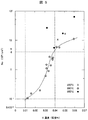
- oxide number density N O is a graph showing the O concentration dependency of the average oxide number density N O. It shows the O concentration dependence of the average oxide number density N 2 O including the results of 1) and 2).
- the average oxide number density N 2 O is logarithmic.
- the average oxide number density N O generally, tends to decrease with O concentration decreases, because O is present as a constituent atoms of the oxide, the average oxide number density N O and O concentration of relationships Is not simple. Even when the O concentration is the same, the average oxide number density N O shows a different value if the oxide size distribution is different.
- FIG. 5 shows that the hydrogen reduction heat treatment at 890 ° C. reduces the average oxide number density N 2 O compared to the hydrogen reduction heat treatment at 850 ° C. or 950 ° C. for the investigated powder.
- V, Nb, or by the addition of Ti, it is possible to obtain the value of stable low average oxide number density N O.
- Example 3 the magnetic properties of the water atomized Fe powder according to the present invention as a dust core were confirmed.
- Each powder subjected to hydrogen reduction heat treatment was immersed in a phosphate aqueous solution, mixed with a mixer, and then dried in the atmosphere at 200 ° C. to form an insulating film of iron phosphate glass on the powder surface.
- On the iron phosphate glass insulating film it was further coated with a silicone resin to form a two-layer coating.
- the silicone resin layer was formed by mixing a solution obtained by diluting silicone with toluene and the iron phosphate glass insulating film Fe powder, and then drying at 80 ° C. In this way, a composite powder with insulating coating was produced.
- a chenolube lubricant was added to the composite powder that was insulation-coated on these two layers, and the mixture was pressure-molded at a pressure of 1180 MPa at room temperature to prepare a dust magnetic material.
- the density was measured by the Archimedes method, and 7.55 g / cm 3 or more was obtained for all the powder magnetic materials.
- no. 1 a powder compact produced from a powder subjected to hydrogen reduction heat treatment at 890 ° C. and 4.5 h to 12.0 h showed a density of 7.65 g / cm 3 to 7.70 g / cm 3 .
- the shapes of these molded bodies were ring shapes having an outer diameter of 50 mm, an inner diameter of 40 mm, and a thickness of 5 mm.
- the nm scale analysis in the vicinity of the interface between the green compacts inside the molded body was performed using a field emission type transmission electron microscope HF-2000 (200 kV) manufactured by Hitachi, Ltd.
- the interface consists of an organic layer of Fe powder / iron phosphate glass insulating layer / C, O composition, and a small amount of oxide remaining in the vicinity of the surface of the above-mentioned hydrogen reduction heat-treated elementary powder is found on the Fe powder side. There wasn't. It was judged that most of the oxide disappeared due to the formation reaction of the iron phosphate glass insulating layer and was sufficiently reduced.
- the magnetic characteristics of the dust magnetic material were evaluated by the coercive force Hc and the iron loss W.
- the coercive force Hc is obtained by applying a winding of primary and secondary coils, and using the ring-shaped molded body having a strain relief heat treatment temperature of 550 ° C. and 600 ° C. It was obtained from the hysteresis curve measured by -5A-PC).
- the maximum measurement magnetic field is 10 kA / m, and the coercive force Hc (A / m) at this time is shown in Table 2.
- the iron loss W was measured on the same ring-shaped molded body with an AC magnetic measuring machine (BH analyzer BH4900-103 manufactured by Tesla). The measurement was carried out on a compact subjected to heat treatment at 550 ° C. under excitation conditions of a frequency of 400 Hz and a magnetic field of 1T.
- the measured values of iron loss W (W / kg) are also shown in Table 2.
- Figure 6 is a graph showing the average oxide number density N O dependency of the coercive force Hc. From Table 2, as shown in FIG. 6, the relationship between the average oxide number density N O and coercive force Hc was obtained.
- the average oxide number density N 2 O is logarithmic.
- the coercive force Hc is a value of a ring-shaped dusty magnetic material that has been heat-treated at 550 ° C. No. 1 and No. In No. 4, in the powder magnetic body subjected to the strain relief heat treatment at a higher temperature of 600 ° C., the recrystallization progressed further and the strain relief effect was improved, and a coercive force Hc value lower than 550 ° C. was obtained.
- the curve showing the average oxide number density N O dependency of the coercive force Hc of Figure 6 the average oxide number density N O is 0.1 ⁇ 10 9 / cm 2 or more, in the range of 4x10 9 / cm 2 or less, It can be seen that the coercive force Hc can be 210 A / m or less equivalent to the magnetic steel sheet magnetic core. Further, it is expected that the coercive force Hc can be reduced to 140 A / m.
- the coercive force Hc can achieve the following 210A / m, can be reduced to 140A / m near.
- the iron loss W is the sum of a hysteresis loss that is approximately proportional to the coercive force Hc and an eddy current loss that particularly depends on the characteristics of the insulation coating, and tends to decrease as the coercive force Hc decreases.
- the iron loss W can be set to 40 W / kg or less under the excitation conditions of a frequency of 400 Hz and a magnetic field of 1T.
- Fe powder, powdered magnetic material, and production methods thereof according to the present invention are used for general electromagnetic parts such as motor cores, electromagnetic valves, or reactors.
Landscapes
- Chemical & Material Sciences (AREA)
- Engineering & Computer Science (AREA)
- Materials Engineering (AREA)
- Mechanical Engineering (AREA)
- Metallurgy (AREA)
- Organic Chemistry (AREA)
- Power Engineering (AREA)
- Dispersion Chemistry (AREA)
- Manufacturing & Machinery (AREA)
- Powder Metallurgy (AREA)
- Manufacture Of Metal Powder And Suspensions Thereof (AREA)
- Soft Magnetic Materials (AREA)
Abstract
L'invention porte sur une poudre magnétique avec laquelle il est possible d'améliorer la moulabilité par compression, d'améliorer l'aptitude de récupération thermique après la contrainte d'un article moulé et d'améliorer les propriétés magnétiques. L'invention porte aussi sur un compact magnétique. La poudre de fer pour un compact magnétique comprend un élément métallique dont le composant principal est le fer et qui est produit par le procédé d'atomisation à l'eau. La poudre de fer représente 99,7 % en masse ou plus de fer, 0,002 % en masse ou moins de carbone, 0,001 % en masse ou moins d'azote et entre 0,01 % en masse et 0,04 % en masse d'oxygène sous la forme de particules d'oxyde. Les particules d'oxyde comprennent des particules formées à partir d'un élément métallique et d'oxygène. La densité numérique des particules d'oxyde ayant un diamètre moyen de particule de 2 nm ou plus et comprise entre 0,1 x 10⁹/cm² et 4 x 10⁹/cm², comme densité de surface moyenne dans la section transversale de la poudre de fer.
Applications Claiming Priority (2)
| Application Number | Priority Date | Filing Date | Title |
|---|---|---|---|
| JP2012007021A JP2013149661A (ja) | 2012-01-17 | 2012-01-17 | 圧粉磁性体用の鉄粉、圧粉磁性体、圧粉磁性体用の鉄粉の製造方法、及び圧粉磁性体の製造方法 |
| JP2012-007021 | 2012-01-17 |
Publications (1)
| Publication Number | Publication Date |
|---|---|
| WO2013108642A1 true WO2013108642A1 (fr) | 2013-07-25 |
Family
ID=48799070
Family Applications (1)
| Application Number | Title | Priority Date | Filing Date |
|---|---|---|---|
| PCT/JP2013/050031 Ceased WO2013108642A1 (fr) | 2012-01-17 | 2013-01-07 | Poudre de fer pour compact magnétique, compact magnétique, procédé de production d'une poudre de fer pour compact magnétique et procédé de production d'un compact magnétique |
Country Status (2)
| Country | Link |
|---|---|
| JP (1) | JP2013149661A (fr) |
| WO (1) | WO2013108642A1 (fr) |
Cited By (1)
| Publication number | Priority date | Publication date | Assignee | Title |
|---|---|---|---|---|
| JP2017188588A (ja) * | 2016-04-06 | 2017-10-12 | 株式会社村田製作所 | コイル部品 |
Families Citing this family (2)
| Publication number | Priority date | Publication date | Assignee | Title |
|---|---|---|---|---|
| KR102023112B1 (ko) * | 2013-04-19 | 2019-09-19 | 제이에프이 스틸 가부시키가이샤 | 압분 자심용 철분 및 압분 자심용 절연 피복 철분 |
| JP6520688B2 (ja) * | 2015-12-15 | 2019-05-29 | Tdk株式会社 | 磁性シート |
Citations (3)
| Publication number | Priority date | Publication date | Assignee | Title |
|---|---|---|---|---|
| JP2009302165A (ja) * | 2008-06-11 | 2009-12-24 | Tamura Seisakusho Co Ltd | 圧粉磁心及びその製造方法 |
| JP2010010673A (ja) * | 2008-05-30 | 2010-01-14 | Hitachi Ltd | 圧粉磁性体用軟磁性粉末およびそれを用いた圧粉磁性体 |
| JP2011202213A (ja) * | 2010-03-25 | 2011-10-13 | Hitachi Ltd | 圧粉磁性体用軟磁性粉末、それを用いた圧粉磁性体および製造方法 |
-
2012
- 2012-01-17 JP JP2012007021A patent/JP2013149661A/ja active Pending
-
2013
- 2013-01-07 WO PCT/JP2013/050031 patent/WO2013108642A1/fr not_active Ceased
Patent Citations (3)
| Publication number | Priority date | Publication date | Assignee | Title |
|---|---|---|---|---|
| JP2010010673A (ja) * | 2008-05-30 | 2010-01-14 | Hitachi Ltd | 圧粉磁性体用軟磁性粉末およびそれを用いた圧粉磁性体 |
| JP2009302165A (ja) * | 2008-06-11 | 2009-12-24 | Tamura Seisakusho Co Ltd | 圧粉磁心及びその製造方法 |
| JP2011202213A (ja) * | 2010-03-25 | 2011-10-13 | Hitachi Ltd | 圧粉磁性体用軟磁性粉末、それを用いた圧粉磁性体および製造方法 |
Cited By (1)
| Publication number | Priority date | Publication date | Assignee | Title |
|---|---|---|---|---|
| JP2017188588A (ja) * | 2016-04-06 | 2017-10-12 | 株式会社村田製作所 | コイル部品 |
Also Published As
| Publication number | Publication date |
|---|---|
| JP2013149661A (ja) | 2013-08-01 |
Similar Documents
| Publication | Publication Date | Title |
|---|---|---|
| JP5308916B2 (ja) | 圧粉磁性体用軟磁性粉末およびそれを用いた圧粉磁性体 | |
| US11011305B2 (en) | Powder magnetic core, and coil component | |
| JP6942379B2 (ja) | 磁性材料とその製造法 | |
| KR101482816B1 (ko) | 표면 개질된 희토류계 소결 자석의 제조 방법 및 표면 개질된 희토류계 소결 자석 | |
| JP6088284B2 (ja) | 軟磁性混合粉末 | |
| JP6669304B2 (ja) | 結晶質Fe基合金粉末及びその製造方法 | |
| EP3690071B1 (fr) | Matériau magnétique et procédé pour la production de celui-ci | |
| WO2008093430A1 (fr) | Poudre de fer à compressibilité élevée, poudre de fer la comprenant pour un noyau à poudre de fer, et noyau à poudre de fer | |
| WO2017164375A1 (fr) | Matériau magnétique et son procédé de fabrication | |
| JP2014502034A5 (fr) | ||
| JP6942343B2 (ja) | 磁性材料およびその製造方法 | |
| JP2008028162A (ja) | 軟磁性材料の製造方法、軟磁性材料、および圧粉磁心 | |
| US11331721B2 (en) | Magnetic material and process for manufacturing same | |
| JP6037213B2 (ja) | 表面改質されたR−Fe−B系焼結磁石の製造方法 | |
| JP5427664B2 (ja) | 圧粉磁性体用軟磁性粉末、それを用いた圧粉磁性体および製造方法 | |
| JP2019178402A (ja) | 軟磁性粉末 | |
| JP2009164317A (ja) | 軟磁性複合圧密コアの製造方法。 | |
| JP2010222670A (ja) | 複合磁性材料 | |
| WO2013108642A1 (fr) | Poudre de fer pour compact magnétique, compact magnétique, procédé de production d'une poudre de fer pour compact magnétique et procédé de production d'un compact magnétique | |
| JP2005303006A (ja) | 圧粉磁心の製造方法および圧粉磁心 | |
| JP2007092162A (ja) | 高圧縮性鉄粉、およびそれを用いた圧粉磁芯用鉄粉と圧粉磁芯 | |
| JP7001259B2 (ja) | 磁性材料およびその製造法 | |
| JP2010232357A (ja) | 表面改質された希土類系焼結磁石の製造方法 | |
| JP2007027320A (ja) | 軟磁性材料、圧粉磁心、および軟磁性材料の製造方法 | |
| JP5262902B2 (ja) | 表面改質された希土類系焼結磁石の製造方法 |
Legal Events
| Date | Code | Title | Description |
|---|---|---|---|
| 121 | Ep: the epo has been informed by wipo that ep was designated in this application |
Ref document number: 13739021 Country of ref document: EP Kind code of ref document: A1 |
|
| 122 | Ep: pct application non-entry in european phase |
Ref document number: 13739021 Country of ref document: EP Kind code of ref document: A1 |
|
| NENP | Non-entry into the national phase |
Ref country code: DE |