WO2013108655A1 - Appareil de fourniture de partie de type vibrante - Google Patents
Appareil de fourniture de partie de type vibrante Download PDFInfo
- Publication number
- WO2013108655A1 WO2013108655A1 PCT/JP2013/050091 JP2013050091W WO2013108655A1 WO 2013108655 A1 WO2013108655 A1 WO 2013108655A1 JP 2013050091 W JP2013050091 W JP 2013050091W WO 2013108655 A1 WO2013108655 A1 WO 2013108655A1
- Authority
- WO
- WIPO (PCT)
- Prior art keywords
- component
- separation
- parts
- separation container
- supply device
- Prior art date
- Legal status (The legal status is an assumption and is not a legal conclusion. Google has not performed a legal analysis and makes no representation as to the accuracy of the status listed.)
- Ceased
Links
Images




Classifications
-
- B—PERFORMING OPERATIONS; TRANSPORTING
- B65—CONVEYING; PACKING; STORING; HANDLING THIN OR FILAMENTARY MATERIAL
- B65G—TRANSPORT OR STORAGE DEVICES, e.g. CONVEYORS FOR LOADING OR TIPPING, SHOP CONVEYOR SYSTEMS OR PNEUMATIC TUBE CONVEYORS
- B65G47/00—Article or material-handling devices associated with conveyors; Methods employing such devices
- B65G47/02—Devices for feeding articles or materials to conveyors
- B65G47/04—Devices for feeding articles or materials to conveyors for feeding articles
- B65G47/12—Devices for feeding articles or materials to conveyors for feeding articles from disorderly-arranged article piles or from loose assemblages of articles
- B65G47/14—Devices for feeding articles or materials to conveyors for feeding articles from disorderly-arranged article piles or from loose assemblages of articles arranging or orientating the articles by mechanical or pneumatic means during feeding
- B65G47/1407—Devices for feeding articles or materials to conveyors for feeding articles from disorderly-arranged article piles or from loose assemblages of articles arranging or orientating the articles by mechanical or pneumatic means during feeding the articles being fed from a container, e.g. a bowl
- B65G47/1414—Devices for feeding articles or materials to conveyors for feeding articles from disorderly-arranged article piles or from loose assemblages of articles arranging or orientating the articles by mechanical or pneumatic means during feeding the articles being fed from a container, e.g. a bowl by means of movement of at least the whole wall of the container
- B65G47/1421—Vibratory movement
Definitions
- the present invention relates to an oscillating component supply device that supplies components that are easily entangled such as coil springs in a separated state.
- Two troughs that convey parts in opposite directions are arranged in parallel as a vibration-type parts supply device suitable for aligning parts that are easily entangled with each other, such as small coil springs, in one row and one layer, and supplying them to the next process.
- a component feeder that separates components that are intertwined with each other is incorporated into the return feeder arranged in (see Patent Document 1).
- the component supply apparatus described in the above-mentioned Patent Document 1 aligns while conveying components, arranges an aligned supply trough that supplies the aligned components to the next process, and arranges the unaligned components in parallel with the aligned supply trough.
- a return trough that conveys in the opposite direction to the aligned supply trough and supplies it to the upstream side of the aligned supply trough, and sorts the parts intertwined with each other on the downstream side of the return trough and sends them to the component separation device, The parts are separated one by one by the parts separating device and returned to the alignment supply trough, so that the parts can be efficiently aligned and supplied to the next process.
- the component separation device incorporated in this component supply device is attached to the upper surface of a vertically placed cylindrical separation container by placing a rotating disk driven by a motor on the bottom and rotating the rotating disk.
- the blade is spun off by the blade and swung in the separation container, and the entanglement is released by expanding and contracting or bending the component.
- the inlet of the separation container is provided on the side wall, but the outlet is provided in a portion projecting in the radial direction of the upper lid that closes the upper opening of the separation container.
- the component supply device since the discharge port of the separation container of the component separation device is located at a high position, the component supply device has a large height as a whole, and there is a problem that a large space is required in the height direction.
- the parts that have jumped out from the discharge port are likely to be scattered outside the alignment supply trough because the drop from the discharge port of the separation container to the conveying path of the alignment supply trough is large.
- the separation container 51 has a laterally tapered cylindrical shape, and an air outlet 52 is provided at the bottom of the large diameter side.
- the components are swirled by the air ejected from the outlet 52 and separated by colliding with a protruding member 53 attached to the inner surface of the separation container 51.
- the inlet 54 of components is provided in the small diameter side wall of the separation container 51, and the discharge port 56 is provided in the lid
- the discharge port 56 of the separation container 51 is formed so as to extend obliquely downward from the large-diameter side lid 55, and the components that are still intertwined are easily discharged. And since the components discharged while being intertwined are eliminated by the alignment supply trough, there is a risk that the capability of supplying components will be reduced.
- JP 2007-161360 A Japanese Patent No. 3692458
- an object of the present invention is to provide a compact vibration component supply device that can stably supply components that are easily entangled with each other.
- the present invention provides an alignment supply trough that aligns while conveying parts and supplies the aligned parts to the next process, and is arranged in parallel with the alignment supply trough to align unaligned parts.
- a return feeder provided with a return trough that is conveyed in the opposite direction to the supply trough and supplied to the upstream side of the aligned supply trough, inside the separation container provided in the middle of the conveying path of the aligned supply trough or the return trough,
- the discharge port of the separation container of the component separation device extends obliquely upward from the side wall of the separation container. It was formed.
- the position of the discharge port of the separation container can be lowered without increasing the number of parts to be removed on the downstream side of the part separation device.
- the components discharged from the discharge port can be prevented from being scattered, the components can be stably aligned and supplied, and the height of the component separating device and thus the entire vibration component supplying device can be reduced.
- the inclination angle of the outlet of the separation container is preferably 30 to 60 °.
- the discharge amount is adjusted according to the amount of parts discharged from the separation container and the proportion of the parts that are intertwined. By adjusting the opening area of the outlet, parts can be arranged and supplied more efficiently.
- the length dimension of the separation container is made smaller than the inner diameter dimension, the entire component supply device can be made more compact.
- the component separation device examples include a device that rotates components with air ejected from the inner surface of the separation container (hereinafter, this separation method is referred to as an “air type”), and a rotating body that is disposed at the bottom of the separation container. It is possible to employ a component that turns the component by rotating (hereinafter, this separation method is referred to as “rotation type”).
- the component separation device may be installed in a conveyance path in the vicinity of the upstream side of the component alignment portion of the alignment supply trough so that the components separated by the component separation device are aligned before they are entangled again.
- the component separation device By installing a plurality of devices and increasing the component separation capability, it becomes possible to more efficiently align and supply the components, thereby improving the component supply capability.
- install the component separators so that two of them are adjacent to each other in the component transport direction.
- the upstream component separator is an air type
- the downstream component separator is It is good to use a rotary type. This is because a low-cost pneumatic type can be arranged on the upstream side and a rotary type having a high component separation performance can be arranged on the downstream side, so that the component separation ability can be improved while suppressing an increase in cost.
- a component detection sensor is provided in the vicinity of the upstream side and the downstream side of the separation container of the component separation device, and the amount of parts staying in the separation container is managed based on the detection result of each of these component detection sensors.
- a part for blowing air from the side to the parts on the conveying path or an arm attached to the piezoelectric actuator on the conveying path can be employ
- the width of the conveyance path in the vicinity of the upstream side of the component separator is set to be not more than three times the diameter of the coil spring, and a certain amount in the vicinity of the upstream side of the component separator.
- the vibratory component supply device of the present invention is formed such that the separation container discharge port of the component separation device provided in the middle of the return feeder conveyance path extends obliquely upward from the side wall of the separation container. Because the parts that remain intertwined are not easily discharged from the separation container, the position of the discharge port of the separation container is lowered without increasing the number of parts that are eliminated downstream of the part separation device. The components discharged from the discharge port can be prevented from being scattered, the components can be stably aligned, and the entire apparatus can be made compact in the height direction.
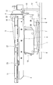
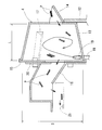
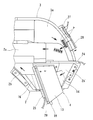
- External appearance perspective view of the component supply apparatus of 1st Embodiment Plan view of FIG. Front view of FIG. 1 is a longitudinal sectional view of a component separating apparatus incorporated in the component supply apparatus of FIG.
- the top view which shows the example which provided the component exclusion means in the upstream of the component separation apparatus of FIG.
- the top view which shows the example which provided another component exclusion means in the upstream of the component separation apparatus of FIG.
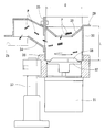
- the longitudinal cross-sectional view of the component separation apparatus integrated in the component supply apparatus of 2nd Embodiment The top view of the component supply apparatus of 3rd Embodiment Longitudinal sectional view of a conventional parts separator
- the vibration type component supply apparatus is configured to convey small coil springs P (hereinafter referred to as “components P”) in opposite directions by vibration transmitted from the excitation mechanism 1.
- a return feeder having a supply trough 2 and a return trough 3 incorporates a parts separating device 4 that separates the parts P intertwined into each other one by one.
- the vibration mechanism 1 includes a lower vibrating body 7 attached to a base 5 via a vibration isolating rubber 6, a counterweight 8 fixed to the lower vibrating body 7, and an upper vibrating body connected to the alignment supply trough 2. 9, an electromagnet and a movable iron core (both not shown) arranged oppositely between both vibrating bodies 7, 9, a leaf spring 10 connecting both vibrating bodies 7, 9, the upper vibrating body 9 and the return trough 3.
- the plate feed trough 2 and the return trough 3 are vibrated by the action of an electromagnet and a movable iron core.
- the alignment supply trough 2 conveys the component P to the left side of the drawings in FIGS. 2 and 3 by two rows of conveyance paths 2a and 2b due to vibration transmitted from the excitation mechanism 1.
- the inner conveyance path 2a is for sending the parts P introduced from the hopper (not shown) and the parts P removed from the outer conveyance path 2b to the upstream side of the return trough 3.
- the outer conveyance path 2b supplies parts P sent from the downstream side of the return trough 3 so that their postures are aligned and supplies them to the next process.
- a separation device 4 is provided.
- shoot part 11 which forms the downstream part of the outer conveyance path 2b is provided in the downstream of the components separation apparatus 4.
- the return trough 3 conveys the parts P sent from the inner conveyance path 2a of the alignment supply trough 2 to the right side of the drawings in FIGS. This is sent to the upstream portion 2b ′ of the conveying path 2b outside the trough 2.
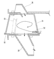
- the component separation device 4 is an air-type device having a laterally tapered cylindrical separation container 13 attached to a support column 12 erected on a base 5.
- the separation container 13 is formed such that the length L is smaller than the inner diameter D
- the inlet 14 is formed on the small-diameter side wall
- the outlet 15 is formed on the lid 15 that forms the large-diameter side wall. 16 are provided.
- a protruding member 17 having a triangular cross section extending in the axial direction is attached to the upper part of the inner surface of the separation container 13, and the tip of the air supply pipe 18 is inserted into the bottom of the large diameter side.
- Air is ejected from the ejection port 19 in a direction in contact with the circumferential direction of the inner surface of the separation container 13.
- a discharge amount adjusting plate 20 that slides in the direction to open and close the discharge port 16 is attached to the large-diameter side lid 15 of the separation container 13, and the discharge area of the component P is adjusted by adjusting the opening area of the discharge port 16. It can be adjusted.
- the discharge port 16 of the separation container 13 extends in a cylindrical shape obliquely upward from the large-diameter side lid (side wall) 15 at an inclination angle of about 35 °, and is closed at the top and side at the tip side.
- the component P is discharged downward.
- the inclination angle of the discharge port 16 is preferably set in the range of 30 to 60 °.
- the parts P put into the inner conveyance path 2a of the alignment supply trough 2 are once conveyed to the left side of the drawing and sent to the return trough 3, and then conveyed to the right side of the drawing and sent to the outer conveyance path 2b of the alignment supply trough 2. It is done.
- the parts sent to the upstream portion 2 b ′ of the outer conveyance path 2 b of the alignment supply trough 2 are first put into the separation container 13 of the parts separation device 4.
- the parts P thrown in from the inlet 14 of the separation container 13 are blown up by the air ejected from the air outlet 19 and swivel inside the separation container 13, colliding with the protruding member 17 during the turning, and one by one.
- the separated part P becomes lighter than the entangled ones, and the spring elasticity restrained by the entanglement is recovered and easily springs up, and is discharged easily from the discharge port 16 and returned to the outer conveyance path 2b.
- the parts P returned to the outer conveyance path 2b are sent to the chute part 11, aligned by the parts aligning part 21 provided in the chute part 11, and then sent to the next process through the gate part 22.
- the component aligning unit 21 returns the intertwined component P to the inner conveyance path 2a.
- the chute part 11 of the alignment supply trough 2 is provided with an air nozzle (both not shown) and a part confirmation sensor 23 for injecting air from the upstream side and the downstream side toward the gate part 22.
- the air nozzle on the upstream side ejects air that assists the component P so as to smoothly pass through the gate portion 22.
- the air nozzle on the downstream side ejects air to prevent entry of the part P into the gate part 22 when the part confirmation sensor 23 determines that the part P in the downstream part of the chute part 11 is full.
- the component confirmation sensor 23 does not detect the component P for a predetermined time, the air is jetted for a short time to eliminate the component clogging at the gate portion 22.
- This component supply device has the above-described configuration, and the discharge port 16 of the separation container 13 of the component separation device 4 incorporated in the return feeder extends obliquely upward from the lid 15 that forms the large-diameter side wall of the separation container 13. Since it formed in this way, the components P which are still intertwined are not easily discharged from the separation container 13.
- the position of the discharge port 16 of the separation container 13 can be lowered without increasing the number of parts P excluded on the downstream side of the parts separator 4.
- a drop from the discharge port 16 of the separation container 13 to the outer conveyance path 2b of the alignment supply trough 2 can be reduced, so that the parts P discharged from the discharge port 16 can be prevented from being scattered and the components P can be stably aligned.
- the height of the component separation apparatus 4 and by extension, the whole component supply apparatus can be reduced.
- the discharge port 16 depends on the amount of the parts P discharged from the separation container 13 and the proportion of the parts P that are still intertwined. By adjusting the opening area, parts P can be arranged and supplied more efficiently.
- the component separating device 4 is installed in the vicinity of the upstream side of the component aligning portion 21 of the alignment supply trough 2 so that the components P separated by the component separating device 4 are aligned before being entangled again. The supply capacity is improved.
- the installation space can be reduced by downsizing in the height direction without reducing the component supply capability. Further, the entire apparatus is made compact by forming the length L of the separation container 13 smaller than the inner diameter D.
- FIG. 5 and FIG. 6 show examples in which the components supply apparatus of the first embodiment described above is added with a configuration for appropriately maintaining the component retention amount in the separation container 13 of the component separation apparatus 4.
- component detection sensors 24 and 25 are provided at the boundary portion between the upstream end of the alignment supply trough 2 and the downstream end of the return trough 3 and the upper portion of the discharge port 16 of the separation container 13, and the return conveyance of the downstream end of the return trough 3 is performed.
- An air nozzle 26 for blowing air from the side of the part P on the path 3a is provided. Based on the detection results of the component detection sensors 24 and 25, the component retention amount in the separation container 13 is managed. When the component retention amount exceeds a predetermined value, air is ejected from the air nozzle 26.
- Air is blown onto the part P that is about to pass therethrough, and the part P is removed from the return conveyance path 3a and returned to the inner conveyance path 2a of the alignment supply trough 2.
- the amount of parts staying in the separation container 13 can be maintained appropriately, and troubles of the parts separation device 4 itself, deformation, scratches, breakage, etc. of the parts P can be prevented.
- an arm 28 attached to the piezoelectric actuator 27 is used instead of the air nozzle 26 of FIG.
- a component that presses the part P on the conveyance path 3a from the side is adopted so that the same effect as in the example of FIG. 5 can be obtained.
- the downstream end of the return trough 3, that is, the width of the return conveyance path 3a in the vicinity of the upstream side of the component separating device 4 is formed to be not more than three times the diameter of the component P to separate components.
- a certain amount of the parts P is excluded in the vicinity of the upstream side of the device 4, and this also limits the amount of parts to be put into the separation container 13, causing troubles in the parts separating device 4 itself and problems in the parts P. The prevention of the occurrence of this is attempted.
- FIG. 7 shows a component separation device 29 incorporated in the component supply device of the second embodiment.
- This component separation device 29 is a rotary type in which a rotating disk (rotating body) 32 driven by a motor 31 is disposed at the bottom of a vertically placed cylindrical separation container 30.
- the separation container 30 has a length (height) dimension L smaller than the inner diameter dimension D, and is provided with an input port 33 at the top and a discharge port 34 at the side wall. Further, a discharge amount adjusting plate 35 that slides in a direction to open and close the discharge port 34 is attached to the side wall of the separation container 30, and the discharge area of the component P can be adjusted by adjusting the opening area of the discharge port 34.
- a support cylinder 36 into which the lower end portion of the separation container 30 is fitted is attached to a support column 37 erected on the base 5.
- the rotating disk 32 is rotated in the separation container 30, and the blade P attached to the upper surface of the component separation device 29 jumps off the component P introduced from the insertion port 33 and turns.
- the parts P are expanded and contracted or bent to be separated one by one and discharged from the discharge port 34.
- the discharge port 34 of the separation container 30 extends in a cylindrical shape obliquely upward from the side wall at an inclination angle of about 35 °, as in the case of the first embodiment, and covers the upper side and the side at the tip side.
- the part P is formed to be discharged downward. Therefore, the component supply device of the second embodiment that incorporates the rotary component separation device 29 instead of the pneumatic component separation device 4 of the first embodiment is compact in the height direction without reducing the component supply capability. To reduce the installation space.
- FIG. 8 shows a component supply apparatus according to the third embodiment.
- the installation position of the pneumatic component separation device 4 of the first embodiment is changed to the downstream end of the return trough 3, and at the upstream portion of the alignment supply trough 2 where the component separation device 4 was installed,
- the rotary component separation device 29 of the second embodiment is installed.
- the parts P are returned by air to the conveying path.
- An air nozzle 26 excluded from 3a is provided.
- a component sorting unit 39 that sorts the component P discharged from the pneumatic component separation device 4 is provided upstream of the alignment supply trough 2.
- This parts selection part 39 sends the parts P separated one by one to the chute part 11 as it is by blowing air from the side to the parts P conveyed by the chute-like feed path 40, The parts P that are still intertwined are put into the rotary part separator 29.
- a low-cost pneumatic component separation device 4 is installed on the upstream side in the component conveyance direction, and a rotary component separation device having high component separation performance so as to be adjacent to this downstream side. 29 is installed, so that the parts separation capability is increased and the parts P can be arranged and supplied more efficiently, while suppressing the increase in cost, and the parts supply capacity is improved compared to the first and second embodiments. Can be achieved.
- the present invention is not limited to the coil spring that is the target of alignment supply in each of the above-described embodiments, and can be effectively applied to a vibration-type component supply device that targets easily entangled components.
Landscapes
- Engineering & Computer Science (AREA)
- Mechanical Engineering (AREA)
- Feeding Of Articles To Conveyors (AREA)
- Special Conveying (AREA)
- Jigging Conveyors (AREA)
Applications Claiming Priority (2)
| Application Number | Priority Date | Filing Date | Title |
|---|---|---|---|
| JP2012006020A JP5956160B2 (ja) | 2012-01-16 | 2012-01-16 | 振動式部品供給装置 |
| JP2012-006020 | 2012-01-16 |
Publications (1)
| Publication Number | Publication Date |
|---|---|
| WO2013108655A1 true WO2013108655A1 (fr) | 2013-07-25 |
Family
ID=48799083
Family Applications (1)
| Application Number | Title | Priority Date | Filing Date |
|---|---|---|---|
| PCT/JP2013/050091 Ceased WO2013108655A1 (fr) | 2012-01-16 | 2013-01-08 | Appareil de fourniture de partie de type vibrante |
Country Status (2)
| Country | Link |
|---|---|
| JP (1) | JP5956160B2 (fr) |
| WO (1) | WO2013108655A1 (fr) |
Cited By (7)
| Publication number | Priority date | Publication date | Assignee | Title |
|---|---|---|---|---|
| CN106865233A (zh) * | 2015-10-02 | 2017-06-20 | 黄镇镐 | 压缩螺旋弹簧的分离供给装置 |
| CN109775313A (zh) * | 2018-12-28 | 2019-05-21 | 东莞市宇讯电子科技有限公司 | 一种rfid的弹簧式天线的自动上料装置 |
| CN110239940A (zh) * | 2019-07-25 | 2019-09-17 | 迈得医疗工业设备股份有限公司 | 分离装置以及分离方法 |
| CN110356849A (zh) * | 2019-07-25 | 2019-10-22 | 迈得医疗工业设备股份有限公司 | 分离装置 |
| CN110524218A (zh) * | 2019-09-26 | 2019-12-03 | 广东坚士制锁有限公司 | 一种弹簧吹气排料设备 |
| CN115610957A (zh) * | 2022-10-31 | 2023-01-17 | 成都毕普智造科技有限公司 | 一种卡圈自动分料机构及设备 |
| CN118577487A (zh) * | 2023-03-02 | 2024-09-03 | 精工爱普生株式会社 | 弹簧分离供给装置 |
Families Citing this family (2)
| Publication number | Priority date | Publication date | Assignee | Title |
|---|---|---|---|---|
| KR101562352B1 (ko) * | 2014-08-18 | 2015-10-22 | 새한전자(주) | 스프링을 분리하여 공급하는 장치 |
| CN113223396B (zh) * | 2021-05-13 | 2021-11-09 | 深圳市技成科技有限公司 | 一种新型plc及组态软件教学培训装置 |
Citations (6)
| Publication number | Priority date | Publication date | Assignee | Title |
|---|---|---|---|---|
| JPS4838834B1 (fr) * | 1968-09-24 | 1973-11-20 | ||
| JPS5437332B2 (fr) * | 1976-06-04 | 1979-11-14 | ||
| JPH08188229A (ja) * | 1995-01-11 | 1996-07-23 | Shinko Electric Co Ltd | コイルばね供給装置 |
| JP2000016571A (ja) * | 1998-06-26 | 2000-01-18 | Daizen:Kk | 物品供給装置 |
| JP3692458B2 (ja) * | 2002-05-23 | 2005-09-07 | 哲也 朝田 | コイルばね分離装置 |
| JP2007161360A (ja) * | 2005-12-09 | 2007-06-28 | Ntn Corp | 振動式部品供給装置 |
-
2012
- 2012-01-16 JP JP2012006020A patent/JP5956160B2/ja not_active Expired - Fee Related
-
2013
- 2013-01-08 WO PCT/JP2013/050091 patent/WO2013108655A1/fr not_active Ceased
Patent Citations (6)
| Publication number | Priority date | Publication date | Assignee | Title |
|---|---|---|---|---|
| JPS4838834B1 (fr) * | 1968-09-24 | 1973-11-20 | ||
| JPS5437332B2 (fr) * | 1976-06-04 | 1979-11-14 | ||
| JPH08188229A (ja) * | 1995-01-11 | 1996-07-23 | Shinko Electric Co Ltd | コイルばね供給装置 |
| JP2000016571A (ja) * | 1998-06-26 | 2000-01-18 | Daizen:Kk | 物品供給装置 |
| JP3692458B2 (ja) * | 2002-05-23 | 2005-09-07 | 哲也 朝田 | コイルばね分離装置 |
| JP2007161360A (ja) * | 2005-12-09 | 2007-06-28 | Ntn Corp | 振動式部品供給装置 |
Cited By (9)
| Publication number | Priority date | Publication date | Assignee | Title |
|---|---|---|---|---|
| CN106865233A (zh) * | 2015-10-02 | 2017-06-20 | 黄镇镐 | 压缩螺旋弹簧的分离供给装置 |
| CN109775313A (zh) * | 2018-12-28 | 2019-05-21 | 东莞市宇讯电子科技有限公司 | 一种rfid的弹簧式天线的自动上料装置 |
| CN110239940A (zh) * | 2019-07-25 | 2019-09-17 | 迈得医疗工业设备股份有限公司 | 分离装置以及分离方法 |
| CN110356849A (zh) * | 2019-07-25 | 2019-10-22 | 迈得医疗工业设备股份有限公司 | 分离装置 |
| CN110356849B (zh) * | 2019-07-25 | 2024-05-24 | 迈得医疗工业设备股份有限公司 | 分离装置 |
| CN110524218A (zh) * | 2019-09-26 | 2019-12-03 | 广东坚士制锁有限公司 | 一种弹簧吹气排料设备 |
| CN110524218B (zh) * | 2019-09-26 | 2024-06-07 | 广东坚士制锁有限公司 | 一种弹簧吹气排料设备 |
| CN115610957A (zh) * | 2022-10-31 | 2023-01-17 | 成都毕普智造科技有限公司 | 一种卡圈自动分料机构及设备 |
| CN118577487A (zh) * | 2023-03-02 | 2024-09-03 | 精工爱普生株式会社 | 弹簧分离供给装置 |
Also Published As
| Publication number | Publication date |
|---|---|
| JP2013144599A (ja) | 2013-07-25 |
| JP5956160B2 (ja) | 2016-07-27 |
Similar Documents
| Publication | Publication Date | Title |
|---|---|---|
| JP5956160B2 (ja) | 振動式部品供給装置 | |
| JP4944260B1 (ja) | ワーク供給装置 | |
| US8640852B2 (en) | Spring feeder | |
| US6782992B2 (en) | Vibratory parts-feeding unit | |
| KR20120106097A (ko) | 곡물탈곡기 | |
| US20160214801A1 (en) | Rotary hopper feeder for conveying and separating connection elements that have at least one shaft | |
| JP5400335B2 (ja) | 部品選別装置 | |
| JP2011139702A (ja) | 煙草加工産業の振動コンベアポットにおける紙除去 | |
| JP5419559B2 (ja) | スプリングフィーダー | |
| RU2376081C1 (ru) | Двухпродуктовый воздушно-гравитационный классификатор | |
| JPH11274797A (ja) | チップ状電子部品供給装置 | |
| JP5561990B2 (ja) | ニューマチックアンローダの先端ノズル用荷役促進装置 | |
| JP2015193436A (ja) | 振動式部品搬送装置 | |
| CA2936799C (fr) | Dispositif de separation d'un produit granulaire d'avec un flux d'air de transport | |
| KR100756082B1 (ko) | 고추씨 분리장치 | |
| KR101562352B1 (ko) | 스프링을 분리하여 공급하는 장치 | |
| JP2012224452A (ja) | 部品分離機構およびそれを用いた振動式部品供給装置 | |
| JP2014031273A (ja) | パーツほぐし装置及びこれを用いた供給装置 | |
| JP3781032B2 (ja) | キャップ状のワークの姿勢調整装置及び整列搬送装置 | |
| JP7140967B2 (ja) | 振動搬送装置 | |
| KR20230005550A (ko) | 스프링 분리 공급장치 | |
| JP5737579B2 (ja) | 小型部品の分離整列供給装置 | |
| JPH09267910A (ja) | 部品供給装置の絡み部品分離機構 | |
| JP6199691B2 (ja) | プリフォーム供給装置 | |
| WO2024101405A1 (fr) | Chargeur à ressort |
Legal Events
| Date | Code | Title | Description |
|---|---|---|---|
| 121 | Ep: the epo has been informed by wipo that ep was designated in this application |
Ref document number: 13738056 Country of ref document: EP Kind code of ref document: A1 |
|
| NENP | Non-entry into the national phase |
Ref country code: DE |
|
| 122 | Ep: pct application non-entry in european phase |
Ref document number: 13738056 Country of ref document: EP Kind code of ref document: A1 |