WO2013108702A1 - 凍結検出装置 - Google Patents
凍結検出装置 Download PDFInfo
- Publication number
- WO2013108702A1 WO2013108702A1 PCT/JP2013/050276 JP2013050276W WO2013108702A1 WO 2013108702 A1 WO2013108702 A1 WO 2013108702A1 JP 2013050276 W JP2013050276 W JP 2013050276W WO 2013108702 A1 WO2013108702 A1 WO 2013108702A1
- Authority
- WO
- WIPO (PCT)
- Prior art keywords
- liquid
- detection unit
- temperature
- temperature detection
- cooling
- Prior art date
- Legal status (The legal status is an assumption and is not a legal conclusion. Google has not performed a legal analysis and makes no representation as to the accuracy of the status listed.)
- Ceased
Links
Images



Classifications
-
- F—MECHANICAL ENGINEERING; LIGHTING; HEATING; WEAPONS; BLASTING
- F25—REFRIGERATION OR COOLING; COMBINED HEATING AND REFRIGERATION SYSTEMS; HEAT PUMP SYSTEMS; MANUFACTURE OR STORAGE OF ICE; LIQUEFACTION SOLIDIFICATION OF GASES
- F25D—REFRIGERATORS; COLD ROOMS; ICE-BOXES; COOLING OR FREEZING APPARATUS NOT OTHERWISE PROVIDED FOR
- F25D21/00—Defrosting; Preventing frosting; Removing condensed or defrost water
- F25D21/02—Detecting the presence of frost or condensate
-
- B—PERFORMING OPERATIONS; TRANSPORTING
- B67—OPENING, CLOSING OR CLEANING BOTTLES, JARS OR SIMILAR CONTAINERS; LIQUID HANDLING
- B67D—DISPENSING, DELIVERING OR TRANSFERRING LIQUIDS, NOT OTHERWISE PROVIDED FOR
- B67D1/00—Apparatus or devices for dispensing beverages on draught
- B67D1/08—Details
- B67D1/0857—Cooling arrangements
-
- F—MECHANICAL ENGINEERING; LIGHTING; HEATING; WEAPONS; BLASTING
- F25—REFRIGERATION OR COOLING; COMBINED HEATING AND REFRIGERATION SYSTEMS; HEAT PUMP SYSTEMS; MANUFACTURE OR STORAGE OF ICE; LIQUEFACTION SOLIDIFICATION OF GASES
- F25D—REFRIGERATORS; COLD ROOMS; ICE-BOXES; COOLING OR FREEZING APPARATUS NOT OTHERWISE PROVIDED FOR
- F25D31/00—Other cooling or freezing apparatus
- F25D31/002—Liquid coolers, e.g. beverage cooler
- F25D31/003—Liquid coolers, e.g. beverage cooler with immersed cooling element
-
- G—PHYSICS
- G01—MEASURING; TESTING
- G01K—MEASURING TEMPERATURE; MEASURING QUANTITY OF HEAT; THERMALLY-SENSITIVE ELEMENTS NOT OTHERWISE PROVIDED FOR
- G01K7/00—Measuring temperature based on the use of electric or magnetic elements directly sensitive to heat ; Power supply therefor, e.g. using thermoelectric elements
- G01K7/16—Measuring temperature based on the use of electric or magnetic elements directly sensitive to heat ; Power supply therefor, e.g. using thermoelectric elements using resistive elements
-
- G—PHYSICS
- G01—MEASURING; TESTING
- G01N—INVESTIGATING OR ANALYSING MATERIALS BY DETERMINING THEIR CHEMICAL OR PHYSICAL PROPERTIES
- G01N25/00—Investigating or analyzing materials by the use of thermal means
- G01N25/02—Investigating or analyzing materials by the use of thermal means by investigating changes of state or changes of phase; by investigating sintering
- G01N25/04—Investigating or analyzing materials by the use of thermal means by investigating changes of state or changes of phase; by investigating sintering of melting point; of freezing point; of softening point
- G01N25/06—Analysis by measuring change of freezing point
-
- B—PERFORMING OPERATIONS; TRANSPORTING
- B67—OPENING, CLOSING OR CLEANING BOTTLES, JARS OR SIMILAR CONTAINERS; LIQUID HANDLING
- B67D—DISPENSING, DELIVERING OR TRANSFERRING LIQUIDS, NOT OTHERWISE PROVIDED FOR
- B67D1/00—Apparatus or devices for dispensing beverages on draught
- B67D1/08—Details
- B67D1/0857—Cooling arrangements
- B67D1/0858—Cooling arrangements using compression systems
- B67D1/0859—Cooling arrangements using compression systems the evaporator being in direct heat contact with the beverage, e.g. placed inside a beverage container
-
- B—PERFORMING OPERATIONS; TRANSPORTING
- B67—OPENING, CLOSING OR CLEANING BOTTLES, JARS OR SIMILAR CONTAINERS; LIQUID HANDLING
- B67D—DISPENSING, DELIVERING OR TRANSFERRING LIQUIDS, NOT OTHERWISE PROVIDED FOR
- B67D1/00—Apparatus or devices for dispensing beverages on draught
- B67D1/08—Details
- B67D1/0878—Safety, warning or controlling devices
-
- B—PERFORMING OPERATIONS; TRANSPORTING
- B67—OPENING, CLOSING OR CLEANING BOTTLES, JARS OR SIMILAR CONTAINERS; LIQUID HANDLING
- B67D—DISPENSING, DELIVERING OR TRANSFERRING LIQUIDS, NOT OTHERWISE PROVIDED FOR
- B67D2210/00—Indexing scheme relating to aspects and details of apparatus or devices for dispensing beverages on draught or for controlling flow of liquids under gravity from storage containers for dispensing purposes
- B67D2210/00028—Constructional details
- B67D2210/00099—Temperature control
- B67D2210/00104—Cooling only
-
- F—MECHANICAL ENGINEERING; LIGHTING; HEATING; WEAPONS; BLASTING
- F25—REFRIGERATION OR COOLING; COMBINED HEATING AND REFRIGERATION SYSTEMS; HEAT PUMP SYSTEMS; MANUFACTURE OR STORAGE OF ICE; LIQUEFACTION SOLIDIFICATION OF GASES
- F25B—REFRIGERATION MACHINES, PLANTS OR SYSTEMS; COMBINED HEATING AND REFRIGERATION SYSTEMS; HEAT PUMP SYSTEMS
- F25B2700/00—Sensing or detecting of parameters; Sensors therefor
- F25B2700/11—Sensor to detect if defrost is necessary
-
- F—MECHANICAL ENGINEERING; LIGHTING; HEATING; WEAPONS; BLASTING
- F25—REFRIGERATION OR COOLING; COMBINED HEATING AND REFRIGERATION SYSTEMS; HEAT PUMP SYSTEMS; MANUFACTURE OR STORAGE OF ICE; LIQUEFACTION SOLIDIFICATION OF GASES
- F25D—REFRIGERATORS; COLD ROOMS; ICE-BOXES; COOLING OR FREEZING APPARATUS NOT OTHERWISE PROVIDED FOR
- F25D2700/00—Means for sensing or measuring; Sensors therefor
- F25D2700/12—Sensors measuring the inside temperature
-
- G—PHYSICS
- G01—MEASURING; TESTING
- G01N—INVESTIGATING OR ANALYSING MATERIALS BY DETERMINING THEIR CHEMICAL OR PHYSICAL PROPERTIES
- G01N33/00—Investigating or analysing materials by specific methods not covered by groups G01N1/00 - G01N31/00
- G01N33/02—Food
- G01N33/14—Beverages
- G01N33/146—Beverages containing alcohol
Definitions
- the present invention relates to a freeze detection device applied to a beverage cooling device or the like for cooling a beverage (for example, beer).
- an ice storage type cooling device for cooling the beer.
- the ice storage type cooling device cools water (beverage cooling liquid) contained in a water tank provided in the cooling device with an evaporator of a compression type refrigerator placed in the water tank.
- a pipe for passing the beer is provided in the water tank, and the beer guided from the beer barrel is passed through the pipe to drink beer. It is cooled to an ordinary temperature (for example, about 5 ° C.).
- the amount of ice formed around the evaporator is controlled to be a predetermined amount, so that the amount of ice formed around the evaporator is a predetermined amount.
- a freezing detection device for detecting that it has reached.
- a pair of electrodes is provided at a position corresponding to a desired amount of ice, and the periphery of the electrode portion is frozen by the difference in conductivity between water and ice. It is determined whether or not a desired amount of ice has been formed.
- a beverage that is cooler than a temperature that can be cooled by a conventional ice storage type cooling device (for example, about -2 ° C).
- a conventional ice storage type cooling device for example, about -2 ° C.
- an antifreeze that freezes at a temperature lower than that of water is used as a beverage coolant, and the antifreeze is cooled by a compression refrigerator.
- antifreeze When antifreeze is used as a beverage coolant in this way, the conductivity of antifreeze is usually higher than that of water, so it shows high conductivity even in a frozen state. It was difficult to determine whether or not.
- JP-A-2011-73775 the electric resistance (conductivity) of water is determined whether or not ice having a predetermined thickness is formed around the evaporation pipe, which is disposed in the vicinity of the evaporation pipe of the water tank.
- a beer server with a temperature sensor for landing detection is described.
- An object of the present invention is to provide a freeze detection device capable of determining whether or not a liquid to be frozen detection target is frozen regardless of the conductivity of the liquid to be frozen detection target.
- a freeze detection device is a freezing applied to a liquid cooling device including a liquid tank that stores a liquid to be detected for freezing, and a cooling unit that is disposed in the liquid tank and cools the liquid.
- a temperature detecting unit disposed at a predetermined distance from the cooling unit, and whether or not the liquid is frozen around the temperature detecting unit based on an output from the temperature detecting unit.
- a discriminating unit for discriminating, and the discriminating unit discriminates whether or not the liquid is frozen around the temperature detecting unit based on whether or not the output from the temperature detecting unit is fluctuating. It is characterized by that.
- the determination unit determines that the liquid is not frozen around the temperature detection unit, and the output from the temperature detection unit is If it does not fluctuate, it may be determined that the liquid is frozen around the temperature detection unit.
- the determination unit may determine whether the liquid is frozen around the temperature detection unit based on whether the temperature detected by the temperature detection unit is fluctuating. Good.
- the temperature detection unit may be configured by a thermistor (for example, an NTC thermistor).
- the liquid cooling apparatus includes a liquid tank that stores a liquid to be detected for freezing, a cooling unit that is disposed in the liquid tank and cools the liquid, and the freeze detecting apparatus.
- a stirrer for stirring the liquid stored in the liquid tank may be further provided.
- the cooling unit may be configured by an evaporator of a compression refrigerator. Further, in this case, when the determination unit determines that the liquid is not frozen in the vicinity of the temperature detection unit, the compression refrigerator is operated, and the liquid is frozen in the vicinity of the temperature detection unit. When it is determined that the compressor is operating, the compression refrigerator may be stopped.
- the liquid may be water or an antifreeze liquid, for example.
- the beverage cooling device is a beverage cooling device including the liquid cooling device and a beverage channel forming unit that forms a beverage channel for flowing a beverage to be cooled, the beverage channel forming unit being It is arranged in the liquid tank.
- the freeze detecting device may determine whether or not a desired amount of ice is formed around the cooling unit. Furthermore, in this case, the temperature detection unit may be arranged at a position corresponding to the desired amount.
- the present invention it is possible to determine whether or not the liquid to be detected for freezing is frozen regardless of the conductivity of the liquid to be detected for freezing.
- FIG. 3 is a diagram showing a state where ice is formed around an ice making pipe 120. It is a figure which shows the mode of the time change of the temperature detected by the temperature detection part. It is a figure which shows the structural example of the temperature detection circuit for implement
- the drink cooling device (henceforth a beer cooling device) which cools the beer as a drink is demonstrated.
- This beer cooling device is used to cool beer supplied from the outside. More specifically, the beer cooling apparatus is configured to bring beer having a predetermined temperature (for example, 25 ° C.) supplied from the outside (for example, beer barrel) to a predetermined temperature (for example, about 5 ° C.). It is cooled to the outside (for example, a pouring cock).
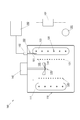
- FIG. 1 is a diagram for explaining a configuration of a beer cooling device to which a freeze detection device according to the present invention is applied.
- a beer cooling device 100 to which a freeze detection device according to the present invention is applied includes a liquid tank 110, an ice making pipe 120, a beverage cooling pipe 130, a cooling liquid stirring unit 140, and a temperature detection unit 150. And a control unit 160.
- the liquid tank 110 is a container for storing a cooling liquid (in this embodiment, water) 111 for cooling beer that is a beverage to be cooled.
- a cooling liquid in this embodiment, water
- the cooling liquid 111 is a target for freezing detection of the freezing detection device according to the present invention.
- the ice making pipe 120 is disposed in the liquid tank 110 and cools the cooling liquid 111 contained in the liquid tank 110 (cooling unit), and has a shape in which the pipe is formed in a coil (spiral) shape. And a refrigerant (for example, chlorofluorocarbon) passes through the inside of the pipe.
- a refrigerant for example, chlorofluorocarbon
- FIG. 1 and the like only the cross section of the ice making pipe 120 is shown for simplicity.
- the ice making pipe 120 constitutes an evaporator in the compression refrigerator, and is connected to the compressor 101, the condenser 102, etc., and constitutes a refrigeration cycle.
- the refrigerant introduced into the ice making pipe 120 through one end of the ice making pipe 120 by the operation of the compressor 101 passes through the ice making pipe 120.
- the ice is evaporated in the ice making pipe 120, and the cooling liquid 111 in the liquid tank 110 is cooled by the endothermic action accompanying the evaporation.
- the cooling liquid around the ice making pipe 120 is frozen, and ice (the cooling liquid is frozen to be in a solid state) is formed around the ice making pipe 120. It will be.
- the refrigerant discharged through the other end of the ice making pipe 120 (in this embodiment, the end 122 disposed below) is returned to the compressor 101.
- the beverage cooling pipe 130 is disposed in the liquid tank 110 and forms a beverage path for allowing a beverage (beer in this embodiment) to flow in the liquid tank 110 (beverage path forming unit).
- a beverage beer in this embodiment
- the beverage cooling pipe 130 has a shape in which the pipe is formed in a coil (spiral) shape, and beer passes through the inside of the pipe.
- FIG. 1 etc. only the cross section is shown like the ice making pipe 120 for the sake of simplicity.
- the beverage cooling pipe 130 is formed so as to form a coil having a smaller diameter than the ice making pipe 120, and is disposed inside the coil formed by the ice making pipe 120.
- Beer introduced into the beverage cooling pipe 130 from the outside (for example, a beer barrel) through one end of the beverage cooling pipe 130 (in this embodiment, the end 131 disposed below) While passing through the cooling pipe 130, it is cooled to a predetermined temperature (for example, 5 ° C.) by the cooling liquid 111 in the liquid tank 110, and is disposed at the other end (in the present embodiment, upward).
- Lead-out end 132 to the outside (for example, a pouring cock).
- the coolant agitator 140 agitates the coolant 111 contained in the liquid tank 110 (agitator) so that the coolant 111 is uniformly cooled.
- the coolant agitator 140 includes a stirring fin 141 and a stirring motor 142. It is configured.
- the stirring fin 141 is disposed in the liquid tank 110 and stirs the cooling liquid 111 accommodated in the liquid tank 110.
- the stirring motor 142 is connected to the stirring fin 141 to drive and rotate the stirring fin 141.
- the stirring fin 141 is disposed inside the cylinder formed by the beverage cooling pipe 130, and when the stirring fin 141 rotates, a downward flow of the cooling liquid is generated in the cylinder formed by the beverage cooling pipe 130. .
- the downward flow of the cooling liquid is directed outward when it hits the bottom surface of the liquid tank 110, and is further directed upward when it hits the inner peripheral surface of the liquid tank 110. That is, when the stirring fin 141 rotates, a flow of the cooling liquid is generated in a downward direction inside the cylinder formed by the beverage cooling pipe 130 and an upward flow in the outside of the cylinder formed by the beverage cooling pipe 130. By forming such a flow of the cooling liquid, the temperature of the cooling liquid 111 in the liquid tank 110 is made uniform.
- the temperature detection unit 150 together with the control unit 160, constitutes a freezing detection device according to the present invention, and is disposed in the vicinity of the ice making pipe 120.
- the temperature detection unit 150 includes a detection unit 151 and an attachment unit 152.
- the detection unit 151 has a tip portion (temperature detection portion) disposed in the vicinity of the ice making pipe 120 and detects the temperature around the tip portion.
- the detection unit 151 has a thermistor (in this embodiment, an NTC thermistor) disposed in the inside (tip portion) of a cylindrical stainless steel case.
- the attachment part 152 is for fixing the detection part 151 so that the front-end
- the temperature detection unit 150 is attached to the liquid tank 110 so that the tip of the detection unit 151 is disposed at a position corresponding to a desired amount of ice.
- the control unit 160 controls the operation of the beer cooling apparatus 100, and in the present embodiment, the function is basically realized by a microprocessor. Further, as described above, the control unit 160 and the temperature detection unit 150 constitute a freeze detection device according to the present invention. That is, based on the output from the temperature detection unit 150, the control unit 160 determines whether or not the liquid to be detected for freezing (the cooling liquid 111 in the present embodiment) is frozen around the temperature detection unit 150. A discrimination unit for discrimination is configured.
- FIG. 2 is a view showing a state in which ice is formed around the ice making pipe 120. The figure shows a state in which a desired amount of ice has been formed.
- the tip portion of the temperature detector 150 is buried in the ice 123. That is, the temperature detection unit 150 is disposed at a position where the tip portion (temperature detection portion) is buried in the ice 123 when a desired amount of ice 123 is formed around the ice making pipe 120. become.
- the control unit 160 starts the operation of the compressor 101.
- the compressor 101 starts its operation, the refrigerant introduced into the ice making pipe 120 evaporates via the condenser 102 and an expansion valve (not shown), thereby cooling the cooling liquid 111 contained in the liquid tank 110. Is done. Then, if the operation of the compressor 101 is continued as it is and the cooling liquid 111 accommodated in the liquid tank 110 is continuously cooled, eventually, ice starts to be formed around the ice making pipe 120. Further, if the operation of the compressor 101 is continued as it is and the cooling liquid 111 accommodated in the liquid tank 110 is continuously cooled, the ice formed around the ice making pipe 120 grows, and eventually the temperature is increased. As shown in FIG. 2, the tip of the temperature detector 150 reaches the tip of the detector 150, and the tip of the temperature detector 150 is buried in the ice 123.
- the control unit 160 that constitutes the freezing detection device together with the temperature detection unit 150 appropriately detects that the temperature of the coolant 111 has decreased to a predetermined temperature (for example, the freezing temperature)
- a predetermined temperature for example, the freezing temperature
- an output signal from the temperature detection unit 150 is output.
- monitoring is started as to whether or not the tip of the temperature detector 150 is buried in ice.
- the operation of the compressor 101 is stopped. Then, this time, based on the output signal from the temperature detection unit 150, whether or not the ice formed around the ice making pipe 120 has melted and the tip of the temperature detection unit 150 is exposed from the ice, Monitor as appropriate.
- the control unit 160 performs on / off control of the compressor 101 so that the amount of ice is maintained after a predetermined amount of ice is formed around the ice making pipe 120. Do.
- the beer When beer is introduced into the beverage cooling pipe 130 via one end 131 of the beverage cooling pipe 130 in a state where a predetermined amount of ice 123 is formed around the ice making pipe 120, the beer Is cooled to a desired temperature (for example, 5 ° C.) by the cooling liquid 111 in the liquid tank 110 while passing through the beverage cooling pipe 130, and the other end 132 of the beverage cooling pipe 130 is cooled. Will come out of.
- a desired temperature for example, 5 ° C.
- FIG. 3 is a diagram showing a state of temperature change detected by the temperature detector 150.
- the horizontal axis represents time (t) and the vertical axis represents temperature (T).
- FIG. 5A shows a state where ice is formed around the ice making pipe 120 but does not reach the periphery of the tip portion of the temperature detection unit 150
- FIG. 2 a state is shown in which the ice formed around the ice making pipe 120 grows and reaches the periphery of the tip portion of the temperature detection unit 150.
- the tip of the temperature detector 150 (the portion where the NTC thermistor is disposed) is the coolant. 111.
- the cooling liquid 111 in the liquid tank 110 is stirred by the cooling liquid stirring unit 140, the flow of the cooling liquid 111 is generated in the liquid tank 110. That is, the flow of the coolant 111 always hits the tip of the temperature detection unit 150.
- the cooling liquid 111 in the liquid tank 110 is sequentially cooled from the periphery of the ice making pipe 120, a certain temperature difference occurs depending on the position in the liquid tank 110.
- a certain temperature difference also occurs in the coolant that hits the tip portion of the temperature detector 150 due to the stirring by the coolant agitator 140.
- the temperature detected by the temperature detector 150 is also shown in FIG. As shown in (), it fluctuates within a certain range with the passage of time.
- the cooling liquid 111 is cooled by the ice making pipe 120, and the ice formed on the surface of the ice making pipe 120 grows, reaches the periphery of the tip portion of the temperature detection unit 150, and the tip portion of the temperature detection unit 150 Is buried in ice, the flow of the coolant does not hit the tip of the temperature detector 150. Then, the temperature detected by the temperature detection unit 150 does not change with time as shown in FIG.
- the freeze detection device determines the difference in temperature change detected by the temperature detection unit 150 and determines whether the tip of the temperature detection unit 150 is buried in ice, that is, It is determined whether or not the coolant is frozen around the front end portion of the temperature detection unit 150. That is, when the temperature detected by the temperature detector 150 is fluctuating, the tip of the temperature detector 150 is not buried in ice, that is, ice is formed around the tip of the temperature detector 150. If the temperature detected by the temperature detector 150 has not changed, the tip of the temperature detector 150 is buried in ice, that is, the tip of the temperature detector 150 Judge that ice has formed around.
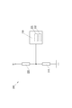
- FIG. 4 is a diagram showing a configuration example of a temperature detection circuit for realizing the freeze detection device according to the present invention.
- the temperature detection circuit 200 includes an NTC thermistor 210 that constitutes the temperature detection unit 150, a resistor 220, and a microprocessor 230 that constitutes the control unit 160.
- One terminal of the NTC thermistor 210 is grounded, and the other terminal is connected to one terminal of the resistor 220 and an analog input terminal of the microprocessor 230.
- the other terminal of the resistor 220 is connected to the power supply voltage V +.
- the voltage value of the signal input to the microprocessor 230 changes. .
- the microprocessor 230 includes an A / D converter 231 inside, and the voltage value (analog data) of the signal input via the analog input terminal is appropriately converted into digital data by the A / D converter 231.
- the microprocessor 230 operates the A / D converter 231 periodically (for example, every 0.1 second) to convert the voltage value of the signal input through the analog input terminal into digital data, and
- the voltage value converted into digital data is converted into a temperature (temperature data) according to a conversion table prepared in advance (sampling).
- the temperature data obtained in this way is sequentially stored by the microprocessor 230 in a temperature data storage area secured in the built-in memory 232 of the microprocessor 230 (or an external memory not shown).
- the temperature data storage area has a size that can store a predetermined amount (for example, 100 pieces) of temperature data over a predetermined period (for example, 10 seconds). Further, the temperature data storage area is managed so as to form a ring buffer, and the temperature data storage area always has a predetermined period after a predetermined period (for example, 10 seconds) has elapsed. The latest temperature data of a predetermined amount (for example, 100 pieces) over (for example, 10 seconds) is stored.
- FIG. 5 is a diagram for explaining the configuration of the temperature data storage area.
- the temperature data storage area 500 is a data storage area having a size capable of storing a predetermined amount (N in the example shown in the figure) of temperature data T 1 to T N.
- the microprocessor 230 when the microprocessor 230 first obtains the temperature data T 1 at the time t 1 by sampling at the time t 1 that is the sampling start time, the microprocessor 230 positions the temperature data T 1 at the head of the temperature data storage area 500. Store in area 501. By sampling at time t 2 is the next sampling time at time t 1, when obtaining the temperature data T 2 at time t 2, and stores the temperature data T 2, in a region 502 following the region 501. Further, the sampling at time t 3, which is the next sampling time of time t 2, the obtains the temperature data T 3 at time t 3, and stores the temperature data T 3, a region 503 following the region 502. The microprocessor 230 repeats such processing at each sampling time.
- the temperature data T N is positioned at the end of the temperature data storage area 500.
- the temperature data storage area 500 stores N pieces of temperature data T 1 to T N over a predetermined period, that is, from time t 1 to time t N as shown in FIG. Become.
- the sampling at time t N + 1 is the next sampling time at time t N, obtains a temperature data T N + 1 at time t N + 1, the microprocessor 230, The temperature data T N + 1 is stored in the area 501 again by returning to the area 501 located at the head. Then, the latest N pieces of temperature data T 2 to T N + 1 from time t 2 to time t N + 1 are stored in the temperature data storage area 500.
- the area 502 is the first area
- the area 501 is the last area via the areas 503 and 511 and the like.
- the sampling at time t N + 2 is the next sampling time at time t N + 1, when obtaining the temperature data T N + 2 at time t N + 2, the temperature data T N + 2, region 501 Is stored in an area 502 subsequent to. Then, the latest N pieces of temperature data T 3 to T N + 2 from time t 3 to time t N + 2 are stored in the temperature data storage area 500.
- the region 503 is the first region
- the region 502 is the last region via the regions 511, 501 and the like.
- the temperature data storage area 500 always stores the latest N pieces of temperature data over a predetermined period. It should be noted that the address of the area that is logically (in time series) the head or the tail is appropriately managed by the microprocessor 230.
- the microprocessor 230 stores the temperature data stored in the temperature data storage area 500.
- T 1 is the oldest temperature stored in the temperature data storage area 500.
- TN becomes the newest temperature data stored in the temperature data storage area 500.
- each time the sampling time comes and new temperature data is stored in the temperature data storage area 500, that is, a predetermined period stored in the temperature data storage area 500 (for example, 10 seconds).
- a predetermined period stored in the temperature data storage area 500 for example, 10 seconds.
- Each time one of the predetermined amount (for example, 100) of temperature data is updated.
- NTC thermistor 210 the tip portion of the temperature detection unit 150 is buried in ice, that is, whether or not a desired amount of ice is formed.
- the tip of the temperature detection unit 150 is changed to ice depending on whether or not the temperature detected by the temperature detection unit 150 varies (within a predetermined period). Since it is determined whether or not it is buried, that is, whether or not a desired amount of ice is formed, it is detected that a desired amount of ice has been formed regardless of the conductivity of the cooling liquid 111. It becomes possible to do. Therefore, for example, even if the conductivity of the cooling liquid in the liquid tank changes with time, it can be determined without error whether or not a desired amount of ice has been formed. In addition, even when an antifreeze that exhibits high conductivity even in a frozen state is used as a coolant, it is possible to determine whether or not a desired amount of ice has been formed.
- the temperature detection unit is configured by an NTC thermistor, but the temperature detection unit is configured by other temperature detection means (for example, a platinum resistance temperature detector or a thermocouple). May be.
- the voltage value converted into digital data is further converted into temperature data.
- the voltage value converted into digital data is used as it is, and the voltage value fluctuates. It may be determined whether or not the tip of the temperature detection unit 150 is buried in ice depending on whether or not it is present.
- the tip portion (temperature detection portion) of the temperature detection unit 150 is disposed in the vicinity of the end portion 121 disposed above the ice making pipe 120. As long as the position corresponds to the amount, it may be arranged at another position, for example, in the vicinity of the end 122 arranged below the ice making pipe 120.
- water is used as the cooling liquid stored in the liquid tank 110, but other liquid (for example, antifreeze liquid) may be used.
Landscapes
- Engineering & Computer Science (AREA)
- Physics & Mathematics (AREA)
- Chemical & Material Sciences (AREA)
- Combustion & Propulsion (AREA)
- Mechanical Engineering (AREA)
- Thermal Sciences (AREA)
- General Engineering & Computer Science (AREA)
- General Physics & Mathematics (AREA)
- Life Sciences & Earth Sciences (AREA)
- Analytical Chemistry (AREA)
- Biochemistry (AREA)
- General Health & Medical Sciences (AREA)
- Health & Medical Sciences (AREA)
- Immunology (AREA)
- Pathology (AREA)
- Devices That Are Associated With Refrigeration Equipment (AREA)
- Investigating Or Analyzing Materials Using Thermal Means (AREA)
- Devices For Dispensing Beverages (AREA)
Description
本発明は、飲料(例えば、ビール)を冷却する飲料冷却装置等に適用される凍結検出装置に関する。
従来、飲食店等において、ビールサーバーを用いて、ビールをジョッキやグラスに注いで客に提供する場合、ビールの冷却には、氷蓄熱式の冷却装置が一般に利用されている。氷蓄熱式の冷却装置は、例えば、冷却装置内に設けられた水槽内に収容された水(飲料冷却液)を、水槽内に配置した圧縮式冷凍機の蒸発器で冷却して、蒸発器の周囲に氷を形成させることで蓄熱を行うと共に、当該水槽内に、ビールを通過させる配管を設けておいて、当該配管内を、ビール樽から導かれるビールを通過させることで、ビールを飲み頃の温度(例えば、5℃程度)まで冷却している。氷による蓄熱を利用することにより、圧縮式冷凍機の小容量化を図りつつ、必要な飲料冷却能力を確保することが可能となる。
このような氷蓄熱式の冷却装置においては、蒸発器の周囲に形成される氷の量が所定の量になるように制御するため、蒸発器の周囲に形成された氷の量が所定の量に達したことを検出するための凍結検出装置を備えている。従来の凍結検出装置では、所望の氷量に対応する位置に一対の電極を設けておいて、水のときと氷になったときとの導電率の差によって、電極部分の周辺が凍結しているか否かを判別することで、所望の量の氷が形成されたか否かを判別していた。
しかしながら、このような従来の凍結検出装置では、時間の経過と共に、水槽内の水の水質が変化して、水槽内の水に含まれる電解質の量が減ってしまった場合、水槽内の水自体の導電率が低くなったことに起因して、所望の量の氷が形成されていないにもかかわらず、所望の量の氷が形成されたと誤った判断をしてしまうことがあった。
また、飲料の種類によっては、従来の氷蓄熱式の冷却装置で冷却可能な温度より低い温度(例えば、-2℃程度)が飲み頃のものも存在する。このような飲料を飲み頃の温度まで冷却する装置としては、飲料冷却液として、水の代わりに、水より低い温度で凍結する不凍液を利用して、当該不凍液を圧縮式冷凍機で冷却することで、従来の氷蓄熱式の冷却装置より低い温度までの飲料の冷却を実現するものが知られている。
このように不凍液を飲料冷却液として使用した場合は、通常、不凍液の導電率は水と比較して高いため、凍結した状態においても高い導電率を示すこととなり、導電率の違いによって、凍っているか否かを判別することは困難であった。
なお、特開2011-73775号公報には、水槽の蒸発管の近傍に配置され、蒸発管の周りに所定の厚さの氷が形成されているか否かを水の電気抵抗(導電率)の変化で検知する氷着センサを備えたビールサーバ、及び、蒸発管の周りに所定の厚さの氷が形成されているか否かを、冷却水と氷との温度差を利用して検知する氷着検出用温度センサを備えたビールサーバが記載されている。
本発明の目的は、凍結検出対象となる液体の導電率にかかわらず、凍結検出対象となる液体が凍結しているか否かを判別可能な凍結検出装置を提供することにある。
本発明に係る凍結検出装置は、凍結検出対象となる液体を収容する液槽と、当該液槽内に配置されて、前記液体を冷却する冷却部とを備えた液体冷却装置に適用される凍結検出装置であって、前記冷却部から所定の距離に配置される温度検知部と、前記温度検知部からの出力に基づいて、前記温度検知部の周辺において前記液体が凍結しているか否かを判別する判別部とを備え、前記判別部は、前記温度検知部からの出力が変動しているか否かに基づいて、前記温度検知部の周辺において前記液体が凍結しているか否かを判別することを特徴とする。
この場合において、前記判別部は、前記温度検知部からの出力が変動している場合は、前記温度検知部の周辺において前記液体が凍結していないと判断し、前記温度検知部からの出力が変動していない場合は、前記温度検知部の周辺において前記液体が凍結していると判断するようにしてもよい。また、前記判別部は、前記温度検知部によって検知された温度が変動しているか否かに基づいて、前記温度検知部の周辺において前記液体が凍結しているか否かを判別するようにしてもよい。
また、以上の場合において、前記温度検知部は、サーミスタ(例えば、NTCサーミスタ)によって構成するようにしてもよい。
本発明に係る液体冷却装置は、凍結検出対象となる液体を収容する液槽と、当該液槽内に配置されて、前記液体を冷却する冷却部と、上記凍結検出装置とを備えたことを特徴とする。
この場合において、前記液槽に収容された前記液体を攪拌するための攪拌部を更に備えようにしてもよい。また、前記冷却部は、圧縮式冷凍機の蒸発器によって構成されているようにしてもよい。更にこの場合、前記判別部によって、前記温度検知部の周辺において前記液体が凍結していないと判断された場合は、前記圧縮式冷凍機を動作させ、前記温度検知部の周辺において前記液体が凍結していると判断された場合は、前記圧縮式冷凍機を停止させるようにしてもよい。
また、前記液体は、例えば、水であってもよいし、不凍液であってもよい。
本発明に係る飲料冷却装置は、上記液体冷却装置と、冷却対象となる飲料を流すための飲料路を形成する飲料路形成部とを備えた飲料冷却装置であって、前記飲料路形成部は、前記液槽内に配置されていることを特徴とする。
この場合において、前記凍結検出装置は、前記冷却部の周囲に所望の量の氷が形成されているか否かを判別するようにしてもよい。更にこの場合、前記温度検知部は、前記所望の量に対応する位置に配置されているようにしてもよい。
本発明によれば、凍結検出対象となる液体の導電率にかかわらず、凍結検出対象となる液体が凍結しているか否かを判別することが可能となる。
以下、本発明の実施の形態について、図面を参照しつつ詳細に説明する。以下では、飲料としてのビールの冷却を行う飲料冷却装置(以下、ビール冷却装置という)に本発明を適用した場合について説明する。本ビール冷却装置は、外部から供給されるビールを冷却するために利用される。より具体的には、本ビール冷却装置は、外部(例えば、ビール樽)から供給される所定の温度(例えば、25℃)のビールを、所定の飲み頃の温度(例えば、5℃程度)にまで冷却して外部(例えば、注出コック)に供給するものである。
図1は、本発明による凍結検出装置が適用されたビール冷却装置の構成を説明するための図である。
同図に示すように、本発明による凍結検出装置が適用されたビール冷却装置100は、液槽110と、製氷パイプ120と、飲料冷却パイプ130と、冷却液攪拌部140と、温度検知部150と、制御部160とを備える。
液槽110は、冷却対象飲料となるビールを冷却するための冷却液(本実施形態では、水)111を収容するための容器である。本実施形態においては、冷却液111が、本発明による凍結検出装置の凍結検出対象となる。
製氷パイプ120は、液槽110内に配置されて、液槽110に収容された冷却液111を冷却するもの(冷却部)であって、パイプをコイル(螺旋)状に形成したような形状を有し、パイプの内部を冷媒(例えば、フロン)が通過するものである。なお、図1等においては、簡単のため、製氷パイプ120の断面のみを示している。製氷パイプ120は、圧縮式冷凍機における蒸発器を構成するものであり、圧縮機101、凝縮器102等と接続されて、冷凍サイクルを構成する。圧縮機101の動作によって製氷パイプ120の一方の端部(本実施形態では、上方に配置された端部121)を介して、製氷パイプ120内に導入された冷媒は、製氷パイプ120内を通過する際に製氷パイプ120内で蒸発し、当該蒸発に伴う吸熱作用によって、液槽110内の冷却液111が冷却されることとなる。そして、そのまま圧縮機101の動作を継続させると、製氷パイプ120の周囲の冷却液が凍結し、製氷パイプ120の周囲に氷(冷却液が凍結して固体状態になったもの)が形成されることになる。なお、製氷パイプ120の他方の端部(本実施形態では、下方に配置された端部122)を介して排出された冷媒は、圧縮機101に戻される。
飲料冷却パイプ130は、液槽110内に配置されて、液槽110内に飲料(本実施形態ではビール)を流すための飲料路を形成するものであって(飲料路形成部)、飲料冷却パイプ130が液槽110に収容された冷却液111によって冷却されることによって、外部から飲料冷却パイプ130が形成する飲料路に供給されるビールが冷却されることになる。飲料冷却パイプ130は、パイプをコイル(螺旋)状に形成したような形状を有し、パイプの内部をビールが通過する。なお、図1等では、簡単のため、製氷パイプ120同様、断面のみを示している。本実施形態においては、飲料冷却パイプ130は、製氷パイプ120より小径のコイルをなすように形成されており、製氷パイプ120がなすコイルの内側に配置される。外部(例えば、ビール樽)から、飲料冷却パイプ130の一方の端部(本実施形態では、下方に配置された端部131)を介して、飲料冷却パイプ130内に導入されたビールは、飲料冷却パイプ130内を通過する間に、液槽110内の冷却液111によって、所定の温度(例えば、5℃)にまで冷却されて、他方の端部(本実施形態においては、上方に配置された端部132)を介して外部(例えば、注出コック)に導出される。
冷却液攪拌部140は、冷却液111が均一に冷却されるよう、液槽110に収容された冷却液111を攪拌するもの(攪拌部)であって、攪拌フィン141と、攪拌モータ142とによって構成されている。攪拌フィン141は、液槽110内に配置されて、液槽110に収容された冷却液111を攪拌するものである。攪拌モータ142は、攪拌フィン141と接続されて、攪拌フィン141を駆動して、回転させるものである。本実施形態においては、攪拌フィン141は飲料冷却パイプ130がなす円筒の内側に配置されており、攪拌フィン141が回転すると、飲料冷却パイプ130がなす円筒内において、下向きの冷却液の流れが生じる。下向きの冷却液の流れは、液槽110の底面にぶつかると、今度は、外側に向かうようになり、更に、液槽110の内周面にぶつかると、今度は、上方に向かうようになる。すなわち、攪拌フィン141が回転すると、飲料冷却パイプ130がなす円筒の内側において、下方に向かい、飲料冷却パイプ130がなす円筒の外側において、上方に向かう冷却液の流れが生じることとなる。このような冷却液の流れを形成することによって、液槽110内における冷却液111の温度の均一化が促進されることになる。
温度検知部150は、制御部160と共に、本発明による凍結検出装置を構成するものであって、製氷パイプ120の近傍に配置される。温度検知部150は、検知部151と、取付部152とを備える。検知部151は、その先端部分(温度検知部分)が、製氷パイプ120の近傍に配置され、先端部分周辺の温度を検知するものである。本実施形態においては、検知部151は、筒状のステンレス製ケースの内部(先端部分)に、サーミスタ(本実施形態においては、NTCサーミスタ)を配置したものである。取付部152は、検知部151の先端部分が所定の位置に配置されるように、検知部151を固定するためのものである。温度検知部150は、検知部151の先端部分が、所望の氷の量に対応する位置に配置されるように、液槽110に取り付けられる。
制御部160は、ビール冷却装置100の動作の制御を行うものであり、本実施形態においては、その機能は、基本的に、マイクロプロセッサによって実現される。また、前述したように、制御部160は、温度検知部150と共に、本発明による凍結検出装置を構成する。すなわち、制御部160は、温度検知部150からの出力に基づいて、温度検知部150の周辺において凍結検出対象となる液体(本実施形態においては、冷却液111)が凍結しているか否かを判別する判別部を構成する。
図2は、製氷パイプ120の周囲に氷が形成された状態を示す図である。同図は、所望の量の氷が形成された状態を示す図である。
同図に示すように、製氷パイプ120の周囲に所望の量の氷123が形成された状態においては、温度検知部150の先端部分(NTCサーミスタが配置された部分)の周辺にも氷が形成されて、温度検知部150の先端部分が氷123中に埋没したような状態になる。すなわち、温度検知部150は、製氷パイプ120の周囲に所望の量の氷123が形成された時点で、その先端部分(温度検知部分)が氷123中に埋没するような位置に配置されることになる。
次に、以上のような構成を有するビール冷却装置100の動作について説明する。
ビール冷却装置100の電源が投入されると、制御部160は圧縮機101の動作を開始させる。圧縮機101が動作を開始すると、凝縮器102及び膨脹弁(不図示)を介して、製氷パイプ120内に導入された冷媒が蒸発することによって、液槽110に収容された冷却液111が冷却される。そして、そのまま、圧縮機101の運転を継続し、液槽110に収容された冷却液111を冷却し続けると、やがて、製氷パイプ120の周囲に、氷が形成され始める。そして、更に、そのまま、圧縮機101の運転を継続し、液槽110に収容された冷却液111を冷却し続けると、製氷パイプ120の周囲に形成される氷が成長していき、やがて、温度検知部150の先端部分にまで達し、図2に示すように、温度検知部150の先端部分が氷123の中に埋没するようなる。
温度検知部150と共に凍結検出装置を構成する制御部160は、例えば、冷却液111の温度が所定の温度(例えば、凍結温度)まで低下したことを適宜検出すると、温度検知部150からの出力信号に基づいて、温度検知部150の先端部分が氷の中に埋没したか否かの監視を開始する。そして、温度検知部150の先端部分が氷の中に埋没したこと、すなわち、予め決められた量の氷が形成されたことを検出すると、圧縮機101の動作を停止させる。そして、今度は、温度検知部150からの出力信号に基づいて、製氷パイプ120の周囲に形成された氷が溶けて、温度検知部150の先端部分が氷の中から露出したか否かを、適宜監視する。そして、温度検知部150の先端部分が氷の中から露出したこと、すなわち、製氷パイプ120の周囲に形成されている氷の量が、予め決められた量未満になっていることを検出すると、再度、圧縮機101の動作を開始させる。このようにして、制御部160は、製氷パイプ120の周囲に予め決められた量の氷が形成された後は、当該氷の量が維持されるように、圧縮機101のオン・オフ制御を行う。
製氷パイプ120の周囲に予め決められた量の氷123が形成された状態において、飲料冷却パイプ130の一方の端部131を介して、飲料冷却パイプ130内にビールが導入されると、当該ビールは、飲料冷却パイプ130内を通過している間に、液槽110内の冷却液111によって、所望の温度(例えば、5℃)にまで冷却されて、飲料冷却パイプ130の他方の端部132から出てくることになる。
次に、本発明による凍結検出装置の動作について説明する。
図3は、温度検知部150によって検知される温度の時間変化の様子を示す図である。同図において、横軸は時間(t)を示し、縦軸は温度(T)を示す。同図(a)は、製氷パイプ120の周囲に氷が形成されてはいるが、温度検知部150の先端部分の周辺にまでは達してない時の様子を示し、同図(b)は、図2に示すように、製氷パイプ120の周囲に形成された氷が成長して、温度検知部150の先端部分の周辺にまで達した時の様子を示している。
製氷パイプ120の周囲に形成された氷が、温度検知部150の先端部分の周囲にまでは達していない時は、温度検知部150の先端部分(NTCサーミスタが配置された部分)は、冷却液111にされられていることになる。前述したように、液槽110内の冷却液111は、冷却液攪拌部140によって攪拌されているので、液槽110内においては、冷却液111の流れが生じている。すなわち、温度検知部150の先端部分には、冷却液111の流れが常時当たっていることになる。一方、液槽110内の冷却液111は、製氷パイプ120の周辺から順次冷却されていくことから、液槽110内の位置によってある程度の温度差が生じることになる。そのため、冷却液攪拌部140による攪拌によって、温度検知部150の先端部分に当たる冷却液にもある程度の温度差が生じることになり、その結果、温度検知部150が検知する温度も、図3(a)に示すように、時間の経過と共にある程度の幅で変動することになる。
一方、製氷パイプ120による冷却液111の冷却が進み、製氷パイプ120の表面に形成された氷が成長していき、温度検知部150の先端部分の周辺に達して、温度検知部150の先端部分が氷内に埋没するようになると、冷却液の流れは、温度検知部150の先端部分に当たらなくなる。そうすると、温度検知部150が検知する温度は、同図(b)に示すように、時間変化しないようになる。
本発明による凍結検出装置は、このような温度検知部150によって検知される温度の時間変化の違いを判別して、温度検知部150の先端部分が氷内に埋没しているか否か、すなわち、温度検知部150の先端部分の周辺において、冷却液が凍結しているか否かを判別する。つまり、温度検知部150によって検知される温度が変動している場合は、温度検知部150の先端部分が氷内に埋没していない、すなわち、温度検知部150の先端部分の周辺に氷が形成されていないと判断し、温度検知部150によって検知される温度が変動していない場合は、温度検知部150の先端部分が氷内に埋没している、すなわち、温度検知部150の先端部分の周辺に氷が形成されていると判断する。
図4は、本発明による凍結検出装置を実現するための温度検知回路の構成例を示す図である。
同図に示すように、温度検知回路200は、温度検知部150を構成するNTCサーミスタ210と、抵抗220と、制御部160を構成するマイクロプロセッサ230とを備える。そして、NTCサーミスタ210の一方の端子は接地され、他方の端子は、抵抗220の一方の端子及びマイクロプロセッサ230のアナログ入力端子に接続される。また、抵抗220の他方の端子は、電源電圧V+に接続される。
同図に示したような温度検知回路200においては、周辺の温度の変化に応じて、NTCサーミスタ210の抵抗値が変化すると、マイクロプロセッサ230に入力される信号の電圧値が変化することになる。
マイクロプロセッサ230は、内部にA/D変換器231を備えており、アナログ入力端子を介して入力された信号の電圧値(アナログデータ)は、A/D変換器231によって適宜デジタルデータに変換される。マイクロプロセッサ230は、定期的(例えば、0.1秒ごと)に、A/D変換器231を動作させて、アナログ入力端子を介して入力される信号の電圧値をデジタルデータに変換し、更に、デジタルデータに変換された電圧値を、予め用意された変換表に従って、温度(温度データ)に変換する(サンプリング)。このようにして得られた温度データは、マイクロプロセッサ230によって、マイクロプロセッサ230の内蔵メモリ232(あるいは不図示の外部メモリ)に確保された温度データ格納領域に順次格納される。温度データ格納領域は、予め決められた期間(例えば、10秒間)にわたる予め決められた量(例えば、100個分)の温度データを格納できるようなサイズが確保されている。また、温度データ格納領域は、リングバッファをなすように管理されており、温度データ格納領域には、予め決められた期間(例えば、10秒間)が経過した後は、常時、予め決められた期間(例えば、10秒間)にわたる予め決められた量(例えば、100個分)の最新の温度データが格納されているようになる。
図5は、温度データ格納領域の構成を説明するための図である。
同図に示すように、温度データ格納領域500は、予め決められた量(同図に示した例ではN個)の温度データT1~TNを格納できるサイズを有するデータ格納領域である。
例えば、マイクロプロセッサ230は、まず、サンプリング開始時刻である時刻t1におけるサンプリングにより、時刻t1における温度データT1を得ると、当該温度データT1を、温度データ格納領域500の先頭に位置する領域501に格納する。そして、時刻t1の次のサンプリング時刻である時刻t2におけるサンプリングにより、時刻t2における温度データT2を得ると、当該温度データT2を、領域501に続く領域502に格納する。更に、時刻t2の次のサンプリング時刻である時刻t3におけるサンプリングにより、時刻t3における温度データT3を得ると、当該温度データT3を、領域502に続く領域503に格納する。マイクロプロセッサ230は、このような処理を各サンプリング時刻において繰り返す。そして、サンプリング開始時刻から予め決められた期間が経過した時刻tNにおけるサンプリングにより、N個目の温度データTNを得ると、当該温度データTNを、温度データ格納領域500の最後尾に位置する領域511に格納する。その結果、温度データ格納領域500には、同図に示すように、予め決められた期間、すなわち、時刻t1~時刻tNにわたるN個の温度データT1~TNが格納されることになる。
同図に示した状態から、更に、時刻tNの次のサンプリング時刻である時刻tN+1におけるサンプリングにより、時刻tN+1における温度データTN+1を得ると、マイクロプロセッサ230は、再度、先頭に位置する領域501に戻って、当該温度データTN+1を、領域501に格納する。そうすると、温度データ格納領域500には、時刻t2~時刻tN+1にわたる最新のN個の温度データT2~TN+1が格納されることになる。なお、この場合、論理的(時系列的)には、領域502が先頭の領域となり、領域503,511等を介して、領域501が最後尾の領域となる。更に、時刻tN+1の次のサンプリング時刻である時刻tN+2におけるサンプリングにより、時刻tN+2における温度データTN+2を得ると、当該温度データTN+2を、領域501に続く領域502に格納する。そうすると、温度データ格納領域500には、時刻t3~時刻tN+2にわたる最新のN個の温度データT3~TN+2が格納されることになる。なお、この場合、論理的(時系列的)には、領域503が先頭の領域となり、領域511,501等を介して、領域502が最後尾の領域となる。このような処理を各サンプリング時刻において繰り返すことにより、温度データ格納領域500には、常時、予め決められた期間にわたる最新のN個の温度データが格納されているようになる。なお、論理的(時系列的)に先頭や最後尾となる領域のアドレスは、適宜マイクロプロセッサ230によって管理される。
予め決められた期間(例えば、10秒間)にわたる予め決められた量(例えば、100個分)の温度データの収集が完了すると、マイクロプロセッサ230は、温度データ格納領域500に格納されている温度データに対して、適宜フィルタ処理を行って、ノイズを除去した後に、温度データ格納領域500に格納されている温度データが時間経過と共に変動しているか否かを判別する。例えば、時間的に隣接する温度データの差の絶対値を順次加算していき、その総和を算出する。すなわち、次の式1で示される総和Sを算出する。

ここで、Ti(i=1~N)は、温度データ格納領域500に格納されている各温度データであって、ここでは、T1が温度データ格納領域500に格納されている最も古い温度データになり、TNが温度データ格納領域500に格納されている最も新しい温度データになる。
そして、以上のようにして算出された総和Sが所定の閾値以上になっているか否かを判別して、総和Sが所定の閾値以上になっていれば、温度は時間と共に変動している(すなわち、NTCサーミスタ210は、氷に埋没していない)と判断し、総和Sが所定の閾値未満であれば、(予め決められた期間内において)温度は変動していない(すなわち、NTCサーミスタ210は、氷に埋没している)と判断する。なお、温度データ格納領域500に格納されている温度データが時間経過と共に変動しているか否かの判別は、温度の変動周期、サンプリング周期、マイクロプロセッサ230の処理速度等の実装条件に応じて適当なタイミングで行われる。本実施形態においては、各サンプリング時刻が到来し、温度データ格納領域500に新たな温度データを格納する度、すなわち、温度データ格納領域500に格納されている予め決められた期間(例えば、10秒間)にわたる予め決められた量(例えば、100個分)の温度データのうちの一つが更新される毎に行う。
以上のようにして、温度検知部150の先端部分(NTCサーミスタ210)が氷に埋没しているか否か、すなわち、所望の量の氷が形成されているか否かが判別されることとなる。
以上説明したように、上述した凍結検出装置においては、温度検知部150が検知する温度が(予め決められた期間内において)変動しているか否かによって、温度検知部150の先端部分が氷に埋没しているか否か、すなわち、所望の量の氷が形成されているか否かを判別しているので、冷却液111の導電率にかかわらず、所望の量の氷が形成されたことを検出することが可能となる。従って、例えば、時間の経過と共に、液槽内の冷却液の導電率が変化したとしても、所望の量の氷が形成されたか否かを誤りなく判別することができる。また、凍結した状態においても高い導電率を示す不凍液を冷却液として使用した場合であっても、所望の量の氷が形成されたか否かを判別することができるようになる。
以上、本発明の実施形態について説明してきたが、当然のことながら、本発明の実施形態は上記のものに限られない。例えば、上述した実施形態においては、温度検知部をNTCサーミスタで構成するようにしていたが、温度検知部を他の温度検知手段(例えば、白金測温抵抗体や熱電対)で構成するようにしてもよい。
また、上述した実施形態においては、デジタルデータに変換された電圧値を更に温度データに変換するようにしていたが、デジタルデータに変換された電圧値をそのまま使用して、当該電圧値が変動しているか否かによって、温度検知部150の先端部分が氷内に埋没しているか否かを判別するようしてもよい。
また、上述した実施形態においては、温度検知部150の先端部分(温度検知部分)を、製氷パイプ120の上方に配置された端部121の近傍に配置するようにしていたが、所望の氷の量に対応する位置であれば他の位置、例えば、製氷パイプ120の下方に配置された端部122の近傍に配置するようにしてもよい。
また、上述した実施形態においては、液槽110内に収容する冷却液として、水を使用していたが、他の液体(例えば、不凍液)を使用するようしてもよい。
100 ビール冷却装置
101 圧縮機
102 凝縮器
110 液槽
111 冷却液
120 製氷パイプ
121,122 端部
123 氷
130 飲料冷却パイプ
131,132 端部
140 冷却液攪拌部
141 攪拌フィン
142 攪拌モータ
150 温度検知部
151 検知部
152 取付部
160 制御部
200 温度検知回路
210 NTCサーミスタ
220 抵抗
230 マイクロプロセッサ
231 A/D変換器
232 内蔵メモリ
500 温度データ格納領域
501,502,503,511 領域
101 圧縮機
102 凝縮器
110 液槽
111 冷却液
120 製氷パイプ
121,122 端部
123 氷
130 飲料冷却パイプ
131,132 端部
140 冷却液攪拌部
141 攪拌フィン
142 攪拌モータ
150 温度検知部
151 検知部
152 取付部
160 制御部
200 温度検知回路
210 NTCサーミスタ
220 抵抗
230 マイクロプロセッサ
231 A/D変換器
232 内蔵メモリ
500 温度データ格納領域
501,502,503,511 領域
Claims (12)
- 凍結検出対象となる液体を収容する液槽と、当該液槽内に配置されて、前記液体を冷却する冷却部とを備えた液体冷却装置に適用される凍結検出装置であって、
前記冷却部から所定の距離に配置される温度検知部と、
前記温度検知部からの出力に基づいて、前記温度検知部の周辺において前記液体が凍結しているか否かを判別する判別部と
を備え、
前記判別部は、前記温度検知部からの出力が変動しているか否かに基づいて、前記温度検知部の周辺において前記液体が凍結しているか否かを判別する
ことを特徴とする凍結検出装置。 - 前記判別部は、前記温度検知部からの出力が変動している場合は、前記温度検知部の周辺において前記液体が凍結していないと判断し、前記温度検知部からの出力が変動していない場合は、前記温度検知部の周辺において前記液体が凍結していると判断する
ことを特徴とする請求項1に記載の凍結検出装置。 - 前記判別部は、前記温度検知部によって検知された温度が変動しているか否かに基づいて、前記温度検知部の周辺において前記液体が凍結しているか否かを判別する
ことを特徴とする請求項1又は2に記載の凍結検出装置。 - 前記温度検知部は、サーミスタによって構成されている
ことを特徴とする請求項1~3のいずれか一項に記載の凍結検出装置。 - 凍結検出対象となる液体を収容する液槽と、
前記液槽内に配置されて、前記液体を冷却する冷却部と、
請求項1~4のいずれか一項に記載の凍結検出装置と
を備えたことを特徴とする液体冷却装置。 - 前記液槽に収容された前記液体を攪拌するための攪拌部
を更に備えたことを特徴とする請求項5に記載の液体冷却装置。 - 前記冷却部は、圧縮式冷凍機の蒸発器によって構成されている
ことを特徴とする請求項5又は6に記載の液体冷却装置。 - 前記判別部によって、前記温度検知部の周辺において前記液体が凍結していないと判断された場合は、前記圧縮式冷凍機を動作させ、前記温度検知部の周辺において前記液体が凍結していると判断された場合は、前記圧縮式冷凍機を停止させる
ことを特徴する請求項7に記載の液体冷却装置。 - 前記液体は、不凍液である
ことを特徴とする請求項5~8のいずれか一項に記載の液体冷却装置。 - 請求項5~9のいずれか一項に記載の液体冷却装置と、
冷却対象となる飲料を流すための飲料路を形成する飲料路形成部と
を備えた飲料冷却装置であって、
前記飲料路形成部は、前記液槽内に配置されている
ことを特徴とする飲料冷却装置。 - 前記凍結検出装置は、前記冷却部の周囲に所望の量の氷が形成されているか否かを判別する
ことを特徴とする請求項10に記載の飲料冷却装置。 - 前記温度検知部は、前記所望の量に対応する位置に配置されている
ことを特徴とする請求項11に記載の飲料冷却装置。
Priority Applications (2)
| Application Number | Priority Date | Filing Date | Title |
|---|---|---|---|
| EP13738758.5A EP2806265B1 (en) | 2012-01-17 | 2013-01-10 | Freezing detection device |
| US14/333,389 US9897367B2 (en) | 2012-01-17 | 2014-07-16 | Freezing detection device |
Applications Claiming Priority (2)
| Application Number | Priority Date | Filing Date | Title |
|---|---|---|---|
| JP2012-007506 | 2012-01-17 | ||
| JP2012007506A JP5945378B2 (ja) | 2012-01-17 | 2012-01-17 | 凍結検出装置 |
Related Child Applications (1)
| Application Number | Title | Priority Date | Filing Date |
|---|---|---|---|
| US14/333,389 Continuation US9897367B2 (en) | 2012-01-17 | 2014-07-16 | Freezing detection device |
Publications (1)
| Publication Number | Publication Date |
|---|---|
| WO2013108702A1 true WO2013108702A1 (ja) | 2013-07-25 |
Family
ID=48799128
Family Applications (1)
| Application Number | Title | Priority Date | Filing Date |
|---|---|---|---|
| PCT/JP2013/050276 Ceased WO2013108702A1 (ja) | 2012-01-17 | 2013-01-10 | 凍結検出装置 |
Country Status (4)
| Country | Link |
|---|---|
| US (1) | US9897367B2 (ja) |
| EP (1) | EP2806265B1 (ja) |
| JP (1) | JP5945378B2 (ja) |
| WO (1) | WO2013108702A1 (ja) |
Cited By (3)
| Publication number | Priority date | Publication date | Assignee | Title |
|---|---|---|---|---|
| US20210251418A1 (en) * | 2015-11-13 | 2021-08-19 | IceColdNow, Inc. | Coldwave appliance |
| JP2022520782A (ja) * | 2019-02-12 | 2022-04-01 | カールスバーグ ブルワリーズ アグシャセルスガーブ | 飲料分配システムの監視 |
| JP2024174937A (ja) * | 2019-05-17 | 2024-12-17 | ペプシコ・インク | 水分配ステーション |
Families Citing this family (4)
| Publication number | Priority date | Publication date | Assignee | Title |
|---|---|---|---|---|
| CN105180551B (zh) * | 2014-05-30 | 2017-11-28 | 青岛海尔特种电冰柜有限公司 | 一种罐/瓶体饮品的冷藏方法 |
| CN105202861B (zh) * | 2014-05-30 | 2017-11-28 | 青岛海尔特种电冰柜有限公司 | 一种罐/瓶体饮品速冷机的速冷方法 |
| CN108593702A (zh) * | 2017-03-15 | 2018-09-28 | 中山大学 | 适用观察低温固液相变的可视化测试装置及其使用方法 |
| CN112649584A (zh) * | 2020-12-18 | 2021-04-13 | 联想(北京)有限公司 | 一种液体的状态检测方法及设备 |
Citations (7)
| Publication number | Priority date | Publication date | Assignee | Title |
|---|---|---|---|---|
| JPS5658650A (en) * | 1979-10-19 | 1981-05-21 | Tsuruga Denki Seisakusho:Kk | Detecting device for freezing |
| JPS5757809A (en) * | 1980-09-26 | 1982-04-07 | Kawasaki Steel Corp | Detection of hanging product on wall of blast furnace |
| JPH0989546A (ja) * | 1995-09-28 | 1997-04-04 | Mitsubishi Materials Corp | 氷厚測定装置 |
| JPH1151531A (ja) * | 1997-07-30 | 1999-02-26 | Ooizumi Seisakusho:Kk | 製氷検知器 |
| JP2004116814A (ja) * | 2002-09-24 | 2004-04-15 | Ishikawajima Harima Heavy Ind Co Ltd | 過冷却水製造装置の制御方法及び装置 |
| JP2011073775A (ja) | 2009-10-01 | 2011-04-14 | Asahi Breweries Ltd | 液体供給装置及び稼働状況管理装置 |
| JP2011122793A (ja) * | 2009-12-14 | 2011-06-23 | Asahi Breweries Ltd | 液体供給装置及び冷却水状態判断装置 |
Family Cites Families (13)
| Publication number | Priority date | Publication date | Assignee | Title |
|---|---|---|---|---|
| US2494512A (en) * | 1946-06-11 | 1950-01-10 | Revco Inc | Milk cooler having automatic control means |
| US3882693A (en) * | 1974-02-01 | 1975-05-13 | Rayne International | Water cooler |
| JPS5559302A (en) * | 1978-10-30 | 1980-05-02 | Mayekawa Mfg Co Ltd | Freezing thickness detector |
| US4662184A (en) * | 1986-01-06 | 1987-05-05 | General Electric Company | Single-sensor head pump defrost control system |
| US5022233A (en) * | 1987-11-02 | 1991-06-11 | The Coca-Cola Company | Ice bank control system for beverage dispenser |
| US4907417A (en) * | 1988-03-21 | 1990-03-13 | Emerson Electric Co. | Refrigeration control system for cold drink dispenser |
| US4932222A (en) * | 1988-10-18 | 1990-06-12 | Adams Jr Thomas A | In-line milk cooler |
| US5839291A (en) * | 1996-08-14 | 1998-11-24 | Multiplex Company, Inc. | Beverage cooling and dispensing system with diagnostics |
| JP3852630B2 (ja) * | 1997-03-11 | 2006-12-06 | オリオン機械株式会社 | 蓄氷式冷水製造装置 |
| US5987897A (en) * | 1997-05-30 | 1999-11-23 | Ranco Incorporated Of Delaware | Ice bank system |
| US6581391B2 (en) * | 2000-05-01 | 2003-06-24 | Technology Licensing Corporation | Ice thickness control system and sensor probe |
| CA2448893A1 (en) * | 2003-11-12 | 2005-05-12 | Icefloe Technologies Inc. | Method and apparatus for controlled ice crystal formation in a beverage |
| KR100982701B1 (ko) * | 2007-04-24 | 2010-09-17 | 웅진코웨이주식회사 | 수처리 장치 |
-
2012
- 2012-01-17 JP JP2012007506A patent/JP5945378B2/ja active Active
-
2013
- 2013-01-10 EP EP13738758.5A patent/EP2806265B1/en not_active Not-in-force
- 2013-01-10 WO PCT/JP2013/050276 patent/WO2013108702A1/ja not_active Ceased
-
2014
- 2014-07-16 US US14/333,389 patent/US9897367B2/en not_active Expired - Fee Related
Patent Citations (7)
| Publication number | Priority date | Publication date | Assignee | Title |
|---|---|---|---|---|
| JPS5658650A (en) * | 1979-10-19 | 1981-05-21 | Tsuruga Denki Seisakusho:Kk | Detecting device for freezing |
| JPS5757809A (en) * | 1980-09-26 | 1982-04-07 | Kawasaki Steel Corp | Detection of hanging product on wall of blast furnace |
| JPH0989546A (ja) * | 1995-09-28 | 1997-04-04 | Mitsubishi Materials Corp | 氷厚測定装置 |
| JPH1151531A (ja) * | 1997-07-30 | 1999-02-26 | Ooizumi Seisakusho:Kk | 製氷検知器 |
| JP2004116814A (ja) * | 2002-09-24 | 2004-04-15 | Ishikawajima Harima Heavy Ind Co Ltd | 過冷却水製造装置の制御方法及び装置 |
| JP2011073775A (ja) | 2009-10-01 | 2011-04-14 | Asahi Breweries Ltd | 液体供給装置及び稼働状況管理装置 |
| JP2011122793A (ja) * | 2009-12-14 | 2011-06-23 | Asahi Breweries Ltd | 液体供給装置及び冷却水状態判断装置 |
Cited By (4)
| Publication number | Priority date | Publication date | Assignee | Title |
|---|---|---|---|---|
| US20210251418A1 (en) * | 2015-11-13 | 2021-08-19 | IceColdNow, Inc. | Coldwave appliance |
| JP2022520782A (ja) * | 2019-02-12 | 2022-04-01 | カールスバーグ ブルワリーズ アグシャセルスガーブ | 飲料分配システムの監視 |
| JP7547351B2 (ja) | 2019-02-12 | 2024-09-09 | カールスバーグ ブルワリーズ アグシャセルスガーブ | 飲料分配システムの監視 |
| JP2024174937A (ja) * | 2019-05-17 | 2024-12-17 | ペプシコ・インク | 水分配ステーション |
Also Published As
| Publication number | Publication date |
|---|---|
| US9897367B2 (en) | 2018-02-20 |
| JP5945378B2 (ja) | 2016-07-05 |
| US20140326009A1 (en) | 2014-11-06 |
| EP2806265A1 (en) | 2014-11-26 |
| EP2806265B1 (en) | 2021-11-17 |
| EP2806265A4 (en) | 2015-12-23 |
| JP2013148399A (ja) | 2013-08-01 |
Similar Documents
| Publication | Publication Date | Title |
|---|---|---|
| JP5945378B2 (ja) | 凍結検出装置 | |
| US11543161B2 (en) | Ice maker with reversing condenser fan motor to maintain clean condenser | |
| US10788250B2 (en) | Ice making assemblies and methods for making clear ice | |
| US20200370812A1 (en) | Ice maker with push notification to indicate when maintenance is required | |
| US11498825B2 (en) | Liquid quality managing device and method | |
| US20020104322A1 (en) | Ice thickness control system and sensor probe | |
| JP6590093B2 (ja) | 製氷システムとこれに用いる蒸発温度の制御方法 | |
| JP2008304155A (ja) | 自動製氷機付き冷蔵庫 | |
| IL269943B1 (en) | Cooling bath for liquid cooling | |
| JP2009162392A (ja) | シャーベット氷生成装置およびシャーベット氷生成方法 | |
| KR20140041009A (ko) | 음용수 냉각장치의 온도조절시스템 | |
| KR20190046179A (ko) | 제빙 기능을 구비한 정수기 및 이의 동작 방법 | |
| JP2017003239A (ja) | 製氷機 | |
| JP5875797B2 (ja) | 飲料冷却装置 | |
| JP3991938B2 (ja) | 自動製氷機 | |
| JP2006329538A (ja) | 飲料水ディスペンサー | |
| JPH06227595A (ja) | 飲料供給装置 | |
| KR101127921B1 (ko) | 얼음 정수기용 제빙용 물받이 탈착 감지방법 | |
| EP3339773B1 (en) | Excitation based ice detection unit, refrigerator with ice detection unit and method for defrosting of a refrigerator | |
| JP2008096021A (ja) | 自動製氷装置付き冷凍冷蔵庫 | |
| JP2012002376A (ja) | 飲料冷却装置 | |
| CN120890224A (zh) | 制冰组件的控制方法、存储介质及制冷设备 | |
| JP2005009824A (ja) | 自動製氷機 | |
| JP2002267302A (ja) | 製氷機 | |
| JP2003192098A (ja) | 冷飲料供給装置 |
Legal Events
| Date | Code | Title | Description |
|---|---|---|---|
| 121 | Ep: the epo has been informed by wipo that ep was designated in this application |
Ref document number: 13738758 Country of ref document: EP Kind code of ref document: A1 |
|
| WWE | Wipo information: entry into national phase |
Ref document number: 2013738758 Country of ref document: EP |
|
| NENP | Non-entry into the national phase |
Ref country code: DE |