WO2013108708A1 - 非水電解質二次電池の製造方法 - Google Patents
非水電解質二次電池の製造方法 Download PDFInfo
- Publication number
- WO2013108708A1 WO2013108708A1 PCT/JP2013/050315 JP2013050315W WO2013108708A1 WO 2013108708 A1 WO2013108708 A1 WO 2013108708A1 JP 2013050315 W JP2013050315 W JP 2013050315W WO 2013108708 A1 WO2013108708 A1 WO 2013108708A1
- Authority
- WO
- WIPO (PCT)
- Prior art keywords
- charging
- secondary battery
- gas
- sealing
- electrolyte secondary
- Prior art date
- Legal status (The legal status is an assumption and is not a legal conclusion. Google has not performed a legal analysis and makes no representation as to the accuracy of the status listed.)
- Ceased
Links
Images



Classifications
-
- H—ELECTRICITY
- H01—ELECTRIC ELEMENTS
- H01M—PROCESSES OR MEANS, e.g. BATTERIES, FOR THE DIRECT CONVERSION OF CHEMICAL ENERGY INTO ELECTRICAL ENERGY
- H01M10/00—Secondary cells; Manufacture thereof
- H01M10/04—Construction or manufacture in general
- H01M10/0436—Small-sized flat cells or batteries for portable equipment
-
- H—ELECTRICITY
- H01—ELECTRIC ELEMENTS
- H01M—PROCESSES OR MEANS, e.g. BATTERIES, FOR THE DIRECT CONVERSION OF CHEMICAL ENERGY INTO ELECTRICAL ENERGY
- H01M10/00—Secondary cells; Manufacture thereof
- H01M10/05—Accumulators with non-aqueous electrolyte
- H01M10/058—Construction or manufacture
-
- H—ELECTRICITY
- H01—ELECTRIC ELEMENTS
- H01M—PROCESSES OR MEANS, e.g. BATTERIES, FOR THE DIRECT CONVERSION OF CHEMICAL ENERGY INTO ELECTRICAL ENERGY
- H01M10/00—Secondary cells; Manufacture thereof
- H01M10/04—Construction or manufacture in general
- H01M10/0472—Vertically superposed cells with vertically disposed plates
-
- H—ELECTRICITY
- H01—ELECTRIC ELEMENTS
- H01M—PROCESSES OR MEANS, e.g. BATTERIES, FOR THE DIRECT CONVERSION OF CHEMICAL ENERGY INTO ELECTRICAL ENERGY
- H01M10/00—Secondary cells; Manufacture thereof
- H01M10/05—Accumulators with non-aqueous electrolyte
-
- H—ELECTRICITY
- H01—ELECTRIC ELEMENTS
- H01M—PROCESSES OR MEANS, e.g. BATTERIES, FOR THE DIRECT CONVERSION OF CHEMICAL ENERGY INTO ELECTRICAL ENERGY
- H01M10/00—Secondary cells; Manufacture thereof
- H01M10/05—Accumulators with non-aqueous electrolyte
- H01M10/052—Li-accumulators
-
- H—ELECTRICITY
- H01—ELECTRIC ELEMENTS
- H01M—PROCESSES OR MEANS, e.g. BATTERIES, FOR THE DIRECT CONVERSION OF CHEMICAL ENERGY INTO ELECTRICAL ENERGY
- H01M10/00—Secondary cells; Manufacture thereof
- H01M10/42—Methods or arrangements for servicing or maintenance of secondary cells or secondary half-cells
- H01M10/44—Methods for charging or discharging
- H01M10/446—Initial charging measures
-
- H—ELECTRICITY
- H01—ELECTRIC ELEMENTS
- H01M—PROCESSES OR MEANS, e.g. BATTERIES, FOR THE DIRECT CONVERSION OF CHEMICAL ENERGY INTO ELECTRICAL ENERGY
- H01M10/00—Secondary cells; Manufacture thereof
- H01M10/42—Methods or arrangements for servicing or maintenance of secondary cells or secondary half-cells
- H01M10/52—Removing gases inside the secondary cell, e.g. by absorption
-
- H—ELECTRICITY
- H01—ELECTRIC ELEMENTS
- H01M—PROCESSES OR MEANS, e.g. BATTERIES, FOR THE DIRECT CONVERSION OF CHEMICAL ENERGY INTO ELECTRICAL ENERGY
- H01M50/00—Constructional details or processes of manufacture of the non-active parts of electrochemical cells other than fuel cells, e.g. hybrid cells
- H01M50/10—Primary casings; Jackets or wrappings
- H01M50/116—Primary casings; Jackets or wrappings characterised by the material
- H01M50/117—Inorganic material
- H01M50/119—Metals
-
- H—ELECTRICITY
- H01—ELECTRIC ELEMENTS
- H01M—PROCESSES OR MEANS, e.g. BATTERIES, FOR THE DIRECT CONVERSION OF CHEMICAL ENERGY INTO ELECTRICAL ENERGY
- H01M50/00—Constructional details or processes of manufacture of the non-active parts of electrochemical cells other than fuel cells, e.g. hybrid cells
- H01M50/10—Primary casings; Jackets or wrappings
- H01M50/116—Primary casings; Jackets or wrappings characterised by the material
- H01M50/121—Organic material
-
- H—ELECTRICITY
- H01—ELECTRIC ELEMENTS
- H01M—PROCESSES OR MEANS, e.g. BATTERIES, FOR THE DIRECT CONVERSION OF CHEMICAL ENERGY INTO ELECTRICAL ENERGY
- H01M50/00—Constructional details or processes of manufacture of the non-active parts of electrochemical cells other than fuel cells, e.g. hybrid cells
- H01M50/10—Primary casings; Jackets or wrappings
- H01M50/116—Primary casings; Jackets or wrappings characterised by the material
- H01M50/124—Primary casings; Jackets or wrappings characterised by the material having a layered structure
- H01M50/126—Primary casings; Jackets or wrappings characterised by the material having a layered structure comprising three or more layers
- H01M50/129—Primary casings; Jackets or wrappings characterised by the material having a layered structure comprising three or more layers with two or more layers of only organic material
-
- H—ELECTRICITY
- H01—ELECTRIC ELEMENTS
- H01M—PROCESSES OR MEANS, e.g. BATTERIES, FOR THE DIRECT CONVERSION OF CHEMICAL ENERGY INTO ELECTRICAL ENERGY
- H01M50/00—Constructional details or processes of manufacture of the non-active parts of electrochemical cells other than fuel cells, e.g. hybrid cells
- H01M50/10—Primary casings; Jackets or wrappings
- H01M50/131—Primary casings; Jackets or wrappings characterised by physical properties, e.g. gas permeability, size or heat resistance
- H01M50/133—Thickness
-
- H—ELECTRICITY
- H01—ELECTRIC ELEMENTS
- H01M—PROCESSES OR MEANS, e.g. BATTERIES, FOR THE DIRECT CONVERSION OF CHEMICAL ENERGY INTO ELECTRICAL ENERGY
- H01M10/00—Secondary cells; Manufacture thereof
- H01M10/05—Accumulators with non-aqueous electrolyte
- H01M10/052—Li-accumulators
- H01M10/0525—Rocking-chair batteries, i.e. batteries with lithium insertion or intercalation in both electrodes; Lithium-ion batteries
-
- H—ELECTRICITY
- H01—ELECTRIC ELEMENTS
- H01M—PROCESSES OR MEANS, e.g. BATTERIES, FOR THE DIRECT CONVERSION OF CHEMICAL ENERGY INTO ELECTRICAL ENERGY
- H01M10/00—Secondary cells; Manufacture thereof
- H01M10/05—Accumulators with non-aqueous electrolyte
- H01M10/058—Construction or manufacture
- H01M10/0585—Construction or manufacture of accumulators having only flat construction elements, i.e. flat positive electrodes, flat negative electrodes and flat separators
-
- H—ELECTRICITY
- H01—ELECTRIC ELEMENTS
- H01M—PROCESSES OR MEANS, e.g. BATTERIES, FOR THE DIRECT CONVERSION OF CHEMICAL ENERGY INTO ELECTRICAL ENERGY
- H01M50/00—Constructional details or processes of manufacture of the non-active parts of electrochemical cells other than fuel cells, e.g. hybrid cells
- H01M50/10—Primary casings; Jackets or wrappings
- H01M50/116—Primary casings; Jackets or wrappings characterised by the material
- H01M50/124—Primary casings; Jackets or wrappings characterised by the material having a layered structure
-
- Y—GENERAL TAGGING OF NEW TECHNOLOGICAL DEVELOPMENTS; GENERAL TAGGING OF CROSS-SECTIONAL TECHNOLOGIES SPANNING OVER SEVERAL SECTIONS OF THE IPC; TECHNICAL SUBJECTS COVERED BY FORMER USPC CROSS-REFERENCE ART COLLECTIONS [XRACs] AND DIGESTS
- Y02—TECHNOLOGIES OR APPLICATIONS FOR MITIGATION OR ADAPTATION AGAINST CLIMATE CHANGE
- Y02E—REDUCTION OF GREENHOUSE GAS [GHG] EMISSIONS, RELATED TO ENERGY GENERATION, TRANSMISSION OR DISTRIBUTION
- Y02E60/00—Enabling technologies; Technologies with a potential or indirect contribution to GHG emissions mitigation
- Y02E60/10—Energy storage using batteries
-
- Y—GENERAL TAGGING OF NEW TECHNOLOGICAL DEVELOPMENTS; GENERAL TAGGING OF CROSS-SECTIONAL TECHNOLOGIES SPANNING OVER SEVERAL SECTIONS OF THE IPC; TECHNICAL SUBJECTS COVERED BY FORMER USPC CROSS-REFERENCE ART COLLECTIONS [XRACs] AND DIGESTS
- Y02—TECHNOLOGIES OR APPLICATIONS FOR MITIGATION OR ADAPTATION AGAINST CLIMATE CHANGE
- Y02P—CLIMATE CHANGE MITIGATION TECHNOLOGIES IN THE PRODUCTION OR PROCESSING OF GOODS
- Y02P70/00—Climate change mitigation technologies in the production process for final industrial or consumer products
- Y02P70/50—Manufacturing or production processes characterised by the final manufactured product
-
- Y—GENERAL TAGGING OF NEW TECHNOLOGICAL DEVELOPMENTS; GENERAL TAGGING OF CROSS-SECTIONAL TECHNOLOGIES SPANNING OVER SEVERAL SECTIONS OF THE IPC; TECHNICAL SUBJECTS COVERED BY FORMER USPC CROSS-REFERENCE ART COLLECTIONS [XRACs] AND DIGESTS
- Y10—TECHNICAL SUBJECTS COVERED BY FORMER USPC
- Y10T—TECHNICAL SUBJECTS COVERED BY FORMER US CLASSIFICATION
- Y10T29/00—Metal working
- Y10T29/49—Method of mechanical manufacture
- Y10T29/49002—Electrical device making
- Y10T29/49108—Electric battery cell making
- Y10T29/4911—Electric battery cell making including sealing
Definitions
- an electrode laminate in which a separator is disposed between a positive electrode and a negative electrode and an electrolyte are housed and sealed in an outer package made of a laminate film, and charging is performed via a terminal of the electrode laminate.
- the present invention relates to a method for producing a nonaqueous electrolyte secondary battery having a charging step.
- Lithium-ion secondary batteries have higher energy density, higher operating voltage, less self-discharge, and superior characteristics compared to conventional secondary batteries such as nickel-metal hydride batteries and lead-acid batteries, such as notebook computers and mobile phones. It has been widely used for small electronic devices, and more recently as a power storage for in-vehicle use and stationary use.
- gas is generated with the reaction of the electrolyte.
- a gas removal step for removing the gas in the exterior body is performed after the charging step. In such a gas removal step, an operation of opening the exterior body is performed.
- Patent Document 1 discloses an electrode stack, a sealing step for sealing a specific filler in an exterior body, a first charging step for charging to less than a fully charged voltage, and a second charging for full charging.
- a method for manufacturing a battery having a charging step is disclosed. According to this manufacturing method, it is unnecessary to open the exterior body in order to remove the gas after the second charging step by performing the gas removing step after the first charging step using a specific filling. Yes.
- Patent Document 1 Although the manufacturing method described in Patent Document 1 described above can reduce the gas removal step performed after the second charging step, there is a problem that the gas generated after the second charging step deteriorates the battery characteristics.
- the battery manufacturing method it is preferable to suppress the influence of gas on the battery characteristics.
- an object of the present invention is to provide a method for manufacturing a non-aqueous electrolyte secondary battery that can solve the above-described problems.
- a method for producing a non-aqueous electrolyte secondary battery according to the present invention includes a sealing process in which an electrode laminate in which a separator is disposed between a positive electrode and a negative electrode, and an electrolyte are housed and sealed in an outer package made of a laminate film. And a pressurizing step for pressurizing the outer package containing the electrode laminate, a charging step for charging until full charge, and a gas removing step for removing the gas generated in the outer package during the charging step by opening the outer package And a reseal step for sealing the outer package after the gas removal step.
- an electrode laminate in which a separator is disposed between a positive electrode and a negative electrode and an electrolyte are stored in an outer package made of a laminate film and sealed under reduced pressure.
- the number of gas removal steps can be reduced, and the influence of gas on battery characteristics can be suppressed.
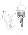
- FIG. 1 shows a cross-sectional view of a non-aqueous electrolyte secondary battery manufactured by the secondary battery manufacturing method of the first embodiment.
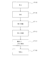
- FIG. 2 is a process procedure diagram for explaining the method for manufacturing the secondary battery according to the first embodiment.
- FIG. 1A shows a perspective view of a nonaqueous electrolyte secondary battery
- FIG. 1B shows a cross-sectional view taken along line AA in FIG.
- a non-aqueous electrolyte secondary battery 1 manufactured by the manufacturing method of the present embodiment is a large-capacity lithium suitable for driving a vehicle on which a non-aqueous electrolyte secondary battery is mounted, for example.
- An ion secondary battery having an electrode size of, for example, 210 mm ⁇ 297 mm or 148 mm ⁇ 210 mm, and a capacity of 4 Ah or more.
- the nonaqueous electrolyte secondary battery 1 manufactured in the present embodiment includes an electrode laminate 5 in which a separator 4 is disposed between a positive electrode 3a and a negative electrode 3b, an electrolytic solution, And an exterior body 6 made of a laminate film 6a for sealing them.
- the outer package 6 may be formed by bending one laminated film 6a and heat-sealing the three surrounding sides, or by overlapping two sheets and heat-sealing the four surrounding sides.
- the thickness of the laminate film 6a is preferably about 100 ⁇ m to 200 ⁇ m, and is a flexible film.
- the negative electrode 3 b, the positive electrode 3 a, and the separator 4 that are the electrodes 3 are formed in a rectangular shape, and the negative electrodes 3 b and the positive electrodes 3 a are alternately stacked via the separator 4. Negative electrodes 3b are respectively disposed at both ends of the electrode stack 5 in the stacking direction.
- the positive electrode 3a is formed by applying a positive electrode active material 10a to a current collecting aluminum foil 9a, and a composite oxide such as LiCoO 2 or LiMnO 2 is used as the positive electrode active material 10a.
- a negative electrode active material 10b is applied to a current collector copper foil 9b, and graphite, amorphous carbon, or the like is used as the negative electrode active material 9b.
- An insulating tape 11 for preventing a short circuit between the negative electrode 3b and the positive electrode 3a is attached to the boundary between the positive electrode active material 10a and the current collector aluminum foil 9a.
- the negative electrode terminal 7b is connected to the tip of the portion of the electrode laminate 5 that extends from the current collector copper foil 9b of the negative electrode 3b, and one end of the negative electrode terminal 7b is connected to the portion that extends from the current collector copper foil 9b. The other end on the opposite side is connected and protrudes outside the exterior body 6.
- the positive terminal 7a is similarly configured. Both the negative electrode terminal 7 b and the positive electrode terminal 7 a may protrude from one side of the rectangular outer package 6, or may protrude from both sides of the rectangular outer package 6 facing each other.
- the laminate film forming the outer package 6 is formed by laminating a heat sealing layer (inner layer), a metal layer, and a protective layer (outer layer) in this order.
- the inner layer is formed of a polyolefin resin.
- the metal layer is formed of aluminum foil.
- the outer layer is made of PET (polyethylene terephthalate).
- a rectangular frame-shaped space is formed in the exterior body 6 over the outer peripheral edge of the electrode laminate 5, and gas generated when the secondary battery is used. It functions as a gas reservoir 8 for accumulating gas.
- the gas reservoir 8 is also used as a space for storing the gas pushed out between the electrodes 3 of the electrode stack 5 in the pressurizing process described later.
- the manufacturing method of the secondary battery according to the first embodiment includes an electrode laminate 5 in which a separator 4 is arranged between a positive electrode 3a and a negative electrode 3b, and an electrolyte solution from a laminate film.
- the gas removal process which opens and removes under pressure reduction, and the re-sealing process which seals the exterior body 6 under pressure reduction after a gas removal process.
- the electrode laminate 5 is housed in the exterior body 6, an electrolyte is injected, and the opening of the exterior body 6 is sealed under reduced pressure.
- the electrolyte LiPF 6 (lithium hexafluorophosphate), LiBF 4 (lithium tetrafluoroborate), LiClO 4 (lithium perchlorate) or the like can be used, and as the solvent, PC (propylene carbonate). ), EC (ethylene carbonate), DEC (diethyl carbonate), or the like.
- the degree of reduced pressure (degree of vacuum) in the sealing step is preferably about 1 hPa to 100 hPa.
- step ST102 charging is performed up to 100% of the capacity (full charge).
- step ST103 a part of the outer package 6 is opened, and the gas generated in the outer package 6 is discharged outside under reduced pressure.
- the exterior body 6 may be opened after being opened, or the exterior body 6 may be opened under reduced pressure.
- step ST104 the outer package 6 opened in the gas removal process is sealed under reduced pressure.
- the degree of reduced pressure in the gas removal step and the reseal step is preferably about 1 hPa to 100 hPa.
- the outer body 6 is again deflated by reducing the pressure, so that the gas reservoir 8 can be used as a space for storing gas generated when the secondary battery is used.
- the gas reservoir portion 8 functions as a space for storing gas both when the secondary battery is manufactured and when the secondary battery is used.
- the exterior body has a rigid structure like a hard case, when the exterior body is deformed by the gas accumulated during the manufacture of the secondary battery, a plurality of cells must be stored in the module. Therefore, an exterior body formed of a flexible laminate film is preferable.
- the electrode stack 5 and the electrolytic solution are placed in the exterior body 6 in the sealing step by performing the sealing step under reduced pressure.
- Gas generated when stored can be removed smoothly.
- the influence of the gas in a charge process can be reduced, without opening the exterior body 6 and performing a gas removal process before a charge process.
- the gas produced in the exterior body 6 at the charging process can be smoothly removed outside the exterior body 6 by removing the gas under reduced pressure after the charging process. As a result, the number of gas removal steps can be reduced and the influence of the gas on the battery characteristics can be suppressed.
- FIG. 3 is a process flowchart for explaining the method for manufacturing the secondary battery according to the second embodiment.
- 2nd Embodiment it has a pressurization process which pressurizes the exterior body 6 sealed by the sealing process between a sealing process and a charge process.
- the same steps as those of the manufacturing method of the first embodiment are denoted by the same reference numerals as those of the first embodiment, and description thereof is omitted.
- the same components as those of the nonaqueous electrolyte secondary battery in the first embodiment are denoted by the same reference numerals as those in the first embodiment.
- the manufacturing method of the secondary battery according to the second embodiment includes an electrode laminate 5 in which a separator 4 is disposed between a positive electrode 3a and a negative electrode 3b, and an electrolyte solution from a laminate film.
- the electrode laminate 5 is housed in the exterior body 6, an electrolyte is injected, and the opening of the exterior body 6 is sealed.
- the electrolyte and the solvent used in the first embodiment can be used.
- step ST106 in FIG. 3 flat plate press processing using a flat plate is performed while the exterior body 6 is still sealed.
- the gas in the electrode stack 5 is moved to the outside of the electrode stack 5 in the outer package 6.
- the surface of the flat plate press is made of an insulating material, and is preferably made of a resin material.
- the gas reservoir 8 of the outer package 6 is squeezed, but by moving the gas, the flexible laminate film swells and the gas can be stored in the gas reservoir 8.
- Flat plate pressing is preferably performed at a pressure of about 1 kgf / cm 2 to 100 kgf / cm 2 .
- step ST102 charging is performed up to 100% of the capacity (full charge).
- step ST107 a part of the outer package 6 is opened, a nozzle is inserted into the opening, and the gas inside the outer package 6 is sucked and removed through the nozzle.
- step ST108 the opened exterior body 6 is sealed.
- sealing step (step ST105), the gas removing step (step 107), and the resealing step (step 108) in the second embodiment may be performed under reduced pressure as in Modification 2B described later. .
- the gas generated in the exterior body 6 after the sealing step is transferred from the electrode laminate 5 to the gas reservoir 8. Therefore, the influence of the gas in the charging process can be reduced without opening the outer package 6 and performing the gas removing process before the charging process. Moreover, this embodiment can suppress that a battery characteristic falls by the gas produced in the exterior body 6 at the charge process by performing a gas removal process after a charge process. As a result, the number of gas removal steps can be reduced and the influence of the gas on the battery characteristics can be suppressed.
- the surface of the roll press is made of an insulating material and is preferably made of a resin material.
- both the negative electrode terminal 7b and the positive electrode terminal 7a protrude from one side of the outer package 6 or the type in which the negative electrode terminal 7b and the positive electrode terminal 7a protrude from both opposite sides of the outer package 6, respectively.
- the insulating tape 11 may be attached to the negative electrode 3b side.
- the roller may be rolled and moved toward the other end opposite to the one end. Thereby, the gas collected in the vicinity of the insulating tape 11 can be moved efficiently.
- the gas generated in the outer package 6 after the sealing step can be smoothly moved from the electrode laminate 5 into the gas reservoir 8.
- the influence of the gas in the charging process can be reduced without opening the outer package 6 and performing the gas removing process before the process.
- this embodiment can suppress that a battery characteristic falls by the gas produced in the exterior body 6 at the charge process by performing a gas removal process after a charge process. As a result, the number of gas removal steps can be reduced and the influence of the gas on the battery characteristics can be suppressed.
- Modification 2B of the second embodiment The gas removal process in the second embodiment is performed under reduced pressure instead of the suction method using a nozzle, or the re-sealing process is performed under reduced pressure.
- the accumulated gas can be smoothly removed outside the exterior body 6.
- the sealing step in the second embodiment under reduced pressure the gas generated when the electrode stack 5 and the electrolytic solution are stored in the exterior body 6 can be smoothly removed to the outside of the exterior body 6. Can do.
- Modification 2A and Modification 2B may be applied in combination.
- FIG. 4 the process sequence diagram for demonstrating the manufacturing method of the secondary battery of 3rd Embodiment is shown. Also in the third embodiment, the same steps as those of the manufacturing method of the first embodiment are denoted by the same reference numerals as those of the first embodiment, and description thereof is omitted. Also in the third embodiment, the same components as those of the nonaqueous electrolyte secondary battery in the first embodiment are denoted by the same reference numerals as those in the first embodiment.
- the manufacturing method of the secondary battery according to the third embodiment includes an electrode laminate 5 in which a separator 4 is disposed between a positive electrode 3a and a negative electrode 3b, and an electrolyte solution from a laminate film.
- a second charging step for charging to full charge without opening the exterior body 6 after the first charging step, and opening the exterior body 6 for the gas generated in the exterior body 6 in the second charging step.
- a gas removal step of sucking and removing the gas by inserting a nozzle into the opening and a re-sealing step of sealing the outer package 6 after the gas removal step.
- the electrode laminate 5 is housed in the exterior body 6, an electrolyte is injected, and the opening of the exterior body 6 is sealed.
- the electrolyte and the solvent used in the first embodiment can be used.
- step ST106 in FIG. 4 flat plate pressing using a flat plate is performed while the exterior body 6 is sealed as in the second embodiment described above. As a result, the gas generated in the outer package 6 is moved from the electrode stack 5 into the gas reservoir 8.
- the battery is charged to a voltage less than the full charge voltage, for example, about 5% to 50% of the capacity.
- charging is performed up to 100% (full charge) of the capacity.
- step ST107 a part of the outer package 6 is opened, a nozzle is inserted into the opening, and the gas inside the outer package 6 is sucked and removed through the nozzle.
- step ST108 the opened exterior body 6 is sealed.
- the gas generated in the exterior body 6 in the charging step causes deterioration of the battery characteristics. Can be suppressed. As a result, the number of gas removal steps can be reduced and the influence of the gas on the battery characteristics can be suppressed.
- Modification 3B of the third embodiment Similarly to the above-described modification 2B of the second embodiment, the gas removal process in the third embodiment is performed under reduced pressure, thereby smoothly removing the gas generated in the charging process to the outside of the exterior body 6. Can do. In addition, by performing the sealing step in the third embodiment under reduced pressure, the gas generated when the electrode laminate 5 and the electrolytic solution are stored in the exterior body 6 can be smoothly removed to the outside of the exterior body 6. Can do.
- FIG. 5 the process sequence diagram for demonstrating the manufacturing method of the secondary battery of 4th Embodiment is shown.
- the fourth embodiment is different from the third embodiment in that a pressurizing step is performed between the first charging step and the second charging step in the third embodiment.
- the same steps as those of the manufacturing method of the first embodiment are denoted by the same reference numerals as those of the first embodiment, and the description thereof is omitted.
- the same components as those of the nonaqueous electrolyte secondary battery in the first embodiment are denoted by the same reference numerals as those in the first embodiment.
- the manufacturing method of the secondary battery according to the fourth embodiment includes an electrode laminate 5 in which a separator 4 is disposed between a positive electrode 3a and a negative electrode 3b, and an electrolytic solution from a laminate film.
- the electrode stack 5 was stored after the first charging step after the first charging step and the sealing step for storing and sealing in the outer package 6 to be formed, the first charging step for charging to less than the fully charged voltage after the sealing step
- the electrode laminate 5 is stored in the exterior body 6, an electrolyte is injected, and the opening of the exterior body 6 is sealed.
- the electrolyte and the solvent used in the first embodiment can be used.
- the battery is charged to a voltage less than the full charge voltage, for example, about 5% to 50% of the capacity.
- step ST106 in FIG. 5 As in the second embodiment described above, flat plate pressing using a flat plate is performed while the exterior body 6 remains sealed. As a result, a large amount of gas generated in the exterior body 6 in the first charging step can be moved from the electrode laminate 5 into the gas reservoir 8.
- step ST112 charging is performed up to 100% (full charge) of the capacity.
- step ST107 a part of the outer package 6 is opened, a nozzle is inserted into the opening, and the gas inside the outer package 6 is sucked and removed through the nozzle.
- step ST108 the opened exterior body 6 is sealed.
- an exterior is formed in the sealing step and the first charging step by performing a pressurizing step between the first charging step and the second charging step. Since a large amount of gas generated in the body 6 can be moved from the electrode laminate 5 into the gas reservoir 8, the outer body 6 is opened before the second charging step and the gas removal step is performed. In addition, the influence of gas in the second charging step can be reduced.
- the gas removal step is performed after the second charging step, thereby suppressing the deterioration of the battery characteristics due to the gas generated in the exterior body 6 in the second charging step. it can. As a result, the number of gas removal steps can be reduced and the influence of the gas on the battery characteristics can be suppressed.
- the gas that has moved the gas reservoir 8 for containing the gas generated when the secondary battery 1 is used from the electrode stack 5 during manufacture is used.
- the secondary battery 1 can be manufactured without requiring an additional step of cutting the gas reservoir 8 used at the time of manufacture from the secondary battery 1.
- the pressurizing step when pressing using a roll, from one end of the insulating tape 11 affixed to the boundary portion between the active material layer constituting the positive electrode or the negative electrode and the current collector copper foil, The roller is moved in the direction of the other end on the opposite side. Thereby, the gas collected in the vicinity of the insulating tape 11 can be moved efficiently.
- Modification 4B of the fourth embodiment Similar to the modified example 2B of the second embodiment described above, in the fourth embodiment, the pressure is reduced after the exterior body 6 is opened to remove the gas. Thus, the gas generated in the second charging step can be smoothly removed outside the exterior body 6. Further, by performing the resealing step under reduced pressure, the gas reservoir 8 can be squeezed and used as a gas reservoir for storing gas generated when the secondary battery is used. In addition, by performing the sealing step in the fourth embodiment under reduced pressure, the gas generated when the electrode laminate 5 and the electrolytic solution are stored in the exterior body 6 is smoothly removed to the outside of the exterior body 6. Can do.
- the exterior body 6 may be decompressed after being opened, or may be opened after being decompressed.
- the manufacturing method of the secondary battery of each embodiment mentioned above is another pressurization which pressurizes in the lamination direction in the state comprised as a module, when a secondary battery (cell) is laminated
- the method for manufacturing a secondary battery according to the present invention is applied to a secondary battery in which an electrode laminate in which a separator is disposed between a positive electrode and a negative electrode and wound in a spiral shape.
- an electrode laminate in which a separator is disposed between a positive electrode and a negative electrode and wound in a spiral shape may be.
Landscapes
- Chemical & Material Sciences (AREA)
- Chemical Kinetics & Catalysis (AREA)
- Electrochemistry (AREA)
- General Chemical & Material Sciences (AREA)
- Engineering & Computer Science (AREA)
- Manufacturing & Machinery (AREA)
- Inorganic Chemistry (AREA)
- Secondary Cells (AREA)
- Connection Of Batteries Or Terminals (AREA)
- Battery Electrode And Active Subsutance (AREA)
- Sealing Battery Cases Or Jackets (AREA)
Abstract
正極と負極の間にセパレータが配された電極積層体と、電解液とを、ラミネートフィルムからなる外装体内に格納し封止する封止工程(ST105)と、電極積層体を格納した外装体を平板プレス等によって加圧する加圧工程(ST106)と、満充電まで充電を行う充電工程(ST102)と、充電工程で外装体内に生じたガスを、外装体を開封して除去するガス除去工程(ST107)と、ガス除去工程後に外装体を封止する再封止工程(ST108)と、を有する。ガス除去工程の回数が少なく、かつ、ガスによる電池特性への影響が抑制される。
Description
本発明は、正極と負極との間にセパレータが配された電極積層体と、電解質とを、ラミネートフィルムからなる外装体内に格納して封止し、電極積層体の端子を介して充電を行う充電工程を有する非水電解質二次電池の製造方法に関する。
非水電解質二次電池としては例えばリチウムイオン二次電池が知られている。リチウムイオン二次電池は、従来のニッケル水素電池や鉛蓄電池といった二次電池に比べ、高エネルギー密度で、作動電圧も高く、自己放電も少なく、優れた特徴を備え、ノート型パソコンや携帯電話といった小型電子機器用途、さらに最近では、車載用、定置型の蓄電源として広く活用されている。
リチウムイオン二次電池の製造工程では、複数の電極間にセパレータがそれぞれ配された電極積層体と、電解質とを、ラミネートフィルムからなる外装体内に格納して封止する封止工程が行われた後、満充電まで充電する充電工程が行われている。
封止工程や充電工程では、電解質の反応に伴ってガスが発生する。外装体内に残留するガスによって、電池特性が低下することを防ぐために、充電工程後に、外装体内のガスを除去するガス除去工程が行われている。このようなガス除去工程では、外装体を開封する作業が行われる。
特許文献1には、電極積層体と、特定の充填物を外装体に封止する封止工程と、満充電の電圧未満まで充電する第1の充電工程と、満充電まで充電する第2の充電工程と、を有する、電池の製造方法が開示されている。この製造方法によれば、特定の充填物を用いて、第1の充電工程後にガス除去工程を行うことで、第2の充電工程後にガスを除去するために外装体を開封することを不要としている。
しかしながら、上述した特許文献1に記載の製造方法は、第2の充電工程後に行うガス除去工程を削減できるものの、第2の充電工程後に発生したガスが、電池特性を低下させる問題がある。
したがって、電池の製造方法では、ガスによる電池特性への影響を抑えることが好ましい。また、電極や電解液等が空気中の水分や酸素との接触による電池特性の低下や、製造工程の安全性を考慮した場合、外装体を開封するガス除去工程の回数を削減することが望ましい。
そこで、本発明は、上記課題を解決することができる非水電解質二次電池の製造方法を提供することを目的とする。
本発明に係る非水電解質二次電池の製造方法は、正極と負極の間にセパレータが配された電極積層体と、電解質とを、ラミネートフィルムからなる外装体内に格納し封止する封止工程と、電極積層体を格納した外装体を加圧する加圧工程と、満充電まで充電を行う充電工程と、充電工程で外装体内に生じたガスを、外装体を開封して除去するガス除去工程と、ガス除去工程後に外装体を封止する再封止工程と、を有する。
また、本発明に係る他の電池の製造方法は、正極と負極の間にセパレータが配された電極積層体と、電解質とを、ラミネートフィルムからなる外装体内に格納し、減圧下で封止する封止工程と、封止工程後に満充電まで充電を行う充電工程と、充電工程で外装体内に生じたガスを、外装体を開封して減圧下で除去するガス除去工程と、ガス除去工程後に外装体を封止する再封止工程と、を有する。
本発明によれば、ガス除去工程の回数を削減すると共に、ガスによる電池特性への影響を抑制することができる。
以下、本発明の具体的な実施形態について、図面を参照して説明する。
(第1の実施形態)
図1に、第1の実施形態の二次電池の製造方法で製造される非水電解質二次電池の断面図を示す。図2に、第1の実施形態の二次電池の製造方法を説明するための工程手順図を示す。図1(a)に、非水電解質二次電池の斜視図を示し、図1(b)に、(a)におけるA-A断面図を示す。
図1に、第1の実施形態の二次電池の製造方法で製造される非水電解質二次電池の断面図を示す。図2に、第1の実施形態の二次電池の製造方法を説明するための工程手順図を示す。図1(a)に、非水電解質二次電池の斜視図を示し、図1(b)に、(a)におけるA-A断面図を示す。
図1(a)に示すように、本実施形態の製造方法によって製造される非水電解質二次電池1は、例えば非水電解質二次電池が搭載される車両の駆動用として好適な大容量リチウムイオン二次電池であり、電極のサイズが例えば210mm×297mmや、148mm×210mmで、容量が4Ah以上である。
本実施形態で製造される非水電解質二次電池1は、図1(b)に示すように、正極3aと負極3bの間にセパレータ4が配された電極積層体5と、電解液と、これらを封止するラミネートフィルム6aからなる外装体6と、を備えている。外装体6は、1枚のラミネートフィルム6aを折り曲げて周囲3辺を熱封止しても良いし、2枚を重ね合わせて周囲の4辺を熱封止しても良い。ラミネートフィルム6aの厚さは、100μm~200μm程度が好ましく、フレキシブルなフィルムである。
電極3である負極3b、正極3a、及びセパレータ4は、矩形状に形成されており、セパレータ4を介して負極3bと正極3aが交互に積層されている。電極積層体5の積層方向の両端には、負極3bがそれぞれ配置されている。
正極3aは、集電アルミ箔9aに正極活物質10aが塗布されてなり、正極活物質10aとしてLiCoO2、LiMnO2等の複合酸化物が用いられる。負極3bは、集電銅箔9bに負極活物質10bが塗布されてなり、負極活物質9bとして黒鉛、非結晶炭素等が用いられる。負極3bと正極3a間の短絡を防止するための絶縁テープ11が、正極活物質10aと集電アルミ箔9aとの境界に貼付されている。
電極積層体5の負極3bの集電銅箔9bから延びた部分の先端部には、負極端子7bが接続されており、負極端子7bの一端部は、集電銅箔9bから延びた部分に接続され、反対側の他端部は、外装体6の外部に突出されている。正極端子7aも同様に構成されている。負極端子7bと正極端子7aは共に、矩形状の外装体6の一辺から突出されていても良く、矩形状の外装体6の互いに対向する両辺からそれぞれ突出されていても良い。
外装体6を形成するラミネートフィルムは、図示しないが、熱融着層(内層)、金属層、保護層(外層)の順に積層されて形成されている。内層はポリオレフィン系樹脂によって形成されている。金属層は、アルミニウム箔によって形成されている。外層は、PET(ポリエチレンテレフタレート)によって形成されている。
また、図1(a)に示すように、外装体6内には、電極積層体5の外周縁部に亘って矩形枠状の空間が形成されており、二次電池の使用時に発生するガスを溜めるためのガス溜まり部8として機能する。加えて、実施形態の二次電池の製造方法では、ガス溜まり部8が、後述する加圧工程において電極積層体5の電極3間から押し出されたガスを溜めるための空間としても利用される。
図2に示すように、第1の実施形態の二次電池の製造方法は、正極3aと負極3bとの間にセパレータ4が配された電極積層体5と、電解液とを、ラミネートフィルムからなる外装体6内に格納し、減圧下で封止する封止工程と、封止工程後に満充電まで充電を行う充電工程と、充電工程で外装体6内に生じたガスを、外装体6を開封して減圧下で除去するガス除去工程と、ガス除去工程後に外装体6を減圧下で封止する再封止工程と、を有している。
図1中のステップST101に示す封止工程では、外装体6内に電極積層体5を格納し、電解液を注入し、減圧下で、外装体6の開口を封止する。電解質としては、LiPF6(六フッ化リン酸リチウム)やLiBF4(四フッ化ホウ酸リチウム)、LiClO4(過塩素酸リチウム)等を使用することができ、溶媒としては、PC(プロピレンカーボネイト)、EC(エチレンカーボネイト)、DEC(ジエチルカーボネイト)等から1種類又は複数種類を選択することができる。封止工程において、外装体6が封止されたときには、外装体6が有するガス溜まり部8がしぼんでいる。封止する工程の減圧度(真空度)は、1hPa~100hPa程度が好ましい。
ステップST102に示す充電工程では、容量の100%(満充電)まで充電を行う。ステップST103に示すガス除去工程では、外装体6の一部を開封し、外装体6内で発生したガスを減圧下で外部に排出する。ガス除去工程は、外装体6を開封した後に減圧状態にしても、減圧下で外装体6が開封しても良い。ステップST104に示す再封止工程では、ガス除去工程にて開封された外装体6を減圧下で封止する。ガス除去工程及び再封止工程の減圧度は、1hPa~100hPa程度が好ましい。
再封止工程時に、減圧することにより、再度、外装体6がしぼむことで、ガス溜まり部8を、二次電池の使用時に発生するガスを収容するための空間としても利用することができる。外装体6が、フレキシブルなラミネートフィルムによって形成されているので、二次電池の製造時と、二次電池の使用時とのそれぞれで、ガス溜まり部8が、ガスを溜める空間として機能する。なお、外装体がハードケースのような剛性を有する構成の場合には、二次電池の製造時に溜まったガスによって外装体が変形してしまったときに、複数のセルをモジュール内に格納することが困難になるので、フレキシブルなラミネートフィルムによって形成される外装体が好ましい。
上述したように、第1の実施形態の二次電池の製造方法によれば、封止工程を減圧下で行うことによって、封止工程にて外装体6内に電極積層体5と電解液を格納した際に生じるガスをスムーズに除去することができる。このため、充電工程前に外装体6を開封してガス除去工程を行うことなく、充電工程でのガスの影響を低減することができる。また、第1の実施形態では、充電工程後に、減圧下でガスを除去することで、充電工程で外装体6内に生じたガスを、外装体6の外部にスムーズに除去することができる。その結果、ガス除去工程の回数を削減すると共に、ガスによる電池特性への影響を抑制することができる。
以下、他の実施形態の二次電池の製造方法、及び各実施形態の変形例について説明する。 (第2の実施形態)
図3に、第2の実施形態の二次電池の製造方法を説明するための工程手順図を示す。第2の実施形態では、封止工程と充電工程の間に、封止工程で封止された外装体6を加圧する加圧工程を有している。第2の実施形態において、第1の実施形態の製造方法と同一の工程については、第1の実施形態と同一の符号を付して説明を省略する。また、第2の実施形態において、第1の実施形態における非水電解質二次電池と同一の構成部材には、第1の実施形態と同一の符号を付して説明する。
図3に、第2の実施形態の二次電池の製造方法を説明するための工程手順図を示す。第2の実施形態では、封止工程と充電工程の間に、封止工程で封止された外装体6を加圧する加圧工程を有している。第2の実施形態において、第1の実施形態の製造方法と同一の工程については、第1の実施形態と同一の符号を付して説明を省略する。また、第2の実施形態において、第1の実施形態における非水電解質二次電池と同一の構成部材には、第1の実施形態と同一の符号を付して説明する。
図3に示すように、第2の実施形態の二次電池の製造方法は、正極3aと負極3bとの間にセパレータ4が配された電極積層体5と、電解液とを、ラミネートフィルムからなる外装体6内に格納し封止する封止工程と、電極積層体5を格納した外装体6を加圧する加圧工程と、満充電まで充電を行う充電工程と、充電工程で外装体6内に生じたガスを、外装体6を開封し開封口にノズルを挿入し内部のガスを吸引して除去するガス除去工程と、ガス除去工程後に外装体6を封止する再封止工程と、を有している。
図3中のステップST105に示す封止工程では、外装体6内に電極積層体5を格納し、電解液を注入し、外装体6の開口を封止する。電解質や溶媒は第1の実施形態で使用したものを利用できる。
図3中のステップST106に示す、第2の実施形態における加圧工程では、外装体6が封止された状態のままで、平板を用いた平板プレス加工を行う。これによって、電極積層体5内のガスを、外装体6内であって、かつ電極積層体5の外側に移動させる。平板プレスの表面は、絶縁性を有する材料からなり、樹脂材からなる構成が好ましい。封止工程後、外装体6のガス溜り部8はしぼんでいるが、ガスを移動させることによって、フレキシブルなラミネートフィルムが膨らみ、ガス溜まり部8内にガスを溜めることができる。平板プレス加工は、1kgf/cm2~100kgf/cm2程度の圧力で行うことが好ましい。
ステップST102に示す充電工程では、容量の100%(満充電)まで充電を行う。ステップST107に示すガス除去工程では、外装体6の一部を開封し、開封口にノズルを挿入しノズルを介して外装体6の内部のガスを吸引して除去する。ステップST108に示す再封止工程では、開封された外装体6を封止する。
なお、第2の実施形態における封止工程(ステップST105)、ガス除去工程(ステップ107)、及び再封止工程(ステップ108)は、後述する変形例2Bのように減圧下で行っても良い。
第2の実施形態の二次電池の製造方法によれば、加圧工程を有することによって、封止工程以降で外装体6内に発生したガスを、電極積層体5内からガス溜まり部8内に移動させることができるので、充電工程前に外装体6を開封してガス除去工程を行うことなく、充電工程でのガスの影響を低減することができる。また、本実施形態は、充電工程後にガス除去工程を行うことで、充電工程で外装体6内に生じたガスによって、電池特性の低下を招くことを抑えることができる。その結果、ガス除去工程の回数を削減すると共に、ガスによる電池特性への影響を抑制することができる。
(第2の実施形態の変形例2A)
第2の実施形態における加圧工程にて、平板を用いる代わりに、ロールを用いたロールプレス加工を行う。この加圧工程では、外装体6が封止された状態のままで、ロールを用いたロールプレス加工を行うことで、電極積層体5内のガスを電極積層体5の外側に移動させる。封止工程後、外装体6のガス溜り部8はしぼんでいるが、ガスの移動によって、フレキシブルなラミネートフィルムが膨らみ、ガス溜まり部8内にガスを溜めることができる。ロールプレス加工は、1kgf/cm2~100kgf/cm2程度の圧力で、外装体6の外側から電極積層体5の電極3の表面に沿って移動させることが好ましい。
第2の実施形態における加圧工程にて、平板を用いる代わりに、ロールを用いたロールプレス加工を行う。この加圧工程では、外装体6が封止された状態のままで、ロールを用いたロールプレス加工を行うことで、電極積層体5内のガスを電極積層体5の外側に移動させる。封止工程後、外装体6のガス溜り部8はしぼんでいるが、ガスの移動によって、フレキシブルなラミネートフィルムが膨らみ、ガス溜まり部8内にガスを溜めることができる。ロールプレス加工は、1kgf/cm2~100kgf/cm2程度の圧力で、外装体6の外側から電極積層体5の電極3の表面に沿って移動させることが好ましい。
ロールプレスの表面は、絶縁性を有する材料からなり、樹脂材からなる構成が好ましい。外装体6の一辺から負極端子7b及び正極端子7aの両方が突出しているタイプ、もしくは外装体6の対向する両辺から負極端子7bと正極端子7aがそれぞれ突出しているタイプの場合のいずれの場合であっても、各正極活物質と正極集電銅箔の境界部分に貼付された絶縁テープ11を有する場合には、絶縁テープ11が貼付されている一端部(正極端子7aが配置された側)から、この一端部の反対側の他端部の方向に向けてローラを移動させることが好ましい。正極3a側に絶縁テープ11が貼付される代わりに、負極3b側に絶縁テープ11が貼付されても良く、この場合には、絶縁テープ11が貼られた負極端子7b側の一端部から、この一端部に対向する反対側の他端部に向かってローラを転がして移動させても良い。これにより、絶縁テープ11付近に溜まったガスを、効率良く移動させることができる。
ロールプレス加工を行う加圧工程を有することによって、封止工程以降で外装体6内に発生したガスを、電極積層体5内からガス溜まり部8内にスムーズに移動させることができるので、充電工程前に外装体6を開封してガス除去工程を行うことなく、充電工程でのガスの影響を低減することができる。また、本実施形態は、充電工程後にガス除去工程を行うことで、充電工程で外装体6内に生じたガスによって、電池特性の低下を招くことを抑えることができる。その結果、ガス除去工程の回数を削減すると共に、ガスによる電池特性への影響を抑制することができる。
(第2の実施形態の変形例2B)
第2の実施形態におけるガス除去工程をノズルによる吸引方式ではなく減圧下で行ったり、再封止工程を減圧下で行うことで、充電工程で生じ加圧工程で移動されてガス溜り部8に溜まったガスを外装体6の外部にスムーズに除去することができる。また、第2の実施形態における封止工程を減圧下で行うことで、外装体6内に電極積層体5及び電解液を格納した際に生じるガスを外装体6の外部にスムーズに除去することができる。なお、変形例2Aと変形例2Bを組み合わせて適用されても良い。
第2の実施形態におけるガス除去工程をノズルによる吸引方式ではなく減圧下で行ったり、再封止工程を減圧下で行うことで、充電工程で生じ加圧工程で移動されてガス溜り部8に溜まったガスを外装体6の外部にスムーズに除去することができる。また、第2の実施形態における封止工程を減圧下で行うことで、外装体6内に電極積層体5及び電解液を格納した際に生じるガスを外装体6の外部にスムーズに除去することができる。なお、変形例2Aと変形例2Bを組み合わせて適用されても良い。
(第3の実施形態)
図4に、第3の実施形態の二次電池の製造方法を説明するための工程手順図を示す。第3の実施形態においても、第1の実施形態の製造方法と同一の工程については、第1の実施形態と同一の符号を付して説明を省略する。また、第3の実施形態においても、第1の実施形態における非水電解質二次電池と同一の構成部材には、第1の実施形態と同一の符号を付して説明する。
図4に、第3の実施形態の二次電池の製造方法を説明するための工程手順図を示す。第3の実施形態においても、第1の実施形態の製造方法と同一の工程については、第1の実施形態と同一の符号を付して説明を省略する。また、第3の実施形態においても、第1の実施形態における非水電解質二次電池と同一の構成部材には、第1の実施形態と同一の符号を付して説明する。
図4に示すように、第3の実施形態の二次電池の製造方法は、正極3aと負極3bとの間にセパレータ4が配された電極積層体5と、電解液とを、ラミネートフィルムからなる外装体6内に格納し封止する封止工程と、電極積層体5を格納した外装体6を加圧する加圧工程と、加圧工程後に満充電の電圧未満まで充電する第1の充電工程と、第1の充電工程後に外装体6を開封せずに満充電まで充電する第2の充電工程と、第2の充電工程で外装体6内に生じたガスを、外装体6を開封し開封口にノズルを挿入してガスを吸引して除去するガス除去工程と、ガス除去工程後に外装体6を封止する再封止工程と、を有している。
図4中のステップST105に示す封止工程では、外装体6内に電極積層体5を格納し、電解液を注入し、外装体6の開口を封止する。電解質や溶媒は第1の実施形態で使用したものを利用できる。
図4中のステップST106に示す加圧工程は、上述した第2の実施形態と同様に、外装体6が封止された状態のままで、平板を用いた平板プレス加工を行う。これによって、外装体6内に発生したガスを、電極積層体5内からガス溜まり部8内に移動させる。
ステップST111に示す第1の充電工程では、満充電の電圧未満まで、例えば容量の5%~50%程度まで充電を行う。ステップST112に示す第2の充電工程では、容量の100%(満充電)まで充電を行う。
ステップST107に示すガス除去工程では、外装体6の一部を開封し、開封口にノズルを挿入しノズルを介して外装体6の内部のガスを吸引して除去する。ステップST108に示す再封止工程では、開封された外装体6を封止する。
第3の実施形態の二次電池の製造方法によれば、第2の充電工程後にガス除去工程を行うことで、充電工程で外装体6内に生じたガスによって、電池特性の低下を招くことを抑えることができる。その結果、ガス除去工程の回数を削減すると共に、ガスによる電池特性への影響を抑制することができる。
(第3の実施形態の変形例3A)
第3の実施形態における加圧工程(図4中のステップST106)にて、上述した第2の実施形態の変形例2Aと同様に、平板を用いる代わりにロールを用いたロールプレス加工を行うことによって、外装体6内に発生したガスを、電極積層体5内からガス溜まり部8内にスムーズに移動させることができる。
第3の実施形態における加圧工程(図4中のステップST106)にて、上述した第2の実施形態の変形例2Aと同様に、平板を用いる代わりにロールを用いたロールプレス加工を行うことによって、外装体6内に発生したガスを、電極積層体5内からガス溜まり部8内にスムーズに移動させることができる。
(第3の実施形態の変形例3B)
上述した第2の実施形態の変形例2Bと同様に、第3の実施形態におけるガス除去工程を減圧下で行うことで、充電工程で生じたガスを外装体6の外部にスムーズに除去することができる。また、第3の実施形態における封止工程を減圧下で行うことで、外装体6内に電極積層体5及び電解液を格納した際に生じるガスを外装体6の外部にスムーズに除去することができる。
上述した第2の実施形態の変形例2Bと同様に、第3の実施形態におけるガス除去工程を減圧下で行うことで、充電工程で生じたガスを外装体6の外部にスムーズに除去することができる。また、第3の実施形態における封止工程を減圧下で行うことで、外装体6内に電極積層体5及び電解液を格納した際に生じるガスを外装体6の外部にスムーズに除去することができる。
(第4の実施形態)
図5に、第4の実施形態の二次電池の製造方法を説明するための工程手順図を示す。第4の実施形態は、第3の実施形態における第1の充電工程と第2の充電工程との間で、加圧工程を行う点が、第3の実施形態と異なっている。第4の実施形態においても、第1の実施形態の製造方法と同一の工程については、第1の実施形態と同一の符号を付して説明を省略する。また、第4の実施形態においても、第1の実施形態における非水電解質二次電池と同一の構成部材には、第1の実施形態と同一の符号を付して説明する。
図5に、第4の実施形態の二次電池の製造方法を説明するための工程手順図を示す。第4の実施形態は、第3の実施形態における第1の充電工程と第2の充電工程との間で、加圧工程を行う点が、第3の実施形態と異なっている。第4の実施形態においても、第1の実施形態の製造方法と同一の工程については、第1の実施形態と同一の符号を付して説明を省略する。また、第4の実施形態においても、第1の実施形態における非水電解質二次電池と同一の構成部材には、第1の実施形態と同一の符号を付して説明する。
図5に示すように、第4の実施形態の二次電池の製造方法は、正極3aと負極3bとの間にセパレータ4が配された電極積層体5と、電解液とを、ラミネートフィルムからなる外装体6内に格納し封止する封止工程と、封止工程後に、満充電の電圧未満まで充電する第1の充電工程と、第1の充電工程後に、電極積層体5を格納した外装体6を加圧する加圧工程と、加圧工程後に、外装体6を開封せずに満充電まで充電する第2の充電工程と、第2の充電工程で外装体6内に生じたガスを、外装体6を開封して開封口にノズルを挿入しガスを吸引して除去するガス除去工程と、ガス除去工程後に外装体6を封止する再封止工程と、を有している。
図5中のステップST105に示す封止工程では、外装体6内に電極積層体5を格納し、電解液を注入し、外装体6の開口を封止する。電解質や溶媒は第1の実施形態で使用したものを利用できる。
ステップST111に示す第1の充電工程では、満充電の電圧未満まで、例えば容量の5%~50%程度まで充電を行う。
図5中のステップST106に示す加圧工程では、上述した第2の実施形態と同様に、外装体6が封止された状態のままで、平板を用いた平板プレス加工を行う。これによって、第1の充電工程で外装体6内に生じた大量のガスを、電極積層体5内からガス溜まり部8内に移動させることができる。ステップST112に示す第2の充電工程では、容量の100%(満充電)まで充電を行う。
ステップST107に示すガス除去工程では、外装体6の一部を開封し、開封口にノズルを挿入しノズルを介して外装体6の内部のガスを吸引して除去する。ステップST108に示す再封止工程では、開封された外装体6を封止する。
第4の実施形態の二次電池の製造方法によれば、第1の充電工程と第2の充電工程との間で加圧工程を行うことによって、封止工程及び第1の充電工程で外装体6内に発生した大量のガスを、電極積層体5内からガス溜まり部8内に移動させることができるので、第2の充電工程前に外装体6を開封してガス除去工程を行うことなく、第2の充電工程でのガスの影響を低減することができる。また、第4の実施形態は、第2の充電工程後にガス除去工程を行うことで、第2の充電工程で外装体6内に生じたガスによって、電池特性の低下を招くことを抑えることができる。その結果、ガス除去工程の回数を削減すると共に、ガスによる電池特性への影響を抑制することができる。
加えて、本実施形態の二次電池の製造方法によれば、二次電池1の使用時に生じるガスを収容するためのガス溜まり部8を、製造時に電極積層体5内から移動させたガスを収容するガス溜まり部8として利用することで、製造時に使用したガス溜まり部8を二次電池1から切断するような追加工程を必要とすることなく、二次電池1を製造することができる。
(第4の実施形態の変形例4A)
第4の実施形態における加圧工程(図5中のステップST106)として、上述した第2の実施形態の変形例2Aと同様に、外装体6が封止された状態のままで、ロールを用いたロールプレス加工を行う。これによって、第1の充電工程で外装体6内に生じた大量のガスを、電極積層体5内からガス溜まり部8内にスムーズに移動させることができる。
第4の実施形態における加圧工程(図5中のステップST106)として、上述した第2の実施形態の変形例2Aと同様に、外装体6が封止された状態のままで、ロールを用いたロールプレス加工を行う。これによって、第1の充電工程で外装体6内に生じた大量のガスを、電極積層体5内からガス溜まり部8内にスムーズに移動させることができる。
また、加圧工程では、ロールを用いて加圧する際に、正極又は負極を構成する活物質層と集電銅箔との境界部分に貼付された絶縁テープ11の一端部から、この一端部の反対側の他端部の方向に向けてローラを移動させる。これにより、絶縁テープ11付近に溜まったガスを、効率良く移動させることができる。
(第4の実施形態の変形例4B)
上述した第2の実施形態の変形例2Bと同様に、第4の実施形態において、開封口にノズルを挿入して吸引する方法に代えて、外装体6の開封後に減圧してガスを除去することで、第2の充電工程で生じたガスを外装体6の外部にスムーズに除去することができる。また、再封止工程を減圧下で行うことで、ガス溜まり部8をしぼませて、二次電池の使用時に発生するガスを溜めるためのガス溜まり部として利用可能にできる。また、第4の実施形態における封止工程を減圧下で行うことで、外装体6内に電極積層体5及び電解液を格納した際に生じるガスを外装体6の外部にスムーズに除去することができる。
上述した第2の実施形態の変形例2Bと同様に、第4の実施形態において、開封口にノズルを挿入して吸引する方法に代えて、外装体6の開封後に減圧してガスを除去することで、第2の充電工程で生じたガスを外装体6の外部にスムーズに除去することができる。また、再封止工程を減圧下で行うことで、ガス溜まり部8をしぼませて、二次電池の使用時に発生するガスを溜めるためのガス溜まり部として利用可能にできる。また、第4の実施形態における封止工程を減圧下で行うことで、外装体6内に電極積層体5及び電解液を格納した際に生じるガスを外装体6の外部にスムーズに除去することができる。
また、必要に応じて、封止工程と第1の充電工程との間で、上述した加圧工程と同様の別の加圧工程が行われても良く、封止工程で電極積層体5内に生じたガスをガス溜まり部8内に移動させることで、第1の充電工程でのガスの影響を低減することもできる。
なお、上述した各実施形態における減圧下でのガス除去工程では、外装体6を開封した後に減圧しても、減圧した後で開封しても良い。
また、上述した各実施形態の二次電池の製造方法は、二次電池(セル)を複数積層してモジュールを構成する場合に、モジュールとして構成された状態で積層方向に加圧する別の加圧工程を有しても良い。この場合、外装体が有するガス溜まり部は、モジュールの状態で加圧されたときに電極積層体内からガスが移動するための空間としても機能する。
なお、本発明に係る二次電池の製造方法は、正極と負極との間にセパレータが配されて積層された電極積層体が、渦巻き状に巻回されて構成された二次電池に適用されても良いことは勿論である。
Claims (11)
- 正極と負極の間にセパレータが配された電極積層体と、電解質とを、ラミネートフィルムからなる外装体内に格納し封止する封止工程と、
前記電極積層体を格納した前記外装体を加圧する加圧工程と、
満充電まで充電を行う充電工程と、
前記充電工程で前記外装体内に生じたガスを、前記外装体を開封して除去するガス除去工程と、
前記ガス除去工程後に前記外装体を封止する再封止工程と、
を有する非水電解質二次電池の製造方法。 - 前記充電工程は、満充電の電圧未満まで充電する第1の充電工程と、前記第1の充電工程後に前記外装体を開封せずに満充電まで充電する第2の充電工程と、を含み、
前記第1の充電工程を、前記封止工程と前記加圧工程との間に行う、請求項1に記載の非水電解質二次電池の製造方法。 - 前記充電工程は、満充電の電圧未満まで充電する第1の充電工程と、前記第1の充電工程後に前記外装体を開封せずに満充電まで充電する第2の充電工程と、を含み、
前記第1の充電工程を、前記加圧工程後に行う、請求項1に記載の非水電解質二次電池の製造方法。 - 前記外装体は、前記電極積層体の外縁部に隣接する位置に、電池として使用したときに発生するガスを収容するための空間を有し、
前記封止工程では、減圧下で封止し、
前記加圧工程では、前記第1の充電工程で前記電極積層体に生じたガスを、前記空間内に移動させ、
前記再封止工程では、減圧下で再封止する、請求項2に記載の非水電解質二次電池の製造方法。 - 前記加圧工程では、平板を用いて加圧する、請求項1ないし4のいずれか1項に記載の非水電解質二次電池の製造方法。
- 前記加圧工程では、ロールを用いて加圧する、請求項1ないし4のいずれか1項に記載の非水電解質二次電池の製造方法。
- 前記ガス除去工程は減圧により行う、請求項1ないし6のいずれか1項に記載の非水電解質二次電池の製造方法。
- 前記封止工程を減圧下で行う、請求項1ないし7のいずれか1項に記載の非水電解質二次電池の製造方法。
- 前記加圧工程では、前記ロールを用いて加圧する際に、前記正極又は前記負極を構成する活物質層と集電箔との境界部分に貼付された絶縁テープの一端部から、該一端部の反対側の他端部の方向に向けて前記ローラを移動させる、請求項6に記載の非水電解質二次電池の製造方法。
- 正極と負極の間にセパレータが配された電極積層体と、電解質とを、ラミネートフィルムからなる外装体内に格納し、減圧下で封止する封止工程と、
前記封止工程後に満充電まで充電を行う充電工程と、
前記充電工程で前記外装体内に生じたガスを、前記外装体を開封して減圧下で除去するガス除去工程と、
前記ガス除去工程後に前記外装体を封止する再封止工程と、
を有する非水電解質二次電池の製造方法。 - 非水電解質二次電池が搭載される車両の駆動用であって、電池容量が4Ah以上である非水電解質二次電池を製造する、請求項1ないし10のいずれか1項に記載の非水電解質二次電池の製造方法。
Priority Applications (3)
| Application Number | Priority Date | Filing Date | Title |
|---|---|---|---|
| EP13738170.3A EP2806492B1 (en) | 2012-01-20 | 2013-01-10 | Production method for non-aqueous electrolyte secondary battery |
| CN201380005870.1A CN104054208B (zh) | 2012-01-20 | 2013-01-10 | 非水电解质二次电池的制造方法 |
| US14/372,892 US9647297B2 (en) | 2012-01-20 | 2013-01-10 | Production method for non-aqueous electrolyte secondary battery |
Applications Claiming Priority (2)
| Application Number | Priority Date | Filing Date | Title |
|---|---|---|---|
| JP2012-009911 | 2012-01-20 | ||
| JP2012009911A JP6010302B2 (ja) | 2012-01-20 | 2012-01-20 | 非水電解質二次電池の製造方法 |
Publications (1)
| Publication Number | Publication Date |
|---|---|
| WO2013108708A1 true WO2013108708A1 (ja) | 2013-07-25 |
Family
ID=48799134
Family Applications (1)
| Application Number | Title | Priority Date | Filing Date |
|---|---|---|---|
| PCT/JP2013/050315 Ceased WO2013108708A1 (ja) | 2012-01-20 | 2013-01-10 | 非水電解質二次電池の製造方法 |
Country Status (5)
| Country | Link |
|---|---|
| US (1) | US9647297B2 (ja) |
| EP (1) | EP2806492B1 (ja) |
| JP (1) | JP6010302B2 (ja) |
| CN (1) | CN104054208B (ja) |
| WO (1) | WO2013108708A1 (ja) |
Cited By (6)
| Publication number | Priority date | Publication date | Assignee | Title |
|---|---|---|---|---|
| WO2015145852A1 (ja) * | 2014-03-25 | 2015-10-01 | Necエナジーデバイス株式会社 | 二次電池の製造方法 |
| WO2015173686A1 (en) * | 2014-05-16 | 2015-11-19 | Semiconductor Energy Laboratory Co., Ltd. | Electronic device with secondary battery |
| JP2017004885A (ja) * | 2015-06-15 | 2017-01-05 | オートモーティブエナジーサプライ株式会社 | 二次電池の製造方法および製造装置 |
| CN109755652A (zh) * | 2017-11-06 | 2019-05-14 | 汽车能源供应公司 | 薄膜外装电池的加压方法和制造方法 |
| JPWO2023119401A1 (ja) * | 2021-12-21 | 2023-06-29 | ||
| WO2023119402A1 (ja) * | 2021-12-21 | 2023-06-29 | 京セラ株式会社 | 二次電池の製造方法 |
Families Citing this family (12)
| Publication number | Priority date | Publication date | Assignee | Title |
|---|---|---|---|---|
| WO2015019514A1 (ja) * | 2013-08-09 | 2015-02-12 | Necエナジーデバイス株式会社 | 二次電池およびその製造方法 |
| JP6260266B2 (ja) * | 2013-12-26 | 2018-01-17 | 三菱自動車工業株式会社 | 二次電池 |
| KR101704760B1 (ko) * | 2014-01-08 | 2017-02-08 | 주식회사 엘지화학 | 가압 트레이 |
| KR101889675B1 (ko) | 2015-02-16 | 2018-08-17 | 닛산 지도우샤 가부시키가이샤 | 리튬 이온 이차 전지의 제조 방법 |
| JP6606341B2 (ja) * | 2015-04-15 | 2019-11-13 | 株式会社エンビジョンAescジャパン | 電極および電池 |
| JP6551220B2 (ja) * | 2015-12-25 | 2019-07-31 | トヨタ自動車株式会社 | 全固体電池の製造方法 |
| KR102465163B1 (ko) | 2016-06-22 | 2022-11-08 | 가부시키가이샤 한도오따이 에네루기 켄큐쇼 | 전지, 및 전지의 제작 방법 |
| CN107579282B (zh) * | 2017-09-14 | 2020-04-14 | 合肥国轩高科动力能源有限公司 | 一种软包制硅碳负极锂电池化成工艺 |
| KR102265741B1 (ko) | 2018-03-21 | 2021-06-16 | (주)엘지에너지솔루션 | 리튬 이차 전지의 제조방법 및 이에 의해 제조된 리튬 이차 전지 |
| KR102847783B1 (ko) | 2020-05-07 | 2025-08-19 | 주식회사 엘지에너지솔루션 | 디개싱장치 및 디개싱방법 |
| KR102931772B1 (ko) * | 2020-07-06 | 2026-02-26 | 주식회사 엘지에너지솔루션 | 이차전지 제조방법 및 이차전지 제조장치 |
| KR102798474B1 (ko) | 2020-12-01 | 2025-04-22 | 주식회사 엘지에너지솔루션 | 전지 셀의 충방전 장치 및 이를 이용한 전지 셀의 충방전 방법 |
Citations (5)
| Publication number | Priority date | Publication date | Assignee | Title |
|---|---|---|---|---|
| JPH10308240A (ja) * | 1997-05-09 | 1998-11-17 | Sanyo Electric Co Ltd | 電池の製造方法 |
| JP2001093580A (ja) * | 1999-09-21 | 2001-04-06 | Tdk Corp | シート型電池の製造方法 |
| JP2008262895A (ja) | 2007-03-16 | 2008-10-30 | Nec Tokin Corp | リチウムポリマー電池の製造方法 |
| JP2009187711A (ja) * | 2008-02-04 | 2009-08-20 | Fdk Corp | 電気化学的デバイスの製造方法、および電気化学的デバイス |
| JP2010009983A (ja) * | 2008-06-27 | 2010-01-14 | Toyota Motor Corp | 充電ムラ低減方法、及び、二次電池の製造方法 |
Family Cites Families (10)
| Publication number | Priority date | Publication date | Assignee | Title |
|---|---|---|---|---|
| US5871865A (en) * | 1997-05-15 | 1999-02-16 | Valence Technology, Inc. | Methods of fabricating electrochemical cells |
| CN1197190C (zh) * | 2000-01-27 | 2005-04-13 | 索尼株式会社 | 凝胶电解液电池的制造方法 |
| US6835214B2 (en) * | 2001-06-18 | 2004-12-28 | Japan Storage Battery Co., Ltd. | Process for the production of non-aqueous electrolyte battery |
| KR100804522B1 (ko) | 2001-11-29 | 2008-02-20 | 삼성에스디아이 주식회사 | 이차전지의 제조방법 |
| JP2003331916A (ja) | 2002-05-08 | 2003-11-21 | Tdk Corp | 二次電池および二次電池の製造方法 |
| JP5119652B2 (ja) | 2006-11-22 | 2013-01-16 | 日産自動車株式会社 | 双極型電池の製造方法 |
| JP5315653B2 (ja) * | 2006-12-08 | 2013-10-16 | 日産自動車株式会社 | バイポーラ電池の製造方法 |
| EP1930977B1 (en) * | 2006-12-08 | 2012-05-30 | Nissan Motor Co., Ltd. | Bipolar Battery and Method of Manufacturing the Same |
| CN101340009A (zh) * | 2007-07-05 | 2009-01-07 | 黄穗阳 | 聚合物电解质硬包装锂离子电池 |
| US8652668B2 (en) * | 2010-02-15 | 2014-02-18 | Sharp Kabushiki Kaisha | Secondary battery; solar power generation system, wind power generation system, and vehicle provided therewith; and method for fabrication of a secondary battery |
-
2012
- 2012-01-20 JP JP2012009911A patent/JP6010302B2/ja active Active
-
2013
- 2013-01-10 US US14/372,892 patent/US9647297B2/en active Active
- 2013-01-10 EP EP13738170.3A patent/EP2806492B1/en active Active
- 2013-01-10 WO PCT/JP2013/050315 patent/WO2013108708A1/ja not_active Ceased
- 2013-01-10 CN CN201380005870.1A patent/CN104054208B/zh active Active
Patent Citations (5)
| Publication number | Priority date | Publication date | Assignee | Title |
|---|---|---|---|---|
| JPH10308240A (ja) * | 1997-05-09 | 1998-11-17 | Sanyo Electric Co Ltd | 電池の製造方法 |
| JP2001093580A (ja) * | 1999-09-21 | 2001-04-06 | Tdk Corp | シート型電池の製造方法 |
| JP2008262895A (ja) | 2007-03-16 | 2008-10-30 | Nec Tokin Corp | リチウムポリマー電池の製造方法 |
| JP2009187711A (ja) * | 2008-02-04 | 2009-08-20 | Fdk Corp | 電気化学的デバイスの製造方法、および電気化学的デバイス |
| JP2010009983A (ja) * | 2008-06-27 | 2010-01-14 | Toyota Motor Corp | 充電ムラ低減方法、及び、二次電池の製造方法 |
Non-Patent Citations (1)
| Title |
|---|
| See also references of EP2806492A4 |
Cited By (16)
| Publication number | Priority date | Publication date | Assignee | Title |
|---|---|---|---|---|
| JPWO2015145852A1 (ja) * | 2014-03-25 | 2017-04-13 | Necエナジーデバイス株式会社 | 二次電池の製造方法 |
| WO2015145852A1 (ja) * | 2014-03-25 | 2015-10-01 | Necエナジーデバイス株式会社 | 二次電池の製造方法 |
| TWI683468B (zh) * | 2014-05-16 | 2020-01-21 | 日商半導體能源研究所股份有限公司 | 具備二次電池的電子裝置 |
| WO2015173686A1 (en) * | 2014-05-16 | 2015-11-19 | Semiconductor Energy Laboratory Co., Ltd. | Electronic device with secondary battery |
| US9640831B2 (en) | 2014-05-16 | 2017-05-02 | Semiconductor Energy Laboratory Co., Ltd. | Electronic device with secondary battery |
| US10056578B2 (en) | 2014-05-16 | 2018-08-21 | Semiconductor Energy Laboratory Co., Ltd. | Electronic device with secondary battery |
| TWI673904B (zh) * | 2014-05-16 | 2019-10-01 | 日商半導體能源研究所股份有限公司 | 具備二次電池的電子裝置 |
| JP2017004885A (ja) * | 2015-06-15 | 2017-01-05 | オートモーティブエナジーサプライ株式会社 | 二次電池の製造方法および製造装置 |
| CN109755652B (zh) * | 2017-11-06 | 2022-03-25 | 远景Aesc日本有限公司 | 薄膜外装电池的加压方法和制造方法 |
| CN109755652A (zh) * | 2017-11-06 | 2019-05-14 | 汽车能源供应公司 | 薄膜外装电池的加压方法和制造方法 |
| JPWO2023119401A1 (ja) * | 2021-12-21 | 2023-06-29 | ||
| WO2023119402A1 (ja) * | 2021-12-21 | 2023-06-29 | 京セラ株式会社 | 二次電池の製造方法 |
| WO2023119401A1 (ja) * | 2021-12-21 | 2023-06-29 | 京セラ株式会社 | 二次電池の製造方法 |
| JPWO2023119402A1 (ja) * | 2021-12-21 | 2023-06-29 | ||
| JP7692499B2 (ja) | 2021-12-21 | 2025-06-13 | 京セラ株式会社 | 二次電池の製造方法 |
| JP7753390B2 (ja) | 2021-12-21 | 2025-10-14 | 京セラ株式会社 | 二次電池の製造方法 |
Also Published As
| Publication number | Publication date |
|---|---|
| CN104054208A (zh) | 2014-09-17 |
| EP2806492B1 (en) | 2019-04-10 |
| JP2013149521A (ja) | 2013-08-01 |
| EP2806492A4 (en) | 2015-10-07 |
| US9647297B2 (en) | 2017-05-09 |
| US20140352140A1 (en) | 2014-12-04 |
| JP6010302B2 (ja) | 2016-10-19 |
| EP2806492A1 (en) | 2014-11-26 |
| CN104054208B (zh) | 2016-12-28 |
Similar Documents
| Publication | Publication Date | Title |
|---|---|---|
| JP6010302B2 (ja) | 非水電解質二次電池の製造方法 | |
| KR102256599B1 (ko) | 가압 지그 및 이를 이용한 이차전지 제조 방법 | |
| US8277970B2 (en) | Pouch-type secondary battery having an non-sealing residue portion | |
| EP2802025B1 (en) | Battery cell having stair-like structure | |
| JP6572204B2 (ja) | 二次電池とその製造方法 | |
| US9472796B2 (en) | Stacked secondary battery with separator between electrodes | |
| KR20130133639A (ko) | 전극 조립체, 전지셀, 전극 조립체의 제조방법 및 전지셀의 제조 방법 | |
| CN103682232A (zh) | 电池 | |
| JP2010097891A (ja) | 積層型リチウムイオン二次電池 | |
| JP2010198988A (ja) | フィルムケース型蓄電デバイス | |
| JP6113972B2 (ja) | 二次電池 | |
| CN114824336A (zh) | 固态电池和固态电池单元 | |
| JP5623073B2 (ja) | 二次電池 | |
| KR101420060B1 (ko) | 파우치 외장재 실링용 실링툴 및 파우치형 이차전지의 제조방법 | |
| KR101825007B1 (ko) | 파우치형 이차전지 및 그 제조방법 | |
| KR101243560B1 (ko) | 파우치형 리튬 이차 전지 | |
| JP6682203B2 (ja) | 二次電池の製造方法 | |
| CN110495045B (zh) | 二次电池及其制造方法 | |
| CN221262464U (zh) | 电池单体、电池和用电设备 | |
| CN119627033A (zh) | 电池单体及其生产设备和方法、电池装置、用电装置 | |
| JP6721059B2 (ja) | 二次電池 | |
| KR20240027551A (ko) | 리튬 이차전지의 활성화 방법 | |
| JP2003303577A (ja) | 密閉型電池 | |
| CN223638486U (zh) | 一种电池装置、用电设备和储能装置 | |
| CN223713025U (zh) | 电池单体、电池装置及用电装置 |
Legal Events
| Date | Code | Title | Description |
|---|---|---|---|
| 121 | Ep: the epo has been informed by wipo that ep was designated in this application |
Ref document number: 13738170 Country of ref document: EP Kind code of ref document: A1 |
|
| WWE | Wipo information: entry into national phase |
Ref document number: 14372892 Country of ref document: US |
|
| NENP | Non-entry into the national phase |
Ref country code: DE |
|
| WWE | Wipo information: entry into national phase |
Ref document number: 2013738170 Country of ref document: EP |