WO2013108708A1 - Procédé de fabrication pour batterie secondaire à électrolyte non aqueux - Google Patents
Procédé de fabrication pour batterie secondaire à électrolyte non aqueux Download PDFInfo
- Publication number
- WO2013108708A1 WO2013108708A1 PCT/JP2013/050315 JP2013050315W WO2013108708A1 WO 2013108708 A1 WO2013108708 A1 WO 2013108708A1 JP 2013050315 W JP2013050315 W JP 2013050315W WO 2013108708 A1 WO2013108708 A1 WO 2013108708A1
- Authority
- WO
- WIPO (PCT)
- Prior art keywords
- charging
- secondary battery
- gas
- sealing
- electrolyte secondary
- Prior art date
- Legal status (The legal status is an assumption and is not a legal conclusion. Google has not performed a legal analysis and makes no representation as to the accuracy of the status listed.)
- Ceased
Links
Images



Classifications
-
- H—ELECTRICITY
- H01—ELECTRIC ELEMENTS
- H01M—PROCESSES OR MEANS, e.g. BATTERIES, FOR THE DIRECT CONVERSION OF CHEMICAL ENERGY INTO ELECTRICAL ENERGY
- H01M10/00—Secondary cells; Manufacture thereof
- H01M10/04—Construction or manufacture in general
- H01M10/0436—Small-sized flat cells or batteries for portable equipment
-
- H—ELECTRICITY
- H01—ELECTRIC ELEMENTS
- H01M—PROCESSES OR MEANS, e.g. BATTERIES, FOR THE DIRECT CONVERSION OF CHEMICAL ENERGY INTO ELECTRICAL ENERGY
- H01M10/00—Secondary cells; Manufacture thereof
- H01M10/05—Accumulators with non-aqueous electrolyte
- H01M10/058—Construction or manufacture
-
- H—ELECTRICITY
- H01—ELECTRIC ELEMENTS
- H01M—PROCESSES OR MEANS, e.g. BATTERIES, FOR THE DIRECT CONVERSION OF CHEMICAL ENERGY INTO ELECTRICAL ENERGY
- H01M10/00—Secondary cells; Manufacture thereof
- H01M10/04—Construction or manufacture in general
- H01M10/0472—Vertically superposed cells with vertically disposed plates
-
- H—ELECTRICITY
- H01—ELECTRIC ELEMENTS
- H01M—PROCESSES OR MEANS, e.g. BATTERIES, FOR THE DIRECT CONVERSION OF CHEMICAL ENERGY INTO ELECTRICAL ENERGY
- H01M10/00—Secondary cells; Manufacture thereof
- H01M10/05—Accumulators with non-aqueous electrolyte
-
- H—ELECTRICITY
- H01—ELECTRIC ELEMENTS
- H01M—PROCESSES OR MEANS, e.g. BATTERIES, FOR THE DIRECT CONVERSION OF CHEMICAL ENERGY INTO ELECTRICAL ENERGY
- H01M10/00—Secondary cells; Manufacture thereof
- H01M10/05—Accumulators with non-aqueous electrolyte
- H01M10/052—Li-accumulators
-
- H—ELECTRICITY
- H01—ELECTRIC ELEMENTS
- H01M—PROCESSES OR MEANS, e.g. BATTERIES, FOR THE DIRECT CONVERSION OF CHEMICAL ENERGY INTO ELECTRICAL ENERGY
- H01M10/00—Secondary cells; Manufacture thereof
- H01M10/42—Methods or arrangements for servicing or maintenance of secondary cells or secondary half-cells
- H01M10/44—Methods for charging or discharging
- H01M10/446—Initial charging measures
-
- H—ELECTRICITY
- H01—ELECTRIC ELEMENTS
- H01M—PROCESSES OR MEANS, e.g. BATTERIES, FOR THE DIRECT CONVERSION OF CHEMICAL ENERGY INTO ELECTRICAL ENERGY
- H01M10/00—Secondary cells; Manufacture thereof
- H01M10/42—Methods or arrangements for servicing or maintenance of secondary cells or secondary half-cells
- H01M10/52—Removing gases inside the secondary cell, e.g. by absorption
-
- H—ELECTRICITY
- H01—ELECTRIC ELEMENTS
- H01M—PROCESSES OR MEANS, e.g. BATTERIES, FOR THE DIRECT CONVERSION OF CHEMICAL ENERGY INTO ELECTRICAL ENERGY
- H01M50/00—Constructional details or processes of manufacture of the non-active parts of electrochemical cells other than fuel cells, e.g. hybrid cells
- H01M50/10—Primary casings; Jackets or wrappings
- H01M50/116—Primary casings; Jackets or wrappings characterised by the material
- H01M50/117—Inorganic material
- H01M50/119—Metals
-
- H—ELECTRICITY
- H01—ELECTRIC ELEMENTS
- H01M—PROCESSES OR MEANS, e.g. BATTERIES, FOR THE DIRECT CONVERSION OF CHEMICAL ENERGY INTO ELECTRICAL ENERGY
- H01M50/00—Constructional details or processes of manufacture of the non-active parts of electrochemical cells other than fuel cells, e.g. hybrid cells
- H01M50/10—Primary casings; Jackets or wrappings
- H01M50/116—Primary casings; Jackets or wrappings characterised by the material
- H01M50/121—Organic material
-
- H—ELECTRICITY
- H01—ELECTRIC ELEMENTS
- H01M—PROCESSES OR MEANS, e.g. BATTERIES, FOR THE DIRECT CONVERSION OF CHEMICAL ENERGY INTO ELECTRICAL ENERGY
- H01M50/00—Constructional details or processes of manufacture of the non-active parts of electrochemical cells other than fuel cells, e.g. hybrid cells
- H01M50/10—Primary casings; Jackets or wrappings
- H01M50/116—Primary casings; Jackets or wrappings characterised by the material
- H01M50/124—Primary casings; Jackets or wrappings characterised by the material having a layered structure
- H01M50/126—Primary casings; Jackets or wrappings characterised by the material having a layered structure comprising three or more layers
- H01M50/129—Primary casings; Jackets or wrappings characterised by the material having a layered structure comprising three or more layers with two or more layers of only organic material
-
- H—ELECTRICITY
- H01—ELECTRIC ELEMENTS
- H01M—PROCESSES OR MEANS, e.g. BATTERIES, FOR THE DIRECT CONVERSION OF CHEMICAL ENERGY INTO ELECTRICAL ENERGY
- H01M50/00—Constructional details or processes of manufacture of the non-active parts of electrochemical cells other than fuel cells, e.g. hybrid cells
- H01M50/10—Primary casings; Jackets or wrappings
- H01M50/131—Primary casings; Jackets or wrappings characterised by physical properties, e.g. gas permeability, size or heat resistance
- H01M50/133—Thickness
-
- H—ELECTRICITY
- H01—ELECTRIC ELEMENTS
- H01M—PROCESSES OR MEANS, e.g. BATTERIES, FOR THE DIRECT CONVERSION OF CHEMICAL ENERGY INTO ELECTRICAL ENERGY
- H01M10/00—Secondary cells; Manufacture thereof
- H01M10/05—Accumulators with non-aqueous electrolyte
- H01M10/052—Li-accumulators
- H01M10/0525—Rocking-chair batteries, i.e. batteries with lithium insertion or intercalation in both electrodes; Lithium-ion batteries
-
- H—ELECTRICITY
- H01—ELECTRIC ELEMENTS
- H01M—PROCESSES OR MEANS, e.g. BATTERIES, FOR THE DIRECT CONVERSION OF CHEMICAL ENERGY INTO ELECTRICAL ENERGY
- H01M10/00—Secondary cells; Manufacture thereof
- H01M10/05—Accumulators with non-aqueous electrolyte
- H01M10/058—Construction or manufacture
- H01M10/0585—Construction or manufacture of accumulators having only flat construction elements, i.e. flat positive electrodes, flat negative electrodes and flat separators
-
- H—ELECTRICITY
- H01—ELECTRIC ELEMENTS
- H01M—PROCESSES OR MEANS, e.g. BATTERIES, FOR THE DIRECT CONVERSION OF CHEMICAL ENERGY INTO ELECTRICAL ENERGY
- H01M50/00—Constructional details or processes of manufacture of the non-active parts of electrochemical cells other than fuel cells, e.g. hybrid cells
- H01M50/10—Primary casings; Jackets or wrappings
- H01M50/116—Primary casings; Jackets or wrappings characterised by the material
- H01M50/124—Primary casings; Jackets or wrappings characterised by the material having a layered structure
-
- Y—GENERAL TAGGING OF NEW TECHNOLOGICAL DEVELOPMENTS; GENERAL TAGGING OF CROSS-SECTIONAL TECHNOLOGIES SPANNING OVER SEVERAL SECTIONS OF THE IPC; TECHNICAL SUBJECTS COVERED BY FORMER USPC CROSS-REFERENCE ART COLLECTIONS [XRACs] AND DIGESTS
- Y02—TECHNOLOGIES OR APPLICATIONS FOR MITIGATION OR ADAPTATION AGAINST CLIMATE CHANGE
- Y02E—REDUCTION OF GREENHOUSE GAS [GHG] EMISSIONS, RELATED TO ENERGY GENERATION, TRANSMISSION OR DISTRIBUTION
- Y02E60/00—Enabling technologies; Technologies with a potential or indirect contribution to GHG emissions mitigation
- Y02E60/10—Energy storage using batteries
-
- Y—GENERAL TAGGING OF NEW TECHNOLOGICAL DEVELOPMENTS; GENERAL TAGGING OF CROSS-SECTIONAL TECHNOLOGIES SPANNING OVER SEVERAL SECTIONS OF THE IPC; TECHNICAL SUBJECTS COVERED BY FORMER USPC CROSS-REFERENCE ART COLLECTIONS [XRACs] AND DIGESTS
- Y02—TECHNOLOGIES OR APPLICATIONS FOR MITIGATION OR ADAPTATION AGAINST CLIMATE CHANGE
- Y02P—CLIMATE CHANGE MITIGATION TECHNOLOGIES IN THE PRODUCTION OR PROCESSING OF GOODS
- Y02P70/00—Climate change mitigation technologies in the production process for final industrial or consumer products
- Y02P70/50—Manufacturing or production processes characterised by the final manufactured product
-
- Y—GENERAL TAGGING OF NEW TECHNOLOGICAL DEVELOPMENTS; GENERAL TAGGING OF CROSS-SECTIONAL TECHNOLOGIES SPANNING OVER SEVERAL SECTIONS OF THE IPC; TECHNICAL SUBJECTS COVERED BY FORMER USPC CROSS-REFERENCE ART COLLECTIONS [XRACs] AND DIGESTS
- Y10—TECHNICAL SUBJECTS COVERED BY FORMER USPC
- Y10T—TECHNICAL SUBJECTS COVERED BY FORMER US CLASSIFICATION
- Y10T29/00—Metal working
- Y10T29/49—Method of mechanical manufacture
- Y10T29/49002—Electrical device making
- Y10T29/49108—Electric battery cell making
- Y10T29/4911—Electric battery cell making including sealing
Definitions
- an electrode laminate in which a separator is disposed between a positive electrode and a negative electrode and an electrolyte are housed and sealed in an outer package made of a laminate film, and charging is performed via a terminal of the electrode laminate.
- the present invention relates to a method for producing a nonaqueous electrolyte secondary battery having a charging step.
- Lithium-ion secondary batteries have higher energy density, higher operating voltage, less self-discharge, and superior characteristics compared to conventional secondary batteries such as nickel-metal hydride batteries and lead-acid batteries, such as notebook computers and mobile phones. It has been widely used for small electronic devices, and more recently as a power storage for in-vehicle use and stationary use.
- gas is generated with the reaction of the electrolyte.
- a gas removal step for removing the gas in the exterior body is performed after the charging step. In such a gas removal step, an operation of opening the exterior body is performed.
- Patent Document 1 discloses an electrode stack, a sealing step for sealing a specific filler in an exterior body, a first charging step for charging to less than a fully charged voltage, and a second charging for full charging.
- a method for manufacturing a battery having a charging step is disclosed. According to this manufacturing method, it is unnecessary to open the exterior body in order to remove the gas after the second charging step by performing the gas removing step after the first charging step using a specific filling. Yes.
- Patent Document 1 Although the manufacturing method described in Patent Document 1 described above can reduce the gas removal step performed after the second charging step, there is a problem that the gas generated after the second charging step deteriorates the battery characteristics.
- the battery manufacturing method it is preferable to suppress the influence of gas on the battery characteristics.
- an object of the present invention is to provide a method for manufacturing a non-aqueous electrolyte secondary battery that can solve the above-described problems.
- a method for producing a non-aqueous electrolyte secondary battery according to the present invention includes a sealing process in which an electrode laminate in which a separator is disposed between a positive electrode and a negative electrode, and an electrolyte are housed and sealed in an outer package made of a laminate film. And a pressurizing step for pressurizing the outer package containing the electrode laminate, a charging step for charging until full charge, and a gas removing step for removing the gas generated in the outer package during the charging step by opening the outer package And a reseal step for sealing the outer package after the gas removal step.
- an electrode laminate in which a separator is disposed between a positive electrode and a negative electrode and an electrolyte are stored in an outer package made of a laminate film and sealed under reduced pressure.
- the number of gas removal steps can be reduced, and the influence of gas on battery characteristics can be suppressed.
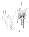
- FIG. 1 shows a cross-sectional view of a non-aqueous electrolyte secondary battery manufactured by the secondary battery manufacturing method of the first embodiment.
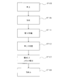
- FIG. 2 is a process procedure diagram for explaining the method for manufacturing the secondary battery according to the first embodiment.
- FIG. 1A shows a perspective view of a nonaqueous electrolyte secondary battery
- FIG. 1B shows a cross-sectional view taken along line AA in FIG.
- a non-aqueous electrolyte secondary battery 1 manufactured by the manufacturing method of the present embodiment is a large-capacity lithium suitable for driving a vehicle on which a non-aqueous electrolyte secondary battery is mounted, for example.
- An ion secondary battery having an electrode size of, for example, 210 mm ⁇ 297 mm or 148 mm ⁇ 210 mm, and a capacity of 4 Ah or more.
- the nonaqueous electrolyte secondary battery 1 manufactured in the present embodiment includes an electrode laminate 5 in which a separator 4 is disposed between a positive electrode 3a and a negative electrode 3b, an electrolytic solution, And an exterior body 6 made of a laminate film 6a for sealing them.
- the outer package 6 may be formed by bending one laminated film 6a and heat-sealing the three surrounding sides, or by overlapping two sheets and heat-sealing the four surrounding sides.
- the thickness of the laminate film 6a is preferably about 100 ⁇ m to 200 ⁇ m, and is a flexible film.
- the negative electrode 3 b, the positive electrode 3 a, and the separator 4 that are the electrodes 3 are formed in a rectangular shape, and the negative electrodes 3 b and the positive electrodes 3 a are alternately stacked via the separator 4. Negative electrodes 3b are respectively disposed at both ends of the electrode stack 5 in the stacking direction.
- the positive electrode 3a is formed by applying a positive electrode active material 10a to a current collecting aluminum foil 9a, and a composite oxide such as LiCoO 2 or LiMnO 2 is used as the positive electrode active material 10a.
- a negative electrode active material 10b is applied to a current collector copper foil 9b, and graphite, amorphous carbon, or the like is used as the negative electrode active material 9b.
- An insulating tape 11 for preventing a short circuit between the negative electrode 3b and the positive electrode 3a is attached to the boundary between the positive electrode active material 10a and the current collector aluminum foil 9a.
- the negative electrode terminal 7b is connected to the tip of the portion of the electrode laminate 5 that extends from the current collector copper foil 9b of the negative electrode 3b, and one end of the negative electrode terminal 7b is connected to the portion that extends from the current collector copper foil 9b. The other end on the opposite side is connected and protrudes outside the exterior body 6.
- the positive terminal 7a is similarly configured. Both the negative electrode terminal 7 b and the positive electrode terminal 7 a may protrude from one side of the rectangular outer package 6, or may protrude from both sides of the rectangular outer package 6 facing each other.
- the laminate film forming the outer package 6 is formed by laminating a heat sealing layer (inner layer), a metal layer, and a protective layer (outer layer) in this order.
- the inner layer is formed of a polyolefin resin.
- the metal layer is formed of aluminum foil.
- the outer layer is made of PET (polyethylene terephthalate).
- a rectangular frame-shaped space is formed in the exterior body 6 over the outer peripheral edge of the electrode laminate 5, and gas generated when the secondary battery is used. It functions as a gas reservoir 8 for accumulating gas.
- the gas reservoir 8 is also used as a space for storing the gas pushed out between the electrodes 3 of the electrode stack 5 in the pressurizing process described later.
- the manufacturing method of the secondary battery according to the first embodiment includes an electrode laminate 5 in which a separator 4 is arranged between a positive electrode 3a and a negative electrode 3b, and an electrolyte solution from a laminate film.
- the gas removal process which opens and removes under pressure reduction, and the re-sealing process which seals the exterior body 6 under pressure reduction after a gas removal process.
- the electrode laminate 5 is housed in the exterior body 6, an electrolyte is injected, and the opening of the exterior body 6 is sealed under reduced pressure.
- the electrolyte LiPF 6 (lithium hexafluorophosphate), LiBF 4 (lithium tetrafluoroborate), LiClO 4 (lithium perchlorate) or the like can be used, and as the solvent, PC (propylene carbonate). ), EC (ethylene carbonate), DEC (diethyl carbonate), or the like.
- the degree of reduced pressure (degree of vacuum) in the sealing step is preferably about 1 hPa to 100 hPa.
- step ST102 charging is performed up to 100% of the capacity (full charge).
- step ST103 a part of the outer package 6 is opened, and the gas generated in the outer package 6 is discharged outside under reduced pressure.
- the exterior body 6 may be opened after being opened, or the exterior body 6 may be opened under reduced pressure.
- step ST104 the outer package 6 opened in the gas removal process is sealed under reduced pressure.
- the degree of reduced pressure in the gas removal step and the reseal step is preferably about 1 hPa to 100 hPa.
- the outer body 6 is again deflated by reducing the pressure, so that the gas reservoir 8 can be used as a space for storing gas generated when the secondary battery is used.
- the gas reservoir portion 8 functions as a space for storing gas both when the secondary battery is manufactured and when the secondary battery is used.
- the exterior body has a rigid structure like a hard case, when the exterior body is deformed by the gas accumulated during the manufacture of the secondary battery, a plurality of cells must be stored in the module. Therefore, an exterior body formed of a flexible laminate film is preferable.
- the electrode stack 5 and the electrolytic solution are placed in the exterior body 6 in the sealing step by performing the sealing step under reduced pressure.
- Gas generated when stored can be removed smoothly.
- the influence of the gas in a charge process can be reduced, without opening the exterior body 6 and performing a gas removal process before a charge process.
- the gas produced in the exterior body 6 at the charging process can be smoothly removed outside the exterior body 6 by removing the gas under reduced pressure after the charging process. As a result, the number of gas removal steps can be reduced and the influence of the gas on the battery characteristics can be suppressed.
- FIG. 3 is a process flowchart for explaining the method for manufacturing the secondary battery according to the second embodiment.
- 2nd Embodiment it has a pressurization process which pressurizes the exterior body 6 sealed by the sealing process between a sealing process and a charge process.
- the same steps as those of the manufacturing method of the first embodiment are denoted by the same reference numerals as those of the first embodiment, and description thereof is omitted.
- the same components as those of the nonaqueous electrolyte secondary battery in the first embodiment are denoted by the same reference numerals as those in the first embodiment.
- the manufacturing method of the secondary battery according to the second embodiment includes an electrode laminate 5 in which a separator 4 is disposed between a positive electrode 3a and a negative electrode 3b, and an electrolyte solution from a laminate film.
- the electrode laminate 5 is housed in the exterior body 6, an electrolyte is injected, and the opening of the exterior body 6 is sealed.
- the electrolyte and the solvent used in the first embodiment can be used.
- step ST106 in FIG. 3 flat plate press processing using a flat plate is performed while the exterior body 6 is still sealed.
- the gas in the electrode stack 5 is moved to the outside of the electrode stack 5 in the outer package 6.
- the surface of the flat plate press is made of an insulating material, and is preferably made of a resin material.
- the gas reservoir 8 of the outer package 6 is squeezed, but by moving the gas, the flexible laminate film swells and the gas can be stored in the gas reservoir 8.
- Flat plate pressing is preferably performed at a pressure of about 1 kgf / cm 2 to 100 kgf / cm 2 .
- step ST102 charging is performed up to 100% of the capacity (full charge).
- step ST107 a part of the outer package 6 is opened, a nozzle is inserted into the opening, and the gas inside the outer package 6 is sucked and removed through the nozzle.
- step ST108 the opened exterior body 6 is sealed.
- sealing step (step ST105), the gas removing step (step 107), and the resealing step (step 108) in the second embodiment may be performed under reduced pressure as in Modification 2B described later. .
- the gas generated in the exterior body 6 after the sealing step is transferred from the electrode laminate 5 to the gas reservoir 8. Therefore, the influence of the gas in the charging process can be reduced without opening the outer package 6 and performing the gas removing process before the charging process. Moreover, this embodiment can suppress that a battery characteristic falls by the gas produced in the exterior body 6 at the charge process by performing a gas removal process after a charge process. As a result, the number of gas removal steps can be reduced and the influence of the gas on the battery characteristics can be suppressed.
- the surface of the roll press is made of an insulating material and is preferably made of a resin material.
- both the negative electrode terminal 7b and the positive electrode terminal 7a protrude from one side of the outer package 6 or the type in which the negative electrode terminal 7b and the positive electrode terminal 7a protrude from both opposite sides of the outer package 6, respectively.
- the insulating tape 11 may be attached to the negative electrode 3b side.
- the roller may be rolled and moved toward the other end opposite to the one end. Thereby, the gas collected in the vicinity of the insulating tape 11 can be moved efficiently.
- the gas generated in the outer package 6 after the sealing step can be smoothly moved from the electrode laminate 5 into the gas reservoir 8.
- the influence of the gas in the charging process can be reduced without opening the outer package 6 and performing the gas removing process before the process.
- this embodiment can suppress that a battery characteristic falls by the gas produced in the exterior body 6 at the charge process by performing a gas removal process after a charge process. As a result, the number of gas removal steps can be reduced and the influence of the gas on the battery characteristics can be suppressed.
- Modification 2B of the second embodiment The gas removal process in the second embodiment is performed under reduced pressure instead of the suction method using a nozzle, or the re-sealing process is performed under reduced pressure.
- the accumulated gas can be smoothly removed outside the exterior body 6.
- the sealing step in the second embodiment under reduced pressure the gas generated when the electrode stack 5 and the electrolytic solution are stored in the exterior body 6 can be smoothly removed to the outside of the exterior body 6. Can do.
- Modification 2A and Modification 2B may be applied in combination.
- FIG. 4 the process sequence diagram for demonstrating the manufacturing method of the secondary battery of 3rd Embodiment is shown. Also in the third embodiment, the same steps as those of the manufacturing method of the first embodiment are denoted by the same reference numerals as those of the first embodiment, and description thereof is omitted. Also in the third embodiment, the same components as those of the nonaqueous electrolyte secondary battery in the first embodiment are denoted by the same reference numerals as those in the first embodiment.
- the manufacturing method of the secondary battery according to the third embodiment includes an electrode laminate 5 in which a separator 4 is disposed between a positive electrode 3a and a negative electrode 3b, and an electrolyte solution from a laminate film.
- a second charging step for charging to full charge without opening the exterior body 6 after the first charging step, and opening the exterior body 6 for the gas generated in the exterior body 6 in the second charging step.
- a gas removal step of sucking and removing the gas by inserting a nozzle into the opening and a re-sealing step of sealing the outer package 6 after the gas removal step.
- the electrode laminate 5 is housed in the exterior body 6, an electrolyte is injected, and the opening of the exterior body 6 is sealed.
- the electrolyte and the solvent used in the first embodiment can be used.
- step ST106 in FIG. 4 flat plate pressing using a flat plate is performed while the exterior body 6 is sealed as in the second embodiment described above. As a result, the gas generated in the outer package 6 is moved from the electrode stack 5 into the gas reservoir 8.
- the battery is charged to a voltage less than the full charge voltage, for example, about 5% to 50% of the capacity.
- charging is performed up to 100% (full charge) of the capacity.
- step ST107 a part of the outer package 6 is opened, a nozzle is inserted into the opening, and the gas inside the outer package 6 is sucked and removed through the nozzle.
- step ST108 the opened exterior body 6 is sealed.
- the gas generated in the exterior body 6 in the charging step causes deterioration of the battery characteristics. Can be suppressed. As a result, the number of gas removal steps can be reduced and the influence of the gas on the battery characteristics can be suppressed.
- Modification 3B of the third embodiment Similarly to the above-described modification 2B of the second embodiment, the gas removal process in the third embodiment is performed under reduced pressure, thereby smoothly removing the gas generated in the charging process to the outside of the exterior body 6. Can do. In addition, by performing the sealing step in the third embodiment under reduced pressure, the gas generated when the electrode laminate 5 and the electrolytic solution are stored in the exterior body 6 can be smoothly removed to the outside of the exterior body 6. Can do.
- FIG. 5 the process sequence diagram for demonstrating the manufacturing method of the secondary battery of 4th Embodiment is shown.
- the fourth embodiment is different from the third embodiment in that a pressurizing step is performed between the first charging step and the second charging step in the third embodiment.
- the same steps as those of the manufacturing method of the first embodiment are denoted by the same reference numerals as those of the first embodiment, and the description thereof is omitted.
- the same components as those of the nonaqueous electrolyte secondary battery in the first embodiment are denoted by the same reference numerals as those in the first embodiment.
- the manufacturing method of the secondary battery according to the fourth embodiment includes an electrode laminate 5 in which a separator 4 is disposed between a positive electrode 3a and a negative electrode 3b, and an electrolytic solution from a laminate film.
- the electrode stack 5 was stored after the first charging step after the first charging step and the sealing step for storing and sealing in the outer package 6 to be formed, the first charging step for charging to less than the fully charged voltage after the sealing step
- the electrode laminate 5 is stored in the exterior body 6, an electrolyte is injected, and the opening of the exterior body 6 is sealed.
- the electrolyte and the solvent used in the first embodiment can be used.
- the battery is charged to a voltage less than the full charge voltage, for example, about 5% to 50% of the capacity.
- step ST106 in FIG. 5 As in the second embodiment described above, flat plate pressing using a flat plate is performed while the exterior body 6 remains sealed. As a result, a large amount of gas generated in the exterior body 6 in the first charging step can be moved from the electrode laminate 5 into the gas reservoir 8.
- step ST112 charging is performed up to 100% (full charge) of the capacity.
- step ST107 a part of the outer package 6 is opened, a nozzle is inserted into the opening, and the gas inside the outer package 6 is sucked and removed through the nozzle.
- step ST108 the opened exterior body 6 is sealed.
- an exterior is formed in the sealing step and the first charging step by performing a pressurizing step between the first charging step and the second charging step. Since a large amount of gas generated in the body 6 can be moved from the electrode laminate 5 into the gas reservoir 8, the outer body 6 is opened before the second charging step and the gas removal step is performed. In addition, the influence of gas in the second charging step can be reduced.
- the gas removal step is performed after the second charging step, thereby suppressing the deterioration of the battery characteristics due to the gas generated in the exterior body 6 in the second charging step. it can. As a result, the number of gas removal steps can be reduced and the influence of the gas on the battery characteristics can be suppressed.
- the gas that has moved the gas reservoir 8 for containing the gas generated when the secondary battery 1 is used from the electrode stack 5 during manufacture is used.
- the secondary battery 1 can be manufactured without requiring an additional step of cutting the gas reservoir 8 used at the time of manufacture from the secondary battery 1.
- the pressurizing step when pressing using a roll, from one end of the insulating tape 11 affixed to the boundary portion between the active material layer constituting the positive electrode or the negative electrode and the current collector copper foil, The roller is moved in the direction of the other end on the opposite side. Thereby, the gas collected in the vicinity of the insulating tape 11 can be moved efficiently.
- Modification 4B of the fourth embodiment Similar to the modified example 2B of the second embodiment described above, in the fourth embodiment, the pressure is reduced after the exterior body 6 is opened to remove the gas. Thus, the gas generated in the second charging step can be smoothly removed outside the exterior body 6. Further, by performing the resealing step under reduced pressure, the gas reservoir 8 can be squeezed and used as a gas reservoir for storing gas generated when the secondary battery is used. In addition, by performing the sealing step in the fourth embodiment under reduced pressure, the gas generated when the electrode laminate 5 and the electrolytic solution are stored in the exterior body 6 is smoothly removed to the outside of the exterior body 6. Can do.
- the exterior body 6 may be decompressed after being opened, or may be opened after being decompressed.
- the manufacturing method of the secondary battery of each embodiment mentioned above is another pressurization which pressurizes in the lamination direction in the state comprised as a module, when a secondary battery (cell) is laminated
- the method for manufacturing a secondary battery according to the present invention is applied to a secondary battery in which an electrode laminate in which a separator is disposed between a positive electrode and a negative electrode and wound in a spiral shape.
- an electrode laminate in which a separator is disposed between a positive electrode and a negative electrode and wound in a spiral shape may be.
Landscapes
- Chemical & Material Sciences (AREA)
- Chemical Kinetics & Catalysis (AREA)
- Electrochemistry (AREA)
- General Chemical & Material Sciences (AREA)
- Engineering & Computer Science (AREA)
- Manufacturing & Machinery (AREA)
- Inorganic Chemistry (AREA)
- Secondary Cells (AREA)
- Connection Of Batteries Or Terminals (AREA)
- Battery Electrode And Active Subsutance (AREA)
- Sealing Battery Cases Or Jackets (AREA)
Abstract
La présente invention comprend : une étape de scellage (ST105) dans laquelle une solution d'électrolyte et un empilement d'électrode, dans lequel un séparateur est disposé entre une électrode positive et une électrode négative, sont logés et scellés dans un couvercle extérieur comprenant un film stratifié ; une étape de pressurisation (ST106) dans laquelle une presse à plaque plate ou analogue est utilisée pour appliquer une pression sur le couvercle extérieur dans lequel l'empilement d'électrode est logé ; une étape de chargement (ST102) dans laquelle la batterie est chargée jusqu'à sa totalité ; une étape de retrait de gaz (ST107) dans laquelle le couvercle extérieur est ouvert et le gaz généré à l'intérieur du couvercle extérieur dans l'étape de chargement est retiré ; et une étape de rescellage (ST108) pour le scellage du couvercle extérieur après l'étape de retrait de gaz. En résultat, l'étape de retrait de gaz n'a besoin d'être effectuée que quelques fois, et l'effet du gaz sur les caractéristiques de batterie est inhibé.
Priority Applications (3)
| Application Number | Priority Date | Filing Date | Title |
|---|---|---|---|
| EP13738170.3A EP2806492B1 (fr) | 2012-01-20 | 2013-01-10 | Procédé de fabrication pour batterie secondaire à électrolyte non aqueux |
| CN201380005870.1A CN104054208B (zh) | 2012-01-20 | 2013-01-10 | 非水电解质二次电池的制造方法 |
| US14/372,892 US9647297B2 (en) | 2012-01-20 | 2013-01-10 | Production method for non-aqueous electrolyte secondary battery |
Applications Claiming Priority (2)
| Application Number | Priority Date | Filing Date | Title |
|---|---|---|---|
| JP2012-009911 | 2012-01-20 | ||
| JP2012009911A JP6010302B2 (ja) | 2012-01-20 | 2012-01-20 | 非水電解質二次電池の製造方法 |
Publications (1)
| Publication Number | Publication Date |
|---|---|
| WO2013108708A1 true WO2013108708A1 (fr) | 2013-07-25 |
Family
ID=48799134
Family Applications (1)
| Application Number | Title | Priority Date | Filing Date |
|---|---|---|---|
| PCT/JP2013/050315 Ceased WO2013108708A1 (fr) | 2012-01-20 | 2013-01-10 | Procédé de fabrication pour batterie secondaire à électrolyte non aqueux |
Country Status (5)
| Country | Link |
|---|---|
| US (1) | US9647297B2 (fr) |
| EP (1) | EP2806492B1 (fr) |
| JP (1) | JP6010302B2 (fr) |
| CN (1) | CN104054208B (fr) |
| WO (1) | WO2013108708A1 (fr) |
Cited By (6)
| Publication number | Priority date | Publication date | Assignee | Title |
|---|---|---|---|---|
| WO2015145852A1 (fr) * | 2014-03-25 | 2015-10-01 | Necエナジーデバイス株式会社 | Procédé de production de batterie secondaire |
| WO2015173686A1 (fr) * | 2014-05-16 | 2015-11-19 | Semiconductor Energy Laboratory Co., Ltd. | Dispositif électronique avec batterie secondaire |
| JP2017004885A (ja) * | 2015-06-15 | 2017-01-05 | オートモーティブエナジーサプライ株式会社 | 二次電池の製造方法および製造装置 |
| CN109755652A (zh) * | 2017-11-06 | 2019-05-14 | 汽车能源供应公司 | 薄膜外装电池的加压方法和制造方法 |
| JPWO2023119401A1 (fr) * | 2021-12-21 | 2023-06-29 | ||
| WO2023119402A1 (fr) * | 2021-12-21 | 2023-06-29 | 京セラ株式会社 | Procédé de fabrication de batterie auxiliaire |
Families Citing this family (12)
| Publication number | Priority date | Publication date | Assignee | Title |
|---|---|---|---|---|
| WO2015019514A1 (fr) * | 2013-08-09 | 2015-02-12 | Necエナジーデバイス株式会社 | Batterie secondaire et son procédé de fabrication |
| JP6260266B2 (ja) * | 2013-12-26 | 2018-01-17 | 三菱自動車工業株式会社 | 二次電池 |
| KR101704760B1 (ko) * | 2014-01-08 | 2017-02-08 | 주식회사 엘지화학 | 가압 트레이 |
| KR101889675B1 (ko) | 2015-02-16 | 2018-08-17 | 닛산 지도우샤 가부시키가이샤 | 리튬 이온 이차 전지의 제조 방법 |
| JP6606341B2 (ja) * | 2015-04-15 | 2019-11-13 | 株式会社エンビジョンAescジャパン | 電極および電池 |
| JP6551220B2 (ja) * | 2015-12-25 | 2019-07-31 | トヨタ自動車株式会社 | 全固体電池の製造方法 |
| KR102465163B1 (ko) | 2016-06-22 | 2022-11-08 | 가부시키가이샤 한도오따이 에네루기 켄큐쇼 | 전지, 및 전지의 제작 방법 |
| CN107579282B (zh) * | 2017-09-14 | 2020-04-14 | 合肥国轩高科动力能源有限公司 | 一种软包制硅碳负极锂电池化成工艺 |
| KR102265741B1 (ko) | 2018-03-21 | 2021-06-16 | (주)엘지에너지솔루션 | 리튬 이차 전지의 제조방법 및 이에 의해 제조된 리튬 이차 전지 |
| KR102847783B1 (ko) | 2020-05-07 | 2025-08-19 | 주식회사 엘지에너지솔루션 | 디개싱장치 및 디개싱방법 |
| KR102931772B1 (ko) * | 2020-07-06 | 2026-02-26 | 주식회사 엘지에너지솔루션 | 이차전지 제조방법 및 이차전지 제조장치 |
| KR102798474B1 (ko) | 2020-12-01 | 2025-04-22 | 주식회사 엘지에너지솔루션 | 전지 셀의 충방전 장치 및 이를 이용한 전지 셀의 충방전 방법 |
Citations (5)
| Publication number | Priority date | Publication date | Assignee | Title |
|---|---|---|---|---|
| JPH10308240A (ja) * | 1997-05-09 | 1998-11-17 | Sanyo Electric Co Ltd | 電池の製造方法 |
| JP2001093580A (ja) * | 1999-09-21 | 2001-04-06 | Tdk Corp | シート型電池の製造方法 |
| JP2008262895A (ja) | 2007-03-16 | 2008-10-30 | Nec Tokin Corp | リチウムポリマー電池の製造方法 |
| JP2009187711A (ja) * | 2008-02-04 | 2009-08-20 | Fdk Corp | 電気化学的デバイスの製造方法、および電気化学的デバイス |
| JP2010009983A (ja) * | 2008-06-27 | 2010-01-14 | Toyota Motor Corp | 充電ムラ低減方法、及び、二次電池の製造方法 |
Family Cites Families (10)
| Publication number | Priority date | Publication date | Assignee | Title |
|---|---|---|---|---|
| US5871865A (en) * | 1997-05-15 | 1999-02-16 | Valence Technology, Inc. | Methods of fabricating electrochemical cells |
| CN1197190C (zh) * | 2000-01-27 | 2005-04-13 | 索尼株式会社 | 凝胶电解液电池的制造方法 |
| US6835214B2 (en) * | 2001-06-18 | 2004-12-28 | Japan Storage Battery Co., Ltd. | Process for the production of non-aqueous electrolyte battery |
| KR100804522B1 (ko) | 2001-11-29 | 2008-02-20 | 삼성에스디아이 주식회사 | 이차전지의 제조방법 |
| JP2003331916A (ja) | 2002-05-08 | 2003-11-21 | Tdk Corp | 二次電池および二次電池の製造方法 |
| JP5119652B2 (ja) | 2006-11-22 | 2013-01-16 | 日産自動車株式会社 | 双極型電池の製造方法 |
| JP5315653B2 (ja) * | 2006-12-08 | 2013-10-16 | 日産自動車株式会社 | バイポーラ電池の製造方法 |
| EP1930977B1 (fr) * | 2006-12-08 | 2012-05-30 | Nissan Motor Co., Ltd. | Batterie bipolaire et procédé de sa fabrication |
| CN101340009A (zh) * | 2007-07-05 | 2009-01-07 | 黄穗阳 | 聚合物电解质硬包装锂离子电池 |
| US8652668B2 (en) * | 2010-02-15 | 2014-02-18 | Sharp Kabushiki Kaisha | Secondary battery; solar power generation system, wind power generation system, and vehicle provided therewith; and method for fabrication of a secondary battery |
-
2012
- 2012-01-20 JP JP2012009911A patent/JP6010302B2/ja active Active
-
2013
- 2013-01-10 US US14/372,892 patent/US9647297B2/en active Active
- 2013-01-10 EP EP13738170.3A patent/EP2806492B1/fr active Active
- 2013-01-10 WO PCT/JP2013/050315 patent/WO2013108708A1/fr not_active Ceased
- 2013-01-10 CN CN201380005870.1A patent/CN104054208B/zh active Active
Patent Citations (5)
| Publication number | Priority date | Publication date | Assignee | Title |
|---|---|---|---|---|
| JPH10308240A (ja) * | 1997-05-09 | 1998-11-17 | Sanyo Electric Co Ltd | 電池の製造方法 |
| JP2001093580A (ja) * | 1999-09-21 | 2001-04-06 | Tdk Corp | シート型電池の製造方法 |
| JP2008262895A (ja) | 2007-03-16 | 2008-10-30 | Nec Tokin Corp | リチウムポリマー電池の製造方法 |
| JP2009187711A (ja) * | 2008-02-04 | 2009-08-20 | Fdk Corp | 電気化学的デバイスの製造方法、および電気化学的デバイス |
| JP2010009983A (ja) * | 2008-06-27 | 2010-01-14 | Toyota Motor Corp | 充電ムラ低減方法、及び、二次電池の製造方法 |
Non-Patent Citations (1)
| Title |
|---|
| See also references of EP2806492A4 |
Cited By (16)
| Publication number | Priority date | Publication date | Assignee | Title |
|---|---|---|---|---|
| JPWO2015145852A1 (ja) * | 2014-03-25 | 2017-04-13 | Necエナジーデバイス株式会社 | 二次電池の製造方法 |
| WO2015145852A1 (fr) * | 2014-03-25 | 2015-10-01 | Necエナジーデバイス株式会社 | Procédé de production de batterie secondaire |
| TWI683468B (zh) * | 2014-05-16 | 2020-01-21 | 日商半導體能源研究所股份有限公司 | 具備二次電池的電子裝置 |
| WO2015173686A1 (fr) * | 2014-05-16 | 2015-11-19 | Semiconductor Energy Laboratory Co., Ltd. | Dispositif électronique avec batterie secondaire |
| US9640831B2 (en) | 2014-05-16 | 2017-05-02 | Semiconductor Energy Laboratory Co., Ltd. | Electronic device with secondary battery |
| US10056578B2 (en) | 2014-05-16 | 2018-08-21 | Semiconductor Energy Laboratory Co., Ltd. | Electronic device with secondary battery |
| TWI673904B (zh) * | 2014-05-16 | 2019-10-01 | 日商半導體能源研究所股份有限公司 | 具備二次電池的電子裝置 |
| JP2017004885A (ja) * | 2015-06-15 | 2017-01-05 | オートモーティブエナジーサプライ株式会社 | 二次電池の製造方法および製造装置 |
| CN109755652B (zh) * | 2017-11-06 | 2022-03-25 | 远景Aesc日本有限公司 | 薄膜外装电池的加压方法和制造方法 |
| CN109755652A (zh) * | 2017-11-06 | 2019-05-14 | 汽车能源供应公司 | 薄膜外装电池的加压方法和制造方法 |
| JPWO2023119401A1 (fr) * | 2021-12-21 | 2023-06-29 | ||
| WO2023119402A1 (fr) * | 2021-12-21 | 2023-06-29 | 京セラ株式会社 | Procédé de fabrication de batterie auxiliaire |
| WO2023119401A1 (fr) * | 2021-12-21 | 2023-06-29 | 京セラ株式会社 | Procédé de fabrication de batterie secondaire |
| JPWO2023119402A1 (fr) * | 2021-12-21 | 2023-06-29 | ||
| JP7692499B2 (ja) | 2021-12-21 | 2025-06-13 | 京セラ株式会社 | 二次電池の製造方法 |
| JP7753390B2 (ja) | 2021-12-21 | 2025-10-14 | 京セラ株式会社 | 二次電池の製造方法 |
Also Published As
| Publication number | Publication date |
|---|---|
| CN104054208A (zh) | 2014-09-17 |
| EP2806492B1 (fr) | 2019-04-10 |
| JP2013149521A (ja) | 2013-08-01 |
| EP2806492A4 (fr) | 2015-10-07 |
| US9647297B2 (en) | 2017-05-09 |
| US20140352140A1 (en) | 2014-12-04 |
| JP6010302B2 (ja) | 2016-10-19 |
| EP2806492A1 (fr) | 2014-11-26 |
| CN104054208B (zh) | 2016-12-28 |
Similar Documents
| Publication | Publication Date | Title |
|---|---|---|
| JP6010302B2 (ja) | 非水電解質二次電池の製造方法 | |
| KR102256599B1 (ko) | 가압 지그 및 이를 이용한 이차전지 제조 방법 | |
| US8277970B2 (en) | Pouch-type secondary battery having an non-sealing residue portion | |
| EP2802025B1 (fr) | Cellule de batterie à structure en escalier | |
| JP6572204B2 (ja) | 二次電池とその製造方法 | |
| US9472796B2 (en) | Stacked secondary battery with separator between electrodes | |
| KR20130133639A (ko) | 전극 조립체, 전지셀, 전극 조립체의 제조방법 및 전지셀의 제조 방법 | |
| CN103682232A (zh) | 电池 | |
| JP2010097891A (ja) | 積層型リチウムイオン二次電池 | |
| JP2010198988A (ja) | フィルムケース型蓄電デバイス | |
| JP6113972B2 (ja) | 二次電池 | |
| CN114824336A (zh) | 固态电池和固态电池单元 | |
| JP5623073B2 (ja) | 二次電池 | |
| KR101420060B1 (ko) | 파우치 외장재 실링용 실링툴 및 파우치형 이차전지의 제조방법 | |
| KR101825007B1 (ko) | 파우치형 이차전지 및 그 제조방법 | |
| KR101243560B1 (ko) | 파우치형 리튬 이차 전지 | |
| JP6682203B2 (ja) | 二次電池の製造方法 | |
| CN110495045B (zh) | 二次电池及其制造方法 | |
| CN221262464U (zh) | 电池单体、电池和用电设备 | |
| CN119627033A (zh) | 电池单体及其生产设备和方法、电池装置、用电装置 | |
| JP6721059B2 (ja) | 二次電池 | |
| KR20240027551A (ko) | 리튬 이차전지의 활성화 방법 | |
| JP2003303577A (ja) | 密閉型電池 | |
| CN223638486U (zh) | 一种电池装置、用电设备和储能装置 | |
| CN223713025U (zh) | 电池单体、电池装置及用电装置 |
Legal Events
| Date | Code | Title | Description |
|---|---|---|---|
| 121 | Ep: the epo has been informed by wipo that ep was designated in this application |
Ref document number: 13738170 Country of ref document: EP Kind code of ref document: A1 |
|
| WWE | Wipo information: entry into national phase |
Ref document number: 14372892 Country of ref document: US |
|
| NENP | Non-entry into the national phase |
Ref country code: DE |
|
| WWE | Wipo information: entry into national phase |
Ref document number: 2013738170 Country of ref document: EP |