WO2013108866A1 - Joint d'embout et compresseur à carter spirale correspondant - Google Patents
Joint d'embout et compresseur à carter spirale correspondant Download PDFInfo
- Publication number
- WO2013108866A1 WO2013108866A1 PCT/JP2013/050895 JP2013050895W WO2013108866A1 WO 2013108866 A1 WO2013108866 A1 WO 2013108866A1 JP 2013050895 W JP2013050895 W JP 2013050895W WO 2013108866 A1 WO2013108866 A1 WO 2013108866A1
- Authority
- WO
- WIPO (PCT)
- Prior art keywords
- seal
- tip
- scroll
- scroll compressor
- spiral
- Prior art date
- Legal status (The legal status is an assumption and is not a legal conclusion. Google has not performed a legal analysis and makes no representation as to the accuracy of the status listed.)
- Ceased
Links
Images


Classifications
-
- F—MECHANICAL ENGINEERING; LIGHTING; HEATING; WEAPONS; BLASTING
- F04—POSITIVE - DISPLACEMENT MACHINES FOR LIQUIDS; PUMPS FOR LIQUIDS OR ELASTIC FLUIDS
- F04C—ROTARY-PISTON, OR OSCILLATING-PISTON, POSITIVE-DISPLACEMENT MACHINES FOR LIQUIDS; ROTARY-PISTON, OR OSCILLATING-PISTON, POSITIVE-DISPLACEMENT PUMPS
- F04C18/00—Rotary-piston pumps specially adapted for elastic fluids
- F04C18/02—Rotary-piston pumps specially adapted for elastic fluids of arcuate-engagement type, i.e. with circular translatory movement of co-operating members, each member having the same number of teeth or tooth-equivalents
- F04C18/0207—Rotary-piston pumps specially adapted for elastic fluids of arcuate-engagement type, i.e. with circular translatory movement of co-operating members, each member having the same number of teeth or tooth-equivalents both members having co-operating elements in spiral form
- F04C18/0215—Rotary-piston pumps specially adapted for elastic fluids of arcuate-engagement type, i.e. with circular translatory movement of co-operating members, each member having the same number of teeth or tooth-equivalents both members having co-operating elements in spiral form where only one member is moving
-
- F—MECHANICAL ENGINEERING; LIGHTING; HEATING; WEAPONS; BLASTING
- F04—POSITIVE - DISPLACEMENT MACHINES FOR LIQUIDS; PUMPS FOR LIQUIDS OR ELASTIC FLUIDS
- F04C—ROTARY-PISTON, OR OSCILLATING-PISTON, POSITIVE-DISPLACEMENT MACHINES FOR LIQUIDS; ROTARY-PISTON, OR OSCILLATING-PISTON, POSITIVE-DISPLACEMENT PUMPS
- F04C18/00—Rotary-piston pumps specially adapted for elastic fluids
- F04C18/02—Rotary-piston pumps specially adapted for elastic fluids of arcuate-engagement type, i.e. with circular translatory movement of co-operating members, each member having the same number of teeth or tooth-equivalents
- F04C18/0207—Rotary-piston pumps specially adapted for elastic fluids of arcuate-engagement type, i.e. with circular translatory movement of co-operating members, each member having the same number of teeth or tooth-equivalents both members having co-operating elements in spiral form
- F04C18/0246—Details concerning the involute wraps or their base, e.g. geometry
- F04C18/0269—Details concerning the involute wraps
- F04C18/0276—Different wall heights
-
- F—MECHANICAL ENGINEERING; LIGHTING; HEATING; WEAPONS; BLASTING
- F04—POSITIVE - DISPLACEMENT MACHINES FOR LIQUIDS; PUMPS FOR LIQUIDS OR ELASTIC FLUIDS
- F04C—ROTARY-PISTON, OR OSCILLATING-PISTON, POSITIVE-DISPLACEMENT MACHINES FOR LIQUIDS; ROTARY-PISTON, OR OSCILLATING-PISTON, POSITIVE-DISPLACEMENT PUMPS
- F04C18/00—Rotary-piston pumps specially adapted for elastic fluids
- F04C18/02—Rotary-piston pumps specially adapted for elastic fluids of arcuate-engagement type, i.e. with circular translatory movement of co-operating members, each member having the same number of teeth or tooth-equivalents
- F04C18/0207—Rotary-piston pumps specially adapted for elastic fluids of arcuate-engagement type, i.e. with circular translatory movement of co-operating members, each member having the same number of teeth or tooth-equivalents both members having co-operating elements in spiral form
- F04C18/0246—Details concerning the involute wraps or their base, e.g. geometry
- F04C18/0269—Details concerning the involute wraps
- F04C18/0284—Details of the wrap tips
-
- F—MECHANICAL ENGINEERING; LIGHTING; HEATING; WEAPONS; BLASTING
- F04—POSITIVE - DISPLACEMENT MACHINES FOR LIQUIDS; PUMPS FOR LIQUIDS OR ELASTIC FLUIDS
- F04C—ROTARY-PISTON, OR OSCILLATING-PISTON, POSITIVE-DISPLACEMENT MACHINES FOR LIQUIDS; ROTARY-PISTON, OR OSCILLATING-PISTON, POSITIVE-DISPLACEMENT PUMPS
- F04C27/00—Sealing arrangements in rotary-piston pumps specially adapted for elastic fluids
- F04C27/005—Axial sealings for working fluid
Definitions
- the present invention relates to a tip seal suitable for application to a scroll compressor and a scroll compressor using the same.
- a tip seal is provided on the tooth tip surface of the spiral wrap. This tip seal is fitted and installed in a groove provided on the tooth tip surface of the spiral wrap, and the surface thereof is slid in contact with the tooth bottom surface of the counterpart scroll, so that the tooth tip surface and the tooth bottom surface are in contact with each other. The gap between them is sealed.
- the tip seal is usually fitted in a groove provided on the tip of the spiral wrap of the fixed scroll and the orbiting scroll so that a gas pressure is applied to the back side, and the surface of the tip seal is generated by the gas pressure. Is pressed against the tooth bottom surface of the other party's scroll to ensure sealing performance (see, for example, Patent Document 1).
- the tip seal is a stepped scroll compressor in which stepped portions are provided at arbitrary positions along the spiral direction of the tooth tip surface and the tooth bottom surface of the spiral wrap of the fixed scroll and the orbiting scroll. It is usual to install on the inner peripheral side and the outer peripheral side of the tooth tip surface with the part as a boundary (see, for example, Patent Document 2).
- chip seals are made of, for example, a rubber material such as polyphenylene sulfide (PPS), polyether ether ketone (PEEK), polytetrafluoroethylene (PTFE), fluoro rubber, or a composite material thereof, and has an elongated rectangular cross section. It is a spiral seal material.
- a chip seal having a two-layer structure by applying a hard coating on the surface side is disclosed in Patent Document 1.
- the chip seal needs to ensure sufficient wear resistance and slidability, and the resin material as described above is generally used. However, since the cross-sectional area is very small and thin, sufficient flexibility is ensured. It is difficult to ensure strength. On the other hand, it is conceivable to use a harder material in order to reduce the deflection, but there is a possibility of causing problems such as wear of the other party scroll. Therefore, in use, the tip seal is installed so as not to be cantilevered, and the risk of breakage due to bending of the end portion is avoided.
- the tooth tip surface may cross the discharge port at the inner peripheral end or outer peripheral end of the spiral wrap, or may turn away from the end plate of the other scroll.
- the tip seal is not provided in these portions.
- the end portion of the tip seal is placed away from the end portion of the tooth tip surface or the step portion of the tooth tip surface.
- the present invention has been made in view of such circumstances, and by ensuring the strength against bending of the chip seal, the chip seal that can expand its use range or installation range and improve the sealing function.
- Another object of the present invention is to provide a scroll compressor using the same.
- the chip seal of the present invention and the scroll compressor using the same employ the following means. That is, the chip seal according to the present invention is characterized in that the front surface side is a seal layer having wear resistance and slidability, and the back surface side is provided with a strength layer for suppressing bending.
- the end portion side of the chip seal is from the seal surface of the mating member constituting the seal portion. Even if it is used in a situation where it is overhanged and cantilevered, the risk of breakage caused by bending of the end portion can be eliminated. Therefore, the use range of the chip seal can be expanded and the sealing function can be improved.
- the chip seal according to the first aspect of the present invention is characterized in that the strength layer is integrated on the back side of the seal layer by simultaneous molding or adhesion.
- the chip seal of the first aspect of the present invention since the strength layer is integrated on the back surface side of the seal layer by simultaneous molding or adhesion, a single-layer structure chip conventionally used in use is used. Can be used like a seal. Therefore, the range of use can be expanded while maintaining the original function of the chip seal.
- the seal layer is made of polyphenylene sulfide, polyether ether ketone, polytetrafluoroethylene, rubber or a composite material thereof, and the strength layer is made of an aluminum alloy or the like. It is characterized by being a metal, a carbon sheet, or a high-strength resin material that is less bent than the sealing layer.
- the seal layer is polyphenylene sulfide, polyether ether ketone, polytetrafluoroethylene, rubber or a composite material thereof
- the strength layer is a metal such as an aluminum alloy
- the scroll compressor according to the present invention is a scroll compressor in which a tip seal is provided on the tooth tip surface of the spiral wrap of the fixed scroll and the orbiting scroll. And a strength layer that suppresses bending is provided on the back side thereof.
- the tip seal provided on the tooth tip surface of the spiral wrap is one of the above-described tip seals
- the tip seal is the inner periphery of the tooth tip surface of the spiral wrap.
- the inner end of the tip seal is applied to the discharge port provided at the center of the fixed scroll, or the outer peripheral end is ended by turning the orbiting scroll. Even if it is detached from the plate, the risk of breakage caused by bending of the chip seal can be eliminated. Therefore, by expanding the installation range of the tip seal to enhance the sealing effect, gas leakage can be reduced, compression efficiency can be improved, and further enhancement of the performance of the scroll compressor can be achieved.
- the scroll compressor is provided with stepped portions at arbitrary positions along the spiral direction of the tooth tip surface and the tooth bottom surface of the spiral scroll of the fixed scroll and the orbiting scroll,
- a stepped scroll compressor in which tip seals are respectively provided on the tooth tip surfaces of the spiral wrap, and among the tip seals provided on the tooth tip surfaces of the spiral wrap, at least the inner peripheral side of the step portion.
- the tip seal provided on the tooth tip surface is characterized in that the surface side is a seal layer having wear resistance and slidability, and the back surface side is provided with a strength layer for suppressing bending.
- a step portion is provided on the tooth bottom side of the spiral wrap. For this reason, when the orbiting scroll is turned, the tip seal provided on the tooth tip surface on the inner peripheral side from the step provided on the tooth tip surface side of the spiral wrap is not applied to the step portion on the tooth bottom surface side. It is installed away from the step. This is because if the tip seal is placed over the stepped portion, the end of the orbiting scroll overhangs from the stepped portion and bends in a cantilever state, resulting in a risk of breakage. .
- the tip seal provided on the tooth tip surface on the inner peripheral side with respect to the stepped portion is any of the above-described tip seals, the inner peripheral side with respect to the stepped portion.
- the tip seal By extending the tip seal provided on the tooth tip surface to near the base of the step, the tip seal will bend even if the tip seal overhangs from the step on the tooth bottom side and becomes cantilevered. The risk of breakage caused by failure can be eliminated. Therefore, the tip seal provided on the tooth tip surface on the inner peripheral side of the stepped portion is installed to extend near the base of the stepped portion, and the installation range is expanded to enhance the sealing effect, thereby reducing gas leakage. The compression efficiency can be improved and the stepped scroll compressor can be further improved in performance.
- the tip seal of the present invention even when the tip seal is used in a situation where the end side of the tip seal overhangs from the sealing surface of the mating member constituting the seal portion and is cantilevered, the end portion is bent. Since the risk of breakage caused by cutting can be eliminated, the use range of the chip seal can be expanded and the sealing function can be improved.
- the tip seal is provided to extend to the inner peripheral end of the spiral wrap tooth tip surface or the outer peripheral end so that the inner end of the tip seal is fixed scroll. Even if it is applied to the discharge port provided in the center, the step is provided on the tooth bottom side of the other scroll, or the outer end is detached from the end plate due to the turning of the orbiting scroll. Since the risk of breakage caused by the bending of the seal can be eliminated, the tip seal installation range is expanded to enhance the sealing effect, thereby reducing gas leakage and improving the compression efficiency. High performance can be achieved.
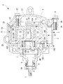
- FIG. 1 It is a longitudinal cross-sectional view of the stepped scroll compressor using the chip seal which concerns on one Embodiment of this invention. It is a perspective view of the fixed scroll and turning scroll of the scroll compressor shown in FIG. It is a perspective view of the fixed scroll and turning scroll of the scroll compressor shown in FIG. It is a schematic diagram which shows the installation state of the chip seal in the scroll compressor shown in FIG.
- FIG. 1 is a longitudinal sectional view of a scroll compressor according to the first embodiment of the present invention
- FIGS. 2A and 2B are perspective views of the fixed scroll and the orbiting scroll.
- the scroll compressor 1 has a housing 2 constituting an outer shell, and the housing 2 is configured by fastening and fixing a front housing 3 and a rear housing 4 together with bolts 5.
- the front housing 3 and the rear housing 4 are integrally formed with flanges 3A and 4A for fastening at equal intervals at a plurality of locations (for example, 4 locations) on the circumference, and the flanges 3A and 4A are bolted to each other.
- the front housing 3 and the rear housing 4 are integrally coupled by tightening with the bolt.
- a crankshaft (drive shaft) 6 is supported inside the front housing 3 via a main bearing 7 and a sub-bearing 8 so as to be rotatable around its axis L.
- One end side (left side in FIG. 1) of the crankshaft 6 is a small diameter shaft portion 6A, and the small diameter shaft portion 6A penetrates the front housing 3 and protrudes to the left side in FIG.
- the protruding portion of the small-diameter shaft portion 6A is provided with an electromagnetic clutch, a pulley (not shown) that receives power as is well known, and power is transmitted from a drive source such as an engine via a V-belt or the like.
- a mechanical seal (lip seal) 9 is installed between the main bearing 7 and the sub-bearing 8 and hermetically seals the inside of the housing 2 and the atmosphere.
- a large-diameter shaft portion 6B is provided on the other end side (right side in FIG. 1) of the crankshaft 6.
- the large-diameter shaft portion 6B has a crank pin that is eccentric from the axis L of the crankshaft 6 by a predetermined dimension.
- 6C is provided integrally.
- the crankshaft 6 is rotatably supported by the large-diameter shaft portion 6B and the small-diameter shaft portion 6A supported by the front housing 3 via the main bearing 7 and the sub-bearing 8.
- the crankpin 6C is connected to a turning scroll 15 to be described later via a drive bush 10, a cylindrical ring (floating bush) 11, and a drive bearing 12, and the turning scroll 15 is driven to turn by rotating the crankshaft 6. It is like that.
- the drive bush 10 is integrally provided with a balance weight 10 ⁇ / b> A for removing an unbalanced load generated when the orbiting scroll 15 is orbitally driven and is orbited together with the orbiting scroll 15. .
- the drive bush 10 is provided with a crank pin hole 10B into which the crank pin 6C is fitted at a position eccentric with respect to the center thereof. As a result, the drive bush 10 and the orbiting scroll 15 fitted to the crank pin 6C are rotated around the crank pin 6C under the gas compression reaction force, and a known follower that makes the orbiting radius of the orbiting scroll 15 variable.
- a crank mechanism is configured.
- a scroll compression mechanism 13 constituted by a pair of fixed scroll 14 and orbiting scroll 15 is incorporated.
- the fixed scroll 14 is composed of a fixed end plate 14A and a fixed spiral wrap 14B standing on the fixed end plate 14A, and the orbiting scroll 15 stands upright on the orbiting end plate 15A and the end plate 15A.
- the swirl spiral wrap 15B is incorporated in the housing 2.
- the fixed scroll 14 and the orbiting scroll 15 are at predetermined positions along the spiral direction of the tooth tip surfaces 14D and 15D and the tooth bottom surfaces 14E and 15E of the spiral wraps 14B and 15B.
- Steps 14F and 15F and 14G and 15G are provided, respectively.
- the tooth tip surfaces 14H, 15H on the outer peripheral side are higher in the direction of the axis L (referred to as higher tooth tip surfaces 14H, 15H).
- the inner peripheral tip surfaces 14I and 15I are low (referred to as lower tooth tip surfaces 14I and 15I), and the respective tip surfaces are flat surfaces having the same height. Yes.
- the tooth bases 14J and 15J on the outer peripheral side are low in the axis L direction (referred to as the lower tooth bases 14J and 15J), and the tooth bases 14K and 15K on the inner peripheral side are low. It is high (also referred to as high-order tooth bottom surfaces 14K and 15K), and each tooth bottom surface is a flat surface having the same height.
- the lap height in the outer peripheral side is made higher than the lap height in the inner peripheral side.
- the fixed scroll 14 and the orbiting scroll 15 are separated from each other by the orbiting radius ⁇ , and the phases of the spiral wraps 14B and 15B are shifted by 180 degrees to mesh with each other. , 15E with a clearance in the wrap height direction at room temperature.
- a plurality of pairs of compression chambers 16 limited by the end plates 14A and 15A and the spiral wraps 14B and 15B are located between the scrolls 14 and 15, with respect to the scroll center.
- the orbiting scroll 15 can smoothly turn around the fixed scroll 14.
- the compression chamber 16 has a circumferential height and a height direction of the spiral wraps 14B and 15B by making the height in the axis L direction higher than the height of the inner peripheral side on the outer peripheral side of the spiral wraps 14B and 15B.
- a scroll compression mechanism 13 capable of three-dimensional compression capable of compressing gas is formed on both sides. Tips for sealing tip seal surfaces formed between the tooth bottom surfaces 14E and 15E of the other scroll on the tooth tip surfaces 14D and 15D of the spiral wraps 14B and 15B of the fixed scroll 14 and the orbiting scroll 15, respectively.
- the seals 17 and 18 are installed by being fitted into grooves provided in the tooth tip surfaces 14D and 15D, respectively.
- the fixed scroll 14 is fixedly installed on the inner surface of the rear housing 4 via bolts 27. Further, as described above, the orbiting scroll 15 has a crank pin 6C provided on one end side of the crankshaft 6 with respect to the boss portion 15C provided on the back surface of the orbiting end plate 15A. It is connected via a (floating bush) 11 and a drive bearing 12 so as to be driven to rotate.
- the orbiting scroll 15 has a back surface of the orbiting end plate 15A supported on the thrust receiving surface 3B of the front housing 3, and a rotation prevention mechanism 19 provided between the thrust receiving surface 3B and the back surface of the orbiting end plate 15A.
- the rotation is driven around the fixed scroll 14 while being prevented from rotating.
- the rotation prevention mechanism 19 of this embodiment is incorporated in a pin hole on the front housing 3 side with respect to the inner peripheral surface of the rotation prevention ring 19A incorporated in a ring hole provided in the turning end plate 15A of the turning scroll 15.
- the rotation prevention pin 19B is a pin ring type rotation prevention mechanism 19 in which the rotation prevention pin 19B is slidably fitted.
- the fixed scroll 14 has a discharge port 14C that discharges the compressed refrigerant gas at the central portion of the fixed end plate 14A.
- the discharge port 14C is attached to the fixed end plate 14A via a retainer 20.
- a discharge valve 21 is installed.
- a sealing member 22 such as an O-ring is interposed on the back side of the fixed end plate 14A so as to be in close contact with the inner surface of the rear housing 4.
- a discharge chamber 23 partitioned from the space is formed.
- the internal space of the housing 2 excluding the discharge chamber 23 functions as the suction chamber 24.
- Refrigerant gas returning from the refrigeration cycle is sucked into the suction chamber 24 through the suction port 25 provided in the front housing 3, and the refrigerant gas is sucked into the compression chamber 16 through the suction chamber 24.
- a sealing material 26 such as an O-ring is interposed on the joint surface between the front housing 3 and the rear housing 4 to seal the suction chamber 24 formed in the housing 2 in an airtight manner against the atmosphere.
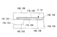
- FIG. 3 is a schematic view showing the installation state of the tip seals 17 and 18 provided on the high and low tooth tip surfaces 14H and 15H and 14I and 15I of the spiral wraps 14B and 15B of the fixed scroll 14 and the orbiting scroll 15. It is shown.
- the tip seals 17, 18 installed on the lower tooth tip surfaces 14I, 15I of the spiral wraps 14B, 15B of the fixed and orbiting scrolls 14, 15 are stepped at the ends.
- some of the stepped portions 14G and 15G provided on the bottom surfaces 14E and 15E of the counterpart scroll are overhanged and relatively swiveled. A state occurs.
- the surface side of the tip seals 17 and 18 is placed on the aforementioned polyphenylene sulfide (PPS), polyether ether ketone ( PEEK), polytetrafluoroethylene (PTFE), seal layers 17A and 18A composed of a rubber material such as fluororubber, or a composite material thereof, and strength layers 17B and 18B for suppressing bending on the back surface side.
- the chip seals 17 and 18 are used in which at least one strength layer made of a metal such as an aluminum alloy, a carbon sheet, or a high-strength resin material having a sufficiently small deflection than the surface-side seal material is provided. .
- the strength layers 17B and 18B are integrated with the back surfaces of the seal layers 17A and 18A by simultaneous molding or adhesion.
- the tip seals 17 and 18 have their end portions close to the root portions of the step portions 14F and 15F on the tooth tip surfaces 14D and 15D in the lower tooth tip surfaces 14I and 15I of the spiral wraps 14B and 15B. However, it may be installed on the higher tooth tip surfaces 14H and 15H.
- the revolving turning drive of the orbiting scroll 15 causes the refrigerant gas in the suction chamber 24 to be taken into the pair of compression chambers 16 formed on the outermost periphery in the radial direction.
- the compression chamber 16 is moved toward the center while the volume thereof is reduced in the circumferential direction and the lap height direction.
- the refrigerant gas is compressed, and when the compression chamber 16 reaches a position communicating with the discharge port 14C, the discharge reed valve 21 is pushed open.
- the compressed high-temperature and high-pressure gas is discharged into the discharge chamber 23 and is sent to the outside of the scroll compressor 1 through the discharge chamber 23.
- Tooth tip surfaces 14D and 15D higher tooth tip surfaces 14H and 15H and lower tooth tip surfaces 14I and 15I
- tooth bottom surfaces 14E and 15E lower tooth bottom surfaces 14J and 15J and higher tooth bottom surfaces 14K and 15K
- Tooth tip surfaces 14D and 15D higher tooth tip surfaces 14H and 15H and lower tooth tip surfaces 14I and 15I
- tooth bottom surfaces 14E and 15E lower tooth bottom surfaces 14J and 15J and higher tooth bottom surfaces 14K and 15K
- the tip seals 17 and 18 provided on the lower tooth tip surfaces 14I and 15I on the inner peripheral side of the stepped portions 14F and 15F are extended to the bases of the stepped portions 14F and 15F. Therefore, the installation range of the chip seals 17 and 18 can be expanded to enhance the sealing effect. Therefore, the stepped scroll compressor 1 can be further improved in performance by further reducing the amount of gas leakage and improving the compression efficiency.
- the tip seals 17 and 18 By extending the tip seals 17 and 18 to near the bases of the step portions 14F and 15F, the tip seals 17 and 18 overhang from the step portions 14G and 15G on the tooth bottom surfaces 14E and 15E side, and cantilevered. Although sliding in a state, the bending of the chip seals 17 and 18 can be suppressed by the strength layers 17B and 18B for suppressing the bending provided on the back surfaces of the sealing layers 17A and 18A. Therefore, even if the tip seals 17 and 18 are used in a cantilevered state, the risk of breakage caused by bending of the end portions can be eliminated.
- the strength layers 17B and 18B of the chip seals 17 and 18 are integrated on the back side of the seal layers 17A and 18A by simultaneous molding or adhesion, a single-layer structure which has been conventionally used in use. It can be used without changing the tip seal. Thereby, the use range can be expanded while maintaining the original functions of the chip seals 17 and 18.
- the seal layers 17A and 18A are made of a rubber material such as polyphenylene sulfide (PPS), polyether ether ketone (PEEK), polytetrafluoroethylene (PTFE), fluorine rubber, or a composite material thereof.
- PPS polyphenylene sulfide
- PEEK polyether ether ketone
- PTFE polytetrafluoroethylene
- fluorine rubber fluorine rubber
- a composite material thereof a composite material thereof.
- the strength layers 17B and 18B are made of a metal such as an aluminum alloy, a carbon sheet, or a high-strength resin material having a smaller deflection than the seal layer, a chip seal is formed by the seal layers 17A and 18 on the surface side.
- the wear resistance and slidability as 17 and 18 can be ensured, and the bending of the chip seal itself can be suppressed by the strength layers 17B and 18B provided on the back side thereof. Therefore, by suppressing the bending while
- the inner peripheral edge or outer peripheral edge of the spiral wrap is used to prevent the tip seal from being applied to the discharge port or the outer peripheral edge from coming off the end plate due to the turning of the orbiting scroll. I refrained from extending the tip seal to the end of the section.
- the tip seals 17 and 18 having the above-described configuration even if the tip seals 17 and 18 are applied to the discharge port or the outer peripheral end portion is detached from the end plate by the turning of the orbiting scroll, The risk of breakage caused by the bending of 18 can be eliminated.
- the installation range can be expanded to enhance the sealing effect, and the amount of gas leakage can be reduced and compressed.
- the efficiency can be improved and the scroll compressor can be improved.
- this invention is not limited to the invention concerning the said embodiment, In the range which does not deviate from the summary, it can change suitably.
- the example applied to the open type scroll compressor 1 has been described, but the present invention can also be applied to a hermetic type scroll compressor incorporating an electric motor as a power source.
- the example which provided strength layer 17B, 18B one layer was demonstrated, it cannot be overemphasized that it may provide in two or more layers separately.
Landscapes
- Engineering & Computer Science (AREA)
- Mechanical Engineering (AREA)
- General Engineering & Computer Science (AREA)
- Rotary Pumps (AREA)
Applications Claiming Priority (2)
| Application Number | Priority Date | Filing Date | Title |
|---|---|---|---|
| JP2012010026A JP2013148041A (ja) | 2012-01-20 | 2012-01-20 | チップシールおよびそれを用いたスクロール圧縮機 |
| JP2012-010026 | 2012-04-27 |
Publications (1)
| Publication Number | Publication Date |
|---|---|
| WO2013108866A1 true WO2013108866A1 (fr) | 2013-07-25 |
Family
ID=48799288
Family Applications (1)
| Application Number | Title | Priority Date | Filing Date |
|---|---|---|---|
| PCT/JP2013/050895 Ceased WO2013108866A1 (fr) | 2012-01-20 | 2013-01-18 | Joint d'embout et compresseur à carter spirale correspondant |
Country Status (2)
| Country | Link |
|---|---|
| JP (1) | JP2013148041A (fr) |
| WO (1) | WO2013108866A1 (fr) |
Families Citing this family (3)
| Publication number | Priority date | Publication date | Assignee | Title |
|---|---|---|---|---|
| JP6495611B2 (ja) * | 2014-10-16 | 2019-04-03 | 三菱重工サーマルシステムズ株式会社 | 圧縮機用スクロールの製造方法、製造装置 |
| WO2017208455A1 (fr) * | 2016-06-03 | 2017-12-07 | 三菱電機株式会社 | Compresseur à spirales |
| JP7755166B2 (ja) * | 2022-09-16 | 2025-10-16 | スターライト工業株式会社 | チップシール用樹脂組成物及びスクロール型冷媒圧縮機用チップシール |
Citations (3)
| Publication number | Priority date | Publication date | Assignee | Title |
|---|---|---|---|---|
| JPS5792U (fr) * | 1980-05-31 | 1982-01-05 | ||
| JP2002303281A (ja) * | 2001-02-02 | 2002-10-18 | Mitsubishi Heavy Ind Ltd | スクロール圧縮機 |
| WO2009038138A1 (fr) * | 2007-09-21 | 2009-03-26 | Mitsubishi Heavy Industries, Ltd. | Compresseur à spirale |
-
2012
- 2012-01-20 JP JP2012010026A patent/JP2013148041A/ja active Pending
-
2013
- 2013-01-18 WO PCT/JP2013/050895 patent/WO2013108866A1/fr not_active Ceased
Patent Citations (3)
| Publication number | Priority date | Publication date | Assignee | Title |
|---|---|---|---|---|
| JPS5792U (fr) * | 1980-05-31 | 1982-01-05 | ||
| JP2002303281A (ja) * | 2001-02-02 | 2002-10-18 | Mitsubishi Heavy Ind Ltd | スクロール圧縮機 |
| WO2009038138A1 (fr) * | 2007-09-21 | 2009-03-26 | Mitsubishi Heavy Industries, Ltd. | Compresseur à spirale |
Also Published As
| Publication number | Publication date |
|---|---|
| JP2013148041A (ja) | 2013-08-01 |
Similar Documents
| Publication | Publication Date | Title |
|---|---|---|
| JP5851851B2 (ja) | スクロール圧縮機 | |
| JP6180860B2 (ja) | スクロール圧縮機 | |
| WO2012005150A1 (fr) | Compresseur à spirale | |
| US11939977B2 (en) | Scroll compressor including fixed and orbiting scroll having stepped portions and a surface hardened treatment | |
| JP6207970B2 (ja) | スクロール型流体機械 | |
| WO2013108866A1 (fr) | Joint d'embout et compresseur à carter spirale correspondant | |
| WO2018012268A1 (fr) | Compresseur à spirale étagé et son procédé de conception | |
| WO2012153644A1 (fr) | Machine à fluide du type à volute | |
| JP5034975B2 (ja) | スクロール圧縮機 | |
| JP6906887B2 (ja) | スクロール流体機械 | |
| WO2010137468A1 (fr) | Compresseur à spirale | |
| JP6409910B1 (ja) | スクロール圧縮機 | |
| JP5175497B2 (ja) | スクロール式流体機械 | |
| JP5979974B2 (ja) | スクロール圧縮機およびその設計方法 | |
| GB2503728A (en) | Scroll compressor with circular wrap | |
| JP6599099B2 (ja) | スクロール流体機械 | |
| JP5791316B2 (ja) | スクロール型流体機械 | |
| CN217002269U (zh) | 一种co2涡旋压缩机的动盘柔性结构 | |
| JP7454786B2 (ja) | スクロール圧縮機 | |
| JP4635660B2 (ja) | スクロール圧縮機 | |
| US11976655B2 (en) | Scroll compressor | |
| WO2025079602A1 (fr) | Compresseur | |
| JP2010150966A (ja) | スクロール圧縮機 | |
| JP2012163114A (ja) | スクロール式流体機械 |
Legal Events
| Date | Code | Title | Description |
|---|---|---|---|
| 121 | Ep: the epo has been informed by wipo that ep was designated in this application |
Ref document number: 13738718 Country of ref document: EP Kind code of ref document: A1 |
|
| NENP | Non-entry into the national phase |
Ref country code: DE |
|
| 122 | Ep: pct application non-entry in european phase |
Ref document number: 13738718 Country of ref document: EP Kind code of ref document: A1 |