WO2013111202A1 - Dispositif d'affichage et procédé d'affichage - Google Patents
Dispositif d'affichage et procédé d'affichage Download PDFInfo
- Publication number
- WO2013111202A1 WO2013111202A1 PCT/JP2012/003961 JP2012003961W WO2013111202A1 WO 2013111202 A1 WO2013111202 A1 WO 2013111202A1 JP 2012003961 W JP2012003961 W JP 2012003961W WO 2013111202 A1 WO2013111202 A1 WO 2013111202A1
- Authority
- WO
- WIPO (PCT)
- Prior art keywords
- display
- area
- screen
- unit
- region
- Prior art date
- Legal status (The legal status is an assumption and is not a legal conclusion. Google has not performed a legal analysis and makes no representation as to the accuracy of the status listed.)
- Ceased
Links
Images




Classifications
-
- G—PHYSICS
- G06—COMPUTING OR CALCULATING; COUNTING
- G06F—ELECTRIC DIGITAL DATA PROCESSING
- G06F3/00—Input arrangements for transferring data to be processed into a form capable of being handled by the computer; Output arrangements for transferring data from processing unit to output unit, e.g. interface arrangements
- G06F3/01—Input arrangements or combined input and output arrangements for interaction between user and computer
- G06F3/048—Interaction techniques based on graphical user interfaces [GUI]
- G06F3/0487—Interaction techniques based on graphical user interfaces [GUI] using specific features provided by the input device, e.g. functions controlled by the rotation of a mouse with dual sensing arrangements, or of the nature of the input device, e.g. tap gestures based on pressure sensed by a digitiser
- G06F3/0488—Interaction techniques based on graphical user interfaces [GUI] using specific features provided by the input device, e.g. functions controlled by the rotation of a mouse with dual sensing arrangements, or of the nature of the input device, e.g. tap gestures based on pressure sensed by a digitiser using a touch-screen or digitiser, e.g. input of commands through traced gestures
- G06F3/04883—Interaction techniques based on graphical user interfaces [GUI] using specific features provided by the input device, e.g. functions controlled by the rotation of a mouse with dual sensing arrangements, or of the nature of the input device, e.g. tap gestures based on pressure sensed by a digitiser using a touch-screen or digitiser, e.g. input of commands through traced gestures for inputting data by handwriting, e.g. gesture or text
-
- G—PHYSICS
- G09—EDUCATION; CRYPTOGRAPHY; DISPLAY; ADVERTISING; SEALS
- G09G—ARRANGEMENTS OR CIRCUITS FOR CONTROL OF INDICATING DEVICES USING STATIC MEANS TO PRESENT VARIABLE INFORMATION
- G09G3/00—Control arrangements or circuits, of interest only in connection with visual indicators other than cathode-ray tubes
- G09G3/20—Control arrangements or circuits, of interest only in connection with visual indicators other than cathode-ray tubes for presentation of an assembly of a number of characters, e.g. a page, by composing the assembly by combination of individual elements arranged in a matrix no fixed position being assigned to or needed to be assigned to the individual characters or partial characters
-
- G—PHYSICS
- G06—COMPUTING OR CALCULATING; COUNTING
- G06F—ELECTRIC DIGITAL DATA PROCESSING
- G06F2203/00—Indexing scheme relating to G06F3/00 - G06F3/048
- G06F2203/048—Indexing scheme relating to G06F3/048
- G06F2203/04803—Split screen, i.e. subdividing the display area or the window area into separate subareas
-
- G—PHYSICS
- G09—EDUCATION; CRYPTOGRAPHY; DISPLAY; ADVERTISING; SEALS
- G09G—ARRANGEMENTS OR CIRCUITS FOR CONTROL OF INDICATING DEVICES USING STATIC MEANS TO PRESENT VARIABLE INFORMATION
- G09G2354/00—Aspects of interface with display user
-
- G—PHYSICS
- G09—EDUCATION; CRYPTOGRAPHY; DISPLAY; ADVERTISING; SEALS
- G09G—ARRANGEMENTS OR CIRCUITS FOR CONTROL OF INDICATING DEVICES USING STATIC MEANS TO PRESENT VARIABLE INFORMATION
- G09G3/00—Control arrangements or circuits, of interest only in connection with visual indicators other than cathode-ray tubes
- G09G3/20—Control arrangements or circuits, of interest only in connection with visual indicators other than cathode-ray tubes for presentation of an assembly of a number of characters, e.g. a page, by composing the assembly by combination of individual elements arranged in a matrix no fixed position being assigned to or needed to be assigned to the individual characters or partial characters
- G09G3/34—Control arrangements or circuits, of interest only in connection with visual indicators other than cathode-ray tubes for presentation of an assembly of a number of characters, e.g. a page, by composing the assembly by combination of individual elements arranged in a matrix no fixed position being assigned to or needed to be assigned to the individual characters or partial characters by control of light from an independent source
- G09G3/36—Control arrangements or circuits, of interest only in connection with visual indicators other than cathode-ray tubes for presentation of an assembly of a number of characters, e.g. a page, by composing the assembly by combination of individual elements arranged in a matrix no fixed position being assigned to or needed to be assigned to the individual characters or partial characters by control of light from an independent source using liquid crystals
- G09G3/3611—Control of matrices with row and column drivers
- G09G3/3648—Control of matrices with row and column drivers using an active matrix
- G09G3/3666—Control of matrices with row and column drivers using an active matrix with the matrix divided into sections
Definitions
- the present invention relates to a display device and a display method.
- Patent Document 1 a display device that divides a display screen by an intuitive operation by moving a finger on the display surface and displays a different screen in each divided area is known (for example, Patent Document 1).
- Patent Literature 1 when an icon displayed on the display screen is dragged with a finger in a predetermined direction, the display screen is divided based on the direction, and the divided display areas are different. It is disclosed that an image is displayed, and the screen can be divided by an intuitive operation such as finger movement.
- the present invention has been made to solve the above-described problem, and an object of the present invention is to provide a display device or the like that directs the direction of a display area newly generated by a screen division operation in the direction in which the operator exists. .
- a display device includes a display unit that displays an image and a position on the display unit that is designated by each of two or more fingers of an operator.
- the operation detection unit that detects a specified position and the operation detection unit detect that two or more specified positions are translated in the first region of the display unit, Based on two or more moving directions of the designated positions, the position of the second area, which is a newly generated area in the first area, and the display direction of the image displayed in the second area are determined.
- an operation analysis unit configured to display the image in the second region according to the position of the second region determined by the operation analysis unit and a display direction of the image displayed in the second region.
- a display control unit for controlling.
- the display device of the present invention it is possible to match the display direction of the divided screen with the direction in which the operator exists by an intuitive screen division operation.
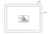
- FIG. 1 is a front view illustrating an example of an external configuration of a display device according to Embodiment 1.
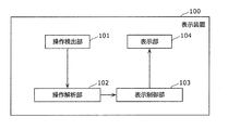
- FIG. FIG. 2 is a block diagram illustrating an example of a functional configuration of the display device according to the first embodiment.
- FIG. 3 is a flowchart illustrating processing of the operation analysis unit.
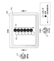
- FIG. 4 is a diagram illustrating an example of a display device before screen division according to the first embodiment.
- FIG. 5 is a diagram illustrating an example of the operation of the entrant according to the first embodiment.
- FIG. 6 is a diagram illustrating an example of a display device after screen division according to the first embodiment.
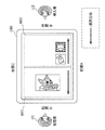
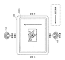
- FIG. 7 is a diagram illustrating an example of a display device before screen division according to the second embodiment.
- FIG. 8 is a diagram illustrating an example of the operation of the entrant according to the second embodiment.
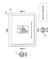
- FIG. 9 is a diagram illustrating an example of a display device after screen division according to the second embodiment.
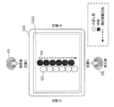
- FIG. 10 is a diagram illustrating a state of the display device before screen division according to the third embodiment.
- FIG. 11 is a diagram illustrating an example of the operation of the entrant according to the third embodiment.
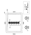
- FIG. 12 is a diagram illustrating an example of a display device after screen division according to the third embodiment.
- FIG. 13 is a diagram illustrating another example of the operation of the entrant according to the third embodiment.
- FIG. 14 is a diagram illustrating another example of the display device after screen division according to the third embodiment.
- Patent Document 1 allows intuitive screen division with a finger, it does not control the screen display direction after division. For example, when a plurality of people want to use a screen, there may occur a case where images displayed in each area after the screen division are not directed in an appropriate direction. In this case, setting by the operator such as changing the screen display direction after dividing the screen is required.
- the present invention has been made to solve the above-described problem, and an object of the present invention is to provide a display device or the like that directs the direction of a display area newly generated by a screen division operation in the direction in which the operator exists. .
- a display device includes a display unit that displays an image and a position on the display unit that is designated by each of two or more fingers of an operator.
- the operation detection unit that detects a specified position and the operation detection unit detect that two or more specified positions are translated in the first region of the display unit, Based on two or more moving directions of the designated positions, the position of the second area, which is a newly generated area in the first area, and the display direction of the image displayed in the second area are determined.
- an operation analysis unit configured to display the image in the second region according to the position of the second region determined by the operation analysis unit and a display direction of the image displayed in the second region.
- a display control unit for controlling.
- a new display area (second area) is added to the display area (first area) of the display device by an operator who intends to newly use the display apparatus by operating his / her two or more fingers. ) Can be created.
- the display device manipulates the display direction of the new display area based on the relative positional relationship between the designated positions caused by the difference in the finger length of the operator and the moving direction of the designated position. Can be directed in the direction where the person exists. Therefore, the direction of the display area newly generated by the screen division operation can be directed to the direction in which the operator exists without setting the screen display direction.
- the operation analysis unit estimates the operator's direction viewed from the display device based on an arrangement direction and a movement direction of the two or more designated positions, and displays the direction in the second region.
- the display direction of the image to be displayed may be determined.
- the display device in the operation of the operator who intends to newly use the display device, the display device exists based on the arrangement direction and the moving direction of the contact positions of two or more fingers of the operator. Estimate the direction. Then, the display direction of the new display area (second area) is determined so as to have a natural orientation when used by an operator existing in the estimated direction. Therefore, the direction of the display area newly generated by the screen division operation can be directed to the direction in which the operator exists.
- the operation analysis unit estimates the direction of the operator as viewed from the display device based on an arrangement direction and a movement direction of the two or more designated positions, and the first region is the position of the designated position.
- An area closer to the operator may be determined as the position of the second area among areas formed by being divided by lines corresponding to the trajectory.
- the operator can use, as his / her own display area, a display area formed after the division operation. Therefore, a display area newly generated by the screen division operation is formed near the operator, and the operator can use the display area without performing an operation such as separate position adjustment.
- the display control unit displays the image displayed in the first area in a third area that is an area in the first area and not included in the second area, An image for the operator may be displayed in the second area.
- an operation screen for a new operator can be displayed in a new display area (second area) formed near the new operator.
- the contents displayed on the display device (first area) used by the user are displayed in the area (third area) near the user remaining after the new display area is formed.
- the user can continue to view the display content for himself / herself near the user. Therefore, the user and the new operator can browse the display area for themselves after forming a new display area.
- the display control unit may determine the display direction of the image displayed in the third area as a direction that matches the display direction of the image displayed in the first area.
- the user can continue to use the display contents that the user has displayed on the display device (first area) before the new operator appears in the display direction. Therefore, the user can continue to use the display area for himself / herself after forming a new display area.
- the display control unit may display the image displayed in the first area in at least one of the second area and the third area.
- the area near the user (third area) Can be displayed.
- the display content that the user has displayed on the display device (first area) before the new operator appears is divided and then displayed in the area near the new operator (second area). Can be displayed. Either method can be used depending on the selection of the user and the new operator.
- the operation analysis unit detects that the two designated positions are translated in the first region
- the operation position of the two designated positions, the arrangement direction of the two designated positions, and The position of the second area and the display direction of the image displayed in the second area may be determined based on the moving direction.
- the display method according to one aspect of the present invention is a display method in a display device including a display unit that displays an image, at a position on the display unit specified by each of two or more fingers of an operator.
- the operation detecting step for detecting a specified position and in the operation detecting step, if it is detected that two or more specified positions are translated in the first region of the display unit, the two or more specified positions are detected.
- the position of the second area which is a newly generated area in the first area, and the display direction of the image displayed in the second area
- An operation analysis step for determining the image, and an image is displayed in the second region in accordance with the position of the second region determined in the operation analysis step and the display direction of the image displayed in the second region.
- a display control step of controlling the display unit In including a display control step of controlling the display unit.
- the display method has the same effect as the display device.
- a program that is one embodiment of the present invention causes a computer to execute the above display method.
- the computer has the same effect as the display device.
- FIG. 1 is a front view showing an example of an external configuration of the display device according to the first embodiment.
- FIG. 2 is a block diagram illustrating an example of a functional configuration of the display device according to the first embodiment.
- the display device 100 includes an operation detection unit 101, an operation analysis unit 102, a display control unit 103, and a display unit 104.
- the operation detection unit 101 detects contact between the screen surface of the display device 100 and the operator's finger.
- the operation detection unit 101 generates detection information such as coordinate data of a contact point when the operator's finger contacts the screen surface, and notifies the operation analysis unit 102 of the detection information.
- the operation detection unit 101 is realized by a touch panel, for example.
- the object detected by the operation detection unit 101 is not limited to direct contact between the screen surface and the operator's finger, but the operation performed by the operator's finger is indirectly transmitted to the screen surface via an object such as a stylus. The contact between the screen surface and the object may be possible.
- the operation analysis unit 102 analyzes the number of contact points between the operator's finger and the screen surface, the moving direction or moving distance in the contact state, and the like from the detection information generated by the operation detecting unit 101. Further, the screen division position and the image display direction after division are determined from the analysis result.
- the display control unit 103 creates display data based on information such as the screen division position determined by the operation analysis unit 102 and the image display direction after division, and transmits the display data to the display unit 104.
- the display unit 104 displays an image based on the image display information from the display control unit 103.
- a touch panel (not shown), which is the operation detection unit 101, is disposed on the upper portion of the display unit 104.
- a specific example of the display device 100 is a tablet terminal, a large-screen touch panel display, a smartphone, or a mobile phone terminal.
- FIG. 3 is a flowchart showing the operation of the operation analysis unit 102.
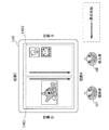
- FIG. 4 is a diagram illustrating a state of the display device before screen division according to the first embodiment.
- FIG. 5 is a diagram illustrating an example of the operation of the entrant according to the first embodiment.
- FIG. 6 is a diagram illustrating a state after screen division according to the first embodiment.
- the operator designates the boundary line of the division by an intuitive operation of sliding the finger on the display unit along the line to be the boundary line of the division.
- the operation of sliding is natural.
- a right-handed operator naturally performs an operation of sliding his / her finger from the left to the right on the screen as viewed from the operator.
- the dominant hand of the operator may be set in advance. Alternatively, the operator may be identified by user authentication or the like, and the dominant hand may be determined using predetermined operator dominant hand information.
- the image display direction is a direction from the center of the screen toward the position D.
- the image display direction is a direction from the top to the bottom of the image (display contents).
- the entrant U2 enters the position B as shown in FIG.
- the entrant U2 divides the screen by bringing two fingers (for example, an index finger and a middle finger) into contact with the position A and moving them toward the position C while keeping the two fingers in contact.
- the white circle indicates the contact position of the index finger
- the black circle indicates the contact position of the middle finger.
- the operation analysis unit 102 clears the operation start position when the display device 100 is activated by turning on the power (step S301).
- the operation detection unit 101 detects the operation of the participant, the operation detection unit 101 generates contact point detection information (for example, coordinate data) on the screen surface and notifies the operation analysis unit 102 of the detection information.
- the operation analysis unit 102 analyzes the number of contact points on the screen surface (how many points have been touched) from the notified detection information.
- the operation analysis unit 102 is in a waiting state until detection information is notified from the operation detection unit 101.
- step S303 determines whether or not the number of contact points is two (step S303). If it is determined that the number of contact points is two (Y in step S303), the operation analysis unit 102 determines whether or not the operation start position is held (step S304). If it is determined in step S304 that the operation start position is not held (N in step S304), the operation analysis unit 102 holds the two detected contact points as the operation start position (step S310). The process returns to step S302.
- step S303 determines that the number of contact points is not two (N in step S303)
- the operation analysis unit 102 determines that a normal operation on the display device is performed instead of the screen division operation, and the normal operation is performed.
- step S309 the process returns to step S301.
- the operation analysis unit 102 determines in step S303 that the number of contact points is 0, the operation analysis unit 102 determines that the division operation has been completed halfway.
- step S304 determines whether or not the two detected contact points are translated (step S304).
- Step S305 the operation analysis unit 102 determines that the movement is parallel when the contact point detected this time is on the line connecting the operation start position and the previous detection point. In this determination, the contact point detected this time does not necessarily exist on the line. That is, if the position is within a predetermined distance from the line connecting the operation start position and the previous detection point, it may be determined that the movement is parallel. Further, if the angle between the line connecting the operation start position and the previous detection point and the line connecting the operation start position and the current detection point is within a predetermined angle, it is determined that the movement is parallel. You may do it. Further, the operation analysis unit 102 may determine that the translation has been performed when there is no previous detection point.
- step S305 If the operation analysis unit 102 determines in step S305 that the two detected contact points are not translated from the operation start position (N in step S305), the operation analysis unit 102 performs a normal pinch-out instead of the screen division operation. After performing the normal operation analysis process (step S309), the process returns to step S301.
- step S305 when the operation analysis unit 102 determines that the two points are moving in parallel (Y in step S305), the parallel movement distance from the start position to the detected contact point is set in advance. Comparison with a predetermined distance is performed (step S306). If the operation analysis unit 102 determines in step S306 that the parallel movement distance is shorter than the preset default distance (N in step S306), the operation analysis unit 102 returns to step S302.
- step S306 determines in step S306 that the translated distance is greater than or equal to the predetermined distance (Y in step S306), the operation analysis unit 102 determines that the screen division operation has been completed, and the position of the participant U2 The identification is performed (step S307).
- the operation analysis unit 102 determines the position of the entrant U2 with respect to the display device 100.
- the reason why the two translation directions are from the position A to the position C is that the entrant U2 enters the position B and translates the finger from left to right (position A to position C). Or the entry U2 enters the position C and translates the finger from top to bottom (position A to position C). It is determined in any of the above cases by the processing described below.
- the operation analysis unit 102 analyzes the positional relationship (alignment direction) between the operation start points P1 and Q1 in FIG.
- the operation analysis unit 102 uses the fact that the lengths of the index finger and the middle finger are different, and when the left point is closer to the candidate position than the right point as seen from the candidate position (candidate of the position where the entrant entered), It is determined that the candidate position is the entry position. A specific determination process will be described below.
- the candidate position is set to position B, and the determination is performed as follows.
- Q1 is the index finger
- P1 is the middle finger, that is, the white circle in FIG. 5 is the index finger
- the black circle is the contact position of the middle finger.
- the determination is as follows. Since the left point Q1 is farther from the candidate position C than the right point P1 when viewed from the position C, it is determined that the position where the entrant U2 has entered is not the position C. Therefore, it is consistent with the determination when the candidate position is the position B.
- the operation analysis unit 102 analyzes the relationship between the entry position of the identified participant U2 and the direction in which the finger is moved for screen division, and the screen division direction and the division after division.
- the image display direction on the screen is determined and notified to the display control unit 103 as image display direction information (step S308).
- the operation analysis unit 102 divides the display screen into the divided screen 601 on the position D side and the divided screen on the position B side when the screen dividing direction (finger moving direction) is from the position A to the position C. It is decided to divide into the screen 602.
- the operation analysis unit 102 since the entry position is the position B, the operation analysis unit 102 has a divided screen 602 on the side of the position B that is closer to the entry position after the division, and the screen that was being used before the division is It is determined to be displayed on the divided screen 601 at the position D.
- the content displayed on the divided screen 601 may be a reduced content of the screen before the division, or may be the same size as the conventional one.
- a screen for entrants may be displayed on the divided screen 602.
- the screen displayed on the divided screen 602 may be the same as the content of the screen before the division.
- the operation analysis unit 102 determines the entry position and the image display direction of the divided divided screen, the entry position is the position B. Therefore, the image display direction when displaying in the new area is from the position D to the position B. It is determined that the image display direction to be displayed on the divided screen 601 that displays the screen that was being used is the direction from position B to position D. The operation analysis unit 102 notifies the display control unit 103 of the determined division direction and the image display direction on the divided screen.
- the display control unit 103 controls the display unit 104 based on the division direction and the image display direction information notified from the operation analysis unit 102, and as shown in FIG. Each screen is divided into two. The screen is displayed in the direction from position B to position D on the divided screen 601 on the position D side, and the screen is displayed in the direction from position D to position B on the divided screen 602 on the position B side.
- the entrant simply splits the screen intuitively using two fingers, and the two positions of the moving direction and the contact start point of the two fingers.
- the entry position of the entrant can be specified from the relationship, and the screen can be displayed in an appropriate direction after dividing the screen.
- the expression of dividing the screen is used. However, it can be expressed that a new second area is generated in the first area of the display unit.
- an operator who intends to newly use the display device operates the display region ( A new display area (second area) can be created in the first area).
- the display device manipulates the display direction of the new display area based on the relative positional relationship between the designated positions caused by the difference in the finger length of the operator and the moving direction of the designated position. Can be directed in the direction where the person exists. Therefore, the direction of the display area newly generated by the screen division operation can be directed to the direction in which the operator exists without setting the screen display direction.
- the display device determines the direction in which the operator exists based on the arrangement direction and the moving direction of the contact positions of two or more fingers of the operator. presume. Then, the display direction of the new display area (second area) is determined so as to have a natural orientation when used by an operator existing in the estimated direction. Therefore, the direction of the display area newly generated by the screen division operation can be directed to the direction in which the operator exists.
- the operator can use the display area formed after the division operation as the display area closer to the operator. Therefore, a display area newly generated by the screen division operation is formed near the operator, and the operator can use the display area without performing an operation such as separate position adjustment.
- an operation screen for a new operator can be displayed in a new display area (second area) formed near the new operator.
- the contents displayed on the display device (first area) used by the user are displayed in the area (third area) near the user remaining after the new display area is formed.
- the user can continue to view the display content for himself / herself near the user. Therefore, the user and the new operator can browse the display area for themselves after forming a new display area.
- the display contents that the user has displayed on the display device (first area) before the new operator appears can be used by the user in the display direction. Therefore, the user can continue to use the display area for himself / herself after forming a new display area.
- the display contents that the user has displayed on the display device (first area) before the new operator appears are displayed in the area (third area) near the user after the division operation. be able to.
- the display content that the user has displayed on the display device (first area) before the new operator appears is divided and then displayed in the area near the new operator (second area). Can be displayed. Either method can be used depending on the selection of the user and the new operator.
- the screen can be divided and the display direction of a new screen image can be determined by the operation of the operator by moving the two fingers in parallel.
- the user U3 exists at the position D, and the screen direction is in the direction of the position D.
- the entrant U4 enters the position A, and two fingers (for example, the index finger and the middle finger) are brought into contact with the vicinity of the position C and moved toward the position A.
- the operation detection unit 101 performs the same processing as in the first embodiment, generates detection information when two fingers move in contact with the screen surface, and notifies the operation analysis unit 102 of the detection information.
- the operation analysis unit 102 specifies the position of the entrant based on the detection information.
- the operation analysis unit 102 determines the position of the entrant U4 with respect to the display device 100.
- the translation direction of the two points is the direction from the position C to the position A because the entrant U4 enters the position D and translates the finger from left to right (position C to position A). Or the entrant U4 enters the position A and translates the finger from top to bottom (position C to position A). It is determined in any of the above cases by the processing described below.
- the operation analysis unit 102 analyzes the positional relationship between the start point P2 and the start point Q2 in FIG.
- the operation analysis unit 102 uses the difference between the lengths of the index finger and the middle finger, and determines that the candidate position is the entry position when the left point is closer to the candidate position than the right point when viewed from the candidate position. To do. A specific determination process will be described below.
- the determination is as follows. Since the left point P2 is farther from the candidate position D than the right point Q2 when viewed from the position D, it is determined that the position where the entrant U4 has entered is not the position D. Therefore, this is consistent with the determination when the candidate position is position A.
- the operation analysis unit 102 analyzes the relationship between the entry position of the identified participant U4 and the direction in which the finger is moved for screen division, and the screen division direction and division after division.
- the image display direction on the screen is determined and notified to the display control unit 103 as image display direction information.
- the operation analysis unit 102 divides the display screen into the divided screen 901 on the position D side and the divided screen on the position B side when the screen dividing direction (finger moving direction) is from the position C to the position A. It is divided into a screen 902. Since the entry position is position A, the operation analysis unit 102 displays the new area after the division on the divided screen 902 on the position B side, and displays the conventional screen that was in use on the divided screen 901 at the position D. To decide.
- the operation analysis unit 102 determines the entry position and the position of the new area after the division, the entry position is the position A, so the image display direction when displaying in the new area is the direction from the position C to the position A. It is determined that the image display direction to be displayed on the divided screen 901 that displays the screen being used is the direction from position B to position D.
- the operation analysis unit 102 notifies the display control unit 103 of the determined division direction and the image display direction on the divided screen.
- the display control unit 103 controls the display unit 104 based on the division direction and the image display direction information notified from the operation analysis unit 102, and as shown in FIG. Each screen is divided into two. Then, the screen is displayed in the direction from position B to position D on the divided screen 901 on the position D side, and the screen is displayed in the direction from position C to position A on the divided screen 902 on the position B side.
- the entrant simply splits the screen intuitively using two fingers, and the two positions of the moving direction and the contact start point of the two fingers.
- the entry position of the entrant can be specified from the relationship, and the screen can be displayed in an appropriate direction after dividing the screen.
- the entrant demonstrated the case where it entered into the position A with respect to the user who exists in the position D, the same process is performed also when it enters into the position C, and it divides
- the finger position is the position where the index finger and the middle finger are opposite, the finger direction is from position A to position C, and the image display direction of the divided divided screen 902 is from position A to position C. It becomes.
- the position A since the user exists at the position D, the position A may be determined without considering the case where the position of the entrant is the position D.
- the image display direction of the divided display area is the same as the screen of the user.
- the image display direction of the divided screen 902 is the direction from the same position B to the position D as the divided screen 901.
- the entry U6 has entered the position A, so that the screen is positioned.
- An example of dividing from C to position A will be described.
- a case is considered in which the entrant U6 performs a split operation using two fingers, the index finger and the middle finger.
- the screen direction is in the direction of the position C as shown in FIG.
- the entrant enters position A, touches two fingers (for example, index finger and middle finger) near position C, and keeps the two fingers in contact with position A.
- the white circle indicates the contact position of the index finger
- the black circle indicates the contact position of the middle finger.
- the operation detection unit 101 performs the same processing as in the first embodiment, generates detection information when two fingers move in contact with the screen surface, and notifies the operation analysis unit 102 of the detection information.
- the operation analysis unit 102 specifies the position of the entrant based on the detection information.
- the operation analysis unit 102 determines the position of the entrant U6 with respect to the display device 100.
- the two translation directions are from the position C to the position A because the entrant U6 enters the position D and translates the finger from left to right (position C to position A). Or the entrant U6 enters the position A and translates the finger from top to bottom (position C to position A). It is determined in any of the above cases by the processing described below.
- the operation analysis unit 102 analyzes the positional relationship between the start point P3 and the start point Q3 in FIG.
- the operation analysis unit 102 uses the difference between the lengths of the index finger and the middle finger, and determines that the candidate position is the entry position when the left point is closer to the candidate position than the right point when viewed from the candidate position. To do. A specific determination process will be described below.
- the candidate position is set to position A, and determination is performed as follows.
- P3 is the middle finger
- Q3 is the index finger, that is, the white circle in FIG. 11 is the index finger
- the black circle is the middle finger contact position.
- the determination is as follows. Since the left point P3 is farther from the candidate position D than the right point Q3 when viewed from the position D, the position where the entrant U6 has entered is determined not to be the position D. Therefore, this is consistent with the determination when the candidate position is position A.
- the operation analysis unit 102 analyzes the relationship between the entry position of the identified participant U6 and the direction in which the finger has been moved for screen division, and the screen division direction and the post-division The image display direction in the divided screen is determined and notified to the display control unit 103 as image display direction information.
- the operation analysis unit 102 divides the display screen into the divided screen 1201 on the position D side and the divided screen on the position B side when the screen dividing direction (finger moving direction) is from the position C to the position A. It is divided into a screen 1202. In this case, the operation analysis unit 102 determines that the new area after the division is the divided screen 1202 on the position B side, and the conventional screen that has been used is displayed on the divided screen 1201 on the position D side. It may be determined that the new area after the division is the divided screen 1201 and the conventional screen that has been used is displayed on the divided screen 1202.
- the operation analysis unit 102 determines the entry position and the position of the new area after the division, the entry position is the position A, so the image display direction when displaying in the new area is the direction from the position C to the position A. It is determined that the image display direction to be displayed on the divided screen 1201 that displays the screen that was being used is the direction from position A to position C.
- the operation analysis unit 102 notifies the display control unit 103 of the determined division direction and the image display direction on the divided screen.
- the display control unit 103 controls the display unit 104 based on the information on the division direction and the image display direction notified from the operation analysis unit 102, and the screen is displayed on the positions D and B as shown in FIG. Is divided into two. After the division, the screen is displayed from the position A to the position C on the divided screen 1201 on the position D side, and the screen is displayed from the position C to the position A on the divided screen 1202 on the position B side.
- the entrant U8 can enter the position A on the same side as the user U7 with respect to the display device 100 (display area 1301). In this case, the entrant U8 divides the screen from the position C to the position A.
- the operation of the participant's finger and the process for recognizing the operation are the same as described above.
- a new area for the entrant U8 is formed as shown in FIG. That is, the display screen is divided into a divided screen 1401 on the position D side and a divided screen 1402 on the position B side.
- the image display direction of the screen 1402 after the screen is the direction of the position of the entrant U8.
- which of the split screen 1401 on the position D side and the split screen on the position B side is to display the screen for the user (where the screen for the entrant is to be displayed). May be set in advance and determined according to the setting.
- the entrant uses only two fingers to intuitively divide the screen and specifies the entry position of the entrant from the positional relationship between the moving direction and the contact start point of the two fingers.
- the screen can be displayed in an appropriate direction after the screen is divided.
- the case where two fingers of the index finger and the middle finger are used as the fingers to be used for dividing the screen has been described, but the other two fingers or two or more fingers are used. May be.
- the position of the participant can be specified from the positional relationship of each finger.
- the position of the participant may be specified from the positions of two of the two or more fingers.
- the display device in each embodiment may be a device having a display unit capable of displaying an image.
- each component may be configured by dedicated hardware or may be realized by executing a software program suitable for each component.
- Each component may be realized by a program execution unit such as a CPU or a processor reading and executing a software program recorded on a recording medium such as a hard disk or a semiconductor memory.
- the software that realizes the image decoding apparatus of each of the above embodiments is the following program.
- this program is a display method in a display device including a display unit for displaying an image on a computer, and a designated position that is a position on the display unit designated by each of two or more fingers of an operator.
- the operation detecting step to detect and the operation detecting step when it is detected that two or more specified positions are translated in the first region of the display unit, two or more specified positions, 2
- An image is displayed in the second area according to the analysis step, the position of the second area determined in the operation analysis step, and the display direction of the image displayed in the second area.
- a display control step of controlling the display unit so.
- the display device of the present invention is useful when a plurality of operators use one terminal.
Landscapes
- Engineering & Computer Science (AREA)
- Theoretical Computer Science (AREA)
- Physics & Mathematics (AREA)
- General Physics & Mathematics (AREA)
- General Engineering & Computer Science (AREA)
- Computer Hardware Design (AREA)
- Human Computer Interaction (AREA)
- User Interface Of Digital Computer (AREA)
- Position Input By Displaying (AREA)
Abstract
La présente invention concerne un dispositif d'affichage (100), l'orientation d'une zone d'affichage nouvellement créée par une opération de division de l'écran étant orientée dans la direction où se trouve l'opérateur. L'invention est pourvue des éléments suivants : une unité d'affichage (104) qui affiche une image ; une unité de détection d'opération (101) qui détecte un emplacement désigné correspondant à l'emplacement de l'unité d'affichage (104) ayant été désigné par chacun de deux doigts ou plus d'un opérateur ; une unité d'analyse d'opération (102) qui, si l'unité de détection d'opération (101) a détecté que dans une première zone de l'unité d'affichage (104), deux emplacements désignés ou plus sont en cours de translation latérale, en fonction desdits deux emplacements désignés ou plus et du sens de translation desdits deux emplacements désignés ou plus, détermine la position d'une seconde zone qui est une zone nouvellement créée à l'intérieur de la première zone, et le sens d'affichage de l'image à afficher dans la seconde zone ; et une unité de commande d'affichage (103) qui, en fonction de la position de la seconde zone et du sens d'affichage de l'image à afficher dans la seconde zone qui ont été déterminés par l'unité d'analyse d'opération (102), commande à l'unité d'affichage (104) d'afficher l'image dans la seconde zone.
Priority Applications (2)
| Application Number | Priority Date | Filing Date | Title |
|---|---|---|---|
| JP2012548265A JP5248715B1 (ja) | 2012-01-27 | 2012-06-18 | 表示装置および表示方法 |
| US13/793,484 US8963867B2 (en) | 2012-01-27 | 2013-03-11 | Display device and display method |
Applications Claiming Priority (2)
| Application Number | Priority Date | Filing Date | Title |
|---|---|---|---|
| JP2012-015183 | 2012-01-27 | ||
| JP2012015183 | 2012-01-27 |
Related Child Applications (1)
| Application Number | Title | Priority Date | Filing Date |
|---|---|---|---|
| US13/793,484 Continuation US8963867B2 (en) | 2012-01-27 | 2013-03-11 | Display device and display method |
Publications (1)
| Publication Number | Publication Date |
|---|---|
| WO2013111202A1 true WO2013111202A1 (fr) | 2013-08-01 |
Family
ID=48872981
Family Applications (1)
| Application Number | Title | Priority Date | Filing Date |
|---|---|---|---|
| PCT/JP2012/003961 Ceased WO2013111202A1 (fr) | 2012-01-27 | 2012-06-18 | Dispositif d'affichage et procédé d'affichage |
Country Status (2)
| Country | Link |
|---|---|
| JP (1) | JP5248715B1 (fr) |
| WO (1) | WO2013111202A1 (fr) |
Cited By (1)
| Publication number | Priority date | Publication date | Assignee | Title |
|---|---|---|---|---|
| JP2016161866A (ja) * | 2015-03-04 | 2016-09-05 | セイコーエプソン株式会社 | 表示装置および表示制御方法 |
Citations (2)
| Publication number | Priority date | Publication date | Assignee | Title |
|---|---|---|---|---|
| JP2007257220A (ja) * | 2006-03-22 | 2007-10-04 | Matsushita Electric Ind Co Ltd | 表示装置 |
| JP2010097473A (ja) * | 2008-10-17 | 2010-04-30 | Sony Corp | 表示装置、表示方法及びプログラム |
-
2012
- 2012-06-18 WO PCT/JP2012/003961 patent/WO2013111202A1/fr not_active Ceased
- 2012-06-18 JP JP2012548265A patent/JP5248715B1/ja active Active
Patent Citations (2)
| Publication number | Priority date | Publication date | Assignee | Title |
|---|---|---|---|---|
| JP2007257220A (ja) * | 2006-03-22 | 2007-10-04 | Matsushita Electric Ind Co Ltd | 表示装置 |
| JP2010097473A (ja) * | 2008-10-17 | 2010-04-30 | Sony Corp | 表示装置、表示方法及びプログラム |
Cited By (1)
| Publication number | Priority date | Publication date | Assignee | Title |
|---|---|---|---|---|
| JP2016161866A (ja) * | 2015-03-04 | 2016-09-05 | セイコーエプソン株式会社 | 表示装置および表示制御方法 |
Also Published As
| Publication number | Publication date |
|---|---|
| JP5248715B1 (ja) | 2013-07-31 |
| JPWO2013111202A1 (ja) | 2015-05-11 |
Similar Documents
| Publication | Publication Date | Title |
|---|---|---|
| US9652146B2 (en) | Ergonomic motion detection for receiving character input to electronic devices | |
| JP6215534B2 (ja) | 情報処理装置及び情報処理方法、並びにコンピューター・プログラム | |
| JP4734435B2 (ja) | タッチパネル式ディスプレイを持った携帯型ゲーム装置 | |
| US8686946B2 (en) | Dual-mode input device | |
| US8963867B2 (en) | Display device and display method | |
| EP2474896A2 (fr) | Appareil et procédé de traitement d'informations et programme informatique | |
| CN103941995B (zh) | 信息处理装置、信息处理方法 | |
| CN103488296A (zh) | 体感交互手势控制方法及装置 | |
| US9778780B2 (en) | Method for providing user interface using multi-point touch and apparatus for same | |
| KR20140047515A (ko) | 데이터 입력을 위한 전자 장치 및 그 운용 방법 | |
| KR102205283B1 (ko) | 적어도 하나의 어플리케이션을 실행하는 전자 장치 및 그 제어 방법 | |
| TW200941303A (en) | Multi-object direction touch selection method and device, electronic device, computer accessible recording media and computer program product | |
| CN103080885B (zh) | 用于编辑对象布局的方法和装置 | |
| JP5248715B1 (ja) | 表示装置および表示方法 | |
| CN101546231B (zh) | 多物件方向触控选取方法及装置 | |
| KR102067295B1 (ko) | 전자 장치, 표시 제어 방법, 및 기록 매체 | |
| KR101436588B1 (ko) | 멀티 포인트 터치를 이용한 사용자 인터페이스 제공 방법 및 이를 위한 장치 | |
| JP5769841B2 (ja) | タッチパネル式ディスプレイを持った携帯型ゲーム装置 | |
| JP2018023792A (ja) | ゲーム装置及びプログラム | |
| JP6126639B2 (ja) | タッチパネル式ディスプレイを持った携帯型ゲーム装置及びゲームプログラム。 | |
| JP5523381B2 (ja) | タッチパネル式ディスプレイを持った携帯型ゲーム装置 | |
| TWI677818B (zh) | 電子裝置及其控制方法 | |
| JP6204414B2 (ja) | ゲーム装置及びプログラム | |
| JP5769765B2 (ja) | タッチパネル式ディスプレイを持った携帯型ゲーム装置 | |
| JP6036598B2 (ja) | 情報処理装置及び情報処理プログラム |
Legal Events
| Date | Code | Title | Description |
|---|---|---|---|
| ENP | Entry into the national phase |
Ref document number: 2012548265 Country of ref document: JP Kind code of ref document: A |
|
| 121 | Ep: the epo has been informed by wipo that ep was designated in this application |
Ref document number: 12866785 Country of ref document: EP Kind code of ref document: A1 |
|
| NENP | Non-entry into the national phase |
Ref country code: DE |
|
| 122 | Ep: pct application non-entry in european phase |
Ref document number: 12866785 Country of ref document: EP Kind code of ref document: A1 |