WO2013111331A1 - Système informatique - Google Patents
Système informatique Download PDFInfo
- Publication number
- WO2013111331A1 WO2013111331A1 PCT/JP2012/051853 JP2012051853W WO2013111331A1 WO 2013111331 A1 WO2013111331 A1 WO 2013111331A1 JP 2012051853 W JP2012051853 W JP 2012051853W WO 2013111331 A1 WO2013111331 A1 WO 2013111331A1
- Authority
- WO
- WIPO (PCT)
- Prior art keywords
- resource
- condition
- storage
- storage resource
- information
- Prior art date
- Legal status (The legal status is an assumption and is not a legal conclusion. Google has not performed a legal analysis and makes no representation as to the accuracy of the status listed.)
- Ceased
Links
Images















Classifications
-
- G—PHYSICS
- G06—COMPUTING OR CALCULATING; COUNTING
- G06F—ELECTRIC DIGITAL DATA PROCESSING
- G06F3/00—Input arrangements for transferring data to be processed into a form capable of being handled by the computer; Output arrangements for transferring data from processing unit to output unit, e.g. interface arrangements
- G06F3/06—Digital input from, or digital output to, record carriers, e.g. RAID, emulated record carriers or networked record carriers
- G06F3/0601—Interfaces specially adapted for storage systems
- G06F3/0602—Interfaces specially adapted for storage systems specifically adapted to achieve a particular effect
- G06F3/0604—Improving or facilitating administration, e.g. storage management
- G06F3/0605—Improving or facilitating administration, e.g. storage management by facilitating the interaction with a user or administrator
-
- G—PHYSICS
- G06—COMPUTING OR CALCULATING; COUNTING
- G06F—ELECTRIC DIGITAL DATA PROCESSING
- G06F11/00—Error detection; Error correction; Monitoring
- G06F11/008—Reliability or availability analysis
-
- G—PHYSICS
- G06—COMPUTING OR CALCULATING; COUNTING
- G06F—ELECTRIC DIGITAL DATA PROCESSING
- G06F3/00—Input arrangements for transferring data to be processed into a form capable of being handled by the computer; Output arrangements for transferring data from processing unit to output unit, e.g. interface arrangements
- G06F3/06—Digital input from, or digital output to, record carriers, e.g. RAID, emulated record carriers or networked record carriers
- G06F3/0601—Interfaces specially adapted for storage systems
- G06F3/0628—Interfaces specially adapted for storage systems making use of a particular technique
- G06F3/0629—Configuration or reconfiguration of storage systems
- G06F3/0631—Configuration or reconfiguration of storage systems by allocating resources to storage systems
-
- G—PHYSICS
- G06—COMPUTING OR CALCULATING; COUNTING
- G06F—ELECTRIC DIGITAL DATA PROCESSING
- G06F3/00—Input arrangements for transferring data to be processed into a form capable of being handled by the computer; Output arrangements for transferring data from processing unit to output unit, e.g. interface arrangements
- G06F3/06—Digital input from, or digital output to, record carriers, e.g. RAID, emulated record carriers or networked record carriers
- G06F3/0601—Interfaces specially adapted for storage systems
- G06F3/0628—Interfaces specially adapted for storage systems making use of a particular technique
- G06F3/0662—Virtualisation aspects
- G06F3/0665—Virtualisation aspects at area level, e.g. provisioning of virtual or logical volumes
-
- G—PHYSICS
- G06—COMPUTING OR CALCULATING; COUNTING
- G06F—ELECTRIC DIGITAL DATA PROCESSING
- G06F3/00—Input arrangements for transferring data to be processed into a form capable of being handled by the computer; Output arrangements for transferring data from processing unit to output unit, e.g. interface arrangements
- G06F3/06—Digital input from, or digital output to, record carriers, e.g. RAID, emulated record carriers or networked record carriers
- G06F3/0601—Interfaces specially adapted for storage systems
- G06F3/0668—Interfaces specially adapted for storage systems adopting a particular infrastructure
- G06F3/067—Distributed or networked storage systems, e.g. storage area networks [SAN], network attached storage [NAS]
-
- G—PHYSICS
- G06—COMPUTING OR CALCULATING; COUNTING
- G06F—ELECTRIC DIGITAL DATA PROCESSING
- G06F11/00—Error detection; Error correction; Monitoring
- G06F11/07—Responding to the occurrence of a fault, e.g. fault tolerance
- G06F11/08—Error detection or correction by redundancy in data representation, e.g. by using checking codes
- G06F11/10—Adding special bits or symbols to the coded information, e.g. parity check, casting out 9's or 11's
- G06F11/1076—Parity data used in redundant arrays of independent storages, e.g. in RAID systems
Definitions
- the present invention relates to a computer system, and more particularly to management of storage resources in the computer system.
- SAN Storage Area Network
- NAS Network Attached Storage
- Such a method includes a method disclosed in Patent Document 1, for example.
- the storage system administrator searches for storage resources that meet the conditions from, for example, storage resources of a plurality of storage devices (hereinafter also simply referred to as resources). Management operations such as assigning to a host computer.
- Such an operation is often performed in a storage device used for purposes such as a data storage destination and a data backup destination that are not frequently used.
- the resources of such storage devices are generally less frequently maintained by an administrator (such as deleting unnecessary storage resources) than a storage device that is used as a storage destination of frequently used data. Low.
- the method according to the prior art can efficiently find storage resources that meet the conditions, but cannot efficiently find storage resources that do not meet the conditions. For this reason, there is a problem in that the use efficiency of the storage resource is lowered because the storage resource that does not substantially match the condition specified by the user and is not used (that is, unnecessary) remains in the system. Also, the larger the system, the more difficult it is for the administrator to identify unnecessary storage resources.
- the computer system includes one or more storage apparatuses that provide a plurality of storage resources, and a management system that manages the one or more storage apparatuses.
- the management system stores configuration information of the plurality of storage resources.
- the management system identifies a free storage resource that does not correspond to a configuration condition including one or more predesignated condition items, the specified free storage resource, a non-applicable reason, Is recorded in the non-condition storage resource information.
- the management system repeats the identification and the recording in response to the predetermined event. After the repetition, the management system selects, as the unnecessary storage resource candidate, a free storage resource that satisfies the previously specified unnecessary storage resource condition from the condition non-applicable storage resource information.
- storage resources can be used efficiently even in a large-scale system.
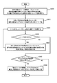
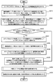
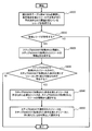
- 4 is a flowchart for explaining a process of registering a storage apparatus or a host computer as a management target of management software in the first embodiment.
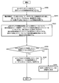
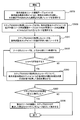
- 5 is a flowchart for explaining a process in which management software searches for a free resource from the resources of the storage apparatus according to the first embodiment.
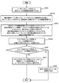
- 10 is a flowchart for explaining another process in which the management software searches for a free resource from among the resources of the storage apparatus according to the first embodiment.
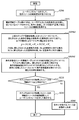
- 10 is a flowchart for explaining another process in which the management software searches for a free resource from among the resources of the storage apparatus according to the first embodiment.
- 10 is a flowchart for explaining another process in which the management software searches for a free resource from among the resources of the storage apparatus according to the first embodiment.
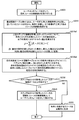
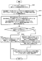
- FIG. 6 is a flowchart for explaining a process in which management software identifies a resource that hardly meets a condition specified by a user from among resources of the storage apparatus according to the first embodiment.
- FIG. 10 is a flowchart for explaining processing in which management software searches for a free resource from resources of a storage apparatus in the second embodiment. 10 is a flowchart for explaining processing in which management software updates an unnecessary resource determination threshold in the second embodiment. 10 is a flowchart for explaining processing in which management software calculates a condition non-applicable score in consideration of the execution frequency of management operations in the second embodiment.
- FIG. 10 is a flowchart for explaining a process in which management software identifies a resource that hardly meets a condition specified by a user from among resources of a storage apparatus in the second embodiment.
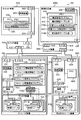
- It is a figure which shows schematic structure of the computer system in 3rd Embodiment.
- It is a figure which shows the structural example of the management authority information table group in 3rd Embodiment.
- It is a figure which shows the structural example of the user information table in 3rd Embodiment.
- FIG. 10 is a flowchart for explaining processing for specifying a resource in which management software does not substantially meet a condition specified by a user from among resources of a storage apparatus in the third embodiment.
- 14 is a flowchart for explaining a process in which management software presents information about resources that hardly match a condition designated by a user to a user in the third embodiment. It is a figure which shows schematic structure of the computer system in 4th Embodiment. 14 is a flowchart for explaining a process in which management software searches for a free resource from resources of a storage apparatus in the fourth embodiment.
- FIG. 1 It is a figure which shows the structural example of the user interface (search result of a logical volume) by this invention in 4th Embodiment. It is a figure which shows schematic structure of the computer system in 5th Embodiment. It is a figure which shows the structural example of the frequent appearance condition table group in 5th Embodiment. It is a figure which shows the structural example of the volume frequent appearance condition table in 5th Embodiment. It is a figure which shows the structural example of the pool frequent appearance condition table in 5th Embodiment. It is a figure which shows the structural example of the physical resource frequent appearance condition table in 5th Embodiment. FIG.
- the management software is a flowchart for explaining processing in which management software identifies a resource that hardly meets a condition specified by a user from among resources of a storage apparatus in the fifth embodiment.
- the management software is a flowchart for explaining processing for determining a measure for improving resource utilization efficiency for a resource that hardly meets a condition specified by a user.
- the embodiment of the present invention may be implemented by software running on a general-purpose computer, or may be implemented by dedicated hardware or a combination of software and hardware.
- each information of the present invention will be described in a “table” format.
- the information does not necessarily have to be expressed in a data structure by a table, such as a data structure such as a list, a DB, a queue, or the like. It may be expressed as Therefore, “table”, “list”, “DB”, “queue”, etc. may be simply referred to as “information” to indicate that they do not depend on the data structure.
- the expressions “identification information”, “identifier”, “name”, and “ID” can be used, and these can be replaced with each other.
- program as a subject (operation subject).
- a program is executed by a processor and a process determined by a memory and a communication port (communication control device). Since it is performed while being used, the description may be made with the processor as the subject.
- processing disclosed with the program as the subject may be processing performed by a computer such as a management computer or an information processing apparatus.
- Part or all of the program may be realized by dedicated hardware, or may be modularized.
- Various programs may be installed in a computer or information processing apparatus by a program distribution server or a non-temporary storage medium.
- the processor operates as a functional unit that realizes a predetermined function by operating according to a program.
- the processor functions as a control unit by operating according to the control program, and functions as a management unit by operating according to the management program.
- An apparatus and a system including a processor are an apparatus and a system including these functional units.
- a score indicating the degree of the storage resources that do not match the conditions for example, , The number of times the search did not match the condition
- the reason the condition that did not match during the search
- the management system detects a resource that is hardly used within a predetermined period before the current date and time, and information on the storage resource (for example, configuration information, the aforementioned score, The above reason) is presented to the administrator who is the user.
- each time the management system searches for a storage resource it records the condition specified by the administrator together with the specified number of times and the rate at which no storage resource satisfying the condition was found. Based on these pieces of information, the management system determines a measure for improving the use efficiency of the storage resource and presents it to the user for the storage resource that is determined to hardly meet the condition specified by the user.
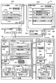
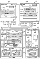
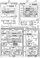
- FIG. 1 is a diagram showing a schematic configuration of a computer system according to the first embodiment of the present invention.
- the computer system 100 includes a storage device 1000, a host computer 2000, a switch device 3000, a management computer 4000, a switch device 5000, and a second storage device 6000.
- FIG. 1 there are two storage apparatuses 1000 and one host computer 2000, one switch apparatus 3000, one management computer 4000, and one switch apparatus 5000, but this is not restrictive. There should be more than one unit. In FIG. 1, there are two second storage devices 6000. However, this is not limited to this, and there may be three or more, or none.
- the storage apparatus 1000, the second storage apparatus 6000, and the host computer 2000 are connected to the network via the switch apparatus 3000.
- the storage apparatus 1000, the second storage apparatus 6000, the host computer 2000, and the management computer 4000 are connected to the network via the switch apparatus 5000.
- the switch device 3000 and the switch device 5000 may be the same device.
- the switch device 5000 may be divided into a storage device 1000, a second storage device 6000, a device that connects the management computer 4000, and a device that connects the host computer 2000 and the management computer 4000.
- the switch device 5000 includes an I / F (Interface) (A) 5100 for connection to the storage device 1000 and the second storage device 6000, and an I / F (B) 5200 for connection to the management computer 4000. And an I / F (C) 5300 for connection with the host computer 2000.
- I / F Interface
- A I / F
- B I / F
- C I / F
- Network protocols used between the storage apparatus 1000, the second storage apparatus 6000, the management computer 4000, the host computer 2000, and the switch apparatus 5000 that connects these include TCP / IP, but are particularly limited. I do not. In the figure, there is one I / F (A) 5100, one I / F (B) 5200, and one I / F (C) 5300. It only has to exist.
- the management computer 4000 and the storage apparatus 1000 are shown as apparatuses having separate enclosures. However, the present invention is not limited to this, and the management computer 4000 may exist in the same casing as the storage apparatus 1000. . Similarly, the management computer 4000 may exist in the same casing as the second storage device 6000.
- the storage device 1000 includes a disk device 1100 and a disk controller 1200.
- the disk device 1100 has a physical resource 1121 and a pool 1120.
- the physical resource 1121 represents a storage area resource provided by a physical device such as an HDD (Hard Disk Drive) or an SSD (Solid State Drive).
- the type of physical device that provides the physical resource 1121 is not particularly limited.
- the pool 1120 is a group of physical resources 1121.
- the pool 1120 is configured by making the physical resource 1121 redundant by using a technique called RAID (Redundant Array of Independent Disks), but this is not restrictive, and one or more physical resources 1121 are grouped. What is necessary is just to be. In the figure, there are four pools 1120 and five physical resources 1121, but this is not restrictive, and one or more may be present.
- RAID Redundant Array of Independent Disks
- the pool 1120 connected to the logical volume 1110 (1) is configured by RAID
- the pool 1120 connected to the logical volume 1110 (2) provides a virtual volume based on Thin Provisioning technology or Automated Tiering technology. It is configured.
- this is not restrictive, and both may be configured with RAID, or both may be configured to provide virtual volumes.
- the pool 1120 that provides the virtual volume may be configured from the logical volume 1110 instead of the physical resource 1121 depending on the hardware specifications of the storage apparatus 1000.
- the physical resource 1121 constitutes a pool 1120 configured with RAID
- the logical volume 1110 (1) cut out from the pool 1120 configured with RAID configures the pool 1120 that provides the virtual volume
- the virtual volume The logical volume 1110 (2) is cut out from the pool 1120 that provides.
- the configuration of the pool 1120 that provides the virtual volume is not particularly limited.
- the disk controller 1200 includes a memory 1210, a control device (also referred to as a processor) 1220, an I / F (A) 1230 for connection to the switch device 3000, and an I / F (for connection to the switch device 5000 ( B) 1240 and a disk I / F 1250 for connection to the disk device 1100. These components are connected through a bus.
- the disk controller 1200 further has a logical volume 1110.
- the logical volume 1110 is composed of one or more physical resources and represents a logical storage area provided to the host computer 2000 by the disk controller 1200.
- the logical volume 1110 (1) is composed of one or a plurality of physical resources 1121 that are allocated in advance, and the capacity of the logical volume 1110 (1) and the total capacity of the physical resources 1121 constituting the logical volume 1110 (1). Is equal to However, when physical resources are made redundant by RAID, the capacity of the logical volume 1110 (1) may be smaller than the total capacity of the physical resources 1121 constituting the logical volume 1110 (1).
- the logical volume 1110 (2) is a virtual logical volume provided to the host computer 2000, and a physical resource 1121 is allocated in response to a write request from the host computer 2000. Specifically, when the disk controller 1200 receives a data write request to the logical volume 1110 (2), if the physical resource is not allocated to the target area of the write request, the disk controller 1200 stores the physical resource 1121. An area is allocated to the logical volume 1100 (2), and data is written to the storage area of the allocated physical resource.
- the storage capacity of the logical volume 1110 (2) provided to the host computer 2000 can be made larger than the total capacity of the physical resources 1121 actually allocated.
- a technique for realizing this is called a Thin Provisioning technique.
- the logical volume 1110 (2) is configured from a plurality of physical resources 1121
- the type of physical device (HDD, SSD, etc.) that is the source of the physical resource 1121 may be different.
- the physical resource that is the storage destination of data written to the logical volume 1110 (2) is dynamically changed according to the access frequency from the host computer 2000 by the Automated Tiering function of the storage apparatus 1000. Can do.
- data with high access frequency from the host computer 2000 is stored in a physical resource provided from a high-speed but expensive physical medium (physical storage drive) such as SSD, and the access frequency from the host computer 2000 is high.
- a physical resource provided from a high-speed but expensive physical medium such as SSD
- the access frequency from the host computer 2000 is high.
- Control of storing low data in a physical resource provided from a low-speed but inexpensive physical medium such as SATA is possible.
- the above-described two types of logical volumes 1110 exist one by one.
- the present invention is not limited to this, and only one or two types may be mixed, and one or more logical volumes may be present. It is sufficient that the volume 1110 exists.
- the memory 1210 stores programs and data used by the control device 1220.
- the memory 1210 includes a storage information providing program 1211, a storage configuration information table group 1212, a storage virtualization program 1213, and a storage failure notification program 1214.
- the storage information provision program 1211 is a program that collects configuration information of the storage apparatus 1000 and transmits the information to another program (configuration management program 4110).
- the storage configuration information table group 1212 is a set of tables for storing configuration information of the storage apparatus 1000.
- the storage virtualization program 1213 is a program for realizing a virtualization function. Specifically, the storage virtualization program 1213 has a function of mapping the logical volume 6110 in the second storage device 6000 connected via the switch device 3000 to the logical volume 1110 in the first storage device 1000. Have. As a result, the logical volume 6110 of the second storage device 6000 can be provided to the host computer 2000 as the logical volume of the first storage device 1000.
- the virtualization function disclosed in Patent Documents 2 and 3 can be used.
- the logical volume 6110 of the second storage device 6000 may be mapped as the logical volume 1110, or the logical volume 6110 may be mapped to the pool 1120.
- the logical volume 1110 may be cut out from the pool.
- the logical volume 6110 may be mapped as a physical resource 1121 and a logical volume 1110 may be cut out after configuring a pool from the corresponding physical resource.
- the virtualization function may be realized by the switch device 3000.
- the first storage device 1000 and the second storage device 6000 may have a one-to-one relationship, or may have a one-to-many, many-to-one, or many-to-many relationship.
- the storage failure notification program 1214 is a program for notifying other programs (configuration management program 4110) of information on failures that have occurred in the storage apparatus 1000.
- the type of failure includes, for example, failure of a physical device that provides the physical resource 1121, but is not particularly limited.
- the control device 1220 controls the execution of programs in the memory 1210 and the input / output of data, and the input / output of data and control commands through each I / F of the disk controller 1200.
- the storage apparatus 1000 has a function of configuring a pool 1120 from physical resources 1121, a function of generating a logical volume 1110 from the pool 1120, a function of allocating a logical volume to the host computer 2000 through the I / F (A) 1230, a management computer
- the storage device 1000 has general functions as a storage device, such as a function of accepting a change request of the configuration and setting of the storage device 1000 from 4000.
- the storage apparatus 1000 may include an input apparatus for a user of the storage apparatus 1000 to input data and an output apparatus for presenting information to the user of the storage apparatus 1000. Since it is not directly related to, it is not shown. Since the configuration of the second storage device 6000 is the same as that of the storage device 1000, description thereof is omitted.
- the host computer 2000 is used to connect the memory 2100, a control device (also referred to as a processor) 2200, an I / F (A) 2300 for connection to the switch device 3000, and the switch device 5000. I / F (B) 2400. These components are connected through a bus.
- the memory 2100 stores programs and data used by the control device 2200.
- the memory 2100 includes an application program 2110 and a host information providing program 2120.
- Application program 2110 may be any program.
- the host information providing program 2120 is a program that collects configuration information of the host computer 2000 and transmits the information to another program (configuration management program 4110).
- the host information providing program may be a program different from the OS (Operating System) or may be realized as a function of the OS itself.
- the control device 2200 controls execution of programs in the memory 2100 and input / output of data, and input / output of data and control commands through the I / F (A) 2300 and I / F (B) 2400.
- the host computer 2000 also has an input device (keyboard, pointing device such as a mouse, voice input device, etc.) for the user of the host computer 2000 to input data, and an output for presenting information to the user of the host computer 2000.
- an input device keyboard, pointing device such as a mouse, voice input device, etc.
- an output for presenting information to the user of the host computer 2000.
- a device display device, printer, audio output device, etc.
- a secondary storage device for storing data may be included, but they are not shown because they are not directly related to the present invention.
- the switch device 3000 has an I / F (A) 3100 for connection to the storage device 1000 and the second storage device 6000, and an I / F (B) 3200 for connection to the host computer 2000. is doing.
- Network protocols used between the storage device 1000, the second storage device 6000, the host computer 2000, and the switch device 3000 connecting them include FC (Fibre Channel) and iSCSI, but are not particularly limited.
- FC Fibre Channel
- iSCSI iSCSI
- the management computer 4000 includes a memory 4100, a control device (also referred to as a processor) 4200, and an I / F 4300 for connection to the switch device 5000.
- the memory 4100 stores programs and data used by the control device 4200.
- the memory 4100 includes a configuration management program 4110, a configuration information table group 4120, an unnecessary resource specifying program 4130, and an unnecessary resource specifying table group 4140.
- the configuration management program 4110 is a program for managing the configurations of the storage apparatus 1000, the second storage apparatus 6000, and the host computer 2000.
- the configuration management program 4110 has a function of acquiring the configuration information of the storage apparatus 1000 by communicating with, for example, the storage information providing program 1211 that the storage apparatus 1000 has.
- the configuration management program 4110 communicates with the host information provision program 2120 of the host computer 2000 to acquire the configuration information of the host computer 2000, the storage failure notification program 1213, and the host failure notification program 2130. To the storage subsystem 1000 and the host computer 2000.
- the configuration management program 4110 may acquire other information such as performance information in addition to the configuration information of the storage apparatus 1000 and the host computer 2000.
- the configuration management program 4110 has a general function as a management computer.
- they include a function that configures the pool 1120 from the physical resource 1121, a function that generates a logical volume 1110 from the pool 1120, a function that allocates the logical volume 1110 to the host computer 2000 through the I / F (A) 1230, and a specification.
- a scheduler function for performing a specific process at a certain time a function for searching for a resource such as a logical volume of the storage apparatus, and the like.
- the configuration management program 4110 provides a user interface for displaying configuration information of the storage apparatus 1000 and the host computer 2000 and performing management operations for the storage apparatus 1000 and the host computer 2000.
- the configuration information table group 4120 is a set of tables for storing configuration information of the storage apparatus 1000 and the host computer 2000.
- the unnecessary resource specifying program 4130 is a program for specifying a resource that is difficult to use from among resources of the storage apparatus 1000 and the second storage apparatus 6000.
- the unnecessary resource specifying table group 4140 stores information used when the unnecessary resource specifying program 4130 specifies a resource that is difficult to use from the resources of the storage apparatus 1000 and the second storage apparatus 6000. It is a set of tables to perform.
- the management computer 4000 has an input device for the user of the management computer 4000 to input data, an output device for presenting information to the user of the management computer 4000, and a secondary storage device for storing data. You may do it. Further, the various tables possessed by the management computer 4000 may be held not only on the memory but also on the secondary storage device.
- a serial interface or an Ethernet interface is used as an input / output device, and a display computer having a display, keyboard, or pointer device is connected to the interface and displayed.
- the display information is sent to the display computer, or the input information is received from the display computer, so that the display computer can display or accept the input to replace the input and display on the input / output device. Also good.
- management computer 4000 may be realized by having the program in the memory 4100 of the management computer 4000 in the memory 1210 of the storage device 1000 and executing the program by the control device 1220. Furthermore, the management computer 4000 may also have a program for managing the switch device 3000 and the switch device 5000.
- a set of one or more computers that manage the computer system 100 and display the display information of the present invention may be referred to as a management system.
- the management computer 4000 displays display information
- the management computer 4000 is a management system
- the combination of the management computer 4000 and the display computer is also a management system.
- a plurality of computers may realize processing equivalent to that of the management computer.
- the plurality of computers if the display computer performs the display, display (Including computers) is the management system.
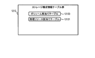
- FIG. 2 is a diagram illustrating a configuration example of the storage configuration information table group 1212.
- the storage configuration information table group 1212 has a volume allocation table 12120 and a physical resource allocation table 12121.
- the volume allocation table 12120 is a table for storing information on the logical volume 1110 allocated to the host computer 2000.
- the physical resource allocation table 12121 stores physical resource allocation information for each segment of the logical volume 1110.
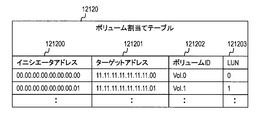
- FIG. 3 is a diagram showing a specific configuration example of the volume allocation table 12120.
- the volume allocation table 12120 includes, as configuration items, an initiator address 121200 for identifying the I / F (A) 2300 possessed by the host computer and a target address for identifying the I / F (A) 1230 possessed by the storage apparatus 1000. 121201, a volume ID 121202 for identifying the logical volume 1110, and a LUN (Logical Unit Number) 121203 for specifying a set of the I / F (A) 1230 and the logical volume 1110.
- an initiator address 121200 for identifying the I / F (A) 2300 possessed by the host computer
- a target address for identifying the I / F (A) 1230 possessed by the storage apparatus 1000.
- 121201 a volume ID 121202 for identifying the logical volume 1110
- LUN Logical Unit Number
- the WWN World Wide Name
- the present invention is not limited to this.
- the LUN 121202 is used as an identifier for specifying a set of the I / F (A) 1230 and the logical volume 1110.
- the present invention is not limited to this, and the I / F (A) 1230 and the logical volume 1110 Any information may be used as long as the set can be uniquely identified.
- FIG. 4 is a diagram showing a configuration example of the physical resource allocation table 12121 in the present embodiment.
- the physical resource allocation table 12121 includes, as configuration items, a volume ID 121210 for identifying the logical volume 1110, a segment ID 121211 for identifying a segment in the logical volume, and an area for each segment of the logical volume 1110. And a volume LBA (Logical Block Address) area 121212.
- a volume ID 121210 for identifying the logical volume 1110
- segment ID 121211 for identifying a segment in the logical volume
- a volume LBA Logical Block Address
- the physical resource allocation table 12121 further includes, as configuration items, a storage ID 121213 for identifying a storage device that is a physical resource providing source, and a physical resource for identifying a physical resource allocated to each segment of the logical volume 1110. ID 121214, and an LBA area 121215 for identifying the storage area of the physical resource 1121 allocated to each segment of the logical volume 1110.
- the storage area of the logical volume 6110 of the second storage device 6000 is allocated to the segment of the logical volume 1110 (for example, in FIG. 4, the volume ID 121210 is “Vol.1” and the segment ID 121111 is “Seg. 1 ”)
- the storage ID 121213 is “Vol.1” and the segment ID 121111 is “Seg. 1 ”
- information for identifying the second storage device 6000 is stored in the storage ID 121213
- information for identifying the logical volume 6110 of the second storage device 6000 is stored in the physical resource ID 121214, respectively.
- the storage area of the physical resource 1121 possessed by the storage apparatus 1000 itself is allocated to the segment of the logical volume 1110
- information identifying the first storage apparatus 1000 is stored in the physical resource ID 121214 in the storage ID 121213.
- the method for indicating the relationship between virtualization and virtualization by the storage virtualization program is not limited to the expression in FIG. 4, and other methods may be used.
- the volume ID 121210, the segment ID 121121, the storage device ID 121213, and the physical resource ID 121214 are the logical volume 1110, the segment in the logical volume 1110, the storage device 1000 or the second storage device 6000, and the physical resource, respectively. 1121 or information that can uniquely identify the logical volume 6110 of the second storage device 6000. Therefore, they are not limited to the notation shown in FIG.
- volume LBA area 121212 and the LBA area 121215 are information that can uniquely identify the segment area in the logical volume 1110 and the storage area in the physical resource 1121, respectively. Not limited to this, other information may be used.
- the row in which “null” is stored in the physical resource ID 121213 and LBA area 121214 columns (the row in which the volume ID 121210 is “Vol.1” and the segment ID 121111 is “Seg.2”) is the host computer. There is no write request from the host computer 2000 for some segments of the virtual logical volume 1110 (2) provided to 2000, so the storage area of the physical resource 1121 is still allocated to the segment. Indicates that it is not.
- FIG. 5 is a diagram illustrating a configuration example of the configuration information table group 4120.
- the configuration information table group 4120 includes a storage information table 4121, a volume information table 4122, a pool information table 4123, a physical resource information table 4124, a pool / resource related information table 4125, and a host information table. 4126 and a volume allocation information table 4127.
- the storage information table 4121 is a table for storing information of the storage apparatus 1000 and the second storage apparatus 6000.
- the volume information table 4122 is a table for storing information on the logical volume 1110 of the storage apparatus 1000 and the logical volume 6110 of the second storage apparatus 6000.
- the pool information table 4123 is a table that stores information on the pool 1120 that the storage apparatus 1000 has and the pool 6120 that the second storage apparatus 6000 has.
- the physical resource information table 4124 is a table that stores information on the physical resources 1121 that the storage apparatus 1000 has and the physical resources 6121 that the second storage apparatus 6000 has.
- the pool / resource related information table 4125 is a table for storing information on the relationship between the pool 1120 and the physical resource 1121 that the storage apparatus 1000 has, and the relationship between the pool 6120 and the physical resource 6121 that the second storage apparatus 6000 has. .
- the host information table 4126 is a table for storing information of the host computer 2000.
- the volume allocation information table 4127 is a table showing the relationship between the host computer 2000 and the logical volume 1110 or logical volume 6110 allocated to the host computer 2000.
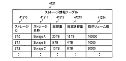
- FIG. 6 is a diagram showing a specific configuration example of the storage information table 4121.
- the storage information table 4121 includes, as configuration items, a storage ID 41210 for identifying the storage apparatus 1000 or the second storage apparatus 6000, a storage name 41111 indicating the name of the storage apparatus 1000 or the second storage apparatus 6000, and a storage apparatus And the total capacity 41212 of the pool 1120 that the 1000 has or the pool 6120 that the second storage device 6000 has.
- the storage information table 4121 further includes, as configuration items, the total free capacity 41213 of the pool 1120 of the storage apparatus 1000 or the pool 6120 of the second storage apparatus 6000 and the total number of logical volumes 1110 of the storage apparatus 1000 or 2 and a total volume number 41214 which is the total number of logical volumes 6110 of the second storage apparatus 6000.
- the storage information table 4121 is not limited to the information shown in FIG. 6, but may store other information of the storage device 1000 or the second storage device 6000.
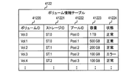
- FIG. 7 is a diagram illustrating a specific configuration example of the volume information table 4122.
- the volume information table 4122 has, as configuration items, a volume ID 41220 for identifying the logical volume 1110 or the logical volume 6110, and a storage ID 41221 for identifying the storage apparatus 1000 or the second storage apparatus 6000.
- the volume information table 4122 further includes, as configuration items, a pool ID 41222 for identifying the pool 1120 from which the logical volume 1110 is cut out or the pool 6120 from which the logical volume 6110 is cut out, and the logical volume 1110 or logical volume 6110.
- the value of “normal” or “error” is stored in the status 41224.
- the value is not limited to this, and any information indicating the operating status of the logical volume 1110 or the logical volume 6110 may be used.
- the volume information table 4122 is not limited to the information shown in FIG. 7, but may store other information of the logical volume 1110 or the logical volume 6110.
- FIG. 8 is a diagram illustrating a specific configuration example of the pool information table 4123.
- the pool information table 4123 includes, as configuration items, a pool ID 41230 for identifying the pool 1120 or the pool 6120, and a storage ID 41231 for identifying the storage device 1000 or the second storage device 6000.
- the pool information table 4123 further includes, as configuration items, a total capacity 41232 of the pool 1120 or the pool 6120, a free capacity 41233 of the pool 1120 or the pool 6120, a type 41234 indicating the type of the pool 1120 or the pool 6120, a pool 1120 or It has a RAID level 41235 set in the pool 6120 and a state 41236 indicating the operating state of the pool 1120 or the pool 6120.
- the RAID level 41235 is information indicating the type of RAID technology applied to the pool 1120 or the pool 6120, that is, information indicating the degree of redundancy of the pool 1120 or the pool 6120.
- the pool ID 41230 is Pool. From the pool of 0 (total capacity 41232 is 10 TB), it can be seen that a capacity of 1 TB is cut out to configure a logical volume.
- any value of “Basic”, “Thin Provisioning”, and “Automated Tiering” is stored in the type 41234, but not limited to this, any information indicating the type of the pool may be used.
- the pool 1120 whose type 41234 is “Basic” indicates a pool in which the capacity of one or a plurality of physical resources 1121 can be allocated in advance to the logical volume 1110 (1). .
- a pool 1120 whose type 41234 is “Thin Provisioning” indicates a pool to which a physical resource 1121 can be allocated to the logical volume 1110 (2) in response to a write request from the host computer 2000. .
- the pool 1120 whose type 41234 is “Automated Tiering” is composed of physical resources provided from a plurality of types of physical devices, and indicates a pool capable of the following.
- the physical resource 1121 can be allocated to the logical volume 1110 (2) in response to a write request from the host computer 2000.
- the type of the physical resource 1121 allocated to the logical volume 1110 (2) can be changed according to the frequency of I / O access to the logical volume 1110 (2) from the host computer 2000. Data written in the storage area of the already allocated physical resource 1121 can be migrated to the storage area of another physical resource 1121.
- the status 41236 stores either “normal” or “error”, but is not limited to this, and any information indicating the operating status of the pool 1120 may be used.
- the pool information table 4123 is not limited to the information illustrated in FIG. 8 and may store other information of the pool 1120 or the pool 6120.
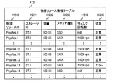
- FIG. 9 is a diagram illustrating a specific configuration example of the physical resource information table 4124.
- the physical resource information table 4124 includes a physical resource ID 41240 for identifying the physical resource 1121 or the physical resource 6121, a storage ID 41241 for identifying the storage device 1000 or the storage device 6000, and the capacity 41242 of the physical resource 1121 or the physical resource 6121. And as a configuration item.
- the physical resource information table 4124 further includes a media type 41243 indicating the type of storage area providing medium (storage drive) in the physical resource 1121 or physical resource 6121, and a storage area providing medium in the physical resource 1121 or physical resource 6121. And the state 41245 indicating the operating state of the physical resource 1121 or the physical resource 6121 as configuration items.
- any value of “SATA” and “SSD” is stored in the media type 41243, but the present invention is not limited to this, and any information indicating the type of media may be used.
- the disk rotation number 41244 stores “null”. This indicates that there is no disk in the SSD, so the disk cannot rotate.
- the method of indicating that there is no disk rotation is not limited to this, and other expression methods may be used.
- any value of “normal” and “error” is stored in the state 41245, but not limited to this, any information indicating the operating state of the physical resource 1121 or the physical resource 6121 may be used.
- the physical resource information table 4134 is not limited to the information illustrated in FIG. 9 and may store other information of the physical resource 1121 or the physical resource 6121.
- FIG. 10 is a diagram illustrating a specific configuration example of the pool / resource related information table 4125.
- the pool / resource related information table 4125 includes, as configuration items, a storage ID 41250 for identifying the storage apparatus 1000, a pool ID 41251 for identifying the pool 1120, and a physical resource 1121 that is a storage area providing source of the pool 1121.
- the pool / resource related information table 4125 further identifies the second storage apparatus 6000 as a configuration item when the storage area providing source of the pool 1120 is the logical volume 6110 of the second storage apparatus 6000. And external volume ID 41254 for identifying the logical volume 6110 of the second storage device 6000 as configuration items.
- pool / resource related information table 4125 is not limited to the information shown in FIG. 10, but may store other information indicating the relationship between the pool 1120 and the physical resource 1121 or the logical volume 6110.
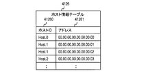
- FIG. 11 is a diagram illustrating a specific configuration example of the host information table 4126.
- the host information table 4126 includes, as configuration items, a host ID 41260 for identifying the host computer 2000 and an address 41261 assigned to the I / F (A) 2300 of the host computer 2000.
- the address 41261 stores the WWN assigned to the I / F (A) 2300 of the host computer 2000.
- the present invention is not limited to this, and the network assigned to the I / F (A) 2300 is stored. Any information indicating an address may be used.
- the host information table 4126 is not limited to the information shown in FIG. 11, but may store other information of the host computer 2000.
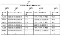
- FIG. 12 is a diagram showing a specific configuration example of the volume allocation information table 4127.
- the volume allocation information table 4127 includes, as configuration items, a host ID 41270 for identifying the host computer 2000 and an initiator address 41271 indicating an address allocated to the I / F (A) 2300 of the host computer 2000.
- the volume allocation information table 4127 further includes, as configuration items, a storage ID 41272 for identifying the storage apparatus 1000 or the second storage apparatus 6000, and an I / F (A) included in the storage apparatus 1000 or the second storage apparatus 6000. And a target address 41273 indicating an address assigned to 1230, and a volume ID 41274 for identifying the logical volume 1110 or the logical volume 6110.
- the volume assignment information table 4127 is not limited to the information shown in FIG. 12, and may store other information related to the relationship between the host computer 2000 and the logical volume 1110 or logical volume 6110 assigned to the host computer 2000. Good.
- FIG. 13 is a diagram showing a specific example of the unnecessary resource specifying table group 4140.
- the unnecessary resource specifying table group 4140 includes a condition non-applicable resource information table 4141.
- the condition non-applicable resource information table 4141 includes storage resources such as logical volumes, pools, and physical resources that the storage apparatus 1000 and the second storage apparatus 6000 have (hereinafter collectively referred to as resources or storage resources). It is a table for storing information indicating how difficult it is to meet a condition required by an administrator (hereinafter simply referred to as a condition) and information indicating a reason when a storage resource does not match the condition.
- FIG. 14 is a diagram illustrating a specific configuration example of the condition non-applicable resource information table 4141.
- the condition non-applicable resource information table 4141 includes, as configuration items, a resource ID 41410 for identifying the resource, a condition non-applicable score 41411 indicating the degree of difficulty of the resource matching the condition, and the date and time when the resource last met the condition. And a condition non-applicable reason count 41413 indicating a reason when the resource does not match the condition.
- the condition non-applicable reason count 41413 includes an item indicating that the condition is not satisfied because the capacity is small and the pool type is “Basic”. There are an item indicating that there is an item, an item indicating that the type of media is “SATA”, and an item indicating that the reason is that the disk rotation speed is slow. It may include other items indicating the reason for not meeting the conditions.
- condition non-applicable score 41411 The specific calculation method of information stored in the condition non-applicable score 41411 will be described later. For example, when the configuration management program 4110 searches for a resource in the condition non-applicable score 41411, the resource does not match the condition. The total number of searches is stored.
- condition non-applicable reason count 41413 corresponds to a condition that is not satisfied when the resource does not meet the condition. For each reason, the total number of unsatisfied times is stored.
- the initial values of the condition non-applicable score 41411, the condition applicable final date 41414, and the condition non-applicable reason count 41413 are “0”, “null”, and “0”, respectively.
- condition non-applicable score 41411 of the logical volume A remains “0”, and “1” is stored in the condition non-applicable score 41411 of the logical volume B.
- the date and time when the search was executed (for example, “2011/11/1 20:00”) is stored in the condition applicable final date 4112. Since the logical volume B did not meet the condition, the condition applicable final date 4112 of the logical volume B remains “null”. Further, all items of the logical volume A condition non-applicable reason count 41413 remain “0”, whereas the item “logical capacity small” of the logical volume B condition non-applicable reason count 41413 has “1”. Stored.
- condition non-applicable score 41411, the condition applicable final date 41411, and the condition non-applicable are the same procedure.
- the reason count 41413 is updated.
- FIG. 15 is a flowchart for explaining processing when the configuration management program 4110 registers the storage apparatus 1000, the second storage apparatus 6000, and the host computer 2000 as management targets in this embodiment. Note that the processing for the second storage device 6000 is the same as the processing for the storage device 1000, and a description thereof will be omitted.
- step S1000 the administrator (user) instructs to register the storage apparatus 1000 and the host computer 2000 as management targets of the configuration management program 4110 via the user interface of the configuration management program 4110. 4110 receives the instruction.
- the administrator when an administrator (user) designates a storage device 1000 or host computer 2000 that has already been registered, the administrator stores the storage device 1000 or the storage device 1000 stored in the configuration information table group 4120. It is assumed that the host computer 2000 is instructed to reacquire and update the configuration information.
- step S1010 the configuration management program 4110 communicates with the storage information providing program 1211 on the storage apparatus 1000 and the host information providing program 2120 on the host computer 2000 to obtain the configuration information of the storage apparatus 1000 and the host computer 2000. Acquired and stored in the configuration information table group 4120.
- the configuration management program 4110 notifies the administrator that the storage apparatus 1000 and the host computer 2000 have been registered as management targets.
- the notification method includes a notification method via a user interface such as GUI (Graphical User Interface) or CLI (Command Line Interface), or a method of outputting a message to a log, but is not particularly limited.
- the processing for registering the storage apparatus 1000 and the host computer 2000 as the management target of the configuration management program 4110 is completed.
- This process does not necessarily have to be executed when the user registers the storage apparatus 1000 or the host computer 2000 as a management target of the configuration management program 4110.
- the configuration management program 4110 detects the presence of the storage device 1000 or the host computer 2000 connected via the switch device 5000, and executes the registration process as a trigger. May be.
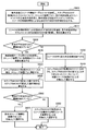
- FIG. 16 is a flowchart for explaining processing when the configuration management program 4110 searches for a specific free resource from the resources of the storage apparatus 1000 and the second storage apparatus 6000 in this embodiment. Note that the processing for the second storage device 6000 is the same as the processing for the storage device 1000, and a description thereof will be omitted.
- step S1000 the administrator (user) instructs execution of a search together with a condition (search condition) for searching for a specific free resource via the user interface of the configuration management program 4110.
- the configuration management program 4110 Accept the instruction.
- step S2010 the configuration management program 4110 compares the information stored in the configuration information table group 4120 with the conditions (search conditions) entered by the user, and matches the search conditions from the available resources.
- the configuration management program 4110 determines that the logical volume is free when the logical volume is not allocated to the host computer.
- the configuration management program 4110 determines that the pool is free when the free capacity of the pool is 0 or more.
- the configuration management program 4110 determines that the physical resource is free when the physical resource does not constitute a pool.
- a method for determining whether or not the search condition is met for example, when the value indicated by the search condition and the value acquired from the configuration information table group 4120 completely match, it is determined that the search condition is met. And a method of determining that the search condition is met when the value acquired from the configuration information table group 4120 is included in the value indicated by the search condition.
- the former is a method in which, for example, when a logical volume is searched under the search condition “capacity is 500 GB”, it is determined that only the logical volume whose capacity is exactly 500 GB matches the search condition.
- the latter is a method of determining that a logical volume with a capacity of 500 GB or a logical volume with a capacity of 1 TB matches the condition when a logical volume is searched under a search condition of “capacity is 500 GB or more”, for example. is there.
- step S2020 the configuration management program 4110 does not acquire information in step S2010 (the free resource not corresponding to the condition in step S2010, that is, the free resource or state that does not match the search condition is “normal”.
- the condition non-applicable score 41411 of the condition non-applicable resource information table 4141 is incremented, and the condition non-applicable reason count 41413 corresponding to the condition that the resource is not satisfied is incremented.
- the configuration management program 4110 executes the condition corresponding final in the condition non-applicable resource information table 4141.
- the current date is stored in the date 41414.
- step S2030 the configuration management program 4110 determines whether there is information on one or more resources acquired in step S2010 (that is, one or more resources determined to meet the conditions in step S2010). Or not).
- step S2030 If there is information on one or more corresponding resources (YES in step S2030), the configuration management program 4110 moves to step S2040. If there is no information about one or more corresponding resources (NO in step S2030), the configuration management program 4110 proceeds to step S2050.
- step S2040 the configuration management program 4110 displays the resource information acquired in step S2010 as a resource search result via the user interface.
- step S2050 the configuration management program 4110 automatically generates resources that match the conditions specified by the user.
- the processing in step S2050 may not be necessary depending on the use case of the search function. For example, when the search function is used in a series of processes that configure a management operation for allocating the logical volume 1110 to the host computer 2000, if there is no logical volume that meets the conditions, the configuration management program 4110 executes step S2050. A logical volume that meets the conditions may be automatically generated by processing.
- the configuration management program 4110 when the user selects a resource obtained as a search result and executes a management operation after the search function is executed, the configuration management program 4110 does not have to execute the process of step S2050. As described above, the configuration management program 4110 can determine whether or not to execute the process of step S2050 according to which process the process of FIG. 16 is executed from.
- FIG. 17 is a flowchart for explaining another example of processing when the configuration management program 4110 searches for a free resource from the resources of the storage apparatus 1000 and the second storage apparatus 6000 in this embodiment. It is. Since most of the processing in FIG. 17 is the same as the processing in FIG. 16, differences from the processing in FIG. 16 will be described.
- the configuration management program 4110 executes the process of step S2010a1 after the process of step S2000 is completed.
- step S2010a1 the configuration management program 4110 compares the information stored in the configuration information table group 4120 with the conditions (search conditions) input by the user, and resources that match the search conditions from among the available resources. Get information about.
- the configuration management program 4110 executes the process of step S2025a1 after step S2020 is completed.
- the configuration management program 4110 excludes information on resources whose status is not “normal” from the information on resources acquired in step S2010 (ie, resources that match the search condition).
- step S2010 it is determined in step S2010 that the resource does not meet the condition, and as a result, the condition non-applicable score 41411 of the condition non-applicable resource information table 4141 is incremented in step S2020.
- step S2010a1 it is determined in step S2010a1 that the resource matches the condition, and the condition non-applicable score 41411 is not incremented in step S2020.
- the resource is temporarily unavailable due to a failure or the like, but is based on the idea that the condition non-applicable score 41411 should not be incremented because it matches the search condition entered by the user. It is.
- the condition non-applicable score 41411 is information indicating the degree to which the resource is difficult to meet the condition.
- the purpose of the score is the frequency of use at the time of generation from the resources of the storage apparatus 1000 and the second storage apparatus 6000. However, it is to detect resources that are no longer used as the system continues to operate, and are almost no longer used (the process for doing so will be described later) .
- FIG. 18 is a flowchart for explaining another example of processing when the configuration management program 4110 searches for a free resource from the resources of the storage apparatus 1000 and the second storage apparatus 6000 in this embodiment. is there. Since most of the processes in FIG. 18 are the same as the processes in FIG. 16, differences from the processes in FIG. 16 will be described.
- the configuration management program 4110 executes the process of step S2015a2 after the process of step S2010 is completed.
- step S2015a2 the configuration management program 4110 sums up the number of unsatisfied conditions for the resources determined not to meet the conditions in step S2010, divided into the conditions that must be specified and optional conditions, and the following.
- the penalty value (p) is calculated by the following formula.
- NUMe is the number of essential conditions that are not satisfied
- Weight is a predetermined weight for the essential conditions
- NUMo is the number of optional conditions that are not satisfied
- Wo is the optional condition.
- a predetermined weight is the weight of the essential conditions.
- step S2020a2 the configuration management program 4110 adds the penalty value (p) calculated in step S2015a2 to the condition non-applicable score 41411 of the condition non-applicable resource information table 4141, and the condition not corresponding to the condition not satisfied The reason count 41413 is incremented. Further, the configuration management program 4110 stores the current date and time in the condition applicable last date and time 4112 for the resource that matches the condition.
- the process of FIG. 18 differs from the process of FIG. 16 in the method of increasing the value of the condition non-applicable score 41411.
- the number of satisfied conditions can be reflected in the condition non-applicable score 41411, and the condition that must be specified and the condition that is specified can be specified by a predetermined weight. You can make a difference.
- the value of the weight and how to determine it are not particularly limited. For example, the weight of the condition that must be specified can be determined as 2, and the condition that can be specified as 1 can be determined.
- the condition non-applicable score 41411 increases by 1 for both logical volumes.
- FIG. 19 is a flowchart for explaining another example of processing when the configuration management program 4110 searches for a free resource from the resources of the storage apparatus 1000 and the second storage apparatus 6000 in this embodiment. . Since many of the processes in FIG. 19 are the same as the processes in FIG. 18, differences from the processes in FIG. 18 will be described.
- step S2015a3 the configuration management program 4110 sums up the number of resources that satisfy the condition for each of the resources determined not to meet the condition in step S2010, and calculates a penalty value (p) by the following formula: To do.
- Bi is a constant that is 1 when the i-th condition is not satisfied, 0 when it is satisfied, NUMi is the number of resources that satisfy the i-th condition, and C is a predetermined constant (for example, 100). .
- the penalty value (p) calculation method between the process of FIG. 18 and the process of FIG. By performing the processing as shown in FIG. 19, the score that satisfies the condition (in this embodiment, the condition that the condition is satisfied is expressed using the number of resources that satisfy the condition). 41411 can be reflected.
- condition non-applicable score 41411 by the processing of FIG. 19 will be described using a specific example.
- a search for an empty logical volume is taken as an example.
- search conditions “capacity”, “type”, and “RAID level”. It is assumed that logical volume A and logical volume B do not meet the conditions as a result of searching the logical volume by specifying these conditions.
- the number of resources satisfying the “capacity” condition is 1000
- the number of resources satisfying the “type” condition is 500
- the number of resources satisfying the “RAID level” condition is 300. .
- the condition non-applicable score 41411 increases by 5 for the logical volume A, but increases by 18 for the logical volume B.
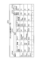
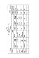
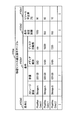
- FIG. 20 to 23 are diagrams showing a configuration example of a user interface of the configuration management program 4110 according to the embodiment of the present invention.
- FIG. 20 corresponds to a user interface for searching for free resources.
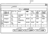
- FIG. 21 corresponds to a user interface showing search results for logical volumes.
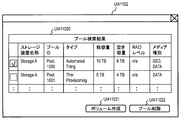
- FIG. 22 corresponds to a user interface showing search results for the pool.
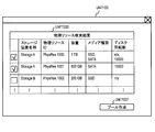
- FIG. 23 corresponds to a user interface showing search results for physical resources.
- a free resource search user interface UI 41100 includes, as components, a search target selection area UI 411000, a storage apparatus condition input area UI 411001, a capacity condition input area UI 411002, and a type condition. Input area UI411003.
- the free resource search user interface UI 41100 further includes, as constituent elements, a RAID level condition input area UI 411004, a media type condition input area UI 411005, a disk rotation speed condition input area UI 411006, and a search execution.
- a button UI411007 for instructing and a button UI411008 for instructing cancellation of execution of the search are provided.
- the constituent elements of the free resource search user interface UI 41100 are not limited to the expressions in FIG. 20, and may include other constituent elements.
- the search condition input area may include a search condition input area for other attributes that characterize logical volumes, pools, and physical resources in addition to the elements shown in FIG.
- Such other attributes include, for example, the condition whether or not the data in the logical volume is encrypted, and the storage of the logical volume when the host computer has not accessed the logical volume for a certain period of time.
- There are conditions such as the presence / absence of a function for setting the operating state of the physical medium, which is the area provider, to the power saving state (or stopped state).
- Search conditions may be different for logical volumes, pools, and physical resources. For example, in the search target selection area UI411000, when the search target is selected, the display of the condition input area of the user interface UI41100 is dynamically displayed. You may switch to.
- the search target selection area UI411000 is an area for selecting the type of search target. In FIG. 20, one of “volume”, “pool”, and “physical resource” can be selected. Yes.
- the storage device condition input area UI411001 is an area for inputting conditions for narrowing down storage devices. In FIG. 20, from among “ANY”, “Storage A”, “Storage B”, and “Storage C”. Either one can be selected.
- Storage A “Storage B”, and “Storage C” are all examples of names of storage devices under the management of the configuration management program 4110.
- “ANY” the resources of all storage apparatuses under the management of the configuration management program 4110 are searched.
- An integer greater than 0 can be entered in the area for entering a numerical value indicating the capacity, and any one of “MB”, “GB”, and “TB” can be selected in the area for selecting the capacity unit. It has become.
- any one of “ANY”, “Automated Tiering”, “Thin Provisioning”, and “Basic” can be selected.
- ANY Automated Tiering
- Thin Provisioning and “Basic”
- any one of “ANY”, “RAID5”, “RAID6”, and “RAID1 + 0” can be selected in FIG.
- “ANY” is selected, all RAID level pools are searched.
- any one of “ANY”, “SSD”, “SAS”, and “SATA” can be selected in FIG.
- “ANY” pools of all media types are searched.
- any one of “ANY”, “15000 rpm”, “10000 rpm”, and “7200 rpm” can be selected in FIG.
- “ANY” a pool of all the disk rotation speeds is a search target.
- a condition input area that can select “ANY” indicates that the condition can be specified arbitrarily. That is, in FIG. 20, only “capacity” is a condition that must be specified, and other conditions can be specified.
- a user interface UI 41101 indicating a search result for a logical volume includes a search result UI 4111010 for a logical volume, a button UI 411011 for instructing allocation of a logical volume to a host computer, and a button for instructing logical volume virtualization
- a UI 411012 and a button UI 411013 for instructing deletion of a logical volume are included as components.
- the logical volume search result UI 411010 includes an area for selecting one or more logical volumes and an area for displaying logical volume attributes (storage device name, volume ID, type, etc.).
- logical volume attributes storage device name, volume ID, type, etc.
- the attribute of the logical volume is not limited to the expression shown in FIG. 21, and other attributes may be displayed.
- a user interface UI 41101 indicating a search result for a logical volume includes a button UI 411011 for instructing allocation of a logical volume to a host computer, a button UI 411012 for instructing logical volume virtualization, and a button UI 411013 for instructing deletion of a logical volume.
- the button may be a button for instructing execution of another setting operation for the logical volume.
- FIG. 21 is displayed by the process of step S2040 as a result of executing any one of the processes of FIGS. 16, 17, 18, and 19 on the logical volume.
- a user interface UI 41102 indicating a search result for a pool includes a pool search result UI 4111020, a button UI 410221 for instructing to create a logical volume from the pool, and a button UI 411022 for instructing to delete the pool. And as constituent elements.
- the pool search result UI 411020 includes an area for selecting one or more pools and an area for displaying pool attributes (storage device name, ID, type, etc.).
- pool attributes storage device name, ID, type, etc.
- the attributes of the pool are not limited to the expressions shown in FIG. 22, and other attributes may be displayed.
- the user interface UI 41102 indicating the search result for the pool is not limited to the button UI 4101221 for instructing to create a logical volume from the pool and the button UI 411022 for instructing to delete the pool, but other setting operations for the pool There may be a button for instructing the execution.
- FIG. 22 is displayed by the process of step S2040 as a result of executing any one of the processes of FIGS. 16, 17, 18, and 19 on the pool.
- a user interface UI 41103 indicating a search result for a physical resource includes, as components, a search result UI 4111030 for a physical resource and a button UI 410131 for instructing to create a pool from the physical resource. .
- the physical resource search result UI 4111030 includes an area for selecting one or more physical resources, and an area for displaying physical resource attributes (storage device name, physical resource ID, etc.).
- the attributes of the physical resource are not limited to the expressions in FIG. 23, and other attributes may be displayed.
- the user interface UI 41103 indicating the search result for the physical resource is not limited to the button UI 410331 for instructing to generate a pool from the physical resource, but may have a button for instructing execution of another setting operation for the physical resource. Good.
- FIG. 23 is displayed by the process of step S2040 as a result of executing any one of the processes of FIGS. 16, 17, 18, and 19 on the physical resource.
- FIG. 24 shows an example in which the unnecessary resource identification program 4130 identifies a resource that hardly meets the condition specified by the user from among the resources of the storage apparatus 1000 or the second storage apparatus 6000 in this embodiment. It is a flowchart for demonstrating the example of a process. Note that the processing in FIG. 24 can be executed at regular intervals by, for example, the scheduler function of the configuration management program 4110, but may be executed at other times.
- the unnecessary resource identification program 4130 compares the condition applicable final date 41414 in the condition non-applicable resource information table 4141 and the current date and time, and the difference is longer than a predetermined period (for example, 6 months). Get a record.
- step S3010 the unnecessary resource identification program 4130 sorts the information acquired in step S3000 in descending order of the condition non-applicable score 41411.
- step S3020 the unnecessary resource identification program 4130 acquires one sorted record from the top.
- step S3030 the unnecessary resource identification program 4130 determines whether a corresponding record exists. If a record exists (YES in step S3030), the unnecessary resource specifying program 4130 proceeds to step S3040. If the record does not exist (NO in step S3030), the unnecessary resource specifying program 4130 proceeds to step S3050.
- step S3040 the unnecessary resource identification program 4130 sets each item of the condition non-applicable reason count 41413 for the record acquired in step S3020. Is divided by the total value of all items of the condition non-applicable reason count 41413 to calculate the ratio.
- step S3040 the unnecessary resource identification program 4130 returns to step S3020.
- step S3050 it is determined whether or not the unnecessary resource identification program 4130 has executed the process of step S3040 one or more times. If the process of step S3040 has been executed one or more times (YES in step S3050), the unnecessary resource specifying program 4130 moves to step S3060. If the process of step S3040 has not been executed (NO in step S3050), this flow ends.
- step S3060 the unnecessary resource identification program 4130 displays the resource information and the ratio calculated in step S3040 via the user interface.
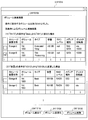
- FIGS. 25, 26, and 27 are diagrams illustrating a configuration example of a user interface of the unnecessary resource specifying program 4130 in the embodiment of the present invention.
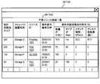
- FIG. 25 corresponds to a user interface for displaying a list of unnecessary resource candidates.
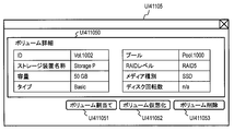
- FIG. 26 corresponds to a user interface that displays detailed information of unnecessary resource candidates.
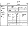
- FIG. 27 corresponds to a user interface for displaying unnecessary resource information in the resource list display.
- a user interface UI 41104 for displaying a list of unnecessary resource candidates includes an unnecessary resource candidate list UI411040 as a constituent element.
- the unnecessary resource candidate list UI411040 includes a condition non-applicable score, a storage device name, a resource ID, a condition applicable final date, and a ratio of the condition non-applicable reason.
- the user interface UI 41104 that displays a list of unnecessary resource candidates is not limited to the expression shown in FIG. 25, and may display other information indicating the degree and reason for not using the resource, or other information indicating the attribute of the resource. Good.
- the user interface in FIG. 25 is displayed by the process in step S3060 in FIG.
- the resource ID displayed in the unnecessary resource candidate list UI411040 is a link for displaying the detailed information of the resource.
- the user interface of FIG. 26 is displayed.
- FIG. 26 is displayed by pressing the link set to the resource ID of the resource (ie, logical volume) indicated by “Vol. 1002” in the unnecessary resource candidate list UI411040 of FIG. A user interface for displaying detailed information of a logical volume is shown.
- a user interface UI 41105 that displays detailed information of unnecessary resource candidates includes an area UI 411050 that displays detailed information of a volume, a button UI 411051 that instructs the host computer to assign a logical volume, and a virtualized virtual volume. And a button UI 410553 for instructing to delete a logical volume, and a button UI 410553 for instructing to delete a logical volume.
- the user interface UI 41105 that displays detailed information on unnecessary resource candidates is not limited to the expression in FIG. 26, and may display other detailed information on unnecessary resource candidates. Further, the user interface UI 41105 for displaying detailed information on unnecessary resource candidates may have a button for instructing execution of another setting operation for the unnecessary resource candidates.
- FIG. 27 shows an example of logical volume list display as an example of a user interface for displaying unnecessary resource information in the resource list display.
- a user interface UI 41106 for displaying information on unnecessary resources in the resource list display includes an area UI 411060 indicating a list of storage apparatuses, an area UI 411061 indicating information on storage apparatuses, and an area UI 411062 indicating a list of logical volumes. ,have.
- a storage device list area UI41060 is an area for displaying a list of all storage apparatuses under the management of the configuration management program 4110, and one of them can be selected.
- FIG. 27 shows a state where “Storage P” is selected.
- the area UI410661 indicating the storage apparatus information is an area for displaying information on the storage apparatus selected in the area UI411060 indicating the list of storage apparatuses.
- the information to be displayed is not limited to the expression in FIG. 27, and other information regarding the storage apparatus may be displayed.
- the area UI410662 indicating a list of logical volumes is an area for displaying a list of logical volumes possessed by the storage apparatus selected in the area UI411060 indicating the list of storage apparatuses.
- the area UI410662 indicating a list of logical volumes has attributes (ID, type, capacity) of the logical volume, but is not limited thereto, and may have other attributes of the logical volume.
- the area UI410662 showing a list of logical volumes has a condition non-applicable score, but is not limited to this, and has other information related to the degree of non-use of resources, such as the ratio of reason for non-applicability of the condition. May be.
- the management computer searches for available resources that match the conditions specified by the user (administrator) from the resources of the storage device, the resources that match the conditions For the resource that does not meet the condition, the cumulative number of times and the condition that the resource did not satisfy are recorded. Furthermore, the administrator calculates a score indicating the degree to which each resource does not easily meet the conditions specified by the user based on such information.
- the score may be based on the total number of times that the resource did not meet the condition, or based on the number of conditions that the resource did not satisfy. In addition, for resources that meet the conditions but are determined to be unusable due to temporary factors such as storage failures, the score may be adjusted so that it is not difficult to meet the conditions specified by the user. Good. Furthermore, when calculating the score based on the number of conditions that the resource did not satisfy, it may be calculated using different weights for the condition that must be specified and an arbitrary condition, and the ease with which each condition is satisfied You may calculate according to (the number of resources which satisfy
- the management computer determines a resource that does not meet the condition within a predetermined period before the current date and time, and a score indicating the degree of difficulty in meeting the condition for the resource, The condition that the resource is not satisfied is presented to the user. By doing so, it is possible to specify a resource that does not easily match the condition specified by the user, and further to specify a condition that does not easily match the resource.
- the target managed by the management software is not limited to the storage device, and may include a host computer, a switch, a hub, an application program that operates on the host computer, and the like.
- the management computer gives the user a score indicating the degree to which the resource is difficult to meet the condition and the condition that the resource is not satisfied via the user interface related to the list display of the resource that does not meet the condition specified by the user.
- a target for example, a logical volume
- the management computer responds to the selection operation via the detail display user interface.
- the detailed configuration information of the resource is displayed on the display screen.
- the management computer displays a list of resources on the display screen via the user interface related to resource list display, a score indicating the degree to which the resource is difficult to meet the condition and a condition that the resource is not satisfied To the user. In this way, it is possible to provide the administrator with easy-to-see resources that do not easily meet the conditions specified by the user.
- the management computer may determine an unnecessary resource candidate according to a condition different from the above condition non-applicable period. For example, the management computer may determine unnecessary resource candidates based on the number of times the condition is not met. Unnecessary resource candidates may be determined on the condition that the number of consecutive times that does not meet the condition reaches a threshold value, or that the number of times that the condition does not apply reaches a threshold value in a predetermined number of determinations.
- the management computer may compare the score with a threshold and determine an unnecessary resource candidate based on the comparison result.
- the threshold value specified in the determination of the unnecessary resource candidate is a fixed value or a fluctuation value.
- the management computer may execute the flow of FIG. 16 and subsequent steps in response to an event different from the search for the free resource corresponding to the search condition, for example, when a predetermined time comes.
- the management computer need not calculate the penalty value if unnecessary.
- FIG. 28 is a diagram showing a schematic configuration of a computer system 200 according to the second embodiment of the present invention.
- the computer system 200 includes a storage device 1000, a host computer 2000, a switch device 3000, a management computer 4000b, a switch device 5000, and a second storage device 6000.
- the difference from the computer system 100 shown in FIG. 1 is that the configuration management program 4110b of the management computer 4000b has a different processing sequence when searching for free resources, and the unnecessary resource identification program 4130b of the management computer 4000b is unnecessary. This is because the processing sequence when specifying the resource is different and the configuration of the unnecessary resource specifying table group 4140b of the management computer 4000b is different.
- FIG. 29 is a diagram illustrating a configuration example of an unnecessary resource specifying table group 4140b according to the second embodiment.
- the difference between the unnecessary resource specifying table group 4140 shown in FIG. 13 and the unnecessary resource specifying table group 4140b shown in FIG. 29 is that the unnecessary resource specifying table group 4140b is different from the management operation execution frequency table 4142b in each management operation. This is a point having a condition non-applicable number of times table 4143b and an unnecessary resource determination threshold value table 4144b.
- FIG. 30 is a diagram illustrating a configuration example of the management operation execution frequency table 4142b according to the second embodiment.
- the management operation execution frequency table 4142b includes a management operation ID 4142b0 for identifying a management operation executed by the user via the configuration management program 4110, a management operation name 4142b1, a management operation execution count 4142b2, and a management operation execution rate. 4142b3 as a configuration item.
- the management operation execution rate 4142b3 is a value indicating the ratio of the number of executions of each management operation 4142b2 to the total number of executions 4142b2 of all management operations stored in the management operation execution frequency table 4142b. .
- FIG. 31 is a diagram illustrating a configuration example of the condition non-applicable number table 4143b for each management operation according to the second embodiment.
- the condition non-applicable count table 4143b for each management operation includes a resource ID 4143b0 for identifying a resource included in the storage apparatus 1000 or the second storage apparatus 6000, and a search for a free resource accompanying the execution of the management operation.
- a condition non-applicable number 4143b1 for each management operation indicating the number of times each resource does not match the condition.
- FIG. 32 is a diagram illustrating a configuration example of the unnecessary resource determination threshold table 4144b according to the second embodiment.
- the unnecessary resource determination threshold value table 4144b includes an unnecessary resource determination threshold value 4144b0 that is a threshold value for determining a resource that hardly meets the condition specified by the user.
- FIG. 33 is a flowchart for explaining processing when the configuration management program 4110b searches for a free resource from the resources of the storage apparatus 1000 and the second storage apparatus 6000 in the second embodiment.
- step S4000 the configuration management program 4110b receives a free resource search request from the user via the user interface.
- step S4010 the configuration management program 4110b compares the configuration information table group 4120 with the search condition input by the user, and matches the condition from the free resources and the status is “normal”. Get resource information.
- the configuration management program 4110b refers to the condition non-applicable resource information table 4141 for the resource that does not meet the condition in step S4010, and the condition non-applicable reason count 41413 corresponding to the condition not satisfied. Is incremented. Also, the configuration management program 4110b stores the current date and time in the condition applicable last date and time 4112 for the resource that matches the condition in step S4010.
- step S4030 the configuration management program 4110b determines whether there is information on one or more resources acquired in step S4010. When information on one or more resources exists (YES in step S4030), the configuration management program 4110b moves to step S4040. If information on one or more resources does not exist (NO in step S4030), the configuration management program 4110b moves to step S4070.
- step S4030 If it is determined in step S4030 that there is one or more resource information (YES in step S4030), the resource management result obtained in step S4010 by the configuration management program 4110b in step S4040 is the resource search result. As displayed through the user interface.
- step S4050 the configuration management program 4110b executes a management operation using the free resource obtained as a search result.
- management operations include a process of assigning a logical volume to a host computer, but are not particularly limited. Further, since this process is performed using a general storage management function of the configuration management program 4110b, description thereof is omitted.
- step S4060 the configuration management program 4110b increments the corresponding value of the execution count 4142b2 of the management operation execution frequency table 4142b for the management operation executed in step S4010.
- step S4070 the configuration management program 4110b updates the condition non-applicable number table 4143b for each management operation for the resource that does not match the condition in step S4010. That is, the configuration management program 4110b increments the item of the condition non-applicable number 4143b1 for each management operation corresponding to the management operation executed in step S4010.
- step S4080 the configuration management program 4110b executes an unnecessary resource determination threshold update process. Details of this processing will be described later.
- step S4090 the configuration management program 4110b executes a condition non-applicable score calculation process considering the execution frequency of the management operation. This process will also be described later.
- the configuration management program 4110b completes the process of searching for a free resource from the resources of the storage device 1000 and the second storage device 6000.
- FIG. 34 is a flowchart for explaining processing in which the configuration management program 4110b updates the unnecessary resource determination threshold in the second embodiment.
- the configuration management program 4110b refers to the management operation execution frequency table 4142b and calculates a value obtained by dividing the number of executions 4142b2 for each management operation by a predetermined constant (for example, 2) for all management operations. .
- step S5010 the unnecessary resource determination threshold (t) is calculated from the following formula using the value calculated by the configuration management program 4110b in step S5000.
- Xi is the value calculated in step S5000 for the management operation i
- Yi is the value of the execution ratio 4142b3 corresponding to the management operation i.
- step S5020 the configuration management program 4110b stores the value calculated in step S5010 in the unnecessary resource determination threshold value 4144b0 of the unnecessary resource determination threshold value table 4144b.
- the configuration management program 4110b completes the processing for updating the unnecessary resource determination threshold.
- FIG. 35 is a flowchart for explaining processing when the configuration management program 4110b calculates the condition non-applicable score 41411 in consideration of the execution frequency of the management operation in the second embodiment.
- step S6000 the configuration management program 4110b calculates a condition non-applicable score (s) for the resource determined not to meet the condition in step S4010 from the following formula.
- Xi is the condition non-applicable number 4143b1 for the management operation i
- Yi is the execution ratio 4142b3 corresponding to the management operation i.
- the unnecessary resource determination threshold (t) In the process of calculating the unnecessary resource determination threshold (t) described above, if the predetermined constant is 2, the condition non-relevance when the condition non-applicable count for each management operation is exactly half the search execution count. The corresponding score (s) is set as an unnecessary resource determination threshold value (t).
- step S6020 the configuration management program 4110b updates the condition non-applicable score 41411 of the condition non-applicable resource information table 4141 with the value calculated in step S6000.
- the processing in which the configuration management program 4110b calculates the condition non-applicable score 41411 in consideration of the execution frequency of the management operation in the second embodiment is completed.
- the resource that does not match the condition in the free resource search performed in association with the management operation with high execution frequency has a lower execution frequency.
- the condition non-applicable score 41411 can be made higher than the resource that does not meet the condition in the free resource search performed in accordance with the management operation.
- FIG. 36 illustrates a case where the unnecessary resource identification program 4130b identifies a resource that does not substantially meet the conditions specified by the user from among the resources of the storage apparatus 1000 and the second storage apparatus 6000 in the second embodiment. It is a flowchart for demonstrating the example of the process of. Since most of the processing in FIG. 36 is the same as the processing in FIG. 24, differences from the processing in FIG. 16 will be described.
- step S3005b from the records acquired by the unnecessary resource identification program 4130b in step S3000, records whose condition non-applicable score 41411 is smaller than the unnecessary resource determination threshold 4144b0 of the unnecessary resource determination threshold table 4144b are excluded.
- the management computer performs a management operation when performing a management operation (for example, an operation for allocating a logical volume to a host computer) using an available resource that matches a condition specified by the user. Record the execution frequency of. Also, the management computer records the number of times for each type of management operation for resources that do not meet the conditions.
- a management operation for example, an operation for allocating a logical volume to a host computer
- the management computer calculates a score indicating the degree to which the resource does not easily meet the condition by using the number of times the resource does not meet the condition for each type of management operation and the execution frequency of the management operation.
- FIG. 37 is a diagram showing a schematic configuration of a computer system 300 according to the third embodiment of the present invention.
- the computer system 300 includes a storage device 1000, a host computer 2000, a switch device 3000, a management computer 4000c, a switch device 5000, and a second storage device 6000.
- FIG. 1 differs from the computer system 100 shown in FIG. 1 in that the processing sequence of the unnecessary resource specifying program 4130c of the management computer 4000c is different and that the management computer 4000c has a management authority information table group 4150c.
- FIG. 38 is a diagram illustrating a configuration example of the management authority information table group 4150c according to the third embodiment.
- the management authority information table group 4150c includes a user information table 4151c, a resource group information table 4152c, a resource / resource group correspondence information table 4153c, and a user / resource group correspondence information table 4154c.
- the user information table 4151c is a table for storing user (administrator) information.
- the resource group information table 4152c is a table that stores information on resource groups of the storage apparatus 1000 and the second storage apparatus 6000.
- the resource / resource group correspondence information table 4153c is a table that stores information about the correspondence relationship between the resources of the storage apparatus 1000 and the second storage apparatus 6000 and the resource group.
- the user / resource group correspondence information table 4154c is a table that stores information related to the correspondence relationship between the user (administrator) and the resource group.
- FIG. 39 is a diagram illustrating a configuration example of the user information table 4151c according to the third embodiment.
- the user information table 4151c includes a user ID 4151c0 for identifying the user and a higher user ID 4151c1 for identifying the higher user assigned to the user as configuration items.
- a higher-level user is a user who has higher management authority than other users. For example, an operation for classifying resources of the storage apparatus 1000 and the second storage apparatus 6000 into several resource groups is performed by a higher-level user, and a user for managing each resource group is assigned to each resource group.
- the user information table 4151c is not limited to the expression in FIG. 39, and may hold other information related to the user (administrator).
- FIG. 40 is a diagram illustrating a configuration example of the resource group information table 4152c according to the third embodiment.
- the resource group information table 4152c has a resource group ID 4152c0 for specifying a resource group as a configuration item. Note that the resource group information table 4152c is not limited to the expression of FIG. 40, and may hold other information related to the resource group.
- FIG. 41 is a diagram showing a configuration example of a resource / resource group correspondence information table 4153c according to the third embodiment.
- the resource / resource group correspondence information table 4153c includes, as configuration items, a resource group ID 4153c0 for identifying a resource group and a resource ID 4153c1 for identifying a resource. Note that the resource / resource group correspondence information table 4153c is not limited to the expression in FIG. 41, and may hold other information related to the correspondence between resources and resource groups.
- FIG. 42 is a diagram illustrating a configuration example of a user / resource group correspondence information table 4154c according to the third embodiment.
- the user / resource group correspondence information table 4154c includes a resource group ID 4154c0 for identifying a resource group and a user ID 4154c1 for identifying a user as configuration items.
- the user / resource group correspondence information table 4154c is not limited to the expression shown in FIG. 42, and may hold other information related to the correspondence relationship between resource groups and users.
- FIG. 43 shows the processing when the unnecessary resource specifying program 4130c in the third embodiment specifies a resource that hardly matches the condition specified by the user from among the resources of the storage apparatus 1000 and the second storage apparatus 6000. It is a flowchart for demonstrating. Since most of the processing in FIG. 43 is the same as the processing in FIG. 24, differences from the processing in FIG. 24 will be described.
- step S3000c the unnecessary resource identification program 4130c targets only the resources belonging to the resource group associated with the user operating the management computer, and the condition applicable last date and time of the condition non-applicable resource information table 4141. 41414 is compared with the current date and time, and a record whose difference is longer than a predetermined period is obtained.
- step S3050 if it is determined in step S3050 that the process of step S3040 has been executed once or more (“YES” in step S3050), the unnecessary resource specifying program 4130c proceeds to step S3060c.
- step S3060c the unnecessary resource specifying program 4130c executes an unnecessary resource display process considering the resource group. This process will be described later.
- FIG. 44 shows a process when the unnecessary resource specifying program 4130c in the third embodiment displays a resource that hardly matches a condition specified by the user from among the resources of the storage apparatus 1000 and the second storage apparatus 6000 ( It is a flowchart for demonstrating step S3060c).
- the unnecessary resource specifying program 4130c refers to the resource information acquired in step S3020 and the resource / resource group correspondence information table 4153c, and acquires information on users associated with the resource.
- step S7010 the unnecessary resource specifying program 4130c determines whether or not the corresponding resource is associated with a plurality of different users. If a plurality of different users are associated (step S7010: YES), the process proceeds to step S7030. If a plurality of different users are not associated (step S7010: NO), the process proceeds to step S7020.
- step S7020 the unnecessary resource specifying program 4130c sets the user operating the management computer 4000c as a display target of unnecessary resource information.
- the unnecessary resource identification program 4130c refers to the user information table 4151c, and acquires information on the higher-level users assigned to the corresponding plurality of users.
- step S7040 the unnecessary resource specifying program 4130c determines whether or not a common upper user is assigned to the corresponding user. If a common upper user is assigned (step S7040: YES), the process moves to step S7060. If a common upper user is not assigned (step S7040: NO), the process proceeds to step S7050.
- step S7050 the unnecessary resource specifying program 4130c sets all the plurality of users acquired in step S7000 as display targets of unnecessary resource information.
- step S7060 the unnecessary resource specifying program 4130c sets the common higher-order user acquired in step S7030 as a display target of unnecessary resource information.
- step S7070 the unnecessary resource identification program 4130c displays the resource information acquired in step S3020 and the ratio calculated in step S2040 to the display target user via the user interface.
- the unnecessary resource specifying program 4130c considers the resource group, and the resource hardly matches the condition specified by the user from among the resources of the storage apparatus 1000 and the second storage apparatus 6000. This information can be shown to the user.
- the management computer includes information on a user who uses the management computer, information on a higher-level user having higher management authority for the user, and information on a resource on which the user has management authority. Have. Based on these pieces of information, the management computer determines a target user to present resource information that does not easily meet the conditions specified by the user.
- the user when a single user has management authority for a resource that does not meet the conditions, the user is designated as the information presentation user, and for a resource that does not meet the conditions. If multiple users have administrative authority, specify the upper user of the user, and if there is a higher user, select the higher user as the information target user and there is no higher user.
- the plurality of users are information presentation target users.
- FIG. 45 is a diagram showing a schematic configuration of a computer system 400 according to the fourth embodiment of the present invention.
- the computer system 400 includes a storage device 1000, a host computer 2000, a switch device 3000, a management computer 4000d, a switch device 5000, and a second storage device 6000.
- FIG. 46 is a flowchart for explaining an example of processing when the configuration management program 4110d searches for a free resource from the resources of the storage apparatus 1000 and the second storage apparatus 6000 in this embodiment. Many of the processes in FIG. 46 are the same as the processes in FIG. 16, and only the differences from the processes in FIG. 16 will be described.
- step S2030 if it is determined in step S2030 that there is no more information about one resource acquired in step S2010, the configuration management program 4110d moves to step S2060d.
- step S2060d the configuration management program 4110d changes each condition to “ANY” for a part or all of the search conditions, and re-executes the free resource search.
- the search is re-executed on condition that it is within ⁇ r [%] of the original value (r is a predetermined constant).
- step S2070d the configuration management program 4110d sends information indicating that there is no resource that matches the condition input in step S2000, and the search condition and result executed in step S2050 via the user interface. indicate.
- FIG. 47 is a diagram illustrating a configuration example of a user interface of the configuration management program 4110d according to the fourth embodiment.
- FIG. 47 corresponds to a user interface showing search results for logical volumes.
- the user interface UI 41101d indicating the search result of the logical volume has an area UI 41110d indicating the search result of the logical volume, a button UI 4110111 instructing to allocate a logical volume to the host computer, and virtualizing the logical volume. It has a button UI411012d for instructing and a button UI4111013d for instructing deletion of the logical volume as components.
- the area UI41010d indicating the search result of the logical volume re-executes a free resource search by changing a part or all of the search condition and a message indicating that there is no resource that matches the condition input by the user. It has the area which shows the result.
- the area UI41010d indicating the search result of the logical volume is not limited to the expression shown in FIG. 47, and information indicating that there is no resource that matches the condition input by the user and a part or all of the search condition are changed and re-executed. Other information indicating the result of the executed free resource search may be displayed. Further, the area UI411010d indicating the search result of the logical volume may have a button for instructing execution of another setting operation for the logical volume.
- ⁇ Summary> when the management computer searches for available resources that match the conditions specified by the user (administrator) from the resources of the storage device, the resources that match the conditions are not found.
- the search condition when each condition is not specified or the value specified for each condition is changed within a predetermined range for some or all of the specified one or more conditions when they do not exist The resource search is performed again using the search conditions (hereinafter referred to as neighborhood conditions).
- the management computer displays, via the user interface related to the display of search results, information indicating that there are no available resources that match the conditions specified by the user, as well as the proximity conditions and the results of resource search based on the proximity conditions. indicate.
- the user can easily find a resource that can be used as an alternative, and thus the resource utilization efficiency of the storage apparatus can be improved.
- FIG. 48 is a diagram showing a schematic configuration of a computer system 500 according to the fifth embodiment of the present invention.
- the computer system 500 includes a storage device 1000, a host computer 2000, a switch device 3000, a management computer 4000e, a switch device 5000, and a second storage device 6000.
- FIG. 1 differs from the computer system 100 shown in FIG. 1 in that the processing sequence of the unnecessary resource identification program 4130e of the management computer 4000e is different and that the management computer 4000e has a frequent condition table group 4160e.
- FIG. 49 is a diagram illustrating a configuration example of a frequent appearance condition table group 4160e according to the fifth embodiment.
- the frequent condition table group 4160e includes a volume frequent condition table 4161e, a pool frequent condition table 4162e, and a physical resource frequent condition table 4163e.
- the volume frequent appearance condition table 4161e is a table for storing conditions that have been specified in the free resource search for the logical volume.
- the pool frequent appearance condition table 4162e is a table for storing conditions that have been specified in the search for free resources related to the pool.
- the physical resource frequent appearance condition table 4163e is a table for storing conditions that have been specified in the free resource search for physical resources.
- FIG. 50 is a diagram illustrating a configuration example of the volume frequent appearance condition table 4161e according to the fifth embodiment.
- the volume frequent appearance condition table 4161e includes a condition ID 4161e0 for identifying a condition, a condition 4161e1, a condition designation count 4161e2 indicating the number of times the condition is designated, and a condition when the search is executed with the condition designated. It has a resource shortage rate 4161e3 indicating the rate at which no matching resource was found as a configuration item.
- the condition 4161e1 is not limited to the expression in FIG. 50, and may be any condition for searching for a logical volume.
- FIG. 51 is a diagram illustrating a configuration example of a pool frequent appearance condition table 4162e according to the fifth embodiment. Since the configuration of the pool frequent appearance condition table 4162e is the same as the configuration of the volume frequent appearance condition table 4161e, description thereof is omitted.
- FIG. 52 is a diagram illustrating a configuration example of the physical resource frequent appearance condition table 4163e in the fifth embodiment.
- the configuration of the physical resource frequent appearance condition table 4163e is the same as the configuration of the volume frequent appearance condition table 4161e, and a description thereof will be omitted.
- FIG. 53 shows an example in which the unnecessary resource identification program 4130e identifies a resource that does not substantially match the conditions specified by the user from among the resources of the storage apparatus 1000 and the second storage apparatus 6000 in the fifth embodiment. It is a flowchart for demonstrating a process. Since most of the processing in FIG. 53 is the same as the processing in FIG. 24, differences from the processing in FIG. 24 will be described.
- step S3050 when it is determined in step S3050 that the process of step S3040 has been executed one or more times, the unnecessary resource specifying program 4130e proceeds to step S3055e.
- step S3055e the unnecessary resource specifying program 4130e executes a countermeasure selection process for the unnecessary resource. The contents of this process will be described later.
- step S3060e the unnecessary resource identification program 4130e displays the information on the corresponding resource, the ratio calculated in step S3040, and the countermeasure selected in step S3055e via the user interface.
- the configuration management program 4110 may automatically execute the countermeasure selected in step S3055e.
- FIG. 54 illustrates a process when the unnecessary resource identification program 4130e selects a measure for improving resource utilization efficiency for a resource that hardly meets the condition specified by the user in the fifth embodiment. It is a flowchart for doing.
- the resource ID 41410 of the non-conditional resource information table 4141 is compared with the volume ID 41220 of the volume information table 4122 and the IDs of the resource and the storage device match.
- the record is identified by acquiring the storage ID 41221 of the volume information table 4122.
- resources such as pools and physical resources.
- step S8010 the unnecessary resource identification program 4130e divides the total value of items indicating the reason based on the physical characteristics of the resource in the condition non-applicable reason count 41413 by the total value of all items in the condition non-applicable reason count 41413. To calculate the ratio.
- step S8020 the unnecessary resource identification program 4130e determines whether the ratio calculated in step S8010 exceeds a predetermined threshold. If it exceeds the threshold, the process proceeds to step S8030. If the threshold is not exceeded, the process proceeds to step S8090.
- the unnecessary resource identification program 4130e refers to the configuration information table group 4120 and calculates the total number of each type of resource (logical volume, pool, physical resource, etc.) for each storage device.
- step S8040 the unnecessary resource specifying program 4130e counts the number of resources acquired in step S3000 in FIG. 53 for each storage device.
- step S8050 the unnecessary resource identification program 4130e calculates the ratio of the number calculated in step S8040 to the number calculated in step S8030.
- step S8060 the unnecessary resource identification program 4130e determines whether the ratio calculated in step S8050 exceeds a predetermined threshold. If it exceeds the threshold, the process proceeds to step S8070. If the threshold is not exceeded, the process proceeds to step S8080.
- step S8070 the unnecessary resource identification program 4130e selects discarding the storage device as a countermeasure.
- step S8080 the unnecessary resource identification program 4130e selects to discard the physical resource constituting the resource acquired in step S3000 of FIG. 53 as a countermeasure. If the resource acquired in step S3000 in FIG. 53 is a physical resource itself, discarding it may be a countermeasure.
- the unnecessary resource identification program 4130e refers to the physical resource frequent appearance condition table 4163e, calculates the value obtained by dividing the value of the condition designation count 4163e2 by the value of the resource shortage rate 4163e3, and divides the value by the constant 100.
- the “capacity”, “media type”, and “disk rotation speed” of the condition 4163e1 are acquired, and the physical resources that match the “capacity”, “media type”, and “disk rotation speed” are discarded.
- Introducing instead of physical resources may be added as a countermeasure.
- step S8090 the unnecessary resource identification program 4130e executes a resource remake determination process. The contents of this process will be described later.
- step S8100 the unnecessary resource identification program 4130e selects, as a countermeasure, the resource that has not been recreated in step S8090 among the resources acquired in step S3000 of FIG. 53 as a countermeasure. .
- the unnecessary resource specifying program 4130e completes the process of selecting a measure for improving the resource utilization efficiency for the resource that does not substantially match the condition specified by the user.
- steps S8090 and S8100 are omitted, or steps S8030 to S8080 are omitted.
- FIG. 55 shows another configuration of the resource according to the fifth embodiment as a measure for the unnecessary resource identification program 4130e to improve the utilization efficiency of the resource for the resource that hardly meets the condition specified by the user.
- 10 is a flowchart for explaining processing (step S8090) when it is determined that the resource is remade.
- step S9000 the unnecessary resource identification program 4130e refers to the table group 4150e, and acquires a record in which both the condition designation count and the resource shortage rate exceed a predetermined threshold.
- step S9010 the unnecessary resource specifying program 4130e determines whether or not the corresponding record exists. If a record exists (step S9010: YES), the process moves to step S9020. If there is no record (step S9010: NO), this flow ends.
- step S9020 the unnecessary resource specifying program 4130e compares the information acquired in step S9000 with the resource information acquired in step S3000 of FIG.
- step S9030 it is determined whether there is a resource that can be recreated as a resource that satisfies the condition acquired in step S9000 among the resources acquired in step S3000 of FIG.
- step S9040 If there is no resource that can be recreated in the resource that satisfies the condition acquired in step S9000 (step S9030: NO), this flow ends.
- step S9040 the unnecessary resource specifying program 4130e selects a resource necessary for creating a resource that satisfies the condition acquired in step S9000 from the resource information acquired in step S3000 of FIG.
- step S9050 the unnecessary resource specifying program 4130e selects as a countermeasure to remake the resource selected in step S9040 into the resource that satisfies the condition acquired in step S9000.
- the unnecessary resource identification program 4130e recreates the resource as a resource having a different configuration as a measure for improving the resource utilization efficiency for the resource that does not substantially meet the condition specified by the user. Is completed.
- Example of recreating a logical volume into a large-capacity logical volume The unnecessary resource identification program 4130e targets all logical volume information acquired in step S3000 in FIG. In the non-applicable reason count 41413, all pieces of logical volume information (hereinafter referred to as remodeling target volume information) having the largest value in the item “capacity is small” are extracted.
- remodeling target volume information all pieces of logical volume information (hereinafter referred to as remodeling target volume information) having the largest value in the item “capacity is small” are extracted.
- the unnecessary resource specifying program 4130e refers to the configuration information table group 4120, and extracts all the information of the logical volume whose type is “Basic” from the remodeling target volume information. Further, the unnecessary resource identification program 4130e refers to the configuration information table group 4120, and groups the information of the corresponding volume so that the storage ID, pool ID, RAID level, media type, and disk rotation speed are the same. Finally, the unnecessary resource identification program 4130e recreates all or part of the logical volume for each group into a logical volume with a large capacity.
- An unnecessary resource specifying program 4130e refers to a pool frequent appearance condition table 4162e, and a condition for a pool whose condition 4162e1 has a value of “Automated Tiering” A value obtained by multiplying the value of the designated number of times 4162e2 by the value of the resource shortage rate 4162e3 and dividing by the constant 100 is calculated, and the “RAID level”, “media” of the pool with the largest value (hereinafter referred to as the capacity expansion target pool) "Type" and "disk rotation speed" are acquired.
- the unnecessary resource specifying program 4130e matches the “RAID level”, “media type”, and “disk rotation number” of the capacity expansion target pool from the information of all the logical volumes acquired in step S3000 of FIG. Get information on all logical volumes to be used. Finally, the unnecessary resource specifying program 4130e recreates all or part of the corresponding logical volume into the free capacity of the capacity expansion target pool.
- a method of adding a logical volume to a pool as a method of recreating a logical volume into free capacity of a capacity expansion target pool. If the pool is a storage device that consists of physical resources, delete the logical volume, delete the pool from which the logical volume was cut out, and change the physical resources (physical storage areas) that make up the pool to There is a method to add to the capacity expansion target pool.
- the pool may not be deleted because another logical volume has been extracted from the pool from which the logical volume was extracted.
- the corresponding pool can be deleted after another logical volume is migrated to another pool using the volume migration function of the storage apparatus.
- the volume migration function is a function for migrating data stored in a logical volume to another logical volume without changing the I / O access path setting in a host computer that uses the logical volume of the storage device. .
- the volume migration function first copies data from one logical volume to another logical volume, and deletes the data of the copy source logical volume.
- the address management of the storage device handles address management of copy source and copy destination data.
- the access processing program provides the host with the address data managed by the address management program.
- the write data is held in the cache memory, and the data is later written in the migration destination logical volume.
- the logical volume replacement is realized by performing the above processing.
- the storage virtualization program 1213 of the storage device 1000 is used. There is a method of virtualizing the logical volume 6110 of the second storage apparatus 6000 in the storage apparatus 1000 and adding the capacity to the capacity expansion target pool.
- FIG. 56 is a diagram showing a configuration example of a user interface of the unnecessary resource specifying program 4130e according to the fifth embodiment.
- FIG. 56 corresponds to a user interface for displaying detailed information on unnecessary resource candidates and measures for improving the resource utilization efficiency.
- the user interface shown in FIG. 56 is an extension of the user interface shown in FIG. 26 and displays measures for improving the resource utilization efficiency.
- the user interface shown in FIG. 56 can be called via the link set in the resource ID in the unnecessary resource candidate list UI411040 shown in FIG. 25, similarly to the user interface shown in FIG.
- the user interface UI 41105 for displaying a list of unnecessary resource candidates has an area UI 411050 showing details of the logical volume and an area UI 411054e showing measures for improving resource utilization efficiency.
- the user interface UI 41105 further includes, as components, a button UI 410551 for instructing to allocate a logical volume to the host computer, a button UI 410552 for instructing to virtualize the logical volume, and a button for instructing deletion of the logical volume.
- buttons UI411105 for instructing to allocate a logical volume to the host computer
- a button UI411052 for instructing to virtualize the logical volume
- an instruction to delete the logical volume Since the button UI411105 is the same as that in FIG. 26, the description thereof is omitted.
- the area UI411054e indicating a countermeasure for improving the resource utilization efficiency includes a button for selecting a countermeasure and an area indicating a countermeasure content as components. In the area indicating countermeasure contents, countermeasures determined to be executable by the processing shown in FIGS. 54 and 55 are displayed.
- a button UI411055e for instructing to execute the countermeasure shown in the area UI411054e indicating the countermeasure for improving the resource utilization efficiency is a countermeasure selected by the user in the area UI411054e indicating the countermeasure for improving the resource utilization efficiency. Is a button for instructing to be executed via the configuration management program 4110.
- the management computer counts the total number of times for each search condition specified by the user, and the ratio of resources that do not exist as a result of searching for resources based on the conditions, , Record. Based on these pieces of information, the management computer identifies resources that are frequently searched and often do not exist (hereinafter referred to as insufficient resources).
- the management computer determines measures for optimizing resource management costs and utilization efficiency based on resource information that does not easily meet the conditions specified by the user and information on insufficient resources. As a method for realizing this, for example, a resource that does not match the condition may be changed to a shortage resource, or a resource that does not match the condition may be deleted.
- one or more logical volumes that do not meet the conditions due to the small capacity may be deleted, and a new logical volume may be generated according to the capacity of the insufficient logical volume.
- the logical volume cut out from the pool may be deleted, or another physical resource released by deleting another pool may be added to the pool.
- a logical volume possessed by another storage device may be virtualized as the capacity of the storage device having the pool and added to the pool.
- the physical resource that constitutes the resource may be discarded. Furthermore, when such a resource occupies a large proportion of all resources of the storage device, the storage device may be discarded.
- the present invention can also be realized by a program code of software that realizes the functions of the embodiment.
- a storage medium in which the program code is recorded is provided to the system or apparatus, and the computer (or CPU or MPU) of the system or apparatus reads the program code stored in the storage medium.
- the program code itself read from the storage medium realizes the functions of the above-described embodiments, and the program code itself and the storage medium storing the program code constitute the present invention.
- a storage medium for supplying such program code for example, a flexible disk, CD-ROM, DVD-ROM, hard disk, optical disk, magneto-optical disk, CD-R, magnetic tape, nonvolatile memory card, ROM Etc. are used.
- an OS operating system
- the computer CPU or the like performs part or all of the actual processing based on the instruction of the program code.
- the program code is stored in a storage means such as a hard disk or memory of a system or apparatus, or a storage medium such as a CD-RW or CD-R
- the computer (or CPU or MPU) of the system or apparatus may read and execute the program code stored in the storage means or the storage medium when used.
- control lines and information lines are those that are considered necessary for the explanation, and not all control lines and information lines on the product are necessarily shown. All the components may be connected to each other.
Landscapes
- Engineering & Computer Science (AREA)
- Theoretical Computer Science (AREA)
- Physics & Mathematics (AREA)
- General Engineering & Computer Science (AREA)
- General Physics & Mathematics (AREA)
- Human Computer Interaction (AREA)
- Quality & Reliability (AREA)
- Information Retrieval, Db Structures And Fs Structures Therefor (AREA)
Priority Applications (2)
| Application Number | Priority Date | Filing Date | Title |
|---|---|---|---|
| US13/576,089 US20130198466A1 (en) | 2012-01-27 | 2012-01-27 | Computer system |
| PCT/JP2012/051853 WO2013111331A1 (fr) | 2012-01-27 | 2012-01-27 | Système informatique |
Applications Claiming Priority (1)
| Application Number | Priority Date | Filing Date | Title |
|---|---|---|---|
| PCT/JP2012/051853 WO2013111331A1 (fr) | 2012-01-27 | 2012-01-27 | Système informatique |
Publications (1)
| Publication Number | Publication Date |
|---|---|
| WO2013111331A1 true WO2013111331A1 (fr) | 2013-08-01 |
Family
ID=48871338
Family Applications (1)
| Application Number | Title | Priority Date | Filing Date |
|---|---|---|---|
| PCT/JP2012/051853 Ceased WO2013111331A1 (fr) | 2012-01-27 | 2012-01-27 | Système informatique |
Country Status (2)
| Country | Link |
|---|---|
| US (1) | US20130198466A1 (fr) |
| WO (1) | WO2013111331A1 (fr) |
Families Citing this family (7)
| Publication number | Priority date | Publication date | Assignee | Title |
|---|---|---|---|---|
| WO2014141363A1 (fr) * | 2013-03-11 | 2014-09-18 | 株式会社日立製作所 | Système de stockage et procédé de commande de système de stockage |
| TW201715431A (zh) * | 2015-10-29 | 2017-05-01 | 宇瞻科技股份有限公司 | 具網路認證功能之硬碟管理系統及其方法 |
| US9524111B1 (en) * | 2016-03-07 | 2016-12-20 | FittedCloud, Inc. | Devices, systems, apparatus, and methods for transparent and automated optimization of storage resource allocation in a cloud services system |
| CN106357913A (zh) * | 2016-09-28 | 2017-01-25 | 北京小米移动软件有限公司 | 信息提醒方法及装置 |
| CN110058963B (zh) * | 2018-01-18 | 2023-05-09 | 伊姆西Ip控股有限责任公司 | 用于管理存储系统的方法、设备和计算机程序产品 |
| CN108683652A (zh) * | 2018-05-04 | 2018-10-19 | 北京奇安信科技有限公司 | 一种基于行为权限的处理网络攻击行为的方法及装置 |
| US10983820B2 (en) * | 2019-03-06 | 2021-04-20 | International Business Machines Corporation | Fast provisioning of storage blocks in thin provisioned volumes for supporting large numbers of short-lived applications |
Citations (4)
| Publication number | Priority date | Publication date | Assignee | Title |
|---|---|---|---|---|
| JPH1185578A (ja) * | 1997-09-05 | 1999-03-30 | Fujitsu Ltd | ファイル管理装置とその動作を実行するためのプログラムを記載した記録媒体 |
| JP2002278806A (ja) * | 2001-03-16 | 2002-09-27 | Toshiba Information Systems (Japan) Corp | 不要ファイル管理装置、不要ファイル管理方法、及び不要ファイル管理プログラム |
| JP2009140356A (ja) * | 2007-12-07 | 2009-06-25 | Hitachi Ltd | 管理装置及び管理方法 |
| WO2011108027A1 (fr) * | 2010-03-04 | 2011-09-09 | 株式会社日立製作所 | Système informatique et procédé de commande associé |
Family Cites Families (2)
| Publication number | Priority date | Publication date | Assignee | Title |
|---|---|---|---|---|
| JP4307982B2 (ja) * | 2003-12-19 | 2009-08-05 | 株式会社日立製作所 | データ多重化制御方法 |
| US7849180B2 (en) * | 2008-04-29 | 2010-12-07 | Network Appliance, Inc. | Load balanced storage provisioning |
-
2012
- 2012-01-27 US US13/576,089 patent/US20130198466A1/en not_active Abandoned
- 2012-01-27 WO PCT/JP2012/051853 patent/WO2013111331A1/fr not_active Ceased
Patent Citations (4)
| Publication number | Priority date | Publication date | Assignee | Title |
|---|---|---|---|---|
| JPH1185578A (ja) * | 1997-09-05 | 1999-03-30 | Fujitsu Ltd | ファイル管理装置とその動作を実行するためのプログラムを記載した記録媒体 |
| JP2002278806A (ja) * | 2001-03-16 | 2002-09-27 | Toshiba Information Systems (Japan) Corp | 不要ファイル管理装置、不要ファイル管理方法、及び不要ファイル管理プログラム |
| JP2009140356A (ja) * | 2007-12-07 | 2009-06-25 | Hitachi Ltd | 管理装置及び管理方法 |
| WO2011108027A1 (fr) * | 2010-03-04 | 2011-09-09 | 株式会社日立製作所 | Système informatique et procédé de commande associé |
Also Published As
| Publication number | Publication date |
|---|---|
| US20130198466A1 (en) | 2013-08-01 |
Similar Documents
| Publication | Publication Date | Title |
|---|---|---|
| JP5502232B2 (ja) | ストレージシステム、及びその制御方法 | |
| JP4235220B2 (ja) | 計算機システムおよびデータ移行方法 | |
| JP4690765B2 (ja) | ストレージ管理システム、ストレージ管理サーバ、データ再配置制御方法およびデータ再配置制御プログラム | |
| JP5314772B2 (ja) | 性能の異なる実領域群で構成されたプールを有するストレージシステムの管理システム及び方法 | |
| US8918613B2 (en) | Storage apparatus and data management method for storage area allocation based on access frequency | |
| US8495331B2 (en) | Storage apparatus and storage management method for storing entries in management tables | |
| JP5661921B2 (ja) | 計算機システム及び管理システム | |
| JP5706531B2 (ja) | 計算機システム、及び情報管理方法 | |
| JP5079841B2 (ja) | ThinProvisioningに従う仮想的な論理ボリュームに対するデータのライトを制御する方法及びストレージ装置 | |
| JP4643395B2 (ja) | ストレージシステム及びデータの移動方法 | |
| US8578121B2 (en) | Computer system and control method of the same | |
| US8930621B2 (en) | Storage subsystem and storage control method | |
| WO2013111331A1 (fr) | Système informatique | |
| US20110197044A1 (en) | Storage system for reallocating data in virtual volumes and methods of the same | |
| JPWO2016121005A1 (ja) | 管理計算機および計算機システムの管理方法 | |
| JP2007072813A (ja) | ストレージシステム、ファイル移動方法、及びコンピュータプログラム | |
| JP2013114624A (ja) | ストレージシステム及びプール容量縮小の制御方法 | |
| JP2011186794A (ja) | ストレージシステム内のデータの配置を制御する管理システム、及び、データ配置制御方法 | |
| WO2013103005A1 (fr) | Dispositif de gestion et procédé de gestion pour système informatique | |
| CN110703995B (zh) | 存储系统架构及其访问数据的方法 | |
| JPWO2015198441A1 (ja) | 計算機システム、管理計算機、および管理方法 | |
| JP5421201B2 (ja) | 計算機システムを管理する管理システム及び管理方法 | |
| JP5425117B2 (ja) | 計算機システム、及びその管理方法、並びにプログラム | |
| CN107430527A (zh) | 具有服务器存储系统的计算机系统 | |
| JPWO2015107626A1 (ja) | 計算機システムおよびその階層記憶の制御方法 |
Legal Events
| Date | Code | Title | Description |
|---|---|---|---|
| WWE | Wipo information: entry into national phase |
Ref document number: 13576089 Country of ref document: US |
|
| 121 | Ep: the epo has been informed by wipo that ep was designated in this application |
Ref document number: 12866629 Country of ref document: EP Kind code of ref document: A1 |
|
| NENP | Non-entry into the national phase |
Ref country code: DE |
|
| 122 | Ep: pct application non-entry in european phase |
Ref document number: 12866629 Country of ref document: EP Kind code of ref document: A1 |
|
| NENP | Non-entry into the national phase |
Ref country code: JP |