WO2013111382A1 - Dispositif de disque optique - Google Patents
Dispositif de disque optique Download PDFInfo
- Publication number
- WO2013111382A1 WO2013111382A1 PCT/JP2012/074615 JP2012074615W WO2013111382A1 WO 2013111382 A1 WO2013111382 A1 WO 2013111382A1 JP 2012074615 W JP2012074615 W JP 2012074615W WO 2013111382 A1 WO2013111382 A1 WO 2013111382A1
- Authority
- WO
- WIPO (PCT)
- Prior art keywords
- recording
- optical disc
- signal
- layer
- spot
- Prior art date
- Legal status (The legal status is an assumption and is not a legal conclusion. Google has not performed a legal analysis and makes no representation as to the accuracy of the status listed.)
- Ceased
Links
Images


















Classifications
-
- G—PHYSICS
- G11—INFORMATION STORAGE
- G11B—INFORMATION STORAGE BASED ON RELATIVE MOVEMENT BETWEEN RECORD CARRIER AND TRANSDUCER
- G11B7/00—Recording or reproducing by optical means, e.g. recording using a thermal beam of optical radiation by modifying optical properties or the physical structure, reproducing using an optical beam at lower power by sensing optical properties; Record carriers therefor
- G11B7/08—Disposition or mounting of heads or light sources relatively to record carriers
- G11B7/09—Disposition or mounting of heads or light sources relatively to record carriers with provision for moving the light beam or focus plane for the purpose of maintaining alignment of the light beam relative to the record carrier during transducing operation, e.g. to compensate for surface irregularities of the latter or for track following
- G11B7/094—Methods and circuits for servo offset compensation
-
- G—PHYSICS
- G11—INFORMATION STORAGE
- G11B—INFORMATION STORAGE BASED ON RELATIVE MOVEMENT BETWEEN RECORD CARRIER AND TRANSDUCER
- G11B7/00—Recording or reproducing by optical means, e.g. recording using a thermal beam of optical radiation by modifying optical properties or the physical structure, reproducing using an optical beam at lower power by sensing optical properties; Record carriers therefor
- G11B7/08—Disposition or mounting of heads or light sources relatively to record carriers
- G11B7/09—Disposition or mounting of heads or light sources relatively to record carriers with provision for moving the light beam or focus plane for the purpose of maintaining alignment of the light beam relative to the record carrier during transducing operation, e.g. to compensate for surface irregularities of the latter or for track following
- G11B7/095—Disposition or mounting of heads or light sources relatively to record carriers with provision for moving the light beam or focus plane for the purpose of maintaining alignment of the light beam relative to the record carrier during transducing operation, e.g. to compensate for surface irregularities of the latter or for track following specially adapted for discs, e.g. for compensation of eccentricity or wobble
- G11B7/0956—Disposition or mounting of heads or light sources relatively to record carriers with provision for moving the light beam or focus plane for the purpose of maintaining alignment of the light beam relative to the record carrier during transducing operation, e.g. to compensate for surface irregularities of the latter or for track following specially adapted for discs, e.g. for compensation of eccentricity or wobble to compensate for tilt, skew, warp or inclination of the disc, i.e. maintain the optical axis at right angles to the disc
-
- G—PHYSICS
- G11—INFORMATION STORAGE
- G11B—INFORMATION STORAGE BASED ON RELATIVE MOVEMENT BETWEEN RECORD CARRIER AND TRANSDUCER
- G11B7/00—Recording or reproducing by optical means, e.g. recording using a thermal beam of optical radiation by modifying optical properties or the physical structure, reproducing using an optical beam at lower power by sensing optical properties; Record carriers therefor
- G11B7/004—Recording, reproducing or erasing methods; Read, write or erase circuits therefor
- G11B7/0045—Recording
-
- G—PHYSICS
- G11—INFORMATION STORAGE
- G11B—INFORMATION STORAGE BASED ON RELATIVE MOVEMENT BETWEEN RECORD CARRIER AND TRANSDUCER
- G11B7/00—Recording or reproducing by optical means, e.g. recording using a thermal beam of optical radiation by modifying optical properties or the physical structure, reproducing using an optical beam at lower power by sensing optical properties; Record carriers therefor
- G11B7/12—Heads, e.g. forming of the optical beam spot or modulation of the optical beam
- G11B7/135—Means for guiding the beam from the source to the record carrier or from the record carrier to the detector
- G11B7/1392—Means for controlling the beam wavefront, e.g. for correction of aberration
-
- G—PHYSICS
- G11—INFORMATION STORAGE
- G11B—INFORMATION STORAGE BASED ON RELATIVE MOVEMENT BETWEEN RECORD CARRIER AND TRANSDUCER
- G11B7/00—Recording or reproducing by optical means, e.g. recording using a thermal beam of optical radiation by modifying optical properties or the physical structure, reproducing using an optical beam at lower power by sensing optical properties; Record carriers therefor
- G11B7/24—Record carriers characterised by shape, structure or physical properties, or by the selection of the material
- G11B7/2403—Layers; Shape, structure or physical properties thereof
- G11B7/24035—Recording layers
- G11B7/24038—Multiple laminated recording layers
-
- G—PHYSICS
- G11—INFORMATION STORAGE
- G11B—INFORMATION STORAGE BASED ON RELATIVE MOVEMENT BETWEEN RECORD CARRIER AND TRANSDUCER
- G11B7/00—Recording or reproducing by optical means, e.g. recording using a thermal beam of optical radiation by modifying optical properties or the physical structure, reproducing using an optical beam at lower power by sensing optical properties; Record carriers therefor
- G11B7/24—Record carriers characterised by shape, structure or physical properties, or by the selection of the material
- G11B7/2403—Layers; Shape, structure or physical properties thereof
- G11B7/24047—Substrates
- G11B7/2405—Substrates being also used as track layers of pre-formatted layers
Definitions
- the present invention relates to an optical disc apparatus for reproducing information from an optical disc using a laser or recording information on the optical disc.
- a layer having a physical groove structure (hereinafter referred to as a servo layer) including addresses for addressing and tracking servo control is provided.
- Patent Document 1 proposes an optical disc composed of a layer (hereinafter referred to as a recording layer) that performs recording and reproduction without a physical groove structure called a groove structure.
- a recording layer a layer that performs recording and reproduction without a physical groove structure
- An optical disc in which the recording / reproducing layer does not have a physical groove structure is hereinafter referred to as a grooveless disc.
- Patent Document 1 states that, “After recording while following the guide track, the tilt state of the disc with respect to the optical axis of the irradiation beam has changed due to warpage due to the change of the disc over time or attachment to the device. When additional recording is performed while following the guide track, a deviation occurs between the recorded recording track and the recording track at the time of additional recording, as shown in FIG.
- Patent Document 1 states that “the additional recording start position following the recorded area in the recording layer of the guide layer separation type optical recording medium is detected and separated from the additional recording start position to the unrecorded area side at the start of additional recording.
- the irradiation spot of the first laser beam for servo By moving the irradiation spot of the first laser beam for servo to a position on the guide track opposite to the position, the irradiation spot on the recording layer of the second laser beam for recording or reproduction is moved to follow, and after the movement, “Additional recording on the recording layer is started from the irradiation spot position of the second laser beam”.
- Patent Document 2 “for tracking using a second spot while irradiating at least a first light spot and a second light spot on a disk-shaped optical recording medium and performing tracking using the first light spot.
- the technology for forming a mark or a guide groove is disclosed.
- FIG. 7B shows a case where servo areas 500 aligned in the radial direction are allocated, and a sample servo can be used for tracking.
- the address information is gray code or CAPA (Complementary Allocated Pit Address). Accordingly, there is a description that the spot interval between the tracks of the first light spot 121 is a half-integer multiple.
- Patent Document 3 has a problem that “the position accuracy in the radial direction can be improved when a plurality of mark layers are formed in the recording layer of the optical disk”. Then, as a means for solving the problem, “the optical disk apparatus 10 appropriately adjusts the optical paths of the servo light beam LS, the information light beam LM, and the tracking light beam LK in the optical path forming unit 70 of the optical pickup 17, and then the objective lens 18.
- the servo light beam LS, the information light beam LM, and the tracking light beam LK are condensed respectively, and the optical pickup 17 controls the focus of the objective lens 18 so that the servo light beam LS is focused on the reference layer 104, and By performing tracking control of the objective lens 18 so that the tracking light beam LK is focused on the reference track TE of the target mark layer YG, the focus FM of the information light beam LM condensed by the objective lens 18 is changed to the target mark layer YG. Can be matched to the target track TG " It has been described.
- the relative position of the light spot irradiated on the recording layer is shifted due to the deviation of the relative angle between the optical disc and the pickup in the radial direction. Due to this relative positional deviation, for example, there is a problem that overwriting of a mark already recorded at the time of additional recording occurs and data is lost.
- the optical disk recording / reproducing apparatus copes with variations in recording film characteristics and the like for each disk by performing a process called OPC (Optimum Power Power Control) for obtaining the optimum light intensity for recording.
- OPC Optimum Power Power Control
- recording is performed while changing the intensity of the laser beam in an OPC area provided on the disk, and a portion is recorded that deviates from the optimum light intensity.
- Patent Document 1 additional recording is started with a gap from the final recording position of the recorded area. Therefore, the light of each laser beam is caused by warpage due to aging of the optical disk, differences in recording devices, and the like. Even if there is a tilt (tilt) in the optical disc with respect to the axis, overwriting in the recorded area is suppressed.
- the solution of the above-mentioned Patent Document 1 has a problem that a wasteful area is formed every time additional recording is performed, resulting in a decrease in disk capacity.
- an object of the present invention is to provide an optical disc apparatus capable of appropriately performing additional recording on a grooveless disc.
- an optical disc apparatus capable of appropriately performing additional recording on a grooveless disc.
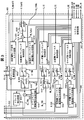
- FIG. 1 is a block configuration diagram showing an optical disc apparatus of Embodiment 1.
- FIG. FIG. 2 is a block configuration diagram illustrating a servo error signal generation circuit 104 according to the first embodiment.
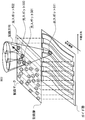
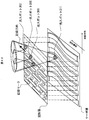
- 1 is a block configuration diagram illustrating a signal processing circuit 105 according to a first embodiment. It is a figure explaining the structure of the optical disk 102, and each laser spot.
- FIG. 6 is a diagram illustrating the function of a recording layer sub-spot R_SubLS of Example 1.
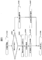
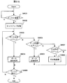
- 3 is a flowchart of a setup process according to the first embodiment.
- 3 is a flowchart of a recording process according to the first embodiment.
- 7 is a correspondence table showing the operating states of the tracking control system and the focus control system in various operating states and names defined in the present specification.
- FIG. 6 is a schematic diagram showing a laser spot on a recording layer when performing recording layer SubSpot tracking control according to Example 1; It is a schematic diagram showing a laser spot on the recording layer when the voltage V_TpAdj output from the recording layer track pitch adjustment voltage generation circuit is changed. It is a wave form diagram explaining R_MainTE signal at the time of changing voltage V_TpAdj which a recording layer track pitch adjustment voltage generation circuit outputs. It is a figure explaining the method of calculating the optimal value of the signal of each part in the middle of track pitch adjustment of a present Example, and voltage V_TpAdj. 10 is a flowchart of recording processing according to the second embodiment.
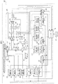
- FIG. 6 is a configuration diagram showing an optical disk device according to a fifth embodiment.
- FIG. 6 is a configuration diagram illustrating an optical disc device according to a sixth embodiment Image of change of optical axis due to change of angle of variable angle raising mirror of embodiment 6 Image diagram when the variable angle raising mirror rotates counterclockwise Waveform image diagram of error signal in optical disc apparatus of Examples 5 and 6
- FIG. 1 is a block diagram showing an embodiment of an optical disc apparatus according to the present invention.
- the optical disc apparatus 101 records or reproduces information by irradiating an optical disc 102 mounted on the apparatus with laser light, and communicates with a host 114 such as a PC (Personal Computer) through an interface such as SATA (Serial Advanced Technology Attachment). Do.
- a host 114 such as a PC (Personal Computer) through an interface such as SATA (Serial Advanced Technology Attachment).
- SATA Serial Advanced Technology Attachment
- the structure of the optical disk 102 is illustrated in FIG.
- the optical disk 102 has a servo layer having a track (guide groove) structure and N recording layers (N ⁇ 1, N is a natural number) not having a track structure.
- a track on the servo layer is referred to as a servo layer track.
- the pitch (interval) of the servo layer tracks is represented by Tp.
- Tp The pitch (interval) of the servo layer tracks.
- Tp The pitch (interval) of the servo layer tracks.
- S_LB indicates the laser beam irradiated on the servo layer
- R_LB indicates the laser beam irradiated on the recording layer.
- the objective lens 1311 generates two laser spots on the recording layer, that is, a recording layer main spot R_MainLS and a recording layer sub-spot R_SubLS. Also, a servo layer laser spot S_LS can be generated for the servo layer.
- the radial distance between the two laser spots R_MainLS and R_SubLS generated on the recording layer is arranged so as to be substantially equal to the track pitch Tp of the servo layer.
- FIG. 5 shows the positional relationship between the optical disc 102 and each laser spot when information is additionally recorded on the optical disc 102.
- FIG. 5 shows a case where information is recorded from the inner periphery toward the outer periphery. That is, a recorded mark row exists in the inner circumferential direction (left direction in FIG. 5) from the recording layer main spot R_MainLS.
- the mark row formed on the recording layer is hereinafter referred to as a recording layer track in this specification.
- information is recorded at the recording layer main spot R_MainLS while tracking control is performed using the recording layer sub-spot R_SubLS. Since the distance in the radial direction of R_MainLS and R_SubLS is substantially equal to the track pitch Tp of the servo layer, when information is recorded from the inner circumference to the outer circumference at the recording layer main spot R_MainLS as shown in FIG. By irradiating the recording layer sub-spot R_SubLS on the recording layer track adjacent to this track, the position of the recording layer main spot R_MainLS is controlled at a position on the outer peripheral side by Tp, and information is recorded.
- the recording layer track irradiated with the recording layer sub-spot R_SubLS is hereinafter referred to as an adjacent recording layer track.
- the direction perpendicular to the disk surface is the focus direction
- the disk radial direction is the radial direction
- the direction perpendicular to the radial direction in the plane parallel to the disk surface is the tangential direction.
- the optical disk apparatus 101 includes an optical pickup 103, a servo error signal generation circuit 104 that generates various error signals used for servo control, a signal processing circuit 105, a signal processing circuit 106, and a spindle motor for rotating the optical disk 102. 107, a spindle drive circuit 108 that drives the spindle motor 107 according to the rotation signal generated by the spindle drive circuit 108 and generates an FG signal having a frequency corresponding to the rotation speed of the spindle motor 107, and an optical pickup 103.
- a motor 112 and a slider drive circuit 113 for driving the slider motor 112 are provided.
- the servo error signal generation circuit 104 includes a recording layer sub tracking error signal generation circuit 1401 that generates a recording layer sub tracking error signal R_SubTE indicating the amount of displacement between the recording layer track and the recording layer sub-spot R_SubLS.
- a servo layer tracking error signal generation circuit 1403 that generates a servo layer tracking error signal S_TE, and a deviation amount between the recording layer of the optical disc 102 and the focal position of the laser spot R_MainLS.
- a recording layer focus error signal generation circuit 1404 for generating a recording layer focus error signal R_FE, and a servo layer focus for generating a servo layer focus error signal S_FE indicating a deviation amount between the servo layer of the optical disk 102 and the focal position of the laser spot S_LS.
- An error signal generation circuit 1405 is provided. Each error signal is output with reference to the potential Vref.
- the signal processing circuit 105 is a circuit that performs various types of signal processing of the optical disc apparatus, and operates with the potential Vref as a reference.
- the signal processing circuit 105 includes a system control circuit 1501, A recording layer focus control circuit 1502 that generates a signal for driving the objective lens 1311 in the focus direction according to the R_FE signal, a switch 1503 that switches the output of the recording layer focus control circuit 1502 based on the R_FON signal, and the objective lens 1311
- Recording layer focus driving voltage generation circuit 1504 for generating a voltage for driving the image in the focusing direction, and an adder for adding the output signal of the switch 1503 and the output signal of the recording layer focus driving voltage generation circuit 1504 to output as an R_FOD signal 1505
- a servo layer focus control circuit 1506 that generates a signal for driving the relay lens 1321 in the focus direction according to the S_FE signal, a switch 1507 that switches the output of the servo
- a switch 1517 that switches the output of the recording layer tracking control circuit 1516 based on the R_TON signal and outputs it as an R_TRD signal, and a selector that selects and outputs either the R_TRD signal or the S_TRD signal based on the OL_TSEL signal.
- a tracking drive voltage generation circuit 1519 that generates a voltage for driving the objective lens 1311 in the radial direction, and the output signal of the selector 1518 and the output signal of the tracking drive voltage generation circuit 1519 are added to form an OL_TRD signal.
- An adder 1520 that outputs as A recording layer MainTE signal monitor circuit 1523 that monitors the R_Main signal, a slider control circuit 1521 that generates a signal for moving the slider motor 112, and a spindle control circuit 1522 that generates a rotation signal for rotating the spindle motor 107. I have.
- the optical pickup 103 performs servo control on the servo layer, and also stores data in a servo layer optical system for reproducing an address corresponding to a position on the disk and information unique to the disk, and a plurality of recording layers at different distances from the servo layer. Is composed of a recording layer optical system for recording / reproducing data.
- the laser power control circuit 1301 is controlled by the system control circuit 1501 and outputs a current for driving the laser diode 1302. This driving current is applied with high frequency superposition of several hundred MHz in order to suppress laser noise.
- the laser diode 1302 emits a laser beam R_LB having a wavelength of 405 nm, for example, with a waveform corresponding to the drive current.
- the emitted laser light is converted into parallel light by the collimator lens 1303, partly reflected by the beam splitter 1304, and condensed on the power monitor 1306 by the condenser lens 1305.
- the power monitor 1306 feeds back a current or voltage corresponding to the intensity of the laser light to the system control circuit 1501 as an R_PM signal.
- the intensity of the laser beam R_LB focused on the recording layer of the optical disc 102 is maintained at a desired value such as 2 mW.
- the laser beam R_LB that has passed through the beam splitter 1304 is reflected by the polarization beam splitter 1307, and the convergence and divergence are controlled by the spherical aberration correction element 1309 driven by the aberration correction element drive circuit 111, and transmitted through the dichroic mirror 1308.
- the dichroic mirror 1308 is an optical element that reflects light of a specific wavelength and transmits light of other wavelengths.
- the laser beam R_LB that has passed through the dichroic mirror 1308 becomes circularly polarized light by the quarter-wave plate 1310 and is condensed as a laser spot R_MainLS on the recording layer of the optical disc 102 by the objective lens 1311. Further, as described with reference to FIG. 4, the recording layer sub-spot R_SubLS is condensed at a position separated from the recording layer main spot R_MainLS by the track pitch Tp of the servo layer in the radial direction.
- the spherical aberration correction element 1309 is controlled from the system control circuit 1501 via the aberration correction element driving circuit 111 so as to be at a predetermined position corresponding to the recording layer of the grooveless disk.
- the intensity of the laser beam R_LB reflected by the optical disc 102 is modulated according to information recorded on the optical disc 102.
- the light is linearly polarized by the quarter-wave plate 1310, passes through the dichroic mirror 1308, and passes through the polarization beam splitter 1307 and the spherical aberration correction element 1309.
- the transmitted laser beam R_LB is condensed on the detector 1314 and the detector 1324 by the condenser lens 1313.
- the detector 1314 and the detector 1324 detect the intensity of the laser beam R_LB and output a signal corresponding to the detected intensity. At this time, the detector 1314 detects the intensity of the light reflected at the recording layer main spot R_MainLS, and the detector 1324 detects the intensity of the light reflected at the recording layer sub-spot R_SubLS.
- the output signal of the detector 1314 is output to the servo error signal generation circuit 104 and the reproduction signal generation circuit 106, and the output signal of the detector 1324 is output to the servo error signal generation circuit 104.
- a recording layer focus error signal generation circuit 1404 indicates a recording layer focus error signal indicating the amount of deviation between the recording layer of the optical disc 102 and the focal position of the laser spot R_MainLS from the signal output from the detector 1314.
- R_FE is generated.
- the signal output from the detector 1314 is also input to the recording layer main tracking error signal generation circuit 1402 to generate a recording layer main tracking error signal R_MainTE indicating the amount of displacement between the recording layer track and the recording layer main spot R_MainLS.
- the signal output from the detector 1324 is input to the recording layer sub tracking error signal generation circuit 1401 to generate a recording layer sub tracking error signal R_SubTE indicating the amount of displacement between the recording layer track and the recording layer sub-spot R_SubLS.
- the error signal generated by the servo error signal generation circuit 104 is input to the signal processing circuit 105, and focus control and tracking control for the recording layer are performed.
- the recording layer focus control circuit 1502 performs gain and phase compensation for the recording layer focus error signal R_FE in response to a command signal from the system control circuit 1501, and outputs a drive signal for performing focus control on the recording layer.
- the drive signal output from the recording layer focus control circuit 1502 is input to the actuator drive circuit 109 via the switch 1503 and the adder 1505.
- the switch 1503 selects and outputs the output signal of the recording layer focus control circuit 1502 or the reference potential Vref based on the R_FON signal output from the system control circuit 1501.
- the switch 1503 selects the terminal a, and the output signal of the recording layer focus control circuit 1502 is output to the actuator drive circuit 109 via the adder 1505.
- the switch 1503 selects the terminal b and outputs the reference potential Vref.
- the R_FON signal is a signal for instructing on / off of focus control for the recording layer.
- the switch 1503 functions as a switch for switching on / off the focus control for the recording layer.
- the focus control for the recording layer is turned on, and this operation is called a focus pull-in operation.
- the recording layer focus drive voltage generation circuit 1504 outputs a predetermined voltage in response to a command signal from the system control circuit 1501.
- the recording layer focus drive voltage generation circuit 1504 outputs, for example, a sweep voltage in the focus sweep operation and a jump voltage at the time of focus jump.
- a general CPU can be used as the recording layer focus drive voltage generation circuit 1504.
- the adder 1505 adds the output signal of the switch 1503 and the output signal of the recording layer focus drive voltage generation circuit 1504, and outputs the result to the actuator drive circuit 109 as the recording layer focus drive signal R_FOD.
- Actuator drive circuit 109 drives actuator 1312 configured to operate integrally with objective lens 1311 in a direction perpendicular to the disk surface in accordance with recording layer focus drive signal R_FOD.
- the actuator drive circuit 109 drives the actuator 1312 according to the recording layer focus drive signal R_FOD to displace the position of the objective lens 1311 in the focus direction, and the recording layer focus servo control so that the laser beam R_LB is focused on the recording layer. I do.
- this control is called recording layer focus control.
- the recording layer tracking control circuit 1516 performs gain and phase compensation for the recording layer tracking error signal R_TE according to a command signal from the system control circuit 1501, and outputs a drive signal for performing tracking control on the recording layer.
- the drive signal output from the recording layer tracking control circuit 1516 is input to the actuator drive circuit 109 via the switch 1517, the selector 1518, and the adder 1520.
- the recording layer tracking error signal R_TE input to the recording layer tracking control circuit 1516 is either an R_Sub signal or an R_Main signal, and the selector 1513 performs signal selection based on the R_TESEL signal from the system control circuit 1501. Is called.
- the selector 1513 selects the terminal g and outputs the R_Sub signal.
- the selector 1513 selects the terminal h and outputs the R_Main signal. To do.
- the recording layer tracking error signal R_TE selected by the selector 1513 is added to the signal R_TpAdj output from the recording layer track pitch adjustment voltage generation circuit 1514 by the adder 1515 and then input to the recording layer tracking control circuit 1516.
- the recording layer track pitch adjustment voltage generation circuit 1514 outputs a predetermined voltage as the R_TpAdj signal.
- the voltage of the R_TpAdj signal is represented by V_TpAdj.
- the switch 1517 selects the output signal of the recording layer tracking control circuit 1516 or the reference potential Vref based on the R_TON signal output from the system control circuit 1501, and outputs it as the recording layer tracking drive signal R_TRD.
- the switch 1517 selects the terminal i, and the output signal of the recording layer tracking control circuit 1516 is output to the actuator drive circuit 109.
- the switch 1517 selects the terminal j and outputs the reference potential Vref.
- the R_TON signal is a signal for instructing on / off of tracking control for the recording layer.
- the switch 1517 functions as a switch for switching on / off the tracking control for the recording layer.
- tracking control for the recording layer is turned on, and this operation is called a track pull-in operation.
- the recording layer tracking drive signal R_TRD output from the switch 1517 is input to the selector 1518.
- the selector 1518 selects and outputs either the R_TRD signal or the S_TRD signal described later based on the OL_TSEL signal output from the system control circuit 1501. Here, since the recording layer optical system is described, it is assumed that the selector 1518 outputs an R_TRD signal.
- the tracking drive voltage generation circuit 1519 outputs a predetermined voltage in response to a command signal from the system control circuit 1501. For example, the tracking drive voltage generation circuit 1519 outputs a jump voltage at the time of track jump.
- the tracking drive voltage generation circuit 1519 also receives an FG signal output from the spindle drive circuit 108, and outputs a jump voltage at the time of track jump in synchronization with the rotation of the optical disk 101 using the FG signal. An operation of continuing to follow the same track 101 can also be performed.
- a general CPU can be used as the tracking drive voltage generation circuit 1519.
- the adder 1520 adds the output signal of the selector 1518 and the output signal of the tracking drive voltage generation circuit 1519 and outputs the result to the actuator drive circuit 109 as an objective lens drive tracking drive signal OL_TRD.
- the actuator drive circuit 109 drives the actuator 1312 in the radial direction according to the objective lens drive tracking drive signal OL_TRD, thereby displacing the position of the objective lens 1311 and irradiating the laser spot on the recording layer track or the servo layer track. Tracking control.
- the actuator drive circuit 109 in this embodiment includes a circuit that drives in the focus direction and a circuit that drives in the tracking direction.
- control in the case of using R_SubTE as the R_TE signal is hereinafter referred to as recording layer SubSpot tracking control.
- control in the case of using R_MainTE as the R_TE signal is hereinafter referred to as recording layer MainSpot tracking control.
- the laser power control circuit 1301 is controlled by the system control circuit 1501 and outputs a current for driving the laser diode 1315.
- the laser diode 1315 emits laser light S_LB having a wavelength of 650 nm, for example.
- Part of the laser light S_LB passes through a collimator lens 1316, a beam splitter 1317, and a condenser lens 1318, and the power is monitored by a power monitor 1319.
- the intensity of the laser light S_LB focused on the servo layer of the optical disc 102 is maintained at a desired power such as 3 mW.
- the laser beam S_LB that has passed through the beam splitter 1317 passes through the polarization beam splitter 1320, and is controlled to converge and diverge by the relay lens 1321.
- the laser beam S_LB that has passed through the relay lens 1321 is reflected by the dichroic mirror 1308, passes through the quarter-wave plate 1310, and is condensed as a laser spot S_LS on the servo layer of the optical disc 102 by the objective lens 1311.
- the laser beam S_LB reflected by the optical disk 102 is reflected by the polarization beam splitter 1320 and condensed on the detector 1323 by the condenser lens 1322.
- the detector 1323 detects the intensity of the laser beam and outputs a signal corresponding to the intensity to the signal processing circuit 106.
- the signal processing circuit 106 is a synchronization signal for controlling the rotation of the optical disc 102 based on a signal corresponding to a track formed by wobbling the servo layer output from the detector 1323, and a clock used as a reference for recording or reproduction. A signal is generated, and an address corresponding to the position on the disc that the laser spot S_LS is following is reproduced and output to the system control circuit 1501.
- a servo layer focus error signal generation circuit 1404 indicates a servo layer focus error signal indicating an amount of deviation between the servo layer of the optical disc 102 and the focal position of the laser spot S_LS from the signal output from the detector 1323.
- S_FE is generated.
- the signal output from the detector 1323 is also input to the servo layer tracking error signal generation circuit 1402 to generate a servo layer tracking error signal S_TE indicating the amount of displacement between the servo layer track and the laser spot S_LS.
- the error signal generated by the servo error signal generation circuit 104 is input to the signal processing circuit 105, and focus control and tracking control for the servo layer are performed.
- Servo layer focus control circuit 1506 performs gain and phase compensation for servo layer focus error signal S_FE in response to a command signal from system control circuit 1501, and outputs a drive signal for performing focus control on the servo layer.
- the drive signal output from the servo layer focus control circuit 1506 is input to the relay lens drive circuit 110 via the switch 1507 and the adder 1509.
- the switch 1507 selects and outputs the output signal of the servo layer focus control circuit 1506 or the reference potential Vref based on the S_FON signal output from the system control circuit 1501.
- the switch 1507 selects the terminal c, and the output signal of the servo layer focus control circuit 1506 is output to the relay lens driving circuit 110 via the adder 1509.
- the switch 1507 selects the terminal d and outputs the reference potential Vref.
- the S_FON signal is a signal for instructing on / off of focus control for the servo layer.
- the switch 1507 functions as a switch for switching on and off the focus control for the servo layer.
- the focus control for the servo layer is turned on, and this operation is called a focus pull-in operation.
- Servo layer focus drive voltage generation circuit 1508 outputs a predetermined voltage in response to a command signal from system control circuit 1501.
- the servo layer focus drive voltage generation circuit 1508 outputs, for example, a sweep voltage in the focus sweep operation and a jump voltage at the time of focus jump.
- a general CPU can be used as the servo layer focus drive voltage generation circuit 1508, for example, a general CPU can be used.
- the adder 1509 adds the output signal of the switch 1507 and the output signal of the servo layer focus drive voltage generation circuit 1508, and outputs the result to the relay lens drive circuit 110 as the servo layer focus drive signal S_FOD.
- the relay lens drive circuit 110 drives the relay lens 1321 according to the servo layer focus drive signal S_FOD, thereby displacing the focal position of the laser light S_LB in the focus direction, and focus control so that the laser light S_LB is focused on the servo layer. I do. In this specification, this control is called servo layer focus control.
- Servo layer tracking control circuit 1510 performs gain and phase compensation for servo layer tracking error signal S_TE in response to a command signal from system control circuit 1501, and outputs a drive signal for performing tracking control on the recording layer.
- the drive signal output from the servo layer tracking control circuit 1510 is input to the actuator drive circuit 109 via the switch 1511, the selector 1518, and the adder 1520, and simultaneously input to the relay lens drive circuit 110 via the switch 1511 and the selector 1517. Is done.
- the switch 1511 selects the output signal of the servo layer tracking control circuit 1510 or the reference potential Vref based on the S_TON signal output from the system control circuit 1501, and outputs it as the servo layer tracking drive signal S_TRD.
- the switch 1511 selects the terminal i, and the output signal of the servo layer tracking control circuit 1510 is output.
- the switch 1511 selects the terminal j and outputs the reference potential Vref.
- the S_TON signal is a signal for instructing on / off of tracking control for the servo layer.
- the switch 1511 functions as a switch for switching on / off of tracking control for the servo layer.
- tracking control for the servo layer is turned on, and this operation is called a track pull-in operation.
- Servo layer tracking drive signal S_TRD output from switch 1511 is input to selector 1518 and selector 1512.
- the selector 1518 selects either the R_TRD signal or the S_TRD signal based on the OL_TSEL signal output from the system control circuit 1501 and outputs it as the objective lens drive tracking drive signal OL_TRD.
- the selector 1518 selects the terminal k and outputs the R_TRD signal.
- the selector 1518 selects the terminal l and outputs the S_TRD signal. To do.
- the selector 1512 selects either the S_TRD signal or the reference potential Vref based on the RL_TSEL signal output from the system control circuit 1501 and outputs it as the relay lens drive tracking drive signal RL_TRD.
- the selector 1512 selects the terminal g and outputs the S_TRD signal.
- the selector 1512 selects the terminal h and sets the reference potential Vref. Output.
- the relay lens drive circuit 110 drives the relay lens 1321 in accordance with the tracking drive signal RL_TRD, thereby displacing the focal position of the laser light S_LB in the radial direction and performing tracking control so that the laser spot is irradiated onto the servo layer track.
- the relay lens driving circuit 110 in this embodiment includes a circuit for driving the focal position of the laser light S_LB in the focus direction and a circuit for driving in the tracking direction.
- the servo layer tracking drive signal S_TRD is input to the actuator drive circuit 109 or the relay lens drive circuit 110 by the RL_TSEL signal and the OL_TSEL signal. Also, it is assumed that they are not input to both at the same time. In other words, the tracking control for the servo layer in the optical disc apparatus 101 of this embodiment can be switched between a circuit configuration for driving the actuator 1312 and a circuit configuration for driving the relay lens 1321.
- the control performed by driving the actuator 1312 is hereinafter referred to as objective lens driving servo layer tracking control.
- the control in the case where the relay lens 1321 is driven is hereinafter referred to as relay lens driving servo layer tracking control.
- Control performed when the actuator 1312 is driven is hereinafter referred to as relay lens drive servo layer tracking control.
- the slider control circuit 1521 outputs a slider drive signal SLD for driving the slider motor 112 based on the average value of the output signals of the selector 1518 in response to a command signal from the system control circuit 1501.
- the slider motor 112 is driven by the slider drive circuit 113 in accordance with this SLD signal, and the optical pickup 103 is moved in the disk radial direction so that the actuator 1312 operates in the vicinity of the center position of the movable range in the disk radial direction.
- the operation of the signal processing circuit 106 will be described.
- tracking servo control is performed so that the laser spot S_MainLS follows the servo layer track.
- a reproduction signal from the servo layer is output from the detector 1323 and input to the signal processing circuit 106.
- data to be recorded on the recording layer input from the host 114 and address information corresponding to the position on the disk where the data is recorded are output from the system control circuit 1501 to the signal processing circuit 106.
- the signal processing circuit 106 modulates the input data and address information by a predetermined method based on the reference clock signal reproduced from the servo layer, and outputs it to the laser power control circuit 1301.
- the laser power control circuit 1301 outputs a drive current corresponding to the output of the signal processing circuit 106 to the laser diode 1302, and the laser diode 1302 emits the laser beam R_LB with a corresponding intensity, so that recording is performed on the recording layer of the optical disc 102. Is called.
- recording is performed on the recording layer while following the tracks formed on the guide layer, so that information is recorded on the recording layer along the same locus as the spiral of the track of the guide layer.
- the guide layer track is formed in a spiral shape from the inner periphery to the outer periphery
- the track recorded by the recording layer is formed in a spiral shape from the inner periphery to the outer periphery in the same manner. .
- tracking servo control is performed so that the laser spot R_MainLS follows a track formed by the locus of information recorded on the recording layer.
- a reproduction signal from the recording layer is output from the detector 1314 and input to the signal processing circuit 106.
- the signal processing circuit 106 generates a synchronization signal for controlling the rotation of the optical disc 102 and a clock signal serving as a reference for reproduction from the input reproduction signal.
- the signal processing circuit 106 performs processing such as amplification, equalization, and decoding on the reproduction signal, and outputs the decoded data and address information corresponding to the position of the data on the disk to the system control circuit 1501.
- the system control circuit 1501 outputs the reproduced data to the host 114.
- the synchronization signal output from the signal processing circuit 106 and the FG signal output from the spindle driving means 108 are input to the spindle control circuit 1522.
- the spindle control circuit 1522 outputs a spindle drive signal SPD based on an FG signal having a frequency corresponding to the rotation speed of the spindle motor 107 when the optical disk 102 is rotated at a constant angular speed according to a command signal from the system control circuit 1501.
- a spindle drive signal SPD based on a synchronization signal reproduced from the servo layer or the recording layer is output.
- the spindle drive circuit 108 performs spindle control so that the rotational speed of the optical disk becomes a predetermined value by driving the spindle motor 107 in accordance with the SPD signal.
- FIG. 6 shows a flowchart of the setup process when the optical disc 102 is inserted into the optical disc apparatus 101 of the present embodiment.
- a setup process is started (step S601).
- the optical disk apparatus first performs a disk recognition process (step S602).
- the disc recognition process the presence / absence of the disc and the disc type are confirmed.
- the system control circuit 1301 instructs the laser power control circuit 1301 to cause one of the laser diodes to emit light, and at the same time, the system control circuit 1301 instructs the recording layer focus drive voltage generation circuit 1504 to objective lens 1311.
- the system control circuit 1301 instructs the laser power control circuit 1301 to cause one of the laser diodes to emit light
- the system control circuit 1301 instructs the recording layer focus drive voltage generation circuit 1504 to objective lens 1311.
- reflected light is detected by any detector, and recognition can be performed using the detected signal.
- the optical disc apparatus performs an aberration correction element driving process (step S603). This is preparation for a focus pull-in process, which will be described later, and the aberration correction element 1309 is driven so that a predetermined aberration correction amount is obtained.
- the optical disc apparatus performs a relay lens driving process (step S604). This is preparation for a focus pull-in process described later, and the relay lens 1321 is driven so that the position of the relay lens becomes a predetermined position.
- step S604 focus pull-in processing is performed on the recording layer of the optical disc 101 (step S605).
- the system control circuit 1301 instructs the recording layer focus drive voltage generation circuit 1504 to output a voltage having a predetermined pattern, and changes the R_FON signal from Low level to High level.
- An actuator 1312 configured to operate integrally with the objective lens 1311 is driven by the recording layer focus drive voltage generation circuit 1504 in a direction perpendicular to the disk surface, and the switch 1311 is switched by changing the level of the R_FON signal to control the recording layer focus. Is turned on.
- step S606 focus pull-in processing is performed on the servo layer of the optical disc 101 (step S606).
- the system control circuit 1301 instructs the servo layer focus drive voltage generation circuit 1508 to output a predetermined pattern voltage, and changes the S_FON signal from the Low level to the High level.
- the relay lens 1311 is driven by the servo layer focus drive voltage generation circuit 1508 to displace the focus position of the laser light S_LB in the focus direction, and the switch 1311 is switched by changing the level of the S_FON signal, and the servo layer focus control is turned on.
- the optical disc apparatus performs track pull-in processing on the recording layer track of the optical disc 101 (step S607).
- the system control circuit 1301 changes the control signal related to tracking control, and then changes the R_TON signal from the Low level to the High level.
- the switch 1311 is switched and the recording layer tracking control is turned on.
- step S608 adjustment processing for optimizing various parameters in the optical disc apparatus is performed on the inserted optical disc 101 (step S608).
- the various parameters include adjusting the amplification factor of the amplifier included in the recording layer focus control circuit 1502 and the recording layer tracking control circuit 1516 in accordance with the reflectance of the optical disc 101.
- step S608 After performing step S608, a management information reading process for reading management information recorded on the optical disc 101 is performed (step S609).
- step S609 the setup process ends (step S610).
- step S610 the setup process ends (step S610).
- timing of the adjustment process S607 is not limited to this, and part of the adjustment process may be performed before the focus pull-in process S605 or after the management information read process S609.
- the circuit configuration of the servo system of the optical disc apparatus 101 after the setup process has been completed will be described.
- 8 to 10 are tables for explaining the states of the tracking control system and the focus control system of the optical disc apparatus 101 in various operation states. In each table, names described in the column of the operation state will be described later.
- the servo system circuit configuration of the optical disc apparatus 101 in this embodiment has four patterns depending on the operating state. Using the numbers shown in the No column, the state operating with the circuit configuration of No. 1 will be referred to as state 1.
- FIG. 8 is a table showing the operating states of the tracking control system and the focus control system in various operating states and the names defined in this specification. For each operation state, two stages are indicated by broken lines. The upper part shows the control for the recording layer, and the lower part shows the control for the servo layer. Also, in the table, the part indicated by “-” indicates that control is not performed. For example, regarding state 1, it means that focus control is performed on the recording layer, but tracking control is not performed on the recording layer.
- FIG. 9 shows values of control signals output from the system control circuit 1501 in order to realize the circuit configuration of the control system shown in FIG.
- the part described as “NoCare” indicates that it may be a high level or a low level.
- FIG. 10 shows which drive signal is used for focus driving and tracking driving of the objective lens and the relay lens as a result of the control signal shown in FIG.
- the recording layer tracking control for driving the objective lens in the tracking direction even if the name of the drive signal is R_TRD signal, the selection state of the recording layer tracking error signal R_TE in the selector 1513 at the preceding stage is also important.
- the objective lens tracking drive is the R_TRD signal, it also indicates which of the R_SubTE signal and the R_MainTE signal is selected as the R_TE signal.
- the circuit configuration of the servo system after the setup process is completed corresponds to the state 4 in FIGS. That is, as shown in FIG. 8, both the recording layer and the servo layer are controlled for focus control, and only the recording layer is controlled for tracking control.
- the control is recording layer MainSpot tracking control.
- the tracking driving of the relay lens is not performed as shown in FIG.
- the OL_TSEL signal is High and the R_TON signal is High
- the objective lens is driven for tracking by the R_TRD signal as shown in FIG.
- the R_MainTE signal is selected as the R_TE signal. That is, the recording layer MainSpot tracking control is performed as shown in FIG.
- FIG. 7 shows a flowchart of the recording process of the optical disc apparatus 101 of the present embodiment when an instruction to record information is given from the host 114.
- the optical disc apparatus 101 When the recording of information is instructed from the host 114, the optical disc apparatus 101 starts the recording process (step S701). In the recording process, the optical disk apparatus 101 first confirms whether or not the recording by the recording process is the first recording for the currently inserted optical disk (step S702). This can be determined, for example, from the information read out by the management information reading process in step S609 in the setup process shown in FIG. Alternatively, the seek operation may actually be performed in step S702 to read the management information and the like.
- step S703 the optical disc apparatus 101 starts the objective lens drive servo layer tracking control (step S703). This process corresponds to switching the operation state in FIGS. 8 to 10 from state 4 to state 1.
- both the recording layer and the servo layer are controlled for focus control, and only the servo layer is controlled for tracking control.
- the control is objective lens driving servo layer tracking control.
- step S703 the state 4 is switched to the state 1 by, for example, first setting the S_TON signal and the R_TON signal to the low level, setting the S_TRD signal and the T_TRD signal to the reference potential Vref, and then switching the OL_TSEL signal from the high level to the low level. Then, the S_TRD signal is set to High and track pull-in is performed with respect to the servo layer.
- the circuit change of the tracking control system according to the present embodiment is performed by setting both the S_TON signal and the R_TON signal, which are signals for instructing on / off of the tracking control, to the low level, and then the signals OL_TSEL and RL_TSEL which are the circuit switching signals. This can be realized by switching R_TESEL as necessary, and then changing the S_TON signal and the R_TON signal to High level as necessary to perform track pull-in to a desired layer.
- the optical disc apparatus 101 issues a command from the system control circuit 1501 to the slider control circuit 1521 to drive the slider motor 112 so that the optical pickup 103 comes to a predetermined radius (step S704).
- the predetermined radius is assumed to be the innermost radius of the optical disc 102.
- the optical disc apparatus 101 records a part of information instructed to be recorded by the host 114. At this time, recording is performed for two or more rotations of the disc (step S705). This operation is hereinafter referred to as initial recording.
- the optical disc apparatus 101 After recording information of two or more revolutions of the disc in step S705, the optical disc apparatus 101 stops the initial recording (step S706).
- step S706 the optical disc apparatus 101 ends the objective lens drive servo layer tracking control (step S707). This can be realized by setting the S_TON signal to a low level. After step S707, the process returns to step S702.
- the disk device 101 issues a command from the system control circuit 1501 to the slider control circuit 1521 to The slider motor 112 is driven so that the pickup 103 comes to a predetermined radius (step S708).
- the predetermined radius is a radius common to step S704 and is a radius of the innermost circumference of the optical disc 102.
- step S708 information has been recorded in the past on the optical disk inserted at the time when the recording of information is instructed from the host 114, or the recording of information from the host 114 has occurred.
- the processing after step S708 is performed in a state where the innermost radial position of the optical disc 102 is recorded over two or more tracks.
- step S708 the optical disc apparatus 101 performs track pitch adjustment from step S709 to step S716.
- the area where the track pitch adjustment is performed is an area recorded by the initial recording, and the initial recording in this embodiment can be said to be a process for creating a recording unit for adjusting the track pitch.
- step S709 recording layer SubSpot tracking control is started (step S709). This process corresponds to switching the operation state in FIGS. 8 to 10 from state 1 to state 2.
- the optical disc apparatus 101 performs a one-track jump in synchronization with the rotation of the optical disc 101 so as to keep following the same track (step S710).
- the optical disc apparatus 101 stores the value of the R_MainTE signal monitored by the recording layer MainTE signal monitor circuit 1523 (step S711). Subsequently, the recording layer track pitch adjustment voltage generation circuit 1514 is instructed to change the voltage V_TpAdj of the R_TpAdj signal (step S712).
- step S712 it is confirmed from the information of the R_MainTE signal monitored by the recording layer MainTE signal monitor circuit 1523 whether the level of the R_MainTE signal has changed across the reference potential Vref.
- step S713 If the level of the R_MainTE signal does not change across the reference potential Vref (No in step S713), the process returns to step S711. That is, the operation of repeating steps S711 and S712 is repeated until the level of the R_MainTE signal changes across the reference potential Vref.
- step S713 When the level of the R_MainTE signal changes across the reference potential Vref (Yes in step S713), the one-track jump operation is stopped in synchronization with the rotation of the optical disc 101 started in step S710 (step S714).
- the optical disc apparatus 101 calculates the optimum value of the voltage V_TpAdj output from the recording layer track pitch adjustment voltage generation circuit 1514 from the voltage V_TpAdj set in Step S712 and the value of the R_MainTE signal stored at that time (Step S712). S715).
- step S715 the optical disc apparatus 101 instructs the recording layer track pitch adjustment voltage generation circuit 1514 to change the voltage V_TpAdj of the R_TpAdj signal to an optimum value (step S716).
- step S717 the optical disc apparatus 101 starts relay lens driving servo layer tracking control. This process corresponds to switching the operation state in FIGS. 8 to 10 from state 2 to state 3.
- step S717 After starting relay lens drive servo layer tracking control in step S717, information is recorded, and all information instructed to be recorded by the host 114 is recorded (step S718). If the initial recording in step S705 has been performed, the recording of information is resumed from the recorded continuation. When the information recording is finished in step S718, the recording process is finished (step S719).
- step S715 Before describing the method of calculating the optimum value of V_TpAdj in step S715, first, the effect of this embodiment will be described. Then, the calculation method of the optimal value of V_TpAdj for achieving the purpose will be described.
- the effect of the present embodiment is that the problem in the case of performing the recording layer SubSpot tracking control can be solved. Therefore, first, the advantage of performing the recording layer SubSpot tracking control will be described. Subsequently, a problem when performing the recording layer SubSpot tracking control will be described, and finally, the effect of the present embodiment will be described.
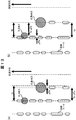
- FIG. 11 shows the positional relationship between the optical disc 102 and the laser spot when information is recorded on the recording layer without performing the recording layer SubSpot tracking control.
- FIG. 11A shows an ideal state where the optical disk 102 is not inclined with respect to the objective lens.
- the tracking control is performed by a method referred to as servo layer tracking control in this specification.
- servo layer tracking control in this specification.
- the servo layer laser spot S_LS is generated on the servo layer by the laser beam S_LB irradiated to the servo layer, and tracking control is performed using this.
- the recording layer laser spot R_LS is generated in the recording layer by the laser beam R_LB irradiated to the recording layer, and information is recorded using this.
- the servo layer laser spot S_LS and the recording layer laser spot R_LS are located on an axis perpendicular to the disk.
- FIG. 11B shows a state where the optical disc 102 is tilted with respect to the objective lens
- A shows the position of the recording layer laser spot R_LS when the optical disc 102 is not tilted with respect to the objective lens.
- the recording layer laser spot R_LS when the optical disk 102 is tilted with respect to the objective lens does not coincide with A.
- Factors that change the relative inclination of the optical disk 102 and the objective lens include a change in warpage of the optical disk itself due to temperature and humidity, and a change in the relative positional relationship between the optical disk device 101 and the optical disk 102 due to chucking.
- the adjacent recording layer track is irradiated with the recording layer sub-spot R_SubLS to perform tracking control, and the recording layer main is located at a position separated by Tp in the radial direction.
- the position of the spot R_MainLS is controlled. Therefore, by using the recording layer SubSpot tracking control, it is possible to solve the problem of overwriting recorded data when the relative inclination of the optical disk 102 and the objective lens changes. That is, by using the recording layer SubSpot tracking control, additional information can be recorded on the grooveless disc.
- the recording layer SubSpot tracking control is a control method that can realize additional recording of information on the grooveless disc.
- another problem exists in realizing the recording layer SubSpot tracking control. Next, this problem will be described.
- FIG. 12 is a schematic diagram showing a laser spot on the recording layer when the recording layer SubSpot tracking control is performed.
- the dotted line indicates the position of the track formed in the recording layer, and the recording layer sub-spot R_SubLS exists at a position separated from the recording layer main spot R_MainLS by the track pitch Tp of the servo layer in the radial direction.
- the distance between the center of the recording layer main spot R_MainLS and the center of the recording layer sub-spot R_SubLS is d, and the angle between the line segment connecting the center of the recording layer main spot R_MainLS and the center of the recording layer sub-spot R_SubLS and the tangential direction is ⁇ . Show.
- the distance d and the angle ⁇ vary due to reasons such as component manufacturing variations and assembly variations. When the variation occurs, the track pitch of the recording layer track formed in the recording layer deviates from Tp which is the design center.
- the track pitch of the recording layer track deviates from Tp, an error occurs in the calculation when seeking, and seek performance deteriorates. Further, when the track pitch is reduced, the reproduction performance is deteriorated due to the influence of adjacent marks. Further, when the track pitch of the recording layer track changes, the recording capacity per layer also changes, and the data capacity of the optical disc 102 cannot be defined.
- a problem in performing the recording layer SubSpot tracking control is that the track pitch of the recording layer track formed on the recording layer is deviated from Tp due to manufacturing variations or assembly variations of parts.
- FIG. 13 is a schematic diagram showing a laser spot on the recording layer when the recording layer SubSpot tracking control is performed.
- This shows a case where the track pitch of the recording layer track formed on the recording layer is deviated from Tp due to parts manufacturing variation or assembly variation, and shows a case where the track pitch is shortened by ⁇ Tp. ing. It is assumed that information is recorded from the inner periphery toward the outer periphery. That is, the left direction in the figure corresponds to the inner circumferential direction.
- FIG. 13A shows a case where the recording layer SubSpot tracking control is performed without using this embodiment, and the track pitch of the recording layer track is Tp ⁇ Tp.
- the control position of the recording layer sub-spot R_SubLS is changed. That is, the recording layer sub-spot R_SubLS is not controlled to follow the adjacent track, but is controlled to a position on the outer peripheral side by ⁇ Tp from the adjacent track. Thereby, the track pitch of the recording layer track becomes Tp.
- Such a change in the control position can be realized by applying an offset to the tracking error signal.
- the recording layer track pitch adjustment voltage generation circuit 1514 functions as an offset output unit.
- the voltage V_TpAdj output from the recording layer track pitch adjustment voltage generation circuit 1514 corresponds to the offset.
- the track pitch is shifted from the state as shown in FIG. 13A to the state shown in FIG. 13B where the track pitch of the recording layer track becomes Tp.
- the value of the R_MainTE signal when the voltage V_TpAdj is changed is monitored. This meaning will be described with reference to FIGS.
- FIG. 14 is a schematic diagram showing a laser spot on the recording layer when the voltage V_TpAdj is changed.
- FIG. 14A shows the initial state, and the state where the track pitch of the recording layer track is Tp ⁇ Tp is the initial state as in FIG.
- FIG. 14B shows a state in which the voltage V_TpAdj is an optimal value and the track pitch is Tp.
- the optimum value of the optimum V_TpAdj is V_BestTpAdj.
- FIG. 14C shows a case where the value of the voltage V_TpAdj is 2 ⁇ V_BestTpAdj.
- FIG. 14C shows a state in which the recording layer sub-spot R_SubLS has moved by 2 ⁇ ⁇ Tp from the initial state of FIG. Therefore, in the comparison with the optimum state in FIG. 14B, the recording layer sub-spot R_SubLS has a relationship of moving by ⁇ Tp to the outer peripheral side.
- (a) and (c) are in a symmetrical relationship with the optimum state (b) as the center.
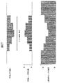
- FIG. 15 shows the waveform of the R_MainTE signal when the recording layer main spot R_MainLS crosses the track.
- (A), (b), and (c) in FIG. 15 correspond to (a), (b), and (c) in FIG. 14, respectively.
- the R_MainTE signal is generated by the DPD (Differential Phase. Detection) method
- the R_MainTE signal becomes a triangular wave as shown in FIG.
- a region A having a positive slope is called a negative period region, and this range is a range in which tracking control can be controlled.
- a region where the slope indicated by B is negative is a region where tracking control cannot be performed.
- the R_MainTE signal takes the value of the reference potential Vref. Therefore, in FIG. 15B, the R_MainTE signal is Vref. Further, (a) and (c) have a symmetrical relationship with the optimum state (b) as the center as shown in FIG. This is because the R_MainTE signal is a signal indicating the radial distance between the recording layer main spot R_MainLS and the adjacent track.
- FIG. 16 shows a signal for each part during the track pitch adjustment of this embodiment and a method for calculating the optimum value of the voltage V_TpAdj.
- FIG. 16A shows the value of the voltage V_TpAdj during the track pitch adjustment of this embodiment
- FIG. 16B shows the R_MainTE signal monitored by the recording layer MainTE signal monitor circuit 1523 at that time. (DC level).
- M_TE the value of the R_MainTE signal monitored by the recording layer MainTE signal monitor circuit 1523
- V_TpAdj the value of V_TpAdj for the i-th time
- M_TE [i] the value of the R_MainTE signal monitored for the i-th time
- the change amount of the voltage V_TpAdj that is changed in step S712 is a fixed value
- the voltage V_TpAdj changes stepwise in the vertical axis direction at equal intervals.
- changing the voltage V_TpAdj output from the recording layer track pitch adjustment voltage generation circuit 1514 at equal intervals is equivalent to moving the recording layer sub-spot R_SubLS at equal intervals in the radial direction. To do.
- the DC level of the R_MainTE signal is a signal indicating the radial distance between the recording layer main spot R_MainLS and the adjacent track
- the voltage V_TpAdj changes stepwise as shown in FIG. 16A
- the R_MainTE signal The DC level also changes stepwise as shown in FIG.
- V_TpAdj [i] and M_TE [i] obtained in this way are plotted on a graph of V_TpAdj and M_TE as shown in FIG. 16C, each data is arranged in a straight line.
- the optimum value of the voltage V_TpAdj to be finally obtained in the track pitch adjustment is the value of the voltage V_TpAdj that causes the recording layer main spot R_MainLS to overlap the adjacent track.
- the value of the voltage V_TpAdj is obtained so that the DC level of the R_MainTE signal monitored by the recording layer MainTE signal monitor circuit 1523 becomes the reference potential Vref.
- step S716 the optimum value calculated in step S715 is set, and the state is continued thereafter.
- the problem in performing the recording layer SubSpot tracking control is that the distance in the radial direction between the recording layer main spot R_MainLE and the recording layer sub-spot R_SubLS is the track pitch Tp of the servo layer as shown in FIGS. It was to deviate from.
- the control position of the recording layer sub-spot R_SubLS can be changed to the optimum position so that the state shown in FIG.
- the track pitch of the recording layer track can be set to Tp.
- the effect of this embodiment is that the radial distance between the recording layer main spot R_MainLE and the recording layer sub-spot R_SubLS deviates from the track pitch Tp of the servo layer for reasons such as manufacturing variations and assembly variations of parts.
- the track pitch of the recording layer track can be set to Tp. Thereby, deterioration of seek performance and reproduction performance can be suppressed.
- step S718 in which information is recorded by the recording layer sub-spot tracking control the optimum V_TpAdj has already been set.
- the track pitch adjustment is performed before the information is recorded by the recording layer sub-spot tracking control.
- the track pitch adjustment is an adjustment necessary for recording information by the recording layer sub-spot tracking control, it is obvious that this order is necessary.
- an operation of performing one track jump in synchronization with the rotation is performed.
- the track pitch adjustment monitors the R_MainTE signal, it is desirable to monitor one rotation of the disk and use the average value (ie, DC level). From the above, in order to adjust the track pitch while performing one track jump in synchronization with the rotation, it is necessary to adjust the track pitch in the recorded area of two or more tracks. Therefore, in the initial recording in step S705, it is necessary to perform recording for two or more rotations of the disc.
- FIG. 15 shows the waveform of the R_MainTE signal when the recording layer main spot R_MainLS crosses the track, but the R_SubTE signal has the same waveform.
- the controllable range of the tracking control is the negative feedback region indicated by A in FIG. 15. Therefore, the value of the voltage V_TpAdj to be changed by the track pitch adjustment is such that the detrack amount related to the R_SubTE signal is within the negative feedback region. It is necessary to set within the range that does not appear. In the case of FIG. 15, this corresponds to setting the absolute value of the voltage V_TpAdj within a range that does not exceed the absolute value of the R_SubTE signal at both ends of the region A.
- the value of the voltage V_TpAdj is adjusted so that the DC level of the R_MainTE signal monitored by the recording layer MainTE signal monitor circuit 1523 becomes the reference potential Vref.
- the optical disc apparatus 101 may be provided with a circuit for removing the offset.
- the adjustment target potential of the R_MainTE signal deviates from the reference potential Vref of the signal processing circuit 105 by the amount of offset to be removed. Therefore, more precisely, it is more accurate to express that the DC level of the R_MainTE signal monitored by the recording layer MainTE signal monitor circuit 1523 is adjusted to a predetermined value.
- the predetermined value is equal to the reference potential Vref.
- the recording layer main spot R_MainLS and the R_MainTE signal which is a signal indicating the radial distance between adjacent tracks, are monitored to adjust the track pitch.
- another signal may be used as the signal monitored by the track pitch adjustment as long as the signal exhibits a behavior corresponding to the radial distance between the recording layer main spot R_MainLS and the adjacent track.
- a reproduction signal can be used as such a signal.
- the optical disc apparatus 101 may be provided with a circuit for monitoring the amplitude of the reproduction signal obtained by R_MainLS, and the track pitch adjustment for obtaining the value of the voltage V_TpAdj that maximizes the amplitude may be performed.
- the R_MainTE signal and the reproduction signal obtained by R_MainLS have been described as examples of signals to be monitored when track pitch adjustment is performed. These are common in that they are generated from a detector 1314 that detects the intensity of light reflected at the recording layer main spot R_MainLS. That is, the output of the detector 1314 may be used as a signal for confirming whether or not the recording layer main spot R_MainLS is irradiated on the adjacent track. Further, it is obvious that signals other than the above two may be monitored as long as the signals are generated from the detector 1314.
- the problem in the case of performing the recording layer SubSpot tracking control can be solved, and the recording layer SubSpot tracking control can be appropriately performed.
- the track pitch of the recording layer track can be made to coincide with the track pitch Tp of the servo layer with high accuracy, and good seek performance and good reproduction performance can be achieved. Furthermore, the data capacity of the optical disk 102 can be defined reliably.
- the track pitch adjustment is performed using the recording unit of the optical disc 102 inserted in the optical disc apparatus 101 in the recording process when the host 114 is instructed to record information. This is for solving the problem that the track pitch of the recording layer track deviates from Tp, and there are two causes for this problem in this specification. One is the manufacturing variation or assembly variation of the parts, and the other is the warp of the optical disc itself or the inclination when the optical disc 102 is mounted.
- the recording layer track pitch deviation is a value specific to the pickup.
- the present embodiment is an embodiment paying attention to this.
- FIG. 1 is a block diagram of the first embodiment.
- the configuration of the servo error signal generation circuit 104 and the configuration of the signal processing circuit 105 are also the same as those in FIGS. 2 and 3 which are the configuration diagrams of the first embodiment.
- FIG. 17 shows a flowchart of the recording process of this embodiment when the host 114 is instructed to record information.
- the optical disc apparatus 101 When the recording of information is instructed from the host 114, the optical disc apparatus 101 starts the recording process (step S1701). In the recording process, the optical disk apparatus 101 first confirms whether or not the recording by this recording process is the first recording for the currently inserted optical disk (step S1702).
- the optical disc apparatus 101 starts the objective lens drive servo layer tracking control (step S1703).
- the optical disc apparatus 101 issues a command to the slider control circuit 1521 from the system control circuit 1501, and drives the slider motor 112 so that the optical pickup 103 comes to a predetermined radius (step S1704).
- the predetermined radius is assumed to be the innermost radius of the optical disc 102.
- the optical disc apparatus 101 records a part of information instructed to be recorded by the host 114. At this time, recording is performed for one or more rotations of the disc (step S1705). This operation is hereinafter referred to as initial recording.
- the optical disc apparatus 101 After recording information of one or more revolutions of the disc in step S1705, the optical disc apparatus 101 stops the initial recording (step S1706).
- step S1706 the optical disc apparatus 101 ends the objective lens drive servo layer tracking control (step S1707).
- the optical disk apparatus 101 instructs the recording layer track pitch adjustment voltage generation circuit 1514 to output the R_TpAdj signal.
- the voltage V_TpAdj is changed to a predetermined value (step S1708).
- a predetermined value a value stored in a non-volatile memory (not shown) provided in the system control circuit 1501 is used.
- step S1716 the optical disc apparatus 101 starts recording layer SubSpot tracking control (step S1709), and then starts relay lens drive servo layer tracking control (step S1710).
- step S1717 After starting the relay lens drive servo layer tracking control in step S1717, information is recorded, and all information instructed to be recorded by the host 114 is recorded (step S1711). If the initial recording in step S1705 has been performed, the recording of information is resumed from the recorded continuation. When the information recording is finished in step S1711, the recording process is finished (step S1712).
- the present embodiment assumes a case in which the problem that the track pitch of the recording layer track deviates from Tp is caused by the manufacturing variation and assembly variation of components.
- the component variation and the assembly variation referred to here are related to the components constituting the pickup 103, and are values specific to the pickup 103. Therefore, it is not necessary to adjust the track pitch every time the recording operation is performed as in the first embodiment, and a value unique to the apparatus may be set before recording information by the recording layer sub-spot tracking control.
- the distance between the two laser spots R_MainLS and R_SubLS generated on the recording layer at the time of manufacturing the optical disc apparatus 101 is investigated, and the investigation result is provided in the system control circuit 1501.
- Store in non-volatile memory Before the information is recorded by the recording layer sub-spot tracking control, the value is read and the voltage V_TpAdj of the recording layer track pitch adjustment voltage generation circuit 1514 is set to an optimum value.
- the same effect as in the first embodiment can be achieved. That is, even when the radial distance between the recording layer main spot R_MainLE and the recording layer sub-spot R_SubLS deviates from the track pitch Tp of the servo layer as shown in FIGS. 14A and 14C.
- the control position of the recording layer sub-spot R_SubLS can be changed to the optimum position, and the state shown in FIG. 14B can be obtained.
- the problem in the case of performing the recording layer SubSpot tracking control can be solved, and the recording layer SubSpot tracking control can be appropriately performed.
- the track pitch of the recording layer track can be made to coincide with the track pitch Tp of the servo layer with high accuracy, and good seek performance and good reproduction performance can be achieved. Furthermore, the data capacity of the optical disk 102 can be defined reliably.
- the structure of the optical disc 102 is such that the recording surface coated with the recording film is laminated in the film thickness direction.
- the application range of the present invention is not limited to the optical disk having the structure shown in FIG. Any optical disc having a recording layer capable of generating a focus error signal can be applied.
- the recording layer focus error may occur even in an optical disc in which information is recorded or reproduced by irradiating a uniform medium with a laser beam having a wavelength of 405 nm.
- a signal can be generated, focus control can be performed on the information recording surface, and the present invention can be applied to tracking control within the surface.
- a uniform medium has a structure for specifying the recording position of information in the recording medium, and a recording layer focus error signal is generated from the output signal of the detector by the structure, so that the information is obtained in a planar shape.
- the present invention can be similarly applied to an optical disc in which recording is performed to form a recording layer.
- the optical disk 102 has a structure having a servo layer, but the present invention can also be applied to an optical disk having no servo layer.
- the present invention when two laser spots are arranged in the recording layer and tracking is performed with one laser spot and recording light emission is performed with the other laser spot, the track pitch formed in the recording layer is the design target value (above).
- the problem of deviating from Tp) is solved. Therefore, the present invention can be similarly applied to an optical disc having no servo layer in that the radial distance between mark rows formed on the recording layer is adjusted.
- the first recording is performed only when the first recording is instructed for the currently inserted optical disk. Therefore, even when there are a plurality of recording layers, initial recording was performed on one of the layers to create a recording portion, and the track pitch was adjusted in the recording portion.
- the other recording layers were operated using the values obtained by adjusting the track pitch in the above layers.
- the recording portion may be created in each layer and the track pitch may be adjusted. As a result, even when the interlayer thickness is not uniform and the recording layer is inclined in some recording layers, the track pitch of the recording layer track can be adjusted more accurately to be the same as the servo layer track pitch. it can.
- the half-pitch position where the first recording is performed is the innermost circumference of the optical disc 102.
- the radial position where the initial recording is performed may be any radial position on the optical disc 102.
- the track pitch adjustment is performed at the radial position where the initial recording is performed.
- the track pitch may be adjusted using any of the recording portions.
- the initial recording in the above embodiment is an operation performed after the host 114 is instructed to record information, it may be performed before that. For example, you may perform by a setup process.
- the track pitch adjustment is performed at a plurality of radial positions, and the value of the voltage V_TpAdj output from the recording layer track pitch adjustment voltage generation circuit 1514 is changed according to the radial position, thereby changing the inclination of the optical disk 102 depending on the radius Even so, it can be operated so that the track pitch of the recording layer track is the same as the servo layer track pitch.
- the method for determining the voltage V_TpAdj according to the radial position the track pitch is adjusted at the innermost circumference and the outermost circumference. There is a method of linear interpolation.
- the radial distance between the two laser spots R_MainLS and R_SubLS generated on the recording layer is arranged so as to be substantially equal to the track pitch Tp of the servo layer.
- the distance may be other than Tp.
- it may be an integral multiple of the track pitch Tp.
- the recording layer sub-spot R_SubLS is irradiated onto the recording layer track that is two tracks away from the recording track, thereby recording at a position on the outer circumference side by twice Tp.
- the position of the layer main spot R_MainLS is controlled and information is recorded. Also in this case, since overwriting of recorded data can be prevented when the relative inclination of the optical disc 102 and the objective lens changes, the advantage of the recording layer SubSpot tracking control is maintained also in that case.
- the radial distance between the two laser spots R_MainLS and R_SubLS generated on the recording layer may be half of the track pitch Tp of the servo layer.
- the case where the track pitch is half of the track pitch Tp is a case where the servo layer has a CAPA (Complementary Allocated Pit Address) structure such as a DVD-RAM as described in Patent Document 2.
- CAPA Common Allocated Pit Address
- the distance between the mark rows in the radial direction is half the track pitch.
- the track pitch of the recording layer track is half of Tp, but the distance in the radial direction of the laser spots R_MainLS and R_SubLS is the same as the track pitch of the recording layer track. Since the track pitch adjustment is an adjustment related to the recording layer, it is the same as in the first embodiment that the track pitch must be adjusted in an area where two or more tracks are recorded in the recording layer. That is, in the initial recording when the radial distance between the laser spots R_MainLS and R_SubLS is half the track pitch Tp of the servo layer, it is necessary to perform recording for two or more rotations of the disk.
- the R_SubTE signal is generated by the DPD method.
- the present invention can be similarly applied when other generation methods are used.
- the DPP method is known as a method for generating different tracking error signals, and in this case as well, it can be similarly applied, including the discussion regarding the negative feedback region described above.
- the optical disc apparatus 101 includes the recording layer track pitch adjustment voltage generation circuit 1514, and the track pitch adjustment is performed by adjusting the voltage V_TpAdj output from the recording layer track pitch adjustment voltage generation circuit 1514.
- the present invention finds that the track pitch of the recording layer track formed in the recording layer deviates from Tp when performing the recording layer SubSpot tracking control, and is an invention for the problem. Therefore, the method of adjusting the track pitch may be other than the method of adjusting the voltage V_TpAdj output from the recording layer track pitch adjustment voltage generation circuit 1514.
- the optical pickup 103 includes an optical element capable of adjusting a radial distance between two laser spots R_MainLS and R_SubLS generated on the recording layer, and the optical element 103 is used to adjust the radial distance between the two laser spots. The distance may be adjusted.
- the offset is applied to the tracking error signal, and the voltage V_TpAdj output from the recording layer track pitch adjustment voltage generation circuit 1514 is added to the voltage of the tracking error signal by the adder 1515.
- offset addition may take a form other than voltage addition.
- the signal processing circuit 105 is a digital LSI, it is obvious that application of an offset can be read as addition of a digital value.
- the recording layer tracking error signal R_TE to which the voltage V_TpAdj output from the recording layer track pitch adjustment voltage generation circuit 1514 is added is generated by the servo error signal generation circuit 104 shown in FIG.
- Each error signal generation circuit in the servo error signal generation circuit 104 preferably performs AGC (Auto Gain Control) based on the total light amount.
- the recording layer sub-tracking error signal generation circuit 1401 performs normalization based on the AGC based on the total light amount, that is, the total electric signal received by the detector 1324, so that, for example, the reflected light amount changes depending on the recording state of the front recording layer. Can also remove the effect. Therefore, the value to which the voltage V_TpAdj output from the recording layer track pitch adjustment voltage generation circuit 1514 is added can be constant regardless of the recording state of the previous recording layer.
- the voltage V_TpAdj output from the recording layer track pitch adjustment voltage generation circuit 1514 is added as the R_TE signal that is the input signal of the recording layer tracking control circuit 1516, but the position where the voltage V_TpAdj is added is It may be a signal inside the recording layer tracking control circuit 1516.
- the same laser power control circuit 1301 is used to drive the laser diode 1302 and the laser diode 1315.
- each laser diode may be provided with a laser power control circuit unique to each laser diode.
- the spherical aberration correction element 1309 may be disposed at a position that affects both the 405 nm optical system and the 650 nm optical system.
- the spherical aberration correction element 1309 may be disposed between the quarter wavelength plate 1310 and the dichroic mirror 1308. .
- FIG. 20 shows the structure (cross section) of an optical disc 222 targeted by this embodiment.
- the optical disk 222 shown in the figure is an optical disk 222 having one guide layer with grooves and one or more flat recording layers without grooves.
- the groove of the guide layer is a spiral groove centered on the disk rotation axis, like the groove found on a disk such as DVD or BD.
- the groove has a undulation structure (wobble) having a substantially constant period in the length direction as seen in a disk such as a DVD or a BD.
- information indicating the current position (address) is added to the guide layer so as to be seen on a disc such as a DVD or a BD.
- a method of adding an address includes adding a portion to be modulated to wobble and adding a pit to the groove structure.
- the objective lens 311 in the figure is an objective lens 311 of an optical disc recording / reproducing apparatus (not shown) for condensing a laser beam on the optical disc 222.
- two different light beams pass through the objective lens 311, one light beam generates a laser spot LSg on the guide layer of the optical disk 222, and the other light beam is out of a plurality of recording layers of the optical disk 222.
- the laser spot LSW is generated.
- the optical disk 222 targeted by this embodiment performs recording or reproduction using two or two or more light beams.
- FIG. 19 is a block diagram showing an embodiment of the optical disc recording / reproducing apparatus 221 according to the present invention.
- the optical disk recording / reproducing apparatus 221 records or reproduces information by irradiating an optical disk 222 mounted on the apparatus with laser light, and communicates with a host 223 such as a PC (Personal Computer) through an interface such as SATA (Serial Advanced Technology Attachment). Communicate.
- a host 223 such as a PC (Personal Computer) through an interface such as SATA (Serial Advanced Technology Attachment). Communicate.
- the optical disc recording / reproducing apparatus 221 includes a controller 201, a signal processing unit 202, an optical pickup 203, a slider motor 204 that moves the optical pickup 203 in the radial direction of the optical disc 222, a slider driving unit 205 that drives the slider motor 204, Aberration correction driving means 206 for driving the spherical aberration correction element 309 provided in the optical pickup 203, a spindle motor 207 for rotating the optical disk 222, and a rotation signal for rotating the spindle motor 207 are generated.
- the optical pickup 203 performs servo control on the guide layer, and data on a guide layer optical system for reproducing an address and disc-specific information corresponding to the position on the disc, and a plurality of recording layers at different distances from the guide layer. Is composed of a recording layer optical system for recording / reproducing data.
- the laser driver 301 is controlled by the controller 201 and outputs a current for driving the laser diode 302.
- This drive current is applied with high frequency superposition of several hundred MHz in order to suppress laser noise.
- the laser diode 302 emits a laser beam LBw having a wavelength of 405 nm, for example, with a waveform corresponding to the drive current.
- the emitted laser light becomes parallel light by the collimator lens 303, a part of the light is reflected by the beam splitter 304, and is condensed on the power monitor 306 by the condenser lens 305.
- the power monitor 306 feeds back a current or voltage corresponding to the intensity of the laser light to the controller 201.
- the intensity of the laser beam LBw focused on the recording layer of the optical disc 222 is maintained at a desired value such as 2 mW.
- the laser beam LBw that has passed through the beam splitter 304 is reflected by the polarization beam splitter 307, and the convergence / divergence is controlled by the spherical aberration correction element 309 driven by the aberration correction drive means 206, and passes through the dichroic mirror 308.
- the dichroic mirror 308 is an optical element that reflects light of a specific wavelength and transmits light of other wavelengths. Here, it is assumed that light having a wavelength of 405 nm is transmitted and light having a wavelength of 650 nm is reflected.
- the laser beam LBw that has passed through the dichroic mirror 308 becomes circularly polarized light by the quarter-wave plate 310 and is condensed as a laser spot LSW on the recording layer of the optical disc 222 by the objective lens 311.
- the spherical aberration correction element 309 is controlled from the controller 201 via the aberration correction driving means 206 so as to be at a predetermined position corresponding to the recording layer of the grooveless disk.
- the intensity of the laser beam LBw reflected by the optical disc 222 is modulated in accordance with information recorded on the optical disc 222.
- the light is linearly polarized by the quarter-wave plate 310, passes through the dichroic mirror 308, and passes through the polarization beam splitter 307 and the spherical aberration correction element 309.
- the transmitted laser light LSW is condensed on the detector 314 by the condenser lens 313.
- the detector 314 detects the intensity of the laser beam LBw and outputs a signal corresponding to the intensity to the signal processing means 202.
- the focus error signal generation unit 211 generates a recording layer focus error signal for the recording layer from the signal output from the detector 314.
- the focus control unit 212 outputs a focus drive signal corresponding to the focus error signal to the focus drive unit 213 in response to a command signal from the controller 201.
- the focus drive unit 213 drives the actuator 312 according to the focus drive signal to displace the position of the objective lens 311 in the direction perpendicular to the recording surface, and the recording layer focus servo so that the laser beam LBw is focused on the recording layer. Take control.
- the signal output from the detector 314 is also input to the tracking error signal generation unit 214 to generate a recording layer tracking error signal for the recording layer.
- FIG. 28 shows an internal configuration of the tracking error signal generation unit 214.
- the tracking error signal generation unit 214 performs tracking using the light spot 501 and the SUB tracking error signal generation unit 1101 that generates the tracking error signal from the light spot 502 and the main tracking error signal generation unit 1102 that generates the tracking error signal from the light spot 500.
- a SUB tracking error signal generating unit 1103 and a tracking error signal selecting unit 1104 for selecting a tracking error signal to be output depending on a state such as recording, reproduction, and OPC are provided.
- the tracking error signal selection unit 1104 outputs, for example, the tracking error signal generated by the Main tracking error signal generation unit 1102 when reproducing information, and the tracking error generated by the subsequent Sub tracking error signal generation unit 1103 during recording. It operates by switching the tracking error signal to be output as described later during OPC.
- the tracking error signal generating means there are three light spots 500 to 502 focused on the recording layer.
- the tracking error signal generating means 214 can output the tracking error signal.
- the tracking control unit 215 outputs a tracking drive signal corresponding to the output of the tracking error signal generation unit 214 or the tracking error signal generation unit 210 to the tracking drive unit 216 according to a control signal from the controller 201.
- the laser driver 301 is controlled by the controller 201 and outputs a current for driving the laser diode 315.
- the laser diode 315 emits laser light LBg having a wavelength of 650 nm, for example.
- a part of the laser beam LBg is monitored by a power monitor 319 through a collimator lens 316, a beam splitter 317, and a condenser lens 318.
- the intensity of the laser beam LBg focused on the guide layer of the optical disc 222 is maintained at a desired power such as 3 mW.
- the laser beam LBg that has passed through the beam splitter 317 passes through the polarization beam splitter 320 and is controlled by the relay lens 321 to converge, diverge, and change the optical axis.
- the laser beam LBg that has passed through the relay lens 321 is reflected by the dichroic mirror 308, passes through the quarter-wave plate 310, and is condensed as a laser spot LSg on the guide layer of the optical disc 222 by the objective lens 311.
- the laser beam LBg reflected by the optical disk 222 is reflected by the polarization beam splitter 320 and condensed on the detector 323 by the condenser lens 322.
- the Detector 323 detects the intensity of the laser beam and outputs a signal corresponding to this to signal processing means 202.
- the signal processing means 202 is a synchronization signal for controlling the rotation of the optical disc 222 by a signal corresponding to a track formed by wobbling the guide layer output from the detector 323, and a clock used as a reference for recording or reproduction A signal is generated, and an address corresponding to the position on the optical disc 222 that the laser spot LSg follows is reproduced and output to the controller 201.
- the synchronization signal output from the signal processing unit 202 and the FG signal output from the spindle driving unit 209 are input to the spindle control unit 208.
- the spindle control means 208 outputs a spindle drive signal based on an FG signal having a frequency corresponding to the rotational speed of the spindle motor 207 when the optical disk 222 is rotated at a constant angular velocity by the control signal from the controller 201, and the optical disk 222 is When rotating at a constant linear velocity, a spindle drive signal based on the synchronization signal reproduced from the guide layer is output.
- the spindle driving means 209 performs spindle control so that the rotational speed of the optical disc 222 becomes a predetermined value by driving the spindle motor 207 in accordance with the spindle driving signal.
- the focus error signal generation unit 217 generates a guide layer focus error signal corresponding to the deviation between the guide layer of the optical disc 222 and the in-focus position of the laser spot LSg from the signal output from the detector 323, and the relay lens control unit 218 A relay lens driving signal corresponding to the layer focus error signal is generated.
- the relay lens driving means 219 performs guide layer focus servo control so that the laser spot LSg is focused on the guide layer by driving the relay lens 321 according to the relay lens drive signal.
- the relay lens driving means 219 changes the relative position in the radial direction between the laser spot LSg and the laser spot LSw by driving the relay lens 321 to change the optical axis according to the tracking drive signal.
- the tracking error signal generation unit 210 generates a guide layer tracking error signal corresponding to the positional deviation between the track of the guide layer of the optical disc 222 and the laser spot LSg from the signal output from the detector 323, and the tracking control unit 215 Output to.
- the tracking control unit 215 outputs a tracking drive signal corresponding to the output of the tracking error signal generation unit 214 or the tracking error signal generation unit 210 to the tracking drive unit 216 according to a control signal from the controller 201.
- the laser spot LSW is recorded on the recording layer by driving the actuator 312 with the focus drive signal generated based on the recording layer focus error signal output from the focus error signal generating unit 211.
- the recording layer focus servo control is performed so as to focus on the layer, and the relay lens 321 is driven by the relay lens drive signal generated based on the guide layer focus error signal output from the focus error signal generation unit 217.
- Guide layer focus servo control is performed so that the laser spot LSg is focused on the guide layer in the recording layer.
- the tracking drive signal generated based on the tracking error signal output from the tracking error signal generating unit 214 or the tracking error signal generating unit 210 from the tracking control unit 215 by the control signal from the controller 201 is sent to the tracking driving unit 216. Is output.
- the tracking drive means 216 drives the actuator 312 and the relay lens 321 according to the tracking drive signal, so that the laser spot LSg follows the track of the guide layer, and the light spot 501 or the light spot 502 that does not perform recording is recorded on the recording layer. Tracking servo control is performed so as to follow the mark row.
- the slider control means 220 that receives the control signal from the controller 201 outputs a slider drive signal for driving the slider motor 204 based on the average value of the tracking drive signal.
- the slider motor 204 is driven by the slider drive means 205, and the optical pickup 203 is moved in the disk radial direction so that the actuator 312 operates in the vicinity of the center position of the movable range in the disk radial direction.
- Data to be recorded on the recording layer input from the host 223 and address information corresponding to the position on the optical disc 222 where the data is recorded are output from the controller 201 to the signal processing means 202.
- the signal processing means 202 modulates the input data and address information by a predetermined method based on the reference clock signal reproduced from the guide layer, and outputs it to the laser driver 301.
- the laser driver 301 outputs a drive current corresponding to the output of the signal processing means 202 to the laser diode 302, and the laser diode 302 emits the laser beam LBw with a corresponding intensity, so that recording is performed on the recording layer of the optical disc 222.
- recording can be performed on the recording layer at the focal distance between the light spot 500 for recording and the light spot 501 or the light spot 502 for servo control.
- the light spot 500 and the light spot 501 or servo spot 502 for which servo control is performed at the same focal distance as the track spacing of the guide layer information is recorded on the recording layer in the same locus as the spiral of the guide layer track. Can be done.
- the guide layer track is changed from the outer periphery to the inner periphery.
- a recording mark can be formed in a spiral shape from the outer periphery to the inner periphery.
- the actuator 312 When reproducing the information recorded on the recording layer, the actuator 312 is driven by the focus drive signal generated based on the recording layer focus error signal output from the focus error signal generating means 211, thereby causing the recording layer to laser. Recording layer focus servo control is performed so that the spot LSW is focused on the recording layer. Further, by driving the relay lens 321 with the relay lens driving signal generated based on the guide layer focus error signal output from the focus error signal generating means 217, the laser spot LSg is focused on the guide layer at the guide layer. The guide layer focus servo control is performed.
- the tracking error detection unit 214 outputs a tracking error signal corresponding to the deviation between the track formed by the locus of information recorded on the recording layer and the light spot 500 irradiated on the recording layer.
- a tracking drive signal generated based on the recording layer tracking error signal output from the tracking error signal generation unit 214 is output from the tracking control unit 215 to the tracking drive unit 216 by the control signal from the controller 201.
- the tracking drive means 216 drives the actuator 312 according to the tracking drive signal, and tracking servo control is performed so that the light spot 500 follows the track formed by the locus of information recorded on the recording layer, and recording is performed from the detector 314.
- a reproduction signal from the layer is output.
- the slider control means 220 that receives the control signal from the controller 201 outputs a slider drive signal for driving the slider motor 204 based on the average value of the tracking drive signal.
- the slider motor 204 is driven by the slider drive means 205, and the optical pickup 203 is moved in the disk radial direction so that the actuator 312 operates in the vicinity of the center position of the movable range in the disk radial direction.
- the signal processing means 202 generates a synchronization signal for controlling the rotation of the optical disc 222 and a clock signal serving as a reference for reproduction from the input reproduction signal.
- the signal processing unit 202 performs processing such as amplification, equalization, and decoding on the reproduction signal, and outputs the decoded data and address information corresponding to the position of the data on the optical disk 222 to the controller 201.
- the controller 201 outputs the reproduced data to the host 223.
- each laser diode may be provided with a laser driver specific to it.
- the spherical aberration correction element 309 may be disposed at a position that affects both the 405 nm optical system and the 650 nm optical system, and may be disposed between the quarter wavelength plate 310 and the dichroic mirror 308, for example. .
- FIG. 21 shows a processing flow of the optical disc recording / reproducing apparatus 221 when the optical disc 222 is inserted into the optical disc recording / reproducing apparatus 221.
- the optical disc recording / playback device 221 checks the presence / absence of a disc and the disc type in S402. At this time, for example, the optical disc recording / reproducing apparatus 221 can irradiate the optical disc 222 with laser light and perform recognition by reflected light.
- adjustment processing for making various parameters in the optical disc recording / reproducing apparatus 221 suitable is performed on the inserted optical disc 222.
- the various parameters include adjusting the amplification factor of the amplifier included in the focus control unit 212 and the tracking control unit 215 in accordance with the reflectance of the optical disc 222.
- the management information of the optical disc 222 is read in S404.
- the timing of the adjustment process S403 is not limited to this, and part of the adjustment process may be performed after the management information read S404.
- FIG. 29 shows a processing flow in the case where a recording command is sent to the optical disc recording / reproducing apparatus 221 in a state where recording or reproduction is possible.
- the optical disc recording / reproducing apparatus 221 determines whether or not the OPC process is necessary when recording on the optical disc 222 currently inserted (S1202).
- the OPC processing is necessary when, for example, the optical disc 222 is inserted into the optical disc recording / reproducing apparatus 221 and the optimum laser beam intensity for recording is not obtained for the inserted optical disc 222, such as when the first recording command is received. It is determined. If it is determined that the OPC process is necessary, an OPC process to be described later is performed to obtain an optimum recording laser beam intensity (S1203). Thereafter, a seek operation is performed to position the laser spot LSW and the laser spot LSg at the recording position (S1204). Thereafter, a recording process (S1205) is performed.
- the recording process (S1204) will be described with reference to FIG.
- FIG. 22 is an enlarged view of a part of the optical disk 222 having the structure shown in FIG.
- FIG. 22 shows a state in which a recording light spot 500 is focused on the recording layer and a mark is recorded while proceeding in the tangential direction of the optical disk 222.
- the tracking servo control light spot 501 and the light are recorded.
- a spot 502 is placed at a certain distance in the radial direction from the light spot 500 and the optical disc 222, and is focused on the recorded mark and on the area where the mark is to be recorded (unrecorded area). It shows that the light spot 511 is condensed in the groove (track) of the guide layer substantially directly below the light spot 500.
- the light spots 500, 501, and 502 are originally separated from the same light flux and emitted from the same objective lens 311 (not shown), and are described as laser spots LSW in FIG.
- the light spot 511 is a light flux different from that of the light spots 500, 501, and 502, but indicates that the light spot 511 is emitted from the same objective lens 311, and is described as a laser spot LSg in FIG.
- the optical disc recording / reproducing device 221 controls tracking so that the light spot 501 or the light spot 502 follows the recorded mark when a recorded mark exists in the recording layer, and determines the position of the light spot 500 in the disc radial direction. Then, the mark is recorded by changing the intensity of the laser beam of the light spot 500.
- the light spot 511 is controlled so as to be positioned on the track of the guide layer, and by reading the wobble of the track, the relative speed between the light spot 500 and the optical disk 222 is obtained, thereby determining the length of the mark to be recorded. .
- the recording operation ends (S1206). If it is determined that the OPC process is unnecessary, the seek operation (S1204) and the recording operation (S1295) are performed, and the recording operation ends (S1206).
- FIG. 23 shows an example of a flowchart of the OPC operation.
- the OPC operation is started S1601
- the laser spot LSW may be moved to the OPC region of the designated layer to identify whether the recording mark row is detected from the reflected light. If it is the first OPC for the specified layer, it is positioned at the position of the first OPC (S1603).
- the tracking control unit 215 outputs a signal for driving the tracking driving unit 216 based on the tracking error signal from the tracking error signal generating unit 210, and moves the objective lens 311. At this time, the tracking control unit 215 does not output the driving signal to the relay lens driving unit 219 or outputs a constant signal. Since the input to the relay lens driving means 219 is constant or not input, the radial direction of the relay lens 321 is not driven or is positioned at a fixed position. Thereafter, the first OPC operation S1604 is performed.
- the operation of the OPC is, for example, by performing test recording while changing the intensity of the laser beam, and then reproducing the area where the test recording has been performed, and the optimum recording laser based on the change in the amplitude of the reproduction signal and the intensity of the laser beam at the time of the test recording
- the optimum laser light intensity is obtained by calculating the light intensity.
- a mark row is recorded S1605 in the OPC area with the intensity of the laser beam obtained by the previous OPC.
- the mark row to be recorded has a pattern in which the recording mark row and the unrecorded portion for OPC alternate in one round.
- the tracking control unit 215 outputs a signal for driving the tracking driving unit 216 based on the tracking error signal from the tracking error signal generating unit 210, and moves the objective lens 311. At this time, the tracking control unit 215 does not output the driving signal to the relay lens driving unit 219 or outputs a constant signal. Since the input to the relay lens driving means 219 is constant or not input, the radial direction of the relay lens 321 is not driven or is positioned at a fixed position. The current position at the time of recording is acquired from address information added to the guide layer.
- the pattern method for performing recording with the optimum laser light intensity in the OPC area may be recorded so that tracking servo control can be performed by switching the light spot that generates the tracking error signal, as will be described later.
- the optical disc recording / reproducing apparatus 221 having the light spot 501 and the light spot 502 on one track before and after the light spot 500 to be recorded, at least 3 tracks at any point are extracted from 3 consecutive tracks. If there is a mark row recorded with an optimum laser beam intensity for the track, stable tracking servo control can be performed in the OPC area, and N light beams having different distances from the recording light spot 500 in the radial direction of the optical disk 222. In the case of the optical disk 222 having spots, stable tracking servo control is possible if there is a mark row recorded with an optimum laser beam intensity for at least one continuous N track.
- a rotation synchronization signal from the spindle motor 207 is used to switch a light spot that generates a tracking error signal when recording one mark per track for three tracks. But you can take the timing.
- the circumferential length of an unrecorded track that does not generate a mark row with the optimum laser light intensity to be an integral multiple of the length used in OPC, all areas that cannot be used in test recording for OPC It can be recorded as a record mark row for tracking servo control.
- the light spot that generates the tracking error signal becomes longer since the tracking error signal generated from both the light spot before and after the switching is approximately the same in the vicinity of the switching timing. It is possible to increase the time width during which switching is possible.
- the mark row to be recorded is good because it is possible to detect the position of the light spot 500 that is currently recording / reproducing during tracking servo control of the OPC area by entering layer information and an address indicating the radial position. .
- the current light spot 500 is in focus before track control is performed. It is good because the layer can be detected.
- the recorded mark row is recorded not for recording information at a high density but for generating a tracking error signal that enables stable tracking servo control of the light spot 500, so that actual information is recorded. Unlike the mark row of the portion to be processed, if the mark row has a stable quality of the tracking error signal, stable tracking servo control may be possible.
- the OPC operation ends (S1608). If the OPC for the specified layer of the inserted optical disk 222 is the second or later, the tracking servo is performed using the mark train recorded with the optimum recording laser light intensity already recorded in the OPC area. Control is performed, and an area usable for OPC is searched S1606.
- FIG. 18 is a diagram illustrating three times during which the light spot 500, the light spot 501, and the light spot 502 are performing tracking servo control on the recording mark row in the OPC area. Time advances in the order of (a), (b), and (c), and the light spot 500, the light spot 501, and the light spot 502 advance from left to right as viewed in the figure.
- tracking servo control is performed using the tracking error signal generated from the light spot 500.
- the light spot that generates the tracking error signal is switched from the light spot 500 to the light spot 501 or the light spot 502, and tracking servo control is performed.
- the light spot for generating the tracking error signal is switched from the light spot 501 or the light spot 502 to the light spot 500 to perform tracking servo control.
- the light spot that generates the tracking error signal is switched using the tracking error signal selection means 1104 and tracking servo control is performed, so that the mark row is not recorded or the laser light intensity is optimized. It is possible to scan the light spot 500 while performing stable tracking servo control even on a track where there is a non-existing region.
- the switching operation of the tracking error signal selection means 1104 may be performed based on position information read from a recorded mark row, for example.
- the light spot that generates the tracking error signal may be switched when the signal amplitude from the mark row obtained from the light spot to be switched next becomes a certain value or more.
- switching the light spot that generates the tracking error signal according to the pattern enables switching timing so that the switching timing can be grasped in advance. This is good because the process can be simplified.
- the OPC operation is performed while performing the tracking servo control by performing the switching operation of the light spot that generates the tracking error signal (S1606).
- the OPC operation here is characterized in that the OPC operation is performed by applying tracking servo control to the first OPC operation S1604 while switching the light spot that generates the tracking error signal.
- OPC processing is performed while performing stable tracking servo control by performing tracking servo control with a light spot different from the light spot 500 where recording is actually performed, and performing the second and subsequent OPC operations. I can do it.
- mark row recording S1605 is performed in the OPC area immediately after OPC recording.
- the mark row recording S1605 can be performed in the OPC area at a relative angle similar to the relative angle between the optical disc 222 and the optical pickup 203 in the radial direction at the time of the first OPC operation S1604.
- the mark row recording operation is performed before the optical disk 222 is taken out. For example, if OPC is performed as in the flowchart shown in FIG.
- the OPC operation can be performed while performing stable tracking servo control even in the optical disc 222 in which the recording layer and the guide layer are separated.
- the relative position in the radial direction between the laser spot LSg and the laser spot LSW is changed by driving the relay lens 321 so as to change the optical axis, but for example, the dichroic mirror 308 is provided.
- the relative position in the radial direction between the laser spot LSg and the laser spot LSw focused on the optical disk 222 may be changed.
- the relative position between the laser spot LSg and the laser spot LSw may be changed to a radius. If the direction can be changed, this embodiment can be implemented.
- optical disc form The form of the optical disk 222 of the present embodiment is the same as that of the first embodiment.
- optical disc recording / reproducing apparatus 221 of the present embodiment is the same as that of the third embodiment.
- OPC process is different from the process described in the third embodiment.
- FIG. 26 shows an example of a flowchart of the OPC operation.
- the OPC operation is started (S901).
- the laser spot LSW may be moved to the OPC region of the designated layer to identify whether the recording mark row is detected from the reflected light. If it is the first OPC for the specified layer, it is positioned at the position of the first OPC (S903). Thereafter, the first OPC operation is performed (S904).
- the operation of OPC is shown in the third embodiment. Thereafter, the area used for OPC is overwritten (S905).
- the intensity of the laser beam for overwriting is shown in FIG.
- the operation of the OPC is performed by performing test recording by changing the intensity of the laser beam, and then reproducing the recorded area, and the optimum laser beam from the change due to the intensity of the laser beam at the time of trial recording with the amplitude of the reproduction signal Learning the intensity of. Therefore, there are marks recorded with a plurality of laser light intensities different from the optimum laser light intensity for trial recording in the area after OPC.
- recording is performed with the intensity of the laser beam that can be recorded again on the area having the mark recorded by the trial recording.
- the intensity of the laser beam when re-recording is the mark recorded with the laser beam intensity at which the tracking error signal generated from the record mark sequence after the overwrite process S905 is performed is in an optimum recording state. It is only necessary to be recorded so as to be equivalent to the tracking error signal generated from the column.
- the signal amplitude of the entire mark can be changed by changing the recorded mark to be reproduced as a constant signal amplitude. It is good because it can be made constant. By doing so, it becomes possible to form a mark row recorded with a certain amplitude or more in the OPC area after recording, and to perform stable tracking servo control. At this time, if the pattern of the mark row to be overwritten is the same as the mark row recorded at the time of OPC, the signal amplitude of the mark row recorded by OPC can be increased.
- the area usable for OPC is preferably increased.
- an optical disk having a plurality of recording layers is targeted.
- the optical disk does not necessarily have a structure having a plurality of recording layers.
- it has a three-dimensional recording layer for volume recording. It may be an optical disk.
- FIG. 30 is a block diagram showing an embodiment of an optical disc apparatus according to the present invention.
- the optical disk apparatus records or reproduces information by irradiating an optical disk 331 mounted on the apparatus with laser light, and communicates with a host 330 such as a PC (Personal Computer) through an interface such as SATA (Serial Advanced Technology Attachment). .
- a host 330 such as a PC (Personal Computer)
- SATA Serial Advanced Technology Attachment
- FIG. 31 shows the structure (cross section) of an optical disc targeted by this embodiment.
- reference numeral 331 denotes an optical disc having one servo layer with grooves and one or more flat recording layers without grooves.
- the groove of the servo layer is a spiral groove with the disk rotation axis as the center, similar to the groove found on a disk such as DVD or BD.
- reference numeral 1211 in the figure is an objective lens for condensing a laser beam on the optical disk 331.
- two different light beams pass through the objective lens 1211, one light beam is condensed on the servo layer of the optical disk 331, and the other light beam is applied to one of a plurality of recording layers of the optical disk 331. It shows that it is condensed.
- the optical disk targeted by the present invention performs recording or reproduction using two or more light beams.
- FIG. 32 is an enlarged view of a part of an optical disc having the structure shown in FIG.
- the light spot 300 is focused on the recording layer and shows a state in which marks are recorded while proceeding in the tangential direction of the optical disk 331.
- the light spot 301 and the light spot 302 are focused at a certain distance from the light spot 300 on the recorded mark and on the area where the mark is to be recorded (unrecorded area). Yes.
- the light spot 311 is collected in the groove (track) of the servo layer substantially immediately below the light spot 300.
- the light spots 300, 301, and 302 are originally separated from the same light flux and emitted from the same objective lens 1211, and the light spot 311 is different from the light spots 300, 301, and 302. However, it is shown that they were released from the same objective lens 1211 as those.
- the distance between the light spot 300, the light spot 301, and the light spot 302 in the radial direction is adjusted by an optical element such as a grating 341 in FIG.
- the distance in the circumferential direction may be a distance that can be resolved by the detector 1214.
- the design of the track pitch in the radial direction of the light spot 300, the light spot 301, and the light spot 302 varies depending on the grating 341, the recording density, etc., 0.32um is shown as an example.
- the laser beam is made up of three beams by the grating 341.
- the two-beam method of the light spot 300 and the light spot 301 or a plurality of light beams can be used as long as the method follows the recording mark in the recording layer.
- a system of a plurality of light beams such as five beams of secondary light, servo beam ⁇ primary light, servo beam ⁇ secondary light) is also conceivable.
- the intensity of the light spot at the time of recording does not form a recording mark at the light spot 300 and does not overwrite the recording mark already recorded at the light spot 301.
- the light intensity ratio of the light spot 301 to the light spot 300 to the light spot 302 is set to 1: 10: 1.
- the intensity ratio of the spot is not limited to this.
- a recording mark is not formed on the light spot 300 and a recording mark already recorded on the light spot 301 is not overwritten. Any intensity ratio may be used as long as no part is recorded.
- (Configuration of optical disc apparatus of this embodiment) 30 includes an optical pickup 332, a signal processing circuit 333, a spindle motor 334, a servo error signal generation circuit 335, a recording / reproduction signal processing circuit 336, a spindle driving circuit 337, and an actuator driving circuit 338. , A relay lens drive circuit 339 and an aberration correction element drive circuit 340.
- the signal processing circuit 333 is a circuit that performs various types of signal processing of the optical disk device, and operates with the potential Vref as a reference.
- the signal processing circuit 333 includes a system control circuit 2301, a recording layer focus control circuit 2302, a switch 2303, an adder 2304, a recording layer focus drive voltage generation circuit 2305, a servo layer focus control circuit 2306, and a switch 2307.
- the optical disk 331 is rotated at a predetermined rotational speed by the spindle motor 334.
- the spindle motor 334 is controlled by a spindle control circuit 2313 that receives a command signal from a system control circuit 2301 mounted on the signal processing circuit 333.
- the signal output from the spindle control circuit 2313 is amplified by the spindle drive circuit 337, and the amplified signal is supplied to the spindle motor 334.
- the optical pickup 332 includes two optical systems having different wavelengths such as 405 nm and 650 nm.
- the laser power control circuit 1201 is controlled by the system control circuit 2301 and outputs a current for driving the laser diode 1202. This driving current is applied with high frequency superposition of several hundred MHz in order to suppress laser noise.
- the laser diode 1202 emits laser light having a wavelength of 405 nm with a waveform corresponding to the drive current.
- the emitted laser light is converted into parallel light by the collimator lens 1203, partly reflected by the beam splitter 1204, and condensed on the power monitor 1206 by the condenser lens 1205.
- the power monitor 1206 feeds back a current or voltage corresponding to the intensity of the laser light to the system control circuit 2301.
- the intensity of the laser beam condensed on the recording layer of the optical disc 331 is maintained at a desired value such as 2 mW.
- the laser light transmitted through the beam splitter 1204 is divided into three light beams (main beam zero-order light and its servo beam ⁇ primary light) corresponding to the light spots 300 to 302 shown in FIG. , And the convergence / divergence is controlled by the aberration correction element 1209 driven by the aberration correction element drive circuit 340 and transmitted through the dichroic mirror 1208.
- the aberration correction element 1209 is controlled by the system control circuit 2301 through the aberration correction element drive circuit 340 so as to be at a predetermined position corresponding to the recording layer.
- the dichroic mirror 1208 is an optical element that reflects light of a specific wavelength and transmits light of other wavelengths. Here, it is assumed that light having a wavelength of 405 nm is transmitted and light having a wavelength of 650 nm is reflected.
- the laser beam that has passed through the dichroic mirror 1208 becomes circularly polarized light by the quarter-wave plate 1210 and is focused on the recording layer of the optical disc 331 by the objective lens 1211. The position of the objective lens 1211 is controlled by the actuator 1212.
- the intensity of the laser light reflected by the optical disk 331 is modulated according to the information recorded on the optical disk 331, becomes linearly polarized light by the quarter-wave plate 1210, passes through the dichroic mirror 1208 and the aberration correction element 1209, and then is polarized beam splitter. 1207 is transmitted.
- the transmitted laser light is condensed on the detector 1214 by the condenser lens 1213.
- the detector 1214 detects the intensity of the laser beam and outputs a signal corresponding to the intensity to the servo error signal generation circuit 335 and the recording / reproduction signal processing circuit 336.
- the laser power control circuit 1201 drives the laser diode 1215, and the laser diode 1215 emits laser light having a wavelength of 650 nm.
- a part of the laser light passes through a collimator lens 1216, a beam splitter 1217, and a condenser lens 1218, and the power is monitored by a power monitor 1219.
- the intensity of the laser beam condensed on the servo layer of the optical disc 331 is maintained at a desired power, such as 3 mW.
- the laser light that has passed through the beam splitter 1217 passes through the polarization beam splitter 1220 and enters the relay lens 1221.
- the relay lens 1221 is driven by an actuator 1228 to control the position of the light spot irradiated to the servo layer in the focus direction and the tracking direction.
- the laser light that has passed through the relay lens 1221 is reflected by the dichroic mirror 1208, passes through the quarter-wave plate 1210, and is condensed on the servo layer of the optical disc 101 by the objective lens 1211.
- the laser beam reflected by the optical disc 101 is reflected by the polarization beam splitter 1220 and condensed on the detector 1223 by the condenser lens 1222.
- the actual relay lens 1221 is composed of a movable lens and a fixed lens, and only the movable lens is shown here).
- the detector 1223 detects the intensity of the laser beam, and outputs a signal corresponding to the servo error signal generation circuit 335 and The data is output to the recording / reproducing signal processing circuit 336.
- the recording / reproducing signal processing circuit 336 information read from the recording layer of the optical disc 331 (recorded data, current address information, etc.) is processed by performing processing such as amplification, equalization, and decoding on the signal detected by the detector 1214. Is output to the system control circuit 2301.
- a clock signal serving as a reference for recording or reproduction is generated from a signal detected by the detector 1223 by a signal corresponding to a track formed by wobbling the servo layer, and the servo that the light spot 311 follows is generated.
- the address corresponding to the position on the layer is reproduced and output to the system control circuit 2301.
- Fig. 33 shows the configuration of the servo error signal generation circuit.
- the signal output from the detector 1223 is input to the servo layer focus error signal generation circuit 1051 and the servo layer tracking error signal generation circuit 1052.
- the servo layer focus error signal generation circuit 1051 generates a servo layer focus error signal (hereinafter referred to as S_FE) for use in focus control on the servo layer, and the servo layer tracking error signal generation circuit 1052 generates a light spot from the servo layer track.
- a servo layer tracking error signal (hereinafter referred to as S_TE) representing the 311 position deviation is generated and output.
- the signal output from the detector 1214 is input to the recording layer focus error signal generation circuit 1053 and the recording layer tracking error signal generation circuit 1054.
- the recording layer focus error signal generation circuit 1053 generates a recording layer focus error signal (hereinafter referred to as R_FE) for use in focus control for the recording layer, and the recording layer tracking error signal generation circuit 1054 includes a recording mark row of the recording layer.
- a recording layer tracking error signal (hereinafter referred to as R_TE) representing the positional deviation between the track and the light spot is generated and output. Further, the difference between the servo layer tracking error signal S_TE and the recording layer tracking error signal R_TE is calculated by the subtracting circuit 1055, and the relative position shift in the tracking direction between the light spot on the servo layer and the light spot on the recording layer is calculated.
- a relative position detection signal (hereinafter referred to as TE) is output.
- an F_SUM signal corresponding to the total reflected light amount of the light spot 302 is generated from the signal detected by the detector 1214 by the total light amount detection circuit 1056, and an R_SUM signal corresponding to the total reflected light amount of the light spot 301 is generated by the total light amount detection circuit 1057. Generate and output. Here, each error signal is output with reference to the potential Vref.
- Focus control and tracking control performed on the recording layer (any one of the recording layers) in the 405 nm optical system will be described.
- the recording layer focus control circuit 2302 performs gain and phase compensation for the recording layer focus error signal R_FE in response to a command signal from the system control circuit 2301, and outputs a drive signal for performing focus control on the recording layer.
- the drive signal output from the recording layer focus control circuit 2302 is input to the actuator drive circuit 338 via the switch 2303 and the adder 2304.
- the switch 2303 selects and outputs the output signal of the recording layer focus control circuit 2302 or the reference potential Vref based on the R_FON signal output from the system control circuit 2301.
- a is selected as the terminal of the switch 2303, and the output signal of the recording layer focus control circuit 2302 is output to the actuator drive circuit 338 via the adder 2304.
- the switch 2303 selects the terminal b and outputs the reference potential Vref.
- the R_FON signal is a signal for instructing on / off of focus control for the recording layer.
- a switch 2303 functions as a switch for switching on and off the focus control for the recording layer.
- the focus control for the recording layer is turned on. This operation is called a focus pull-in operation.
- the recording layer focus drive voltage generation circuit 2305 outputs a predetermined voltage in response to a command signal from the system control circuit 2301.
- the recording layer focus drive voltage generation circuit 2305 outputs, for example, a sweep voltage in a focus sweep operation and a jump voltage at the time of a focus jump.
- the output signal of the recording layer focus drive voltage generation circuit 2305 and the output signal of the switch 2303 are added by the adder 2304 and output to the actuator drive circuit 338 as R_FOD.
- the objective lens 1211 By driving the actuator 1212 in a direction perpendicular to the disk surface in accordance with the R_FOD signal, the objective lens 1211 is driven in the focus direction. Thereby, the recording layer focus control is performed so that the light spot 300 is focused on the recording layer. Next, the tracking control of the recording layer in this embodiment will be described.
- Servo layer tracking error signal S_TE and recording layer tracking error signal R_TE are input to tracking control circuit 2310 from servo error signal generation circuit 335.
- tracking control is performed based on the recording layer tracking error signal R_TE detected from the track formed of the mark row recorded on the recording layer. Therefore, the recording layer tracking error signal R_TE is compensated for gain and phase by a command signal from the system control circuit 2301, and a driving signal for performing tracking control is output.
- the drive signal output from the tracking control circuit 2310 is input to the actuator drive circuit 338 via the switch 2311.
- the switch 1311 selects the output signal of the tracking control circuit 2310 or the reference potential Vref based on the TRON signal output from the system control circuit 2301, and outputs it to the actuator drive circuit 338 as the tracking drive signal TRD.
- e is selected as the terminal of the switch 1311, and an output signal of the tracking control circuit 2310 is output to the actuator drive circuit 338.
- the switch 2311 selects the terminal f and outputs the reference potential Vref.
- the TRON signal is a signal for instructing on / off of the tracking control.
- the switch 2311 functions as a switch for switching tracking control on and off. Tracking control is turned on when the TRON signal is switched from Low to High, and this operation is called a track pull-in operation.
- the actuator driving unit 338 drives the actuator 1212 in accordance with the output signal of the tracking control circuit 2310, so that the track formed of the mark row recorded on the recording layer is the light spot. Tracking control is performed so that 300 follows.
- Focus control and tracking control performed on the servo layer in the 650 nm optical system will be described.
- the servo layer focus control circuit 2306 compensates the servo layer focus error signal S_FE for gain and phase in response to a command signal from the system control circuit 2301, outputs a drive signal for performing focus control on the servo layer, and switches 2307, and input to the relay lens lens driving circuit 339 via the adder 2308. Thereby, the focus control for the servo layer is performed.
- the switch 2307 selects and outputs the output signal of the servo layer focus control circuit 2306 or the reference potential Vref based on the S_FON signal output from the system control circuit 2301.
- c is selected as the terminal of the switch 2307.
- the switch 2307 selects the terminal d and outputs the reference potential Vref.
- the S_FON signal is a signal for instructing on / off of focus control for the servo layer.
- the switch 2307 functions as a switch for switching on / off the focus control for the servo layer.
- the focus control for the servo layer is turned on, and this operation is called a focus pull-in operation.
- the servo layer focus drive voltage generation circuit 2309 outputs a predetermined voltage in response to a command signal from the system control circuit 2301. For example, the servo layer focus drive voltage generation circuit 2309 outputs a sweep voltage in the focus sweep operation.
- the output signal of the servo layer focus drive voltage generation circuit 2309 and the output signal of the switch 2307 are added by the adder 2308 and output to the relay lens drive circuit 339 as S_FOD.
- the relay lens driving circuit 339 drives the actuator 1228 mounted in the optical pickup 332 according to the S_FOD signal.
- the focus control on the servo layer is performed so that the light spot with a wavelength of 650 nm irradiated on the optical disc 331 by this driving is always focused on the surface of the servo layer of the optical disc 331.
- the tracking error signal cannot be detected from the track formed of the mark row recorded on the recording layer, so that the servo layer tracking error signal S_TE obtained from the track formed on the servo layer is detected. Based on the tracking control. Therefore, in response to a command signal from the system control circuit 2301, gain and phase compensation is performed on the servo layer tracking error signal S_TE input from the servo error signal generation circuit 335, and a drive signal for performing tracking control is output. To do.
- the drive signal output from the tracking control circuit 2310 is input to the actuator drive circuit 338 via the switch 2311.
- the switch 2311 selects the output signal of the tracking control circuit 2310 or the reference potential Vref based on the TRON signal output from the system control circuit 2301, and outputs it to the actuator drive circuit 108 as the tracking drive signal S_TRD.
- the switch 2311 selects the terminal f and outputs the reference potential Vref.
- the actuator driving circuit 338 drives the actuator 1212 according to the output signal of the tracking control circuit 2310 so that the light spot 311 follows the track of the servo layer. Control is done Next, the relative position control in the present embodiment will be described. A method for generating the relative position detection signal TE which is a signal for the relative position control will be described. In recording information, in order to record a record mark row at a constant track pitch interval, it is necessary to control to maintain the relative relationship between the optical spots of the light spot having a wavelength of 405 nm and the light spot having a wavelength of 650 nm.
- the servo layer tracking error signal S_TE representing the positional deviation of the light spot 311 from the track of the servo layer
- the recording layer tracking error signal R_TE representing the positional deviation of the light spot 301 from the track formed of the recording mark row of the recording layer.
- a servo layer tracking error signal S_TE, a recording layer tracking error signal R_TE, and a relative position detection signal TE that is the difference between the servo layer tracking error signal S_TE and a servo error signal generation circuit 335 are generated.
- the servo layer tracking error signal S_TE is a signal when following the track of the servo layer, it is used as the reference axis of the optical axis. Since the error from the reference axis is caused by the tilt of the disk, etc., the relative relationship between the two optical axes can be maintained by using the error from the reference axis as the control input to the actuator 1228 of the relay lens 1221. Therefore, it is possible to suppress overwriting in the recorded area.
- the relative position control circuit 2312 performs gain and phase compensation on the relative position detection signal TE in response to a command signal from the system control circuit 2301, and outputs a signal for performing relative position control.
- a signal output from the relative position control circuit 2312 is input to the relay lens driving circuit 339 via the switch 2314.
- the switch 2314 selects the output signal of the relative position control circuit 2312 or the reference potential Vref based on the TLON signal output from the system control circuit 2301, and becomes an input of the relay lens drive circuit 339 as the relative position control drive signal TLD.
- g is selected as the terminal of the switch 1314, and the output signal of the relative position detection circuit 2312 becomes the input of the relay lens driving circuit 339.
- the switch 2314 selects the terminal h and outputs the reference potential Vref.
- the TLON signal is a signal for instructing on / off of relative position control with respect to the recording layer.
- the switch 2314 functions as a switch for switching on / off the relative position control with respect to the recording layer.
- the relative position control is turned on when the TLON signal is switched from Low to High.
- the optical axis of 650 nm changes according to the relative position control driving signal TLD.
- the light spot 311 irradiated to the servo layer is displaced in the track direction, and the servo layer tracking error signal S_TE changes.
- the servo layer tracking control system drives the actuator 1212 of the objective lens 1211 so that the light spot 311 follows the track of the servo layer.
- the frequency band limitation of the relative position detection signal TE may be performed using a low-pass filter, or the frequency response characteristic of the actuator 1228 of the relay lens 1221 may be made lower than the frequency response characteristic of the actuator 1212 of the objective lens 1211.
- FIG. 34 is a conceptual diagram of the relative position detection signal TE.
- a case where the servo layer tracking error signal S_TE and the recording layer tracking error signal R_TE have the same frequency and amplitude is illustrated.
- the positive side of the servo layer tracking error signal S_TE, the recording layer tracking error signal R_TE, and the relative position detection signal TE is the inner circumferential direction, and the negative side is the outer circumferential direction.
- FIG. 34A illustrates a case where the recording layer tracking error signal R_TE has an offset of Va from the reference voltage Vref.
- the recording layer tracking error signal R_TE indicates that the light spot 301 is displaced from the center of the mark row.
- both the servo layer tracking error signal S_TE and the recording layer tracking error signal R_TE operate near the reference voltage Vref, and are centered on the servo groove of the servo layer and the mark row of the recording layer. It can be made to follow.
- FIG. 35 is a flowchart showing an outline of the operation of the optical disk apparatus of the present embodiment.
- setup processing is performed in step S6602.
- various processes such as disc recognition, focus pull-in, tracking pull-in, aberration adjustment, and reproduction of management information on the disc 331 are performed to make it possible to record or reproduce information.
- step S6604 when a data reproduction command is received from the host 330 in step S6603, data reproduction processing is performed in step S6604.
- a data recording command is received from the host 330 in step S6605
- a data recording process is performed in step S6606.
- another command is received from the host computer in step S6607, other processing is performed in step S6610. If the optical disk is ejected in step S6609, the process is terminated.
- step S7701 a focus jump is performed to move a 405 nm light spot to the recording layer n to be recorded.
- step S7702 tracking control based on the servo layer tracking error signal S_TE obtained from the track formed on the servo layer is turned on.
- step S7703 it is determined whether the recording layer that has moved is in an unrecorded state. As a method for determining whether or not it is in an unrecorded state, for example, there is a method performed based on disc management information acquired in the setup process S6602.
- step S7703 If it is determined in step S7703 that it is not unrecorded, based on the servo layer tracking error signal S_TE detected from the track of the servo layer and the recording layer tracking error signal R_TE detected from the track formed of the mark row recorded on the recording layer.
- the relative position control by the relative position detection signal TE generated in this way is turned on, the position of the 650 nm light spot irradiated on the servo layer and the relative position of the 405 nm light spot irradiated on the recording layer are held, and the servo Control is performed so that the light spot 311 follows the track of the layer.
- the system control circuit 2301 sets a recording start address, recording data, and the like in the recording / reproducing signal processing circuit 336, and recording starts from the recording start address in step S7706.
- the recording / reproducing signal processing circuit 336 modulates the input data and address information by a predetermined method based on the reference clock signal generated from the signal reproduced from the servo layer, and outputs the modulated data and address information to the laser power control circuit 1201.
- the laser power control circuit 1201 outputs a drive current corresponding to the output of the recording / reproducing signal processing circuit 336 to the laser diode 1202, and the laser diode 1202 emits laser light with a corresponding intensity, whereby recording is performed on the recording layer of the optical disc 331. Done.
- step S7706 the recording process is terminated when it coincides with the recording end address.
- Determination of the unrecorded state in step S7703 can also be performed based on the amplitude of the recording layer tracking error signal R_TE.
- the recording layer tracking error signal R_TE changes according to the deviation between the light spot 301 and the track formed by the mark row recorded in the recording layer, but in the unrecorded state, the reference voltage It is near Vref. Accordingly, a focus jump is performed on the recording layer n in step S7701, and the unrecorded state can be determined based on the amplitude of the recording layer tracking error signal R_TE in a state where the tracking control is turned off.
- the light spot 301 and the light spot 301 irradiated on the recording layer are normally recorded at a predetermined track interval while the light spot 301 follows a track made up of recorded mark rows during recording. It can be confirmed.
- the total reflection of the light spot 302 that has not been recorded compared to the R_SUM signal corresponding to the total reflected light amount of the light spot 301 that follows the recording mark.
- the signal level of the F_SUM signal corresponding to the amount of light increases.
- the recording state is normal, and when the R_SUM signal amplitude is larger than the F_SUM signal amplitude, the recording state is abnormal and recording is stopped. Can do. If the reflectance increases when the recording mark is formed on the optical disc 101, the magnitudes of the amplitudes of the F_SUM signal and the R_SUM signal are reversed.
- the position of the light spot 301 and the light spot 311 following the recording mark can be read as an address by the recording / reproducing signal processing circuit 336, this address is recorded at an appropriate position and an appropriate recording layer. It may be used to check if it is being performed.
- a recording layer tracking error signal R_TE is generated at the light spot 301 because a track including a recording mark row is formed when recording is performed once or more times on the disc. It becomes possible. Therefore, the relative position control may be turned on at the time when one or more rotations are recorded after the start of recording. Alternatively, recording may be stopped and recording may be started again after the relative position control is turned on.
- step S7701 after performing the focus jump in step S7701, only the focus control is turned on and the relative position control is turned off in the recording layer. However, if there is no recording mark, the recording layer tracking error signal R_TE is near Vref. Turning on position control has no effect. Therefore, when the relative position control is turned on and a recording mark is formed, it is possible to generate R_TE from the recording mark and cause the light spot 301 to follow the recording mark by the relative position control.
- the servo layer is an example in which focus control and tracking control are performed by one beam.
- a grating is provided between the beam splitter 1217 and the deflecting beam splitter 1220 to provide three beams (main beam 0th order). Light and its servo beam ⁇ primary light).
- the signal generated by the servo error signal generation circuit 105 is a differential push-pull method (DPP method) or push-pull method if it is a tracking signal, and a knife-edge method or differential astigmatism if it is a focus signal.
- DPP method differential push-pull method
- a method such as a method may be used.
- the above-described method is not limited and may be a different method.
- the feature of this embodiment is that when a recorded mark exists in the recording layer, the light spot 311 irradiated to the servo layer follows the track of the servo layer, and the light spot 301 follows the recorded mark row.
- the relative position in the track direction of the 650 nm light spot irradiated on the servo layer and the 405 nm light spot irradiated on the recording layer is maintained, and recording is performed at a predetermined track interval. Is possible. Thereby, it is possible to suppress overwriting the previously recorded data even when the relative angle between the laser beam and the optical disk changes from the previous recording due to temperature, the chucking state of the optical disk, etc. during additional recording, Additional recording can be performed without providing a useless area.
- a reference clock signal or the like can be generated from information obtained from the servo layer track even during recording.
- FIG. 37 shows an example of an optical disk apparatus for performing relative position control according to the present embodiment.
- the optical pickup 332 is provided with a variable angle rising mirror 1227 and the relative position control is realized by the optical axis angle variable element driving circuit 342. Further, the description overlapping with the contents described in the fifth embodiment is omitted.
- (Means for realizing the present embodiment) 37 includes an optical pickup 332, a signal processing circuit 333, a spindle motor 334, a servo error signal generation circuit 335, a recording / reproduction signal processing circuit 336, a spindle driving circuit 337, and an actuator driving circuit 338. , A relay lens driving circuit 339, an aberration correction element driving circuit 340, and an optical axis angle variable element driving circuit 342.
- the laser power control circuit 1201 is controlled by the system control circuit 2301 and outputs a current for driving the laser diode 1202. This driving current is applied with high frequency superposition of several hundred MHz in order to suppress laser noise.
- the laser diode 1202 emits laser light having a wavelength of 405 nm with a waveform corresponding to the drive current.
- the emitted laser light is converted into parallel light by the collimator lens 1203, partly reflected by the beam splitter 1204, and condensed on the power monitor 1206 by the condenser lens 1205.
- the laser light transmitted through the beam splitter 1204 is converted into a plurality of light beams (main beam 0th order light and its servo beam ⁇ 1st order light) by the grating 341 of the three beam specification, reflected by the polarization beam splitter 1207, and corrected for aberration.
- Convergence / divergence is controlled by the aberration correction element 1209 driven by the element driving circuit 110, and passes through the dichroic mirror 1208.
- the dichroic mirror 1208 is an optical element that reflects light of a specific wavelength and transmits light of other wavelengths. Here, it is assumed that light having a wavelength of 405 nm is transmitted and light having a wavelength of 650 nm is reflected.
- variable angle rising mirror 1227 is a variable angle rising mirror that can change the optical axis direction of reflected light by changing the angle of the mirror.
- the position of the objective lens 1211 is controlled by the actuator 1212.
- the intensity of the laser light reflected by the optical disk 331 is modulated according to the information recorded on the optical disk 331, becomes linearly polarized light by the quarter-wave plate 1210, is reflected by the angle-variable rising mirror 1227, and is reflected by the dichroic mirror 1208 and aberration.
- the light passes through the correction element 1209 and passes through the polarization beam splitter 1207.
- the transmitted laser light is condensed on the detector 1214 by the condenser lens 1213.
- the detector 1214 detects the intensity of the laser beam and outputs a signal corresponding to the intensity to the servo error signal generation circuit 335 and the recording / reproduction signal processing circuit 336.
- the laser power control circuit 1201 drives the laser diode 1215, and the laser diode 1215 emits laser light having a wavelength of 650 nm.
- a part of the laser light passes through a collimator lens 1216, a beam splitter 1217, and a condenser lens 1218, and the power is monitored by a power monitor 1219.
- the laser light that has passed through the beam splitter 1217 passes through the polarization beam splitter 1220 and enters the relay lens 1221.
- the relay lens 1221 is driven by an actuator 1228 to control the position of the light spot irradiated on the servo layer in the focus direction.
- the laser light that has passed through the relay lens 1221 is reflected by the dichroic mirror 1208 and the variable angle raising mirror 1227, passes through the quarter-wave plate 1210, and is condensed on the servo layer of the optical disk 331 by the objective lens 1211.
- the laser beam reflected by the optical disk 331 is reflected by the polarization beam splitter 1220 and condensed on the detector 1223 by the condenser lens 1222.
- the detector 1223 detects the intensity of the laser beam and outputs a signal corresponding to the intensity to the servo error signal generation circuit 335 and the recording / reproduction signal processing circuit 336.
- the relative position control in this embodiment will be described.
- the servo layer tracking error signal S_TE is a signal when following the track of the servo layer, it is used as the reference axis of the optical axis.
- the error from the reference axis is caused by the tilt of the disk or the like, the error from the reference axis is input to the optical axis angle variable element drive circuit 342 and the angle of the mirror is changed by controlling the angle variable raising mirror 1227. Then, control is performed to minimize this error. As a result, since the relative relationship of the optical axes can be maintained, overwriting in the recorded area can be suppressed.
- the relative position detection circuit 2312 compensates the relative position detection signal TE for gain and phase in response to a command signal from the system control circuit 2301, and outputs a drive signal for performing relative position control.
- the drive signal TLD output from the relative position detection circuit 2312 is input to the optical angle variable element drive circuit 112 via the switch 2314.
- the variable angle rising mirror 1227 is driven by the optical angle variable element driving circuit 112
- the optical axes of 405 nm and 650 nm change. This change in the optical axis also becomes a displacement of the servo layer tracking error signal S_TE.
- the actuator 1212 of the objective lens 1211 is driven by the servo layer tracking control system, the light spot 311 operates so as to follow the track of the servo layer. As a result, the relative relationship between the optical axes of 405 nm and 650 nm can be maintained.
- the switch 2314 selects the output signal of the relative position detection circuit 2312 or the reference potential Vref based on the TON signal output from the system control circuit 2301, and outputs the selected signal as a TLD to the optical angle variable element driving circuit 342.
- the relative position control is turned on and the variable angle rising mirror 1227 is driven by the variable optical axis angle element driving circuit 342
- the relative relationship between the optical axes of 405 nm and 650 nm changes.
- the light spot 311 irradiated to the servo layer is displaced in the track direction, and the servo layer tracking error signal S_TE changes.
- the servo layer tracking control system drives the actuator 1212 of the objective lens 1211 so that the light spot 311 follows the track of the servo layer. Therefore, in order to suppress the deviation of the light spot 311 in the track direction due to the relative position control, it is necessary to make the control band of the relative position control system lower than the control band of the servo layer tracking control system. For this reason, for example, the frequency band of the relative position detection signal TE may be limited by a low-pass filter, or the frequency response characteristic of the variable angle raising mirror 1227 may be made lower than the frequency response characteristic of the actuator 1212 of the objective lens 1211.
- the variable raising mirror 1227 is controlled. In this case, since it is offset in the inner circumferential direction, the variable angle raising mirror 1227 is driven counterclockwise corresponding to the outer circumferential direction by an angle corresponding to Va. This cancels the offset.
- the operation of the optical axis variable element 1227 at this time is schematically shown in FIG. FIG. 38 shows a part of the optical pickup 332 of FIG.
- the 650 nm laser beam and the 405 nm laser beam have the same optical path in the dichroic mirror 1208, and the optical axis direction of the reflected light changes according to the angle of the variable angle raising mirror 1227.
- the angle variable raising mirror 1227 rotates counterclockwise as shown in FIGS. 38 (a) to 38 (b), so that light of 405 nm and 650 nm can be obtained. Adjust the axis. As a result, as shown in FIG.
- both the servo layer tracking error signal S_TE and the recording layer tracking error signal R_TE operate in the vicinity of the reference voltage Vref, and follow the center of the servo layer track and the mark layer of the recording layer. Can be in a state of being.
- the relative position is controlled by driving the relay lens 1221 in the track direction by the actuator 1228, and the relative relationship between the optical axis of the light spot having the wavelength of 405 nm and the light spot having the wavelength of 650 nm is maintained.
- This embodiment is different from the embodiment in that it is realized not by the actuator 1228 of the relay lens 1221 but by the variable angle raising mirror 1227.
- the optical axis of the two laser beams is caused by warpage due to aging of the optical disc or differences in recording devices. Even if there is tilt on the optical disc, it is possible to suppress overwriting in the recorded area.
- the optical disc can be recorded even if the optical disc is tilted with respect to the optical axes of the two laser beams generated by the warpage of the optical disc and the deviation between the recording layer and the servo layer. It is possible to suppress overwriting recording in a completed area.
- a variable angle rising mirror 1227 is mounted as an optical axis angle variable element, and both the optical axes of 405 nm and 650 nm are adjusted.
- the variable angle rising mirror 1227 may be disposed at a position where only one of the optical axes of 405 nm and 650 nm can be adjusted.
- the variable angle raising mirror for example, a galvano mirror or a MEMS (Micro Electro Mechanical Systems) mirror can be used.
- the angle of the variable angle rising mirror 1227 is changed in accordance with the change amount to change the beam incident angle to the disk.
- the recorded mark can be scanned, so that a stable erase operation and rewrite operation can be performed on a rewritable disc. Further, at the time of additional recording, new information can be continuously recorded from the recorded area without providing a useless area.
- an optical disk apparatus corresponding to a grooveless disk composed of a servo layer having a physical groove structure and a plurality of recording layers having no physical groove structure such as a land / groove structure has been described.
- it also supports micro-holograms that record while changing the focal position in the depth direction on a servo layer with a groove structure and a recording layer that does not have a layer structure, or volume recording optical disks that use principles such as two-photon absorption It is possible.
- the recording layer tracking error signal is detected based on the amount of reflected light from the track consisting of the mark row recorded on the recording layer, and the servo layer tracking error signal generated based on the amount of reflected light from the track of the servo layer is used. By detecting the relative position, it is possible to deal with the same as a grooveless disk.
- FIG. 39 shows a case different from FIG. 39, since the objective lens 1211 is controlled based on the displacement of the servo layer tracking error signal S_TE, the disc tilt of the disc 101 and the eccentricity of the disc are suppressed. However, the recording layer tracking error signal R_TE is displaced in synchronism with one rotation period of the disk as shown in FIG. In this case, a TE that cancels a component that changes in one rotation period of the disk is generated from the servo error signal generation circuit 335. Thus, TE may be a signal that does not change with time or a signal that changes. Furthermore, the frequency and amplitude of the servo layer tracking error signal S_TE and the recording layer tracking error signal R_TE do not need to match.
- this invention is not limited to the above-mentioned Example, Various modifications are included.
- the above-described embodiments have been described in detail for easy understanding of the present invention, and are not necessarily limited to those having all the configurations described.
- a part of the configuration of one embodiment can be replaced with the configuration of another embodiment, and the configuration of another embodiment can be added to the configuration of one embodiment.
- each of the above-described configurations may be configured such that a part or all of the configuration is configured by hardware, or is realized by executing a program by a processor.
- control lines and information lines indicate what is considered necessary for the explanation, and not all the control lines and information lines on the product are necessarily shown. Actually, it may be considered that almost all the components are connected to each other.
- Aberration correction element 1310 ... 1/4 wavelength plate 1311 ... Objective lens 1312 ... Actuator 1313 ... Condensing lens 1314 ... Detec 1315: Laser diode 1316 ... Collimator lens 1317 ... Beam splitter 1318 ... Condensing lens 1319 ... Power monitor 1320 ... Polarizing beam splitter 1321 ... Relay lens 1322 ... Condensing lens 1323 ... Detector 1324 ... Detector 1401 ... Recording layer Sub tracking error signal generation Circuit 1402 ... Recording layer Main tracking error signal generation circuit 1403 ... Servo layer tracking error signal generation circuit 1404 ... Recording layer focus error signal generation circuit 1405 ... Servo layer focus error signal generation circuit 1501 ... System control circuit 1502 ...
- MainTE signal monitor circuit 221 Optical disk recording / playback device 222 Optical disc 500 light spot 501 light spot 502 Light spot 511 Light spot 1101 Front SUB tracking error signal generation means 1102 Main tracking error signal generation means 1103 Post SUB tracking error signal generation means 1104 Tracking error signal selection means 331 ... optical disk 332 ... optical pickup 333 ... signal processing circuit 334 ... spindle motor 335 ... servo error signal generation circuit 336 ... recording / reproduction signal processing circuit 338 ... actuator drive circuit 339 ... relay lens drive circuit 340 ... aberration Correction element drive circuit 341 ... Grating 342 ... Optical axis angle variable element drive circuit 1202 ... Laser diode 1209 ... Aberration correction element 1211 ... Objective lens 1212 ... Actuator 1221 ... Relay lens 1227 ... Variable angle rising mirror 1228 ... Actuator 2301 ... System control Circuit 2310 ... Tracking control circuit 2312 ... Relative position control circuit
Landscapes
- Optical Recording Or Reproduction (AREA)
Abstract
afin d'effectuer un enregistrement supplémentaire de manière appropriée sur un disque optique ayant une couche asservie et une couche d'enregistrement, l'invention concerne un dispositif de disque optique d'enregistrement d'informations sur un disque optique comprenant une ou plusieurs couches d'enregistrement stratifiées dans un sens d'épaisseur de film, avec un système optique pour irradier la couche d'enregistrement avec un premier point laser et un second point laser ; le dispositif effectue un ajustement du pas de piste pour régler l'espacement dans la direction radiale entre des rangées de marques formées dans la couche d'enregistrement lors de l'enregistrement d'informations par la formation de marques à l'aide du second point laser tout en effectuant le suivi à l'aide du premier point laser.
Applications Claiming Priority (6)
| Application Number | Priority Date | Filing Date | Title |
|---|---|---|---|
| JP2012-014715 | 2012-01-27 | ||
| JP2012014715A JP2013157045A (ja) | 2012-01-27 | 2012-01-27 | 光ディスク装置 |
| JP2012049918A JP2013186915A (ja) | 2012-03-07 | 2012-03-07 | 光ディスク記録再生装置および記録再生方法 |
| JP2012-049918 | 2012-03-07 | ||
| JP2012066529A JP2013196754A (ja) | 2012-03-23 | 2012-03-23 | 光ディスク装置 |
| JP2012-066529 | 2012-03-23 |
Publications (1)
| Publication Number | Publication Date |
|---|---|
| WO2013111382A1 true WO2013111382A1 (fr) | 2013-08-01 |
Family
ID=48873131
Family Applications (1)
| Application Number | Title | Priority Date | Filing Date |
|---|---|---|---|
| PCT/JP2012/074615 Ceased WO2013111382A1 (fr) | 2012-01-27 | 2012-09-26 | Dispositif de disque optique |
Country Status (1)
| Country | Link |
|---|---|
| WO (1) | WO2013111382A1 (fr) |
Citations (11)
| Publication number | Priority date | Publication date | Assignee | Title |
|---|---|---|---|---|
| JPS6142739A (ja) * | 1984-08-03 | 1986-03-01 | Hitachi Maxell Ltd | 光ピツクアツプ |
| JPS6185674A (ja) * | 1984-10-03 | 1986-05-01 | Fuji Photo Film Co Ltd | デイスク装置の読出し信号補正装置 |
| JPS63268140A (ja) * | 1987-04-27 | 1988-11-04 | Hitachi Ltd | 光学的情報記録再生装置 |
| JPH0916964A (ja) * | 1995-06-26 | 1997-01-17 | Pioneer Electron Corp | 光学式記録媒体および光ビームの供給パワー設定方法 |
| JP2001357542A (ja) * | 2000-06-15 | 2001-12-26 | Olympus Optical Co Ltd | 多層光ディスク記録再生装置 |
| JP2002358648A (ja) * | 2001-03-28 | 2002-12-13 | Matsushita Electric Ind Co Ltd | 光ディスク装置および記録パワー決定方法 |
| JP2004273073A (ja) * | 2003-03-11 | 2004-09-30 | Yamaha Corp | 光ディスク記録方法、及び光ディスク記録装置 |
| JP2005302085A (ja) * | 2004-04-07 | 2005-10-27 | Hitachi Ltd | 光記録媒体のトラック形成方法及び情報記録方法 |
| JP2006236456A (ja) * | 2005-02-24 | 2006-09-07 | Funai Electric Co Ltd | 光ディスク装置 |
| JP2008097694A (ja) * | 2006-10-11 | 2008-04-24 | Hitachi Maxell Ltd | 多層光記録再生装置及び光記録再生方法、並びに多層光記録媒体 |
| WO2008120354A1 (fr) * | 2007-03-29 | 2008-10-09 | Pioneer Corporation | Procédé de fabrication d'un support d'enregistrement optique multicouche et dispositif d'enregistrement optique multicouche |
-
2012
- 2012-09-26 WO PCT/JP2012/074615 patent/WO2013111382A1/fr not_active Ceased
Patent Citations (11)
| Publication number | Priority date | Publication date | Assignee | Title |
|---|---|---|---|---|
| JPS6142739A (ja) * | 1984-08-03 | 1986-03-01 | Hitachi Maxell Ltd | 光ピツクアツプ |
| JPS6185674A (ja) * | 1984-10-03 | 1986-05-01 | Fuji Photo Film Co Ltd | デイスク装置の読出し信号補正装置 |
| JPS63268140A (ja) * | 1987-04-27 | 1988-11-04 | Hitachi Ltd | 光学的情報記録再生装置 |
| JPH0916964A (ja) * | 1995-06-26 | 1997-01-17 | Pioneer Electron Corp | 光学式記録媒体および光ビームの供給パワー設定方法 |
| JP2001357542A (ja) * | 2000-06-15 | 2001-12-26 | Olympus Optical Co Ltd | 多層光ディスク記録再生装置 |
| JP2002358648A (ja) * | 2001-03-28 | 2002-12-13 | Matsushita Electric Ind Co Ltd | 光ディスク装置および記録パワー決定方法 |
| JP2004273073A (ja) * | 2003-03-11 | 2004-09-30 | Yamaha Corp | 光ディスク記録方法、及び光ディスク記録装置 |
| JP2005302085A (ja) * | 2004-04-07 | 2005-10-27 | Hitachi Ltd | 光記録媒体のトラック形成方法及び情報記録方法 |
| JP2006236456A (ja) * | 2005-02-24 | 2006-09-07 | Funai Electric Co Ltd | 光ディスク装置 |
| JP2008097694A (ja) * | 2006-10-11 | 2008-04-24 | Hitachi Maxell Ltd | 多層光記録再生装置及び光記録再生方法、並びに多層光記録媒体 |
| WO2008120354A1 (fr) * | 2007-03-29 | 2008-10-09 | Pioneer Corporation | Procédé de fabrication d'un support d'enregistrement optique multicouche et dispositif d'enregistrement optique multicouche |
Similar Documents
| Publication | Publication Date | Title |
|---|---|---|
| US7307927B2 (en) | Optical disk apparatus and method for recording and reproducing an optical disk | |
| JPWO2010038311A1 (ja) | 光ディスクドライブ装置及び追加記録方法 | |
| US6952382B2 (en) | Recording/reproduction apparatus, recording/reproduction method and information recording medium | |
| JP4357518B2 (ja) | 光学ヘッド及びそれを備える光ディスク装置 | |
| JP2005332558A (ja) | フォーカス検出手段またはトラッキング検出手段の調整方法および光ディスク装置 | |
| CN102693733B (zh) | 记录调整方法、推荐记录条件的决定方法 | |
| WO2013111382A1 (fr) | Dispositif de disque optique | |
| JP2013157045A (ja) | 光ディスク装置 | |
| CN102087860B (zh) | 记录装置和控制方法 | |
| US8929184B2 (en) | Optical disk device with independent servo layer focus and tracking control on a multilayered disc | |
| US20130100787A1 (en) | Optical information apparatus and information recording or reproducing method | |
| JP2004241100A (ja) | 光ディスク装置、ビームスポットの移動方法、および、光ディスク装置において実行可能なコンピュータプログラム | |
| US9672860B2 (en) | Recording/reproducing apparatus | |
| JP4804391B2 (ja) | チルト補正制御装置 | |
| JP2009140573A (ja) | 光ディスク装置及びフォーカスジャンプ方法 | |
| US8077574B2 (en) | Drive device and method for controlling the same | |
| JP2014035780A (ja) | 光ディスク装置 | |
| CN103165144A (zh) | 光盘装置和光盘装置的记录方法 | |
| JP2005071545A (ja) | 光ディスク装置及びトラッキングバランス調整方法 | |
| JP2005092992A (ja) | 光ディスク装置 | |
| JP2003217140A (ja) | 光ディスクドライブ装置 | |
| JP4372114B2 (ja) | 光ディスク装置、光ディスク、フォーカスサーボ方法およびプログラム | |
| JP2013196754A (ja) | 光ディスク装置 | |
| JP2006073049A (ja) | 光ピックアップ制御装置 | |
| WO2013038457A1 (fr) | Disque optique et dispositif pour disque optique |
Legal Events
| Date | Code | Title | Description |
|---|---|---|---|
| 121 | Ep: the epo has been informed by wipo that ep was designated in this application |
Ref document number: 12866779 Country of ref document: EP Kind code of ref document: A1 |
|
| NENP | Non-entry into the national phase |
Ref country code: DE |
|
| 122 | Ep: pct application non-entry in european phase |
Ref document number: 12866779 Country of ref document: EP Kind code of ref document: A1 |