WO2013111414A1 - Dispositif de détection de fuite électrique - Google Patents
Dispositif de détection de fuite électrique Download PDFInfo
- Publication number
- WO2013111414A1 WO2013111414A1 PCT/JP2012/078656 JP2012078656W WO2013111414A1 WO 2013111414 A1 WO2013111414 A1 WO 2013111414A1 JP 2012078656 W JP2012078656 W JP 2012078656W WO 2013111414 A1 WO2013111414 A1 WO 2013111414A1
- Authority
- WO
- WIPO (PCT)
- Prior art keywords
- leakage
- battery
- battery pack
- control unit
- current
- Prior art date
- Legal status (The legal status is an assumption and is not a legal conclusion. Google has not performed a legal analysis and makes no representation as to the accuracy of the status listed.)
- Ceased
Links
Images


Classifications
-
- B—PERFORMING OPERATIONS; TRANSPORTING
- B60—VEHICLES IN GENERAL
- B60L—PROPULSION OF ELECTRICALLY-PROPELLED VEHICLES; SUPPLYING ELECTRIC POWER FOR AUXILIARY EQUIPMENT OF ELECTRICALLY-PROPELLED VEHICLES; ELECTRODYNAMIC BRAKE SYSTEMS FOR VEHICLES IN GENERAL; MAGNETIC SUSPENSION OR LEVITATION FOR VEHICLES; MONITORING OPERATING VARIABLES OF ELECTRICALLY-PROPELLED VEHICLES; ELECTRIC SAFETY DEVICES FOR ELECTRICALLY-PROPELLED VEHICLES
- B60L3/00—Electric devices on electrically-propelled vehicles for safety purposes; Monitoring operating variables, e.g. speed, deceleration or energy consumption
- B60L3/0023—Detecting, eliminating, remedying or compensating for drive train abnormalities, e.g. failures within the drive train
- B60L3/0046—Detecting, eliminating, remedying or compensating for drive train abnormalities, e.g. failures within the drive train relating to electric energy storage systems, e.g. batteries or capacitors
-
- B—PERFORMING OPERATIONS; TRANSPORTING
- B60—VEHICLES IN GENERAL
- B60L—PROPULSION OF ELECTRICALLY-PROPELLED VEHICLES; SUPPLYING ELECTRIC POWER FOR AUXILIARY EQUIPMENT OF ELECTRICALLY-PROPELLED VEHICLES; ELECTRODYNAMIC BRAKE SYSTEMS FOR VEHICLES IN GENERAL; MAGNETIC SUSPENSION OR LEVITATION FOR VEHICLES; MONITORING OPERATING VARIABLES OF ELECTRICALLY-PROPELLED VEHICLES; ELECTRIC SAFETY DEVICES FOR ELECTRICALLY-PROPELLED VEHICLES
- B60L58/00—Methods or circuit arrangements for monitoring or controlling batteries or fuel cells, specially adapted for electric vehicles
-
- G—PHYSICS
- G01—MEASURING; TESTING
- G01R—MEASURING ELECTRIC VARIABLES; MEASURING MAGNETIC VARIABLES
- G01R31/00—Arrangements for testing electric properties; Arrangements for locating electric faults; Arrangements for electrical testing characterised by what is being tested not provided for elsewhere
- G01R31/50—Testing of electric apparatus, lines, cables or components for short-circuits, continuity, leakage current or incorrect line connections
- G01R31/52—Testing for short-circuits, leakage current or ground faults
Definitions
- the present invention relates to a leakage detection device that detects a leakage of a battery.
- a container in which an assembled battery in which a plurality of battery cells are connected in series is made of resin or the like
- the battery pack enclosed in the is used.
- the high voltage circuit of the electric vehicle including such a battery pack is insulated from the vehicle body or the like that is a ground.
- FIG. 4 is a block diagram showing a conventional leakage detection device.
- the battery 4 includes an assembled battery 402 configured by connecting battery cells 401a to 401d in series.
- the battery pack 406 has an insulating portion between the assembled battery 402 and the vehicle body that is the ground, and includes an insulation resistance 403 and a stray capacitance 404 associated with the insulating portion.
- the leakage detection device 411 measures the leakage current, the AC power source 408 that generates an alternating current, the capacitor 407 that insulates the leakage detection device 411 and the battery pack 406 and sends the alternating current from the alternating current power supply 408 to the battery pack 406.
- An ammeter 409 and a control unit 410 are included.
- Control unit 410 calculates leakage admittance 405 of battery pack 406 from the leakage current detected by ammeter 409 and the AC voltage of AC power supply 408. Further, control unit 410 calculates a resistance component that is a real part of leakage admittance 405 from the phase difference between the leakage current and the AC voltage of AC power supply 408 and the absolute value of leakage admittance 405. Thereby, the controller 410 detects the leakage of the battery pack 406 by comparing the calculated resistance component and the leakage reference value of the resistance component.
- Patent Document 1 a circuit network having two capacitors for DC-cutting between the two power supply lines and the vehicle body is formed, and the impedance changes with the occurrence of a groundfall. It is described that leakage is detected by detecting a change in impedance generated in the network.
- the capacitor is used to insulate the battery pack from the vehicle body in a DC manner.
- Patent Document 1 the technology relating to the leakage detection device is disclosed in the following Patent Document 1 and the like.
- An object of the present invention is to provide a leakage detecting device that insulates a battery from a vehicle body in a DC manner and detects deterioration of insulation resistance with high accuracy.
- a leakage detection device for detecting leakage of a battery pack having a battery insulated from a vehicle body, a primary winding connected in parallel to the battery, and the primary winding A first secondary winding that is transformer-coupled, an AC power source that supplies an AC current to the first secondary winding, an ammeter connected between the AC power source and the vehicle body, And a control unit that detects a leakage based on a current value measured by the ammeter.
- the present invention it is possible to insulate the battery from the vehicle body in a DC manner and detect the deterioration of the insulation resistance with high accuracy.
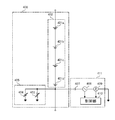
- FIG. 1 is a configuration diagram of a battery pack, a balance circuit, and a leakage detection device according to an embodiment.
- a battery pack having an assembled battery in which four battery cells are connected in series will be described as an example. Further, an example in which the battery pack is mounted on an electric vehicle such as a hybrid vehicle or an electric vehicle will be described. In FIG. 1, the ground is connected to the vehicle body. In practical use, the configuration of the following embodiment may be applied using an arbitrary number of battery cells.
- the battery pack 106 includes an assembled battery 102 and a leakage admittance 105.
- the balance circuit 112 includes a main switch 107, a core 108, a primary winding 109, cell side secondary windings 110a to 110d, and cell switches 111a to 111d.
- the leakage detection device 124 includes a current detection circuit 116, a voltage detection circuit 121, a control unit 122, and a storage unit 123.
- Storage batteries such as lithium ion batteries, lead batteries, nickel cadmium batteries, and nickel metal hydride batteries can be used for the battery cells 101a to 101d.
- the assembled battery 102 is configured by connecting battery cells 101a to 101d in series, and is used as a high-voltage DC power source that is a drive source of an electric vehicle.
- the battery pack 102 is connected to terminals A and A ′ by a system main relay (not shown) or the like (hereinafter referred to as SMR) and connected to a load such as an electric motor or a charger.
- SMR system main relay
- the assembled battery 102 is charged and discharged when connected to a load, and is charged when connected to a charger.
- the assembled battery 102 interrupts
- the insulation resistances 103a to 103d are insulation members such as an insulation member of the battery pack 106 between each of the battery cells 101a to 101d and the vehicle body that is the ground and an insulation portion such as an insulation space that is a space between the battery pack 106 and the vehicle body. Equivalent resistance.
- the resistance values of the insulation resistances 103a to 103d are usually very high and insulate the assembled battery 102 from the vehicle body. However, it is known that the resistance value of the insulation resistances 103a to 103d is lowered when the battery pack 106 is insulated and deteriorated due to aging, scratches, breakage, and deposits of the battery pack 106. When the insulation deterioration of the battery pack 106 proceeds, a leakage current may flow from the assembled battery 102 to the vehicle body.
- the stray capacitances 104a to 104d are equivalent electrostatic capacities of the insulating parts between the battery cells 101a to 101d and the vehicle body that is the ground.
- the stray capacitances 104a to 104d are known to change in capacity due to insulation deterioration of the battery pack 106 or the like.
- the earth leakage admittance 105 is a combined admittance of the insulation resistances 103a to 103d and the stray capacitances 104a to 104d.
- the battery pack 106 is configured by enclosing the assembled battery 102 in a resin container or the like. Thereby, the insulation between the assembled battery 102 and the vehicle body is maintained using a container such as a resin as an insulating member.
- leakage admittance 105 depends on the shape and degree of deterioration of the insulating portion including the insulating member of battery pack 106 and the insulating space that is the space between battery pack 106 and the vehicle body. The value will change.
- the main switch 107 for example, a semiconductor switch such as a field effect transistor can be adopted.
- the main switch 107 is connected in series with the primary winding 109.
- the main switch 107 performs an operation of switching on / off periodically (hereinafter referred to as switching) based on a switching signal input from the control unit 122. Thereby, an alternating current is supplied from the assembled battery 102 to the primary winding 109. Further, the main switch 107 always switches between an on state and an always off state (hereinafter referred to as an on state and an off state) by an on / off signal from the control unit 122.
- an on state and an off state an on / off signal from the control unit 122.
- voltage resistance you may employ
- a ferromagnetic or ferrimagnetic material such as iron or ferrite can be used.
- a primary winding 109, cell side secondary windings 110a to 110d, an ammeter side secondary winding 113, and a voltmeter side secondary winding 117 are wound around the core. That is, the primary winding 109, the cell side secondary windings 110a to 110d, the ammeter side secondary winding 113, and the voltmeter side secondary winding 117 are transformer-coupled.
- the core 108 may be omitted when an air-core coil is sufficient.
- the primary winding 109, the cell side secondary windings 110a to 110d, the ammeter side secondary winding 113, and the voltmeter side secondary winding 117 are configured to be transformer-coupled.
- the primary winding 109 is configured by winding an electric wire such as a copper wire, for example.
- the primary winding 109 is connected to both ends of the assembled battery 102, and an alternating current is supplied from the assembled battery 102 when the main switch 107 is switched.
- a known coil may be used as the primary winding 109 as appropriate.
- the cell-side secondary windings 110a to 110d are configured by winding an electric wire such as a copper wire, for example.
- the cell side secondary windings 110a to 110d have the same number of turns.
- the cell side secondary windings 110a to 110d are connected in parallel to both ends of each of the battery cells 101a to 101d.
- each of the battery cells 101a to 101d (hereinafter referred to as cell voltage 101A to 101D) is lower than the voltage of the assembled battery 102. For this reason, the number of turns of the cell-side secondary windings 110a to 110d is adjusted so as to supply electric power suitable for charging the battery cells 101a to 101d as the number of turns smaller than that of the primary winding 109.
- a known coil may be used as appropriate for the cell side secondary windings 110a to 110d. Further, the number of turns of the cell side secondary windings 110a to 110d may be varied as required. Further, the number of turns of the cell-side secondary windings 110a to 110d may be larger than that of the primary winding 109 as long as a voltage suitable for charging the battery cells 101a to 101d can be obtained.
- the cell switches 111a to 111d are composed of semiconductor switches such as field effect transistors, for example.
- the cell switches 111a to 111d are connected between the battery cells 101a to 101d and the corresponding cell side secondary windings 110a to 110d.
- the cell switches 111a to 111d can be switched between an on state and an off state by an on / off signal from the control unit 122. Accordingly, it is possible to select whether or not to supply power to each of the battery cells 101a to 101d from the assembled battery 102 via the primary winding 109 and each of the cell side secondary windings 110a to 110d.
- an electromagnetic relay may be used when a withstand voltage is required.
- the balance circuit 112 includes a main switch 107, a core 108, a primary winding 109, cell side secondary windings 110a to 110d, and cell switches 111a to 111b.
- the control unit 122 performs control to turn on the cell switches 111a to 111d and switch the main switch 107.
- an alternating current is supplied to the primary winding 109 of the balance circuit 112, and accordingly, the cell side secondary windings 110a to 110d are electromagnetically induced.
- the induced current generated in the cell-side secondary windings 110a to 110d by this electromagnetic induction is supplied to each of the battery cells 101a to 101d via a rectifier circuit and a smoothing circuit (not shown). As a result, the battery cells 101a to 101d are charged.
- the magnitude of the induced current generated by electromagnetic induction of the cell side secondary windings 110a to 110d is inversely proportional to the height of each cell voltage 101A to 101D. Accordingly, a battery cell having a lower cell voltage among the battery cells 101a to 101d is supplied with larger electric power. On the other hand, a battery cell having a higher cell voltage among the battery cells 101a to 101d is supplied with smaller electric power. By continuing this operation, the cell voltages 101A to 101D are equalized.
- the ammeter-side secondary winding 113 is configured by winding an electric wire such as a copper wire, for example.
- the ammeter-side secondary winding 113 has an AC power supply 114 connected in series.
- the primary winding 109 is electromagnetically induced to generate an AC current as an induction current.
- the battery pack 106 is sent. That is, current can be exchanged while the current detection circuit 116 and the battery pack 106 are galvanically insulated.
- a known coil may be used as appropriate for the ammeter-side secondary winding 113.
- the number of turns of the ammeter-side secondary winding 113 may be selected according to the number of turns of the primary winding 109.
- the AC power supply 114 can employ a known AC power supply.
- an output operation signal is input from the control unit 122, an alternating current is supplied to the ammeter-side secondary winding 113.
- the ammeter 115 is connected between the vehicle body and the AC power supply 114, and a known ammeter can be adopted. Then, the current value ⁇ I of the leakage current flowing through the leakage admittance 105 is measured.
- the current detection circuit 116 includes an ammeter-side secondary winding 113, an AC power source 114, and an ammeter 115.
- the current detection circuit 116 is connected to a vehicle body that is a ground. Then, the current detection circuit 116 sends an alternating current from the alternating current power supply 114 to the battery pack 106 and measures the current flowing through the leakage admittance 105 and the vehicle body with the ammeter 115 as a leakage current. Further, the measured current value ⁇ I is output to the control unit 122.
- the voltmeter side secondary winding 117 is configured by winding an electric wire such as a copper wire, for example. And the voltmeter side secondary winding 117 is electromagnetically induced by the alternating current which is output from the alternating current power supply 114 and flows through the ammeter side secondary winding 113, and generates an induced voltage. In addition to the above configuration, a known coil may be used for the voltmeter side secondary winding 117. The number of turns of the voltmeter side secondary winding 117 may be selected according to the number of turns of the primary winding 109 and the ammeter side secondary winding 113.
- the rectifier circuit 118 is configured by a semiconductor element such as a diode, for example.
- the rectifier circuit 118 rectifies the induced voltage generated by electromagnetic induction of the voltmeter side secondary winding 117.
- a simplified rectifier circuit may be used as appropriate, although it is illustrated in a simplified manner.
- the smoothing circuit 119 is composed of, for example, a capacitor.
- the induced voltage rectified by the rectifier circuit 118 is smoothed.
- a simplified smoothing circuit may be used as appropriate, although it is shown in a simplified manner.
- a known voltmeter can be adopted as the voltmeter 120.
- the voltmeter 120 is connected in parallel to the voltmeter side secondary winding 117 and measures the voltage value ⁇ V of the induced voltage applied through the rectifier circuit 118 and the smoothing circuit 119. Further, the measured voltage value ⁇ V is output to the control unit 122.
- the voltage detection circuit 121 includes a voltmeter side secondary winding 117, a rectifier circuit 118, a smoothing circuit 119, and a voltmeter 120.
- the voltage detection circuit 121 is connected to a vehicle body that is a ground.
- the control unit 122 for example, a computer having a memory mounted as a work space such as an ECU (Electronic Control Unit) can be employed.
- control unit 122 determines the start of leakage detection using a signal indicating that leakage detection is started (hereinafter referred to as a control start signal) as a trigger.
- control start signal may be input in an arbitrary configuration such as a user input using an input unit (not shown).
- the ECU 122 may be set to count the clock of the ECU and start the leakage detection every predetermined time. It is good to set so that the control part 122 may start an electrical leakage detection not only with the above structure but at a required timing.
- control unit 122 determines the start of leakage detection, it outputs an on / off signal to the main switch 107 to turn on the main switch 107. In addition, the control unit 122 outputs an on / off signal to the cell switches 111a to 111d to turn off the cell switches 111a to 111d. Further, a system main relay (not shown) is turned off to disconnect the assembled battery 102 from the load and the charger.
- FIG. 2 shows an equivalent circuit of the battery pack, the balance circuit, and the leakage detection device at this time.
- the insulation resistors 103a to 103d are combined to form the insulation resistor 103. Also.
- the stray capacitances 104a to 104d are combined into a stray capacitance 104.
- an output operation signal is output to the AC power source 114, and an AC current is output from the AC power source 114.
- the control unit 122 acquires the current value ⁇ I measured by the ammeter 115 and the voltage value ⁇ V measured by the voltmeter 120.
- the acquisition of the current value ⁇ I and the voltage value ⁇ V may be automatically transmitted and acquired when the respective values are measured by the ammeter 115 and the voltmeter 120, or may be acquired by the control unit 122 as necessary. May be acquired by outputting an acquisition request.
- control unit 122 compares the upper limit value Im of the leakage current and the current value ⁇ I stored in the storage unit 123. As a result, when the current value ⁇ I is smaller than the upper limit value Im, the control unit 122 determines that the battery pack 106 is not leaking. Conversely, when the current value ⁇ I is equal to or greater than the upper limit value Im, the control unit 122 determines that there is a possibility that the battery pack 106 is leaking.
- control unit 122 compares the induced voltage upper limit value Vm stored in the storage unit 123 with the voltage value ⁇ V. As a result, when voltage value ⁇ V is lower than upper limit value Vm, control unit 122 determines that battery pack 106 is not leaking. Conversely, when the voltage value ⁇ V is equal to or greater than the upper limit value Vm, the control unit 122 determines that there is a possibility that the battery pack 106 is leaking.
- the control unit 122 determines that the battery pack 106 is leaking when the current value ⁇ I is equal to or higher than the upper limit value Im and the voltage value ⁇ V is equal to or higher than the upper limit value Vm. In other cases, it is determined that the battery pack 106 is not leaking.
- control unit 122 determines that the battery pack 106 is leaking, the control unit 122 outputs a signal for notifying the leakage to a display device, a communication device, a speaker, or the like (not shown), and notifies the user of the leakage of the battery pack 106. .
- the storage unit 123 stores an OS program and an application program. Further, the storage unit 123 stores various data necessary for the processing of the control unit 122. These various data include the upper limit value Im and the upper limit value Vm. Note that the upper limit value Im and the upper limit value Vm are values for determining that electric leakage has occurred when the current value ⁇ I and the voltage value ⁇ V are higher than the upper limit value Im and the upper limit value Vm, respectively. The upper limit value Im and the upper limit value Vm are determined by experiments, and appropriate values are stored depending on the configuration and installation method of the battery pack 106.
- the earth leakage detection device 124 includes a current detection circuit 116, a voltage detection circuit 121, a control unit 122, and a storage unit 123.
- the leakage detector 124 detects a leakage of the battery pack 106 in a state where it is galvanically insulated from the battery pack 106 by a transformer.
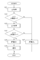
- FIG. 3 is a flowchart of leakage detection according to the embodiment.
- the control unit 122 determines that the leakage detection is started, the main switch 107 is turned on, the cell switches 111a to 111d are turned off, and the SMR is turned off.
- the control unit 122 outputs an output operation signal to the AC power source 114. Then, the AC power supply 114 outputs an AC current and supplies the AC current to the ammeter-side secondary winding 113.
- the primary winding 109 is electromagnetically induced by the alternating current flowing through the ammeter-side secondary winding 113, and an induced current is generated.
- the leakage current flows through the leakage admittance 105 and the vehicle body, and the current value ⁇ I is measured by the ammeter 115. (S301).
- the ammeter 115 transmits the measured current value ⁇ I to the control unit 122.
- the control unit 122 acquires the upper limit value Im stored in the storage unit 123 and determines whether or not the current value ⁇ I is equal to or higher than the upper limit value Im (S302). As a result, when current value ⁇ I is equal to or larger than upper limit value Im (Yes in S302), it is determined that battery pack 106 may be leaked, and the process proceeds to S303.
- control part 122 acquires voltage value (DELTA) V measured with the voltmeter 120 (S303).
- the upper limit value Vm stored in the storage unit 123 is acquired, and it is determined whether or not the voltage value ⁇ V is equal to or higher than the upper limit value Vm (S304).
- control unit 122 outputs a signal indicating that there is a leakage to a display device, communication device, speaker, or the like (not shown), and notifies the user of the leakage of the battery pack 106 (S306). And a series of operation
- control unit 122 determines that battery pack 106 is not leaking (S307). And a series of operation
- control unit 122 determines that battery pack 106 is not leaking (S307). And a series of operation
- the magnitudes of the current value ⁇ I and the upper limit value Im are determined first, but the magnitudes of the voltage value ⁇ V and the upper limit value Vm may be determined first. That is, the order of S301, S302 and S303, S304 may be changed.
- the leakage detection device 124 and the battery pack 106 are coupled by a transformer, and the leakage current is detected by sending an alternating current from the AC power supply 114 of the leakage detection device 124 to the battery pack 106.
- the battery pack 106 and the vehicle body that is the ground can be insulated in a DC manner.
- the primary winding 109 for sending an alternating current to the battery pack 106 is shared with the primary winding of the transformer type balance circuit. Therefore, when mounting a balance circuit and a leakage detection device, the circuit scale can be reduced.
- the determination in S302 may be made after removing the influence of the stray capacitance 104 by using a vector calculation for the current value ⁇ I. As a result, a more accurate leakage detection determination can be made.
- the leakage detection is complementarily determined using the detection results of the current detection circuit 116 and the voltage detection circuit 121, it is possible to detect the deterioration of the insulation resistance with high accuracy.
- control unit 122 may acquire the voltage value of the AC voltage of the AC power supply 114. Then, the controller 122 calculates the leakage admittance 105 of the battery pack 106 from the acquired voltage value ⁇ I of the leakage current and the voltage value of the AC voltage of the AC power supply 114. Further, the control unit 122 acquires a phase difference from the phase of the acquired voltage value ⁇ I of the leakage current and the phase of the voltage value of the AC voltage of the AC power supply 114. Then, a resistance component that is a real part of the leakage admittance 105 may be calculated from the calculated phase difference and the absolute value of the leakage admittance 105. As a result, the control unit 122 detects the leakage of the battery pack 106 by comparing the calculated resistance component with the leakage reference value of the resistance component determined in advance by experiment and stored in the storage unit 123. May be.
Landscapes
- Engineering & Computer Science (AREA)
- Power Engineering (AREA)
- Life Sciences & Earth Sciences (AREA)
- Sustainable Development (AREA)
- Sustainable Energy (AREA)
- Transportation (AREA)
- Mechanical Engineering (AREA)
- Physics & Mathematics (AREA)
- General Physics & Mathematics (AREA)
- Electric Propulsion And Braking For Vehicles (AREA)
- Testing Of Short-Circuits, Discontinuities, Leakage, Or Incorrect Line Connections (AREA)
- Secondary Cells (AREA)
Applications Claiming Priority (3)
| Application Number | Priority Date | Filing Date | Title |
|---|---|---|---|
| JP2012013114A JP5674688B2 (ja) | 2012-01-25 | 2012-01-25 | 漏電検出装置 |
| JP2012-013114 | 2012-01-25 | ||
| JP2014003947A JP5751351B2 (ja) | 2012-01-25 | 2014-01-14 | 漏電検出装置 |
Publications (1)
| Publication Number | Publication Date |
|---|---|
| WO2013111414A1 true WO2013111414A1 (fr) | 2013-08-01 |
Family
ID=59592339
Family Applications (1)
| Application Number | Title | Priority Date | Filing Date |
|---|---|---|---|
| PCT/JP2012/078656 Ceased WO2013111414A1 (fr) | 2012-01-25 | 2012-11-05 | Dispositif de détection de fuite électrique |
Country Status (2)
| Country | Link |
|---|---|
| JP (2) | JP5674688B2 (fr) |
| WO (1) | WO2013111414A1 (fr) |
Cited By (5)
| Publication number | Priority date | Publication date | Assignee | Title |
|---|---|---|---|---|
| CN104423377A (zh) * | 2013-08-31 | 2015-03-18 | 福特全球技术公司 | 隔离监视器性能工具和测试隔离监视器的方法 |
| WO2016101224A1 (fr) * | 2014-12-25 | 2016-06-30 | 华为技术有限公司 | Système de détection de courant de fuite de terminal |
| US10168372B2 (en) | 2016-12-14 | 2019-01-01 | General Electric Company | System and method for leakage current and fault location detection in electric vehicle DC power circuits |
| US10203363B2 (en) | 2016-12-14 | 2019-02-12 | General Electric Company | DC leakage current detector and method of operation thereof for leakage current detection in DC power circuits |
| EP4607651A4 (fr) * | 2022-12-29 | 2026-04-08 | Huawei Digital Power Tech Co Ltd | Groupe de batteries, système de stockage d'énergie, système d'alimentation sans coupure et véhicule électrique |
Citations (6)
| Publication number | Priority date | Publication date | Assignee | Title |
|---|---|---|---|---|
| JPS59159622A (ja) * | 1983-03-01 | 1984-09-10 | 日本電池株式会社 | 蓄電池設備の地絡検出装置 |
| JPH0763806A (ja) * | 1993-08-30 | 1995-03-10 | Nippondenso Co Ltd | 漏電検出装置 |
| JPH11218554A (ja) * | 1997-10-30 | 1999-08-10 | Matsushita Electric Ind Co Ltd | 電気車両の漏電検出装置 |
| JP2002142371A (ja) * | 2000-10-31 | 2002-05-17 | Nagano Japan Radio Co | 電圧イコライザ |
| JP2003333762A (ja) * | 2002-05-14 | 2003-11-21 | Japan Storage Battery Co Ltd | 組電池用の電圧レベル均等化装置 |
| JP2005020848A (ja) * | 2003-06-25 | 2005-01-20 | Fuji Electric Systems Co Ltd | 自動車の漏電検知システム |
Family Cites Families (6)
| Publication number | Priority date | Publication date | Assignee | Title |
|---|---|---|---|---|
| JPH01161178A (ja) * | 1987-12-17 | 1989-06-23 | Mitsubishi Electric Corp | 磁性体の磁気特性測定装置 |
| JPH0381677A (ja) * | 1989-08-24 | 1991-04-08 | Shimizu Corp | 磁気遮蔽室構成材料の磁気遮蔽性能測定方法及びその測定装置 |
| JPH05244701A (ja) * | 1992-02-26 | 1993-09-21 | Honda Motor Co Ltd | 電動車両内給電線の地絡検出回路 |
| JPH08179017A (ja) * | 1994-12-26 | 1996-07-12 | Bridgestone Corp | 電池インピーダンスのモニタ装置 |
| JPH11218493A (ja) * | 1998-02-03 | 1999-08-10 | Shimadzu Corp | 可搬型発光分光分析装置 |
| US7924019B2 (en) * | 2008-01-16 | 2011-04-12 | Lear Corporation | System and method for fault isolation and leakage current detection |
-
2012
- 2012-01-25 JP JP2012013114A patent/JP5674688B2/ja not_active Expired - Fee Related
- 2012-11-05 WO PCT/JP2012/078656 patent/WO2013111414A1/fr not_active Ceased
-
2014
- 2014-01-14 JP JP2014003947A patent/JP5751351B2/ja not_active Expired - Fee Related
Patent Citations (6)
| Publication number | Priority date | Publication date | Assignee | Title |
|---|---|---|---|---|
| JPS59159622A (ja) * | 1983-03-01 | 1984-09-10 | 日本電池株式会社 | 蓄電池設備の地絡検出装置 |
| JPH0763806A (ja) * | 1993-08-30 | 1995-03-10 | Nippondenso Co Ltd | 漏電検出装置 |
| JPH11218554A (ja) * | 1997-10-30 | 1999-08-10 | Matsushita Electric Ind Co Ltd | 電気車両の漏電検出装置 |
| JP2002142371A (ja) * | 2000-10-31 | 2002-05-17 | Nagano Japan Radio Co | 電圧イコライザ |
| JP2003333762A (ja) * | 2002-05-14 | 2003-11-21 | Japan Storage Battery Co Ltd | 組電池用の電圧レベル均等化装置 |
| JP2005020848A (ja) * | 2003-06-25 | 2005-01-20 | Fuji Electric Systems Co Ltd | 自動車の漏電検知システム |
Cited By (9)
| Publication number | Priority date | Publication date | Assignee | Title |
|---|---|---|---|---|
| CN104423377A (zh) * | 2013-08-31 | 2015-03-18 | 福特全球技术公司 | 隔离监视器性能工具和测试隔离监视器的方法 |
| CN104423377B (zh) * | 2013-08-31 | 2018-07-13 | 福特全球技术公司 | 隔离监视器性能工具和测试隔离监视器的方法 |
| US10882403B2 (en) | 2013-08-31 | 2021-01-05 | Ford Global Technologies, Llc | Vehicle high/low voltage systems isolation testing |
| WO2016101224A1 (fr) * | 2014-12-25 | 2016-06-30 | 华为技术有限公司 | Système de détection de courant de fuite de terminal |
| CN106164686A (zh) * | 2014-12-25 | 2016-11-23 | 华为技术有限公司 | 一种终端的漏电流检测系统 |
| CN106164686B (zh) * | 2014-12-25 | 2019-10-22 | 华为技术有限公司 | 一种终端的漏电流检测系统 |
| US10168372B2 (en) | 2016-12-14 | 2019-01-01 | General Electric Company | System and method for leakage current and fault location detection in electric vehicle DC power circuits |
| US10203363B2 (en) | 2016-12-14 | 2019-02-12 | General Electric Company | DC leakage current detector and method of operation thereof for leakage current detection in DC power circuits |
| EP4607651A4 (fr) * | 2022-12-29 | 2026-04-08 | Huawei Digital Power Tech Co Ltd | Groupe de batteries, système de stockage d'énergie, système d'alimentation sans coupure et véhicule électrique |
Also Published As
| Publication number | Publication date |
|---|---|
| JP5751351B2 (ja) | 2015-07-22 |
| JP2014098710A (ja) | 2014-05-29 |
| JP5674688B2 (ja) | 2015-02-25 |
| JP2013152144A (ja) | 2013-08-08 |
Similar Documents
| Publication | Publication Date | Title |
|---|---|---|
| EP3130932B1 (fr) | Dispositif et procédé de mesure de la résistance d'isolation permettant de mesurer rapidement la résistance d'isolation | |
| US9851405B2 (en) | Method and apparatus for detecting state of relay | |
| JP5524019B2 (ja) | 充電装置、及び充電方法 | |
| JP5751351B2 (ja) | 漏電検出装置 | |
| JP6697869B2 (ja) | 状態判定装置および状態判定方法 | |
| US9851413B2 (en) | Method and apparatus for estimating current | |
| US20130307471A1 (en) | Vehicle, power transmitting device and contactless power supply system | |
| US10189367B2 (en) | Electric vehicle quick charge control apparatus | |
| JP6146332B2 (ja) | リレーの固着判別システム | |
| WO2016208745A1 (fr) | Procédé et système d'estimation d'un état de charge ou d'une profondeur de décharge de batterie, et procédé et système pour évaluer l'intégrité d'une batterie | |
| KR20140041621A (ko) | 절연물의 결함을 검출하는 디바이스 | |
| CN102651624A (zh) | 马达驱动装置 | |
| KR20160064089A (ko) | 축전 장치, 축전 제어 장치 및 축전 제어 방법 | |
| WO2014027512A1 (fr) | Appareil d'alimentation électrique | |
| WO2014115294A1 (fr) | Dispositif de contrôle de batterie, système de batterie | |
| KR101759532B1 (ko) | 배터리의 내부 임피던스를 추정하는 방법 | |
| CN110192318A (zh) | 向多个储能部件供应能量和/或提供能量的设备和方法 | |
| JP6003429B2 (ja) | 測定装置 | |
| JP7424592B2 (ja) | 装置およびバッテリーパック | |
| CN114846720A (zh) | 无线充电系统、无线充电方法和电动车辆 | |
| JP7173698B2 (ja) | 車両用非接触受電システム | |
| WO2013129602A1 (fr) | Dispositif d'équilibrage de cellule | |
| TW201937826A (zh) | 充電裝置、充電排序方法與電量偵測方法 | |
| WO2013133265A1 (fr) | Dispositif d'équilibrage de cellule | |
| JP6378585B2 (ja) | 過渡電流測定方法、過渡電流測定可能な商用配電系判定方法、並びに過渡電流測定不可能な商用配電系への対策方法及びそのための装置 |
Legal Events
| Date | Code | Title | Description |
|---|---|---|---|
| 121 | Ep: the epo has been informed by wipo that ep was designated in this application |
Ref document number: 12866828 Country of ref document: EP Kind code of ref document: A1 |
|
| NENP | Non-entry into the national phase |
Ref country code: DE |
|
| 122 | Ep: pct application non-entry in european phase |
Ref document number: 12866828 Country of ref document: EP Kind code of ref document: A1 |