WO2013111428A1 - Matériau de support pour dispositif de traitement de gaz, dispositif de traitement de gaz et procédés de production associés - Google Patents
Matériau de support pour dispositif de traitement de gaz, dispositif de traitement de gaz et procédés de production associés Download PDFInfo
- Publication number
- WO2013111428A1 WO2013111428A1 PCT/JP2012/079564 JP2012079564W WO2013111428A1 WO 2013111428 A1 WO2013111428 A1 WO 2013111428A1 JP 2012079564 W JP2012079564 W JP 2012079564W WO 2013111428 A1 WO2013111428 A1 WO 2013111428A1
- Authority
- WO
- WIPO (PCT)
- Prior art keywords
- holding material
- casing
- processing structure
- alumina sol
- gas
- Prior art date
- Legal status (The legal status is an assumption and is not a legal conclusion. Google has not performed a legal analysis and makes no representation as to the accuracy of the status listed.)
- Ceased
Links
Images


Classifications
-
- C—CHEMISTRY; METALLURGY
- C04—CEMENTS; CONCRETE; ARTIFICIAL STONE; CERAMICS; REFRACTORIES
- C04B—LIME, MAGNESIA; SLAG; CEMENTS; COMPOSITIONS THEREOF, e.g. MORTARS, CONCRETE OR LIKE BUILDING MATERIALS; ARTIFICIAL STONE; CERAMICS; REFRACTORIES; TREATMENT OF NATURAL STONE
- C04B35/00—Shaped ceramic products characterised by their composition; Ceramics compositions; Processing powders of inorganic compounds preparatory to the manufacturing of ceramic products
- C04B35/71—Ceramic products containing macroscopic reinforcing agents
- C04B35/74—Ceramic products containing macroscopic reinforcing agents containing shaped metallic materials
- C04B35/76—Fibres, filaments, whiskers, platelets, or the like
-
- D—TEXTILES; PAPER
- D21—PAPER-MAKING; PRODUCTION OF CELLULOSE
- D21H—PULP COMPOSITIONS; PREPARATION THEREOF NOT COVERED BY SUBCLASSES D21C OR D21D; IMPREGNATING OR COATING OF PAPER; TREATMENT OF FINISHED PAPER NOT COVERED BY CLASS B31 OR SUBCLASS D21G; PAPER NOT OTHERWISE PROVIDED FOR
- D21H13/00—Pulp or paper, comprising synthetic cellulose or non-cellulose fibres or web-forming material
- D21H13/36—Inorganic fibres or flakes
- D21H13/38—Inorganic fibres or flakes siliceous
-
- B—PERFORMING OPERATIONS; TRANSPORTING
- B28—WORKING CEMENT, CLAY, OR STONE
- B28B—SHAPING CLAY OR OTHER CERAMIC COMPOSITIONS; SHAPING SLAG; SHAPING MIXTURES CONTAINING CEMENTITIOUS MATERIAL, e.g. PLASTER
- B28B1/00—Producing shaped prefabricated articles from the material
- B28B1/14—Producing shaped prefabricated articles from the material by simple casting, the material being neither forcibly fed nor positively compacted
-
- C—CHEMISTRY; METALLURGY
- C03—GLASS; MINERAL OR SLAG WOOL
- C03C—CHEMICAL COMPOSITION OF GLASSES, GLAZES OR VITREOUS ENAMELS; SURFACE TREATMENT OF GLASS; SURFACE TREATMENT OF FIBRES OR FILAMENTS MADE FROM GLASS, MINERALS OR SLAGS; JOINING GLASS TO GLASS OR OTHER MATERIALS
- C03C13/00—Fibre or filament compositions
- C03C13/005—Fibre or filament compositions obtained by leaching of a soluble phase and consolidation
-
- F—MECHANICAL ENGINEERING; LIGHTING; HEATING; WEAPONS; BLASTING
- F01—MACHINES OR ENGINES IN GENERAL; ENGINE PLANTS IN GENERAL; STEAM ENGINES
- F01N—GAS-FLOW SILENCERS OR EXHAUST APPARATUS FOR MACHINES OR ENGINES IN GENERAL; GAS-FLOW SILENCERS OR EXHAUST APPARATUS FOR INTERNAL-COMBUSTION ENGINES
- F01N3/00—Exhaust or silencing apparatus having means for purifying, rendering innocuous, or otherwise treating exhaust
- F01N3/02—Exhaust or silencing apparatus having means for purifying, rendering innocuous, or otherwise treating exhaust for cooling, or for removing solid constituents of, exhaust
- F01N3/021—Exhaust or silencing apparatus having means for purifying, rendering innocuous, or otherwise treating exhaust for cooling, or for removing solid constituents of, exhaust by means of filters
- F01N3/0211—Arrangements for mounting filtering elements in housing, e.g. with means for compensating thermal expansion or vibration
-
- F—MECHANICAL ENGINEERING; LIGHTING; HEATING; WEAPONS; BLASTING
- F01—MACHINES OR ENGINES IN GENERAL; ENGINE PLANTS IN GENERAL; STEAM ENGINES
- F01N—GAS-FLOW SILENCERS OR EXHAUST APPARATUS FOR MACHINES OR ENGINES IN GENERAL; GAS-FLOW SILENCERS OR EXHAUST APPARATUS FOR INTERNAL-COMBUSTION ENGINES
- F01N3/00—Exhaust or silencing apparatus having means for purifying, rendering innocuous, or otherwise treating exhaust
- F01N3/08—Exhaust or silencing apparatus having means for purifying, rendering innocuous, or otherwise treating exhaust for rendering innocuous
- F01N3/10—Exhaust or silencing apparatus having means for purifying, rendering innocuous, or otherwise treating exhaust for rendering innocuous by thermal or catalytic conversion of noxious components of exhaust
- F01N3/24—Exhaust or silencing apparatus having means for purifying, rendering innocuous, or otherwise treating exhaust for rendering innocuous by thermal or catalytic conversion of noxious components of exhaust characterised by constructional aspects of converting apparatus
- F01N3/28—Construction of catalytic reactors
- F01N3/2803—Construction of catalytic reactors characterised by structure, by material or by manufacturing of catalyst support
- F01N3/2835—Construction of catalytic reactors characterised by structure, by material or by manufacturing of catalyst support fibrous
-
- F—MECHANICAL ENGINEERING; LIGHTING; HEATING; WEAPONS; BLASTING
- F01—MACHINES OR ENGINES IN GENERAL; ENGINE PLANTS IN GENERAL; STEAM ENGINES
- F01N—GAS-FLOW SILENCERS OR EXHAUST APPARATUS FOR MACHINES OR ENGINES IN GENERAL; GAS-FLOW SILENCERS OR EXHAUST APPARATUS FOR INTERNAL-COMBUSTION ENGINES
- F01N3/00—Exhaust or silencing apparatus having means for purifying, rendering innocuous, or otherwise treating exhaust
- F01N3/08—Exhaust or silencing apparatus having means for purifying, rendering innocuous, or otherwise treating exhaust for rendering innocuous
- F01N3/10—Exhaust or silencing apparatus having means for purifying, rendering innocuous, or otherwise treating exhaust for rendering innocuous by thermal or catalytic conversion of noxious components of exhaust
- F01N3/24—Exhaust or silencing apparatus having means for purifying, rendering innocuous, or otherwise treating exhaust for rendering innocuous by thermal or catalytic conversion of noxious components of exhaust characterised by constructional aspects of converting apparatus
- F01N3/28—Construction of catalytic reactors
- F01N3/2839—Arrangements for mounting catalyst support in housing, e.g. with means for compensating thermal expansion or vibration
- F01N3/2853—Arrangements for mounting catalyst support in housing, e.g. with means for compensating thermal expansion or vibration using mats or gaskets between catalyst body and housing
-
- F—MECHANICAL ENGINEERING; LIGHTING; HEATING; WEAPONS; BLASTING
- F01—MACHINES OR ENGINES IN GENERAL; ENGINE PLANTS IN GENERAL; STEAM ENGINES
- F01N—GAS-FLOW SILENCERS OR EXHAUST APPARATUS FOR MACHINES OR ENGINES IN GENERAL; GAS-FLOW SILENCERS OR EXHAUST APPARATUS FOR INTERNAL-COMBUSTION ENGINES
- F01N2310/00—Selection of sound absorbing or insulating material
- F01N2310/02—Mineral wool, e.g. glass wool, rock wool, asbestos or the like
-
- Y—GENERAL TAGGING OF NEW TECHNOLOGICAL DEVELOPMENTS; GENERAL TAGGING OF CROSS-SECTIONAL TECHNOLOGIES SPANNING OVER SEVERAL SECTIONS OF THE IPC; TECHNICAL SUBJECTS COVERED BY FORMER USPC CROSS-REFERENCE ART COLLECTIONS [XRACs] AND DIGESTS
- Y02—TECHNOLOGIES OR APPLICATIONS FOR MITIGATION OR ADAPTATION AGAINST CLIMATE CHANGE
- Y02T—CLIMATE CHANGE MITIGATION TECHNOLOGIES RELATED TO TRANSPORTATION
- Y02T10/00—Road transport of goods or passengers
- Y02T10/10—Internal combustion engine [ICE] based vehicles
- Y02T10/12—Improving ICE efficiencies
-
- Y—GENERAL TAGGING OF NEW TECHNOLOGICAL DEVELOPMENTS; GENERAL TAGGING OF CROSS-SECTIONAL TECHNOLOGIES SPANNING OVER SEVERAL SECTIONS OF THE IPC; TECHNICAL SUBJECTS COVERED BY FORMER USPC CROSS-REFERENCE ART COLLECTIONS [XRACs] AND DIGESTS
- Y10—TECHNICAL SUBJECTS COVERED BY FORMER USPC
- Y10T—TECHNICAL SUBJECTS COVERED BY FORMER US CLASSIFICATION
- Y10T29/00—Metal working
- Y10T29/49—Method of mechanical manufacture
- Y10T29/49345—Catalytic device making
Definitions
- the present invention relates to a holding material for a gas processing device, a gas processing device, and a manufacturing method thereof, and particularly relates to an improvement in holding power of the holding material.
- Vehicles such as automobiles are equipped with a catalytic converter for removing harmful substances such as carbon monoxide, hydrocarbons and nitrogen oxides contained in exhaust gas.
- the catalytic converter include a cylindrical catalyst carrier, a cylindrical metal casing that houses the catalyst carrier, and a mat-like inorganic fiber holding material disposed between the catalyst carrier and the casing. There is something with.
- the present invention has been made in view of the above-described problems, and provides a holding member for a gas processing apparatus, a gas processing apparatus, and a manufacturing method thereof that are inexpensive, simple in structure, and exhibit high holding power. Is one of its purposes.
- a holding member for a gas processing apparatus includes a processing structure and a casing that accommodates the processing structure, wherein the processing structure and the casing are provided. It is made of silica fibers and contains 3 parts by mass or more of alumina sol in terms of solid content with respect to 100 parts by mass of the silica fibers. According to the present invention, it is possible to provide a holding member for a gas processing apparatus that is inexpensive, has a simple structure, and exhibits high holding power.
- a holding member for a gas processing apparatus includes a processing structure and a casing that accommodates the processing structure, wherein the processing structure and the casing are provided.
- the surface pressure during 1000 cycles of expansion is 1.2 times or more of that in the case where the alumina sol is not included. According to the present invention, it is possible to provide a holding member for a gas processing apparatus that is inexpensive, has a simple structure, and exhibits a high holding force.
- a holding member for a gas processing apparatus includes a processing structure and a casing that accommodates the processing structure, wherein the processing structure and the casing are provided.
- the surface pressure at the time of expansion of 1000 cycles is 1.5 times or more than that when the alumina sol is not included. According to the present invention, it is possible to provide a holding member for a gas processing apparatus that is inexpensive, has a simple structure, and exhibits a high holding force.
- a gas processing apparatus for solving the above problems is disposed between a processing structure, a casing that houses the processing structure, and the processing structure and the casing.
- One of the above holding materials is provided.
- ADVANTAGE OF THE INVENTION According to this invention, the gas processing apparatus which is cheap, has a simple structure, and exhibits high holding power can be provided.
- a method for manufacturing a holding member for a gas processing device for solving the above-described problem is provided in a gas processing device including a processing structure and a casing that houses the processing structure. And a holding material disposed between the casing and a wet slurry of a slurry containing silica fibers and 3 parts by mass or more of alumina sol in terms of solid content with respect to 100 parts by mass of the silica fibers
- the holding material is manufactured by molding.
- a method for manufacturing a holding member for a gas processing device for solving the above-described problem is provided in a gas processing device including a processing structure and a casing that houses the processing structure. And a holding material disposed between the casing and the casing, comprising silica fibers, an initial bulk density of 0.3 to 0.5 g / cm 3 , a temperature of 700 to 900 ° C., and a stroke amount of By wet forming of a slurry containing an amount of alumina sol in which the surface pressure of the holding material at the time of expansion of 1000 cycles in an expansion / compression test of 0.2 mm is 1.2 times or more that when the alumina sol is not included.
- the holding material is manufactured.
- ADVANTAGE OF THE INVENTION According to this invention, the manufacturing method of the holding
- a method for manufacturing a holding member for a gas processing device for solving the above-described problem is provided in a gas processing device including a processing structure and a casing that houses the processing structure. And a holding material disposed between the casing and the casing, comprising silica fibers, an initial bulk density of 0.3 to 0.5 g / cm 3 , a temperature of 240 to 300 ° C., and a stroke amount of By wet molding of a slurry containing an amount of alumina sol in which the surface pressure of the holding material at the time of expansion of 1000 cycles in an expansion / compression test of 0.08 mm is 1.5 times or more that when the alumina sol is not included.
- the holding material is manufactured.
- ADVANTAGE OF THE INVENTION According to this invention, the manufacturing method of the holding
- the manufacturing method of the gas processing apparatus concerning one embodiment of the present invention for solving the above-mentioned subject is arranged between a processing structure, a casing which stores the processing structure, and the processing structure and the casing.
- a method of manufacturing a gas processing apparatus comprising a holding material comprising: placing any one of the holding materials between the processing structure and the casing.
- a holding member for a gas processing device, a gas processing device, and a method for manufacturing them which are inexpensive, have a simple structure, and exhibit high holding power.
- FIG. 1 is an explanatory diagram showing an example of a gas processing apparatus 1 according to the present embodiment.
- a part of the casing 40 is omitted, and the processing structure 20 and the holding material 10 accommodated in the casing 40 are exposed.
- FIG. 2 is an explanatory diagram showing an example of a cross section of the gas treatment device 1 cut in the longitudinal direction (the direction indicated by the arrow X shown in FIGS. 1 and 2). 1 and 2, an arrow X indicates a direction in which gas flows in the gas processing apparatus 1.
- FIG. 3 is an explanatory diagram showing an example of the holding member 10 for a gas processing device according to the present embodiment in a plan view.
- FIG. 4 is an explanatory view showing an example of a cross section of the holding member 10 cut along the line IV-IV shown in FIG.
- the gas processing apparatus 1 is disposed between a processing structure 20, a casing 40 that houses the processing structure 20, and the processing structure 20 and the casing 40. Holding material 10.
- the gas treatment device 1 is used for treating gas such as gas purification. That is, the gas processing apparatus 1 is an exhaust gas processing apparatus used for purifying exhaust gas, for example. Specifically, the gas processing apparatus 1 is provided for processing harmful substances and / or particles contained in exhaust gas discharged from an internal combustion engine (gasoline engine, diesel engine, etc.) in a vehicle such as an automobile. . In this case, the temperature of the gas flowing through the gas processing apparatus 1 is not particularly limited, but is, for example, 200 to 950 ° C.
- the gas processing device 1 is a catalytic converter used for removing harmful substances contained in exhaust gas of a gasoline engine in a vehicle such as an automobile.
- the gas processing apparatus 1 may be, for example, a DPF (Diesel particulate filter) used to remove particles contained in the exhaust gas of a deal engine.
- DPF Diesel particulate filter
- the processing structure 20 is a structure having a function of processing a gas. That is, as shown in the examples of FIGS. 1 and 2, when the gas processing device 1 is a catalytic converter, the processing structure 20 includes a catalyst for purifying gas and a catalyst that supports the catalyst. It is a carrier.
- the catalyst is a catalyst for removing harmful substances (carbon monoxide, hydrocarbons, nitrogen oxides, etc.) contained in a gas such as exhaust gas. More specifically, the catalyst is, for example, a metal catalyst such as a noble metal catalyst.
- the carrier for supporting the catalyst is, for example, a tubular molded body (for example, a cylindrical honeycomb-shaped molded body) made of an inorganic material such as ceramics (such as cordierite).
- the processing structure 20 is a structure having a filter that captures the particles in the gas.
- the processing structure 20 may not have a catalyst.
- the casing 40 is a cylindrical body in which a space capable of accommodating the processing structure 20 is formed.
- the casing 40 is made of metal, for example.
- the metal which comprises the casing 40 is not specifically limited, For example, it selects from the group which consists of stainless steel, iron, and aluminum.
- the casing 40 may be a cylindrical body that can be divided into two along the longitudinal direction of the gas processing apparatus 1, or may be an integral cylindrical body that is not divided. In the example shown in FIGS. 1 and 2, the casing 40 is an integral cylindrical body.
- the holding material 10 is used for holding the processing structure 20 in the casing 40. In other words, the holding material 10 is pressed into the gap between the casing 40 and the processing structure 20 to stably hold the processing structure 20 in the casing 40.
- the holding material 10 is still purified, for example, with a function of safely holding the processing structure 20 so as to avoid the processing structure 20 from colliding with the casing 40 and being damaged by vibration or the like in the gas processing apparatus 1. It is required to have a function of sealing the gap so that a gas that is not leaked from the gap between the processing structure 20 and the casing 40 to the downstream side.
- the holding material 10 is used for the gas processing apparatus 1 provided in order to process the harmful substance contained in the exhaust gas discharged
- the holding material 10 may be used in a relatively high temperature (800 to 950 ° C.) environment such as a gasoline engine, or a relatively low temperature (500 or less such as a diesel engine (eg, DPF)). It may be used in an environment of ⁇ 700 ° C.).
- the holding material 10 is made of silica fiber. That is, the holding material 10 is a molded body mainly composed of silica fibers. Specifically, the holding material 10 may be, for example, a molded body containing 85 mass% or more of silica fibers, or a molded body containing 90 mass% or more of silica fibers, and 95 mass% of silica fibers. It is good also as a molded object containing% or more.
- the upper limit value of the silica fiber content in the holding material 10 is not particularly limited as long as the holding material 10 contains alumina sol in an amount described later, but the silica fiber content is, for example, 97% by mass. It may be the following.
- the silica fiber is an inorganic fiber mainly composed of silica (SiO 2 ).
- the silica fiber may be an amorphous fiber or a crystalline fiber, and is particularly preferably an amorphous fiber in terms of excellent flexibility.
- the silica fiber may contain, for example, 90% by mass or more of silica, 95% by mass or more, or 97% by mass or more.
- the upper limit of the content of silica in the silica fiber is not particularly limited, the content of the silica may be 99% by mass or less, for example.
- the silica fiber may further contain a component other than silica. That is, the silica fiber may further contain, for example, alumina (Al 2 O 3 ). In this case, the silica fiber may contain, for example, 3% by mass or less of alumina. That is, the content of alumina in the silica fiber may be, for example, 0 to 3% by mass or 1 to 3% by mass.
- silica fiber one that has been heat-treated (baked) in advance may be used. By heat-treating the silica fiber in advance, the heat resistance of the silica fiber can be improved.
- the silica fiber can be obtained by removing the alkali component by applying an acid treatment to the glass fiber to increase the silica component.
- an acid treatment to increase the silica component.
- the average fiber diameter of the silica fiber is preferably 5 to 8 ⁇ m, for example.
- the average fiber length of the silica fibers is preferably 4 to 15 mm, for example.
- the holding material 10 contains a relatively large amount of alumina sol. That is, the inventors of the present invention have made extensive studies on technical means for increasing the holding power of the inorganic fiber holding material, and as a result, silica that has not been used so far in the holding material as the inorganic fiber. Using a fiber and a relatively large amount of alumina sol (for example, an amount not conventionally used when used as an inorganic binder) for the silica fiber, the holding power of the holding material is remarkable. The present inventors have completed the present invention by independently obtaining the unexpected knowledge of increasing the speed.
- alumina sol for example, an amount not conventionally used when used as an inorganic binder
- the holding material 10 is made of, for example, silica fiber, includes alumina sol, an initial bulk density of 0.3 to 0.5 g / cm 3 , a temperature of 700 to 900 ° C., and a stroke amount of 0.2 mm. /
- the surface pressure at the time of expansion of 1000 cycles may be 1.2 times or more of that when the alumina sol is not included, or may be 1.3 times or more.
- the holding material 10 has an initial bulk density of 0.3 to 0.5 g / cm 3 , a temperature of 240 to 300 ° C., and a stroke amount of 0.08 mm.
- the surface pressure may be 1.5 times or more that when alumina sol is not included, or may be 2 times or more.
- the bulk density of the holding material 10 before being subjected to the test is smaller than the initial bulk density in the test. That is, in the expansion / compression test, for example, the holding material 10 having a bulk density of 0.1 to 0.2 g / cm 3 is treated with an initial bulk density (bulk density at the start of the first cycle of the test). It may be used after being compressed so that it becomes 0.3 to 0.5 g / cm 3 .
- the holding material 10 includes an amount of alumina sol that exhibits a surface pressure as described above.
- the amount of alumina sol contained in this holding material 10 is, for example, producing a plurality of candidate holding materials having different alumina sol contents (a plurality of holding materials having the same structure except that the alumina sol content is different)
- the surface pressure in the expansion / compression test described above is evaluated, and based on the result of the evaluation, the surface pressure during expansion of 1000 cycles is a comparative holding material that does not contain alumina sol (except that it does not contain alumina sol). It can be determined based on the alumina sol content of the candidate holding material which is a predetermined multiple of that of the holding material having the same structure as the candidate holding material.
- the holding material 10 may include, for example, 3 parts by mass or more of alumina sol in terms of solid content with respect to 100 parts by mass of silica fiber, and 4 parts by mass or more of alumina sol in terms of solid content. It may be included.
- the upper limit of the content of the alumina sol is not particularly limited as long as the holding material 10 has a desired characteristic (for example, a range in which the holding material 10 exhibits the above surface pressure). It is good also as containing 15 mass parts or less alumina sol in conversion of solid content with respect to 100 mass parts of fibers, and good also as containing 10 mass parts or less of alumina sol.
- the holding material 10 may contain, for example, 3 to 15 parts by mass or 3 to 10 parts by mass of alumina sol in terms of solid content with respect to 100 parts by mass of silica fibers.
- the holding material 10 may contain, for example, 4 to 15 parts by mass or 4 to 10 parts by mass of alumina sol in terms of solid content with respect to 100 parts by mass of silica fibers.
- the alumina sol is not particularly limited as long as it has fluidity and contains alumina fine particles dispersed in a solvent (for example, a solvent containing water).
- the alumina sol is produced, for example, by adding an aqueous aluminum sulfate solution to an aqueous solution of sodium aluminate to neutralize it, adding an acid to the resulting aggregate and dispersing the aggregate.
- the holding material 10 may further include components other than silica fibers and alumina sol. That is, the holding material 10 may further include an organic binder, for example.
- an organic binder is not specifically limited, For example, it is good also as using 1 or more types selected from the group which consists of rubber
- the content of the organic binder in the holding material 10 is not particularly limited, and may be, for example, 10% by mass or less (0 to 10% by mass) in terms of solid content with respect to 100 parts by mass of silica fiber. .
- the bulk density of the holding material 10 is in a desired range in a state where the holding material 10 is incorporated in the gas processing apparatus 1 (that is, the holding material 10 is press-fitted between the processing structure 20 and the casing 40). It may be set appropriately so as to be, and is not particularly limited.
- the bulk density of the holding material 10 is appropriately set according to a gap (gap) between the processing structure 20 and the casing 40, for example.
- the bulk density of the holding material 10 may be, for example, 0.1 to 0.2 g / cm 3 .
- the bulk density of the holding material 10 after being incorporated in the gas processing device 1 may be, for example, 0.2 to 0.7 g / cm 3 .
- the basis weight of the holding material 10 is not particularly limited as long as it is appropriately set so as to be in a desired range in a state where the holding material 10 is incorporated in the gas processing apparatus 1.
- the basis weight of the holding material 10 may be, for example, 1000 to 3400 g / m 2 .
- the shape of the holding material 10 is not particularly limited as long as the processing structure 20 can be held in the casing 40.
- the holding material 10 is, for example, a plate-like body (film, sheet, blanket, mat, etc.). It may be, or may be a cylindrical body. In the example shown in FIGS. 1 to 4, the holding member 10 is a plate-like body.
- one end and the other end of the plate-like body may be formed in a corresponding shape that can be fitted. That is, in the example shown in FIG. 3, the one end and the other end of the holding material 10 are respectively formed in a corresponding convex shape and concave shape. As shown in FIG. 1, one end and the other end of the holding member 10 disposed on the outer periphery of the processing structure 20 are fitted.
- the holding material 10 can be preferably manufactured by wet molding of a slurry containing silica fibers and the above-mentioned amount of alumina sol.
- the holding material 10 includes, for example, silica fibers and 1000 cycles in an expansion / compression test in which an initial bulk density is 0.3 to 0.5 g / cm 3 , a temperature is 700 to 900 ° C., and a stroke amount is 0.2 mm.
- the surface pressure of the holding material 10 at the time of expansion is manufactured by wet molding of a slurry containing alumina sol in an amount that is 1.2 times or more, or 1.3 times or more that when no alumina sol is included. It is good.
- the holding material 10 is, for example, silica fiber and 1000 cycles in an expansion / compression test in which the initial bulk density is 0.3 to 0.5 g / cm 3 , the temperature is 240 to 300 ° C., and the stroke amount is 0.08 mm.
- the surface pressure of the holding material 10 during expansion of the slurry may be manufactured by wet molding of a slurry containing alumina sol in an amount that is 1.5 times or more, or 2 times or more that when no alumina sol is included. Good.
- the holding material 10 is manufactured, for example, by wet molding of a slurry containing silica fibers and 3 parts by mass or more, or 4 parts by weight or more of alumina sol in terms of solid content with respect to 100 parts by mass of the silica fibers. It is good as well.
- the upper limit of the content of the alumina sol in the slurry is not particularly limited as long as the holding material 10 has a desired characteristic (for example, the range in which the holding material 10 exhibits the above surface pressure).
- a desired characteristic for example, the range in which the holding material 10 exhibits the above surface pressure.
- it is good also as containing 15 mass parts or less of alumina sol in conversion of solid content with respect to 100 mass parts of silica fibers, and good also as containing 10 mass parts or less of alumina sol.
- the slurry may contain, for example, 3 to 15 parts by mass or 3 to 10 parts by mass of alumina sol in terms of solid content with respect to 100 parts by mass of silica fibers.
- the slurry may contain, for example, 4 to 15 parts by mass or 4 to 10 parts by mass of alumina sol in terms of solid content with respect to 100 parts by mass of silica fibers.
- an aqueous slurry containing at least silica fibers and alumina sol constituting the holding material 10 is poured into a dehydrating mold having a predetermined shape. Then, by performing dehydration molding, a silica fiber molded body (wet molded body) having a shape corresponding to the shape of the mold is obtained. Furthermore, the wet molded body is compressed so that the properties such as the bulk density and / or the basis weight are within a desired range and dried, whereby the silica fiber holding material 10 is finally obtained.
- the dehydrating mold is not particularly limited as long as it has a structure that allows the moisture in the aqueous slurry to permeate and leave the material constituting the holding material 10 such as silica fiber and alumina sol in the mold.
- a wire mesh or one having a flat plate in which many fine holes are formed can be preferably used.
- the gas processing apparatus 1 is assembled by disposing the processing structure 20 and the holding material 10 in the casing 40. That is, the gas processing apparatus 1 is manufactured by a method including disposing the above-described holding material 10 between the processing structure 20 and the casing 40.
- the holding material 10 is disposed on the outer periphery of the processing structure 20, and the assembly 30 (see FIGS. 1 and 2) including the processing structure 20 and the holding material 10 is manufactured. Then, the assembly 30 is disposed in the casing 40.
- the assembly 30 is produced by winding the holding material 10 around the outer periphery of the processing structure 20.
- the assembly 30 is manufactured by inserting the processing structure 20 into the inner space of the holding material 10.
- the assembly 30 is press-fitted into the casing 40 from an opening at one end in the longitudinal direction of the casing 40 (so-called stuffing method).
- the assembly 30 is sandwiched between a part of the divided casing 40 and the other part, and then the casing 40 is integrated (a so-called clamshell method).
- This integration is performed, for example, by using a fastening member such as a bolt and a nut and / or welding.
- gas is circulated through the inside and the gas is purified. That is, in the gas processing apparatus 1, the gas flows in from one end in the longitudinal direction, is purified while passing through the processing structure 20, and finally flows out from the other end in the longitudinal direction.
- a gas such as exhaust gas flows from one end of the casing 40 in the direction indicated by the arrow X, and the gas is the catalyst carrier.
- the gas purified by the catalyst contained in the processing structure 20 is purified gas flows out of the gas processing apparatus 1 from the other end of the casing 40.
- a pipe for guiding a gas such as exhaust gas from the upstream side to the gas processing apparatus 1 and the purified gas are supplied to the gas processing apparatus. Pipes leading from 1 to the downstream side are respectively connected.
- a silica fiber holding material 10 containing alumina sol was produced by wet molding (dehydration molding). That is, first, 100 parts by mass of silica fibers (silica 97% by mass, alumina 3% by mass) and 6 parts by mass of alumina sol (solid alumina content (AS520 having a solid content of 20% by mass) in terms of solid content). , Manufactured by Nissan Chemical Industries, Ltd.) and 0.6 part by mass of an organic binder (acrylic resin), and diluted with water to adjust the solid content concentration to 0.8% by mass. was prepared.
- the wet slurry was obtained by pouring an aqueous slurry into a dewatering mold having a wire net and performing dewatering molding. Further, the entire wet molded body was dried at 100 ° C. while being compressed so as to have a uniform thickness.
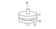
- the test apparatus 50 includes a first compression jig 51 (a member corresponding to the processing structure 20 such as a catalyst carrier) which is a disc (diameter 100 mm, thickness 30 mm) made of Inconel (registered trademark), and the first And a second compression jig 52 (a member corresponding to the casing 40), which is an Inconel (registered trademark) disk (diameter: 100 mm, thickness: 30 mm) disposed opposite to the one compression jig 51.
- a first compression jig 51 a member corresponding to the processing structure 20 such as a catalyst carrier
- a second compression jig 52 a member corresponding to the casing 40
- the first compression jig 51 and the second compression jig 52 sandwiched and held one of the two types of holding materials 10.
- the distance between the first compression jig 51 and the second compression jig 52 was adjusted to 4 mm. That is, the first holding material 10 is compressed and its bulk density is adjusted to 0.3 g / cm 3 , or the second holding material 10 is compressed and its bulk density is 0.5 g / cm 3 . It was adjusted.
- Example 1-1 when a gasoline engine is used, the metal casing expands / contracts at a temperature of 700 to 900 ° C. and a stroke amount of 0.2 mm, which corresponds to a case where the metal casing repeatedly expands and contracts at a thermal expansion coefficient of 5% A compression test was performed.
- the distance between the first compression jig 51 and the second compression jig 52 is increased by 0.2 mm. (Expansion), and then the (compression) cycle in which the distance between the first compression jig 51 and the second compression jig 52 is reduced by 0.2 mm was repeated 1000 times. During the 1000 cycles, the temperature of the first compression jig 51 and the temperature of the second compression jig 52 were maintained at 900 ° C. and 700 ° C., respectively.
- swelling in each cycle was measured as surface pressure (kPa). That is, for example, when the repulsive force N (kPa) was measured with the first compression jig 51, the N (kPa) was directly obtained as the surface pressure.
- Example 1-2 when a diesel engine is used, expansion is performed at a temperature of 240 to 300 ° C. and a stroke amount of 0.08 mm, which corresponds to a case where a metal casing repeats expansion and contraction at a thermal expansion coefficient of 2%. / A compression test was performed.
- the distance between the first jig 51 and the second jig 52 is increased by 0.08 mm (expansion)
- the cycle of reducing (compressing) the distance between the first jig 51 and the second jig 52 by 0.08 mm was repeated 1000 times.
- swelling in each cycle was measured as surface pressure (kPa). That is, for example, when the repulsive force N (kPa) was measured with the first compression jig 51, the N (kPa) was directly obtained as the surface pressure.
- the aqueous slurry is wet-formed in the same manner as described above except that the aqueous slurry does not contain alumina sol, and the basis weight is 1200 g / m 2 and the bulk density is 0.126 g / cm 3.
- the first comparative holding material in a mat shape (1200 mm ⁇ 700 mm ⁇ 9.5 mm) and a mat shape (1200 mm ⁇ 700 mm ⁇ 15.4 mm) having a basis weight of 2000 g / m 2 and a bulk density of 0.130 g / cm 3 ) Second comparative holding material. Then, the surface pressure of the comparative holding material was evaluated in the same manner as described above except that this comparative holding material was used instead of the holding material 10 described above.
- FIG. 6 shows the result of evaluating the surface pressure. That is, FIG. 6 shows a holding material 10 containing alumina sol (“6 parts by mass added”) and a comparative holding material not containing alumina sol (“no addition”) in Example 1-1 and Example 1-2, respectively. However, when the initial bulk density (“initial density”) is 0.3 g / cm 3 or 0.5 g / cm 3 , the surface shown at the time of expansion and compression of 1 cycle, 100 cycles, 500 cycles and 1000 cycles The pressure (kPa) is shown.
- initial density initial bulk density
- Example 1-1 and Example 1-2 holding containing alumina sol at all points of expansion, compression, and 1 cycle, 100 cycles, 500 cycles, and 1000 cycles
- the surface pressure of the material 10 was significantly higher than that of the comparative holding material containing no alumina sol. Further, the high surface pressure of the holding material 10 containing this alumina sol was maintained over 1 to 1000 cycles.
- the silica fiber holding material 10 containing the alumina sol was manufactured in the same manner as in the case of the first holding material 10 in Example 1 described above. .
- the silica fiber contains 10 parts by mass or 15 parts by mass of alumina sol in terms of solid content, and the basis weight is 1200 g / m. 2.
- the surface pressure was evaluated in the same manner as in Example 1 described above. That is, as shown in FIG. 5, the first compression jig 51 and the second compression jig 52 were held by sandwiching one of the two types of holding materials 10 having different alumina sol contents. At this time, the holding material 10 was compressed by adjusting the distance between the first compression jig 51 and the second compression jig 52 to 4 mm, and the bulk density was adjusted to 0.3 g / cm 3 .
- the expansion / compression test is performed 1000 cycles at a temperature of 700 to 900 ° C and a stroke amount of 0.2 mm, which corresponds to the case where the metal casing repeats expansion and contraction at a thermal expansion coefficient of 5%. went.
- FIG. 7 shows the result of evaluating the surface pressure. That is, in FIG. 7, the holding
- FIG. 7 shows the results of the holding material 10 containing 6 parts by mass of the alumina sol measured in Example 1-1 and the comparative holding material not containing the alumina sol (initial density in Example 1-1 shown in FIG. 6). The result at 1000 cycles in the case of 0.3 g / cm 3 is also shown.
- both the surface pressure of the holding material 10 containing 10 parts by mass of alumina sol and the surface pressure of the holding material 10 containing 15 parts by mass of alumina sol are significantly higher than those of the comparative holding material containing no alumina sol. It was.
- a holding material made of alumina fibers containing alumina sol was produced in the same manner as in Example 1 and Example 2, and the surface pressure of the holding material was evaluated. .
- Example 1 and Example 2 that is, by wet molding similar to Example 1 and Example 2 described above, 6 parts by mass, 10 parts by mass or 100 parts by mass in terms of solid content with respect to 100 parts by mass of alumina fibers (96% by mass alumina, 4% by mass silica)
- a mat-shaped holding material (1200 mm ⁇ 700 mm ⁇ 9.2 mm) containing 15 parts by mass of alumina sol, having a basis weight of 1200 g / m 2 and a bulk density of 0.130 g / cm 3 was produced.
- a holding material made of alumina fiber not containing alumina sol was produced in the same manner except that it did not contain alumina sol.
- the surface pressure was evaluated in the same manner as in Example 1 and Example 2 described above.
- FIG. 8 shows the results of evaluating the surface pressure. As shown in FIG. 8, the surface pressure of the holding material made of alumina fiber containing alumina sol was almost the same as that of the holding material made of alumina fiber not containing alumina sol.
Landscapes
- Chemical & Material Sciences (AREA)
- Engineering & Computer Science (AREA)
- Chemical Kinetics & Catalysis (AREA)
- Mechanical Engineering (AREA)
- General Engineering & Computer Science (AREA)
- Combustion & Propulsion (AREA)
- Health & Medical Sciences (AREA)
- Toxicology (AREA)
- Ceramic Engineering (AREA)
- Organic Chemistry (AREA)
- Materials Engineering (AREA)
- Manufacturing & Machinery (AREA)
- Geochemistry & Mineralogy (AREA)
- General Chemical & Material Sciences (AREA)
- Life Sciences & Earth Sciences (AREA)
- Inorganic Chemistry (AREA)
- Structural Engineering (AREA)
- Exhaust Gas After Treatment (AREA)
- Exhaust Gas Treatment By Means Of Catalyst (AREA)
- Paper (AREA)
- Catalysts (AREA)
Priority Applications (3)
| Application Number | Priority Date | Filing Date | Title |
|---|---|---|---|
| EP12866740.9A EP2808511B1 (fr) | 2012-01-23 | 2012-11-14 | Matériau de support pour dispositif de traitement de gaz, dispositif de traitement de gaz et procédés de production associés |
| CN201280067953.9A CN104066947B (zh) | 2012-01-23 | 2012-11-14 | 气体处理装置用保持材料、气体处理装置及它们的制造方法 |
| US14/374,066 US9796634B2 (en) | 2012-01-23 | 2012-11-14 | Holding material for gas treatment device, gas treatment device, and production processes therefor |
Applications Claiming Priority (2)
| Application Number | Priority Date | Filing Date | Title |
|---|---|---|---|
| JP2012-011304 | 2012-01-23 | ||
| JP2012011304A JP6012968B2 (ja) | 2012-01-23 | 2012-01-23 | 気体処理装置用保持材、気体処理装置及びこれらの製造方法 |
Publications (1)
| Publication Number | Publication Date |
|---|---|
| WO2013111428A1 true WO2013111428A1 (fr) | 2013-08-01 |
Family
ID=48873170
Family Applications (1)
| Application Number | Title | Priority Date | Filing Date |
|---|---|---|---|
| PCT/JP2012/079564 Ceased WO2013111428A1 (fr) | 2012-01-23 | 2012-11-14 | Matériau de support pour dispositif de traitement de gaz, dispositif de traitement de gaz et procédés de production associés |
Country Status (5)
| Country | Link |
|---|---|
| US (1) | US9796634B2 (fr) |
| EP (1) | EP2808511B1 (fr) |
| JP (1) | JP6012968B2 (fr) |
| CN (1) | CN104066947B (fr) |
| WO (1) | WO2013111428A1 (fr) |
Cited By (1)
| Publication number | Priority date | Publication date | Assignee | Title |
|---|---|---|---|---|
| WO2022210181A1 (fr) * | 2021-03-31 | 2022-10-06 | イビデン株式会社 | Mat, dispositif de purification de gaz d'échappement et procédé de fabrication de mat |
Families Citing this family (6)
| Publication number | Priority date | Publication date | Assignee | Title |
|---|---|---|---|---|
| JP6386223B2 (ja) * | 2013-12-05 | 2018-09-05 | イビデン株式会社 | シート状部材の裁断方法及び排ガス浄化装置の製造方法 |
| DE102014221828A1 (de) * | 2014-10-27 | 2016-04-28 | Eberspächer Exhaust Technology GmbH & Co. KG | Abgasbehandlungsanordnung, insbesondere für einen Abgasströmungsweg einer Brennkraftmaschine und Verfahren zur Herstellung einer Abgasbehandlungsanordnung |
| JP6506830B2 (ja) | 2015-02-25 | 2019-04-24 | ニチアス株式会社 | 保持材、その製造方法及びそれを用いた気体処理装置 |
| PL3141648T3 (pl) | 2015-09-08 | 2018-12-31 | 3M Innovative Properties Company | Element mocujący do opakowania oraz montaż elementu kontroli zanieczyszczeń |
| CN105649716A (zh) * | 2015-12-20 | 2016-06-08 | 黔东南州龙达再生能源开发有限责任公司 | 汽车尾气过滤装置 |
| JP6486328B2 (ja) * | 2016-12-26 | 2019-03-20 | ニチアス株式会社 | 排気ガス処理装置用保持材および排気ガス処理装置 |
Citations (3)
| Publication number | Priority date | Publication date | Assignee | Title |
|---|---|---|---|---|
| JPH11509509A (ja) * | 1995-06-30 | 1999-08-24 | ミネソタ・マイニング・アンド・マニュファクチャリング・カンパニー | ガラス繊維を有する膨張シート材 |
| JP2005194904A (ja) | 2004-01-05 | 2005-07-21 | Ge Techno Kk | 触媒用保持マット及びその製造工程に用いられる成形装置。 |
| JP2011038529A (ja) * | 2004-06-29 | 2011-02-24 | Unifrax I Llc | 排気ガス処理装置及びその製造方法 |
Family Cites Families (11)
| Publication number | Priority date | Publication date | Assignee | Title |
|---|---|---|---|---|
| US5032441A (en) | 1989-05-01 | 1991-07-16 | The Carborundum Company | Intumescent conforming mounting pad |
| US5290522A (en) * | 1993-01-07 | 1994-03-01 | Minnesota Mining And Manufacturing Company | Catalytic converter mounting mat |
| US6231818B1 (en) * | 1998-12-08 | 2001-05-15 | Unifrax Corporation | Amorphous non-intumescent inorganic fiber mat for low temperature exhaust gas treatment devices |
| US7033412B2 (en) | 2002-09-30 | 2006-04-25 | Unifrax Corporation | Exhaust gas treatment device and method for making the same |
| JP5112029B2 (ja) * | 2007-01-26 | 2013-01-09 | イビデン株式会社 | シート材およびその製造方法、排気ガス処理装置およびその製造方法、ならびに消音装置 |
| EP1953357B1 (fr) | 2007-01-26 | 2009-08-26 | Ibiden Co., Ltd. | Mat de support et son procédé de fabrication, appareil de traitement de gaz d'échappement et son procédé de fabrication et dispositif silencieux |
| EP2487342B1 (fr) * | 2007-06-13 | 2018-04-18 | 3M Innovative Properties Company | Matériau de montage résistant à l'érosion et son procédé de fabrication et d'utilisation |
| CN101715508B (zh) * | 2008-07-10 | 2012-07-25 | 揖斐电株式会社 | 保持密封材料、废气净化装置及废气净化装置的制造方法 |
| JP5288115B2 (ja) | 2008-12-10 | 2013-09-11 | ニチアス株式会社 | 触媒コンバーター及び触媒コンバーター用保持材の製造方法 |
| EP2388453B1 (fr) * | 2010-05-17 | 2012-10-24 | Ibiden Co., Ltd. | Matériau de scellage de fixation, procédé d'enroulement du matériau de scellage de fixation et appareil de purification de gaz d'échappement |
| US20110311404A1 (en) * | 2010-06-16 | 2011-12-22 | Creedon Matthew J | Thermally Stable Inorganic Fibers For Exhaust Gas Treatment Device Insulating Mat |
-
2012
- 2012-01-23 JP JP2012011304A patent/JP6012968B2/ja active Active
- 2012-11-14 WO PCT/JP2012/079564 patent/WO2013111428A1/fr not_active Ceased
- 2012-11-14 US US14/374,066 patent/US9796634B2/en not_active Expired - Fee Related
- 2012-11-14 EP EP12866740.9A patent/EP2808511B1/fr not_active Not-in-force
- 2012-11-14 CN CN201280067953.9A patent/CN104066947B/zh not_active Expired - Fee Related
Patent Citations (3)
| Publication number | Priority date | Publication date | Assignee | Title |
|---|---|---|---|---|
| JPH11509509A (ja) * | 1995-06-30 | 1999-08-24 | ミネソタ・マイニング・アンド・マニュファクチャリング・カンパニー | ガラス繊維を有する膨張シート材 |
| JP2005194904A (ja) | 2004-01-05 | 2005-07-21 | Ge Techno Kk | 触媒用保持マット及びその製造工程に用いられる成形装置。 |
| JP2011038529A (ja) * | 2004-06-29 | 2011-02-24 | Unifrax I Llc | 排気ガス処理装置及びその製造方法 |
Non-Patent Citations (1)
| Title |
|---|
| See also references of EP2808511A4 |
Cited By (4)
| Publication number | Priority date | Publication date | Assignee | Title |
|---|---|---|---|---|
| WO2022210181A1 (fr) * | 2021-03-31 | 2022-10-06 | イビデン株式会社 | Mat, dispositif de purification de gaz d'échappement et procédé de fabrication de mat |
| JP2022156707A (ja) * | 2021-03-31 | 2022-10-14 | イビデン株式会社 | マット材、排ガス浄化装置及びマット材の製造方法 |
| JP7432552B2 (ja) | 2021-03-31 | 2024-02-16 | イビデン株式会社 | マット材、排ガス浄化装置及びマット材の製造方法 |
| US12031471B2 (en) | 2021-03-31 | 2024-07-09 | Ibiden Co., Ltd. | Matting, exhaust gas purification device, and method for manufacturing matting |
Also Published As
| Publication number | Publication date |
|---|---|
| JP6012968B2 (ja) | 2016-10-25 |
| US9796634B2 (en) | 2017-10-24 |
| EP2808511A1 (fr) | 2014-12-03 |
| US20150033714A1 (en) | 2015-02-05 |
| EP2808511A4 (fr) | 2015-12-16 |
| JP2013148072A (ja) | 2013-08-01 |
| CN104066947B (zh) | 2017-12-01 |
| CN104066947A (zh) | 2014-09-24 |
| EP2808511B1 (fr) | 2021-03-17 |
Similar Documents
| Publication | Publication Date | Title |
|---|---|---|
| JP6012968B2 (ja) | 気体処理装置用保持材、気体処理装置及びこれらの製造方法 | |
| KR101232957B1 (ko) | 촉매 컨버터용 보유 시일재 및 촉매 컨버터 | |
| JP2002349255A (ja) | 触媒コンバータ用保持シール材及びその製造方法、触媒コンバータ | |
| JP5912931B2 (ja) | 気体処理装置用保持材、気体処理装置及びこれらの製造方法 | |
| JP2011231774A (ja) | 触媒コンバータ用保持シール材の製造方法 | |
| US20190308139A1 (en) | Holding material for exhaust gas treatment apparatus and exhaust gas treatment apparatus | |
| JP6017833B2 (ja) | 気体処理装置及び気体処理方法 | |
| JP2013155750A (ja) | 触媒コンバータ用保持シール材 | |
| WO2011061842A1 (fr) | Procédé de production d'une structure en nid d'abeille | |
| JP2002276350A (ja) | 触媒コンバータ用保持シール材及びその製造方法、セラミック繊維集合体、セラミック繊維 | |
| JP2002348740A (ja) | アルミナーシリカ系繊維及びその製造方法、触媒コンバータ用保持シール材 | |
| JP6063799B2 (ja) | 気体処理装置用保持材、気体処理装置及びその製造方法 | |
| JP2011125845A (ja) | ハニカム構造体の製造方法 | |
| CN102481750B (zh) | 管状、连续、无缝、可压缩、有弹性的安装制品以及包括所述安装制品的污染控制装置 | |
| WO2014156104A1 (fr) | Matière de rétention pour dispositif de traitement de gaz | |
| JP2019152208A (ja) | 気体処理装置用保持材 | |
| KR20180048977A (ko) | 오염 제어 요소를 랩핑 및 장착하는 장착 부재 | |
| JP2015078702A (ja) | 触媒コンバータ用保持シール材の製造方法 | |
| JPH0759885B2 (ja) | 耐熱膨張性部材 |
Legal Events
| Date | Code | Title | Description |
|---|---|---|---|
| 121 | Ep: the epo has been informed by wipo that ep was designated in this application |
Ref document number: 12866740 Country of ref document: EP Kind code of ref document: A1 |
|
| WWE | Wipo information: entry into national phase |
Ref document number: 2012866740 Country of ref document: EP |
|
| NENP | Non-entry into the national phase |
Ref country code: DE |
|
| WWE | Wipo information: entry into national phase |
Ref document number: 14374066 Country of ref document: US |