WO2013111464A1 - Dispositif de commande de déplacement - Google Patents
Dispositif de commande de déplacement Download PDFInfo
- Publication number
- WO2013111464A1 WO2013111464A1 PCT/JP2012/082107 JP2012082107W WO2013111464A1 WO 2013111464 A1 WO2013111464 A1 WO 2013111464A1 JP 2012082107 W JP2012082107 W JP 2012082107W WO 2013111464 A1 WO2013111464 A1 WO 2013111464A1
- Authority
- WO
- WIPO (PCT)
- Prior art keywords
- travel
- control device
- hybrid vehicle
- ecu
- battery
- Prior art date
- Legal status (The legal status is an assumption and is not a legal conclusion. Google has not performed a legal analysis and makes no representation as to the accuracy of the status listed.)
- Ceased
Links
Images


Classifications
-
- B—PERFORMING OPERATIONS; TRANSPORTING
- B60—VEHICLES IN GENERAL
- B60L—PROPULSION OF ELECTRICALLY-PROPELLED VEHICLES; SUPPLYING ELECTRIC POWER FOR AUXILIARY EQUIPMENT OF ELECTRICALLY-PROPELLED VEHICLES; ELECTRODYNAMIC BRAKE SYSTEMS FOR VEHICLES IN GENERAL; MAGNETIC SUSPENSION OR LEVITATION FOR VEHICLES; MONITORING OPERATING VARIABLES OF ELECTRICALLY-PROPELLED VEHICLES; ELECTRIC SAFETY DEVICES FOR ELECTRICALLY-PROPELLED VEHICLES
- B60L58/00—Methods or circuit arrangements for monitoring or controlling batteries or fuel cells, specially adapted for electric vehicles
- B60L58/10—Methods or circuit arrangements for monitoring or controlling batteries or fuel cells, specially adapted for electric vehicles for monitoring or controlling batteries
- B60L58/12—Methods or circuit arrangements for monitoring or controlling batteries or fuel cells, specially adapted for electric vehicles for monitoring or controlling batteries responding to state of charge [SoC]
- B60L58/13—Maintaining the SoC within a determined range
-
- B—PERFORMING OPERATIONS; TRANSPORTING
- B60—VEHICLES IN GENERAL
- B60W—CONJOINT CONTROL OF VEHICLE SUB-UNITS OF DIFFERENT TYPE OR DIFFERENT FUNCTION; CONTROL SYSTEMS SPECIALLY ADAPTED FOR HYBRID VEHICLES; ROAD VEHICLE DRIVE CONTROL SYSTEMS FOR PURPOSES NOT RELATED TO THE CONTROL OF A PARTICULAR SUB-UNIT
- B60W10/00—Conjoint control of vehicle sub-units of different type or different function
- B60W10/04—Conjoint control of vehicle sub-units of different type or different function including control of propulsion units
- B60W10/06—Conjoint control of vehicle sub-units of different type or different function including control of propulsion units including control of combustion engines
-
- B—PERFORMING OPERATIONS; TRANSPORTING
- B60—VEHICLES IN GENERAL
- B60W—CONJOINT CONTROL OF VEHICLE SUB-UNITS OF DIFFERENT TYPE OR DIFFERENT FUNCTION; CONTROL SYSTEMS SPECIALLY ADAPTED FOR HYBRID VEHICLES; ROAD VEHICLE DRIVE CONTROL SYSTEMS FOR PURPOSES NOT RELATED TO THE CONTROL OF A PARTICULAR SUB-UNIT
- B60W10/00—Conjoint control of vehicle sub-units of different type or different function
- B60W10/04—Conjoint control of vehicle sub-units of different type or different function including control of propulsion units
- B60W10/08—Conjoint control of vehicle sub-units of different type or different function including control of propulsion units including control of electric propulsion units, e.g. motors or generators
-
- B—PERFORMING OPERATIONS; TRANSPORTING
- B60—VEHICLES IN GENERAL
- B60W—CONJOINT CONTROL OF VEHICLE SUB-UNITS OF DIFFERENT TYPE OR DIFFERENT FUNCTION; CONTROL SYSTEMS SPECIALLY ADAPTED FOR HYBRID VEHICLES; ROAD VEHICLE DRIVE CONTROL SYSTEMS FOR PURPOSES NOT RELATED TO THE CONTROL OF A PARTICULAR SUB-UNIT
- B60W10/00—Conjoint control of vehicle sub-units of different type or different function
- B60W10/24—Conjoint control of vehicle sub-units of different type or different function including control of energy storage means
- B60W10/26—Conjoint control of vehicle sub-units of different type or different function including control of energy storage means for electrical energy, e.g. batteries or capacitors
-
- B—PERFORMING OPERATIONS; TRANSPORTING
- B60—VEHICLES IN GENERAL
- B60W—CONJOINT CONTROL OF VEHICLE SUB-UNITS OF DIFFERENT TYPE OR DIFFERENT FUNCTION; CONTROL SYSTEMS SPECIALLY ADAPTED FOR HYBRID VEHICLES; ROAD VEHICLE DRIVE CONTROL SYSTEMS FOR PURPOSES NOT RELATED TO THE CONTROL OF A PARTICULAR SUB-UNIT
- B60W20/00—Control systems specially adapted for hybrid vehicles
- B60W20/10—Controlling the power contribution of each of the prime movers to meet required power demand
- B60W20/12—Controlling the power contribution of each of the prime movers to meet required power demand using control strategies taking into account route information
-
- B—PERFORMING OPERATIONS; TRANSPORTING
- B60—VEHICLES IN GENERAL
- B60W—CONJOINT CONTROL OF VEHICLE SUB-UNITS OF DIFFERENT TYPE OR DIFFERENT FUNCTION; CONTROL SYSTEMS SPECIALLY ADAPTED FOR HYBRID VEHICLES; ROAD VEHICLE DRIVE CONTROL SYSTEMS FOR PURPOSES NOT RELATED TO THE CONTROL OF A PARTICULAR SUB-UNIT
- B60W20/00—Control systems specially adapted for hybrid vehicles
- B60W20/10—Controlling the power contribution of each of the prime movers to meet required power demand
- B60W20/13—Controlling the power contribution of each of the prime movers to meet required power demand in order to stay within battery power input or output limits; in order to prevent overcharging or battery depletion
-
- B—PERFORMING OPERATIONS; TRANSPORTING
- B60—VEHICLES IN GENERAL
- B60W—CONJOINT CONTROL OF VEHICLE SUB-UNITS OF DIFFERENT TYPE OR DIFFERENT FUNCTION; CONTROL SYSTEMS SPECIALLY ADAPTED FOR HYBRID VEHICLES; ROAD VEHICLE DRIVE CONTROL SYSTEMS FOR PURPOSES NOT RELATED TO THE CONTROL OF A PARTICULAR SUB-UNIT
- B60W2510/00—Input parameters relating to a particular sub-units
- B60W2510/24—Energy storage means
- B60W2510/242—Energy storage means for electrical energy
- B60W2510/244—Charge state
-
- B—PERFORMING OPERATIONS; TRANSPORTING
- B60—VEHICLES IN GENERAL
- B60W—CONJOINT CONTROL OF VEHICLE SUB-UNITS OF DIFFERENT TYPE OR DIFFERENT FUNCTION; CONTROL SYSTEMS SPECIALLY ADAPTED FOR HYBRID VEHICLES; ROAD VEHICLE DRIVE CONTROL SYSTEMS FOR PURPOSES NOT RELATED TO THE CONTROL OF A PARTICULAR SUB-UNIT
- B60W2552/00—Input parameters relating to infrastructure
- B60W2552/15—Road slope, i.e. the inclination of a road segment in the longitudinal direction
-
- Y—GENERAL TAGGING OF NEW TECHNOLOGICAL DEVELOPMENTS; GENERAL TAGGING OF CROSS-SECTIONAL TECHNOLOGIES SPANNING OVER SEVERAL SECTIONS OF THE IPC; TECHNICAL SUBJECTS COVERED BY FORMER USPC CROSS-REFERENCE ART COLLECTIONS [XRACs] AND DIGESTS
- Y02—TECHNOLOGIES OR APPLICATIONS FOR MITIGATION OR ADAPTATION AGAINST CLIMATE CHANGE
- Y02T—CLIMATE CHANGE MITIGATION TECHNOLOGIES RELATED TO TRANSPORTATION
- Y02T10/00—Road transport of goods or passengers
- Y02T10/60—Other road transportation technologies with climate change mitigation effect
- Y02T10/62—Hybrid vehicles
-
- Y—GENERAL TAGGING OF NEW TECHNOLOGICAL DEVELOPMENTS; GENERAL TAGGING OF CROSS-SECTIONAL TECHNOLOGIES SPANNING OVER SEVERAL SECTIONS OF THE IPC; TECHNICAL SUBJECTS COVERED BY FORMER USPC CROSS-REFERENCE ART COLLECTIONS [XRACs] AND DIGESTS
- Y02—TECHNOLOGIES OR APPLICATIONS FOR MITIGATION OR ADAPTATION AGAINST CLIMATE CHANGE
- Y02T—CLIMATE CHANGE MITIGATION TECHNOLOGIES RELATED TO TRANSPORTATION
- Y02T10/00—Road transport of goods or passengers
- Y02T10/60—Other road transportation technologies with climate change mitigation effect
- Y02T10/70—Energy storage systems for electromobility, e.g. batteries
Definitions
- the present invention relates to a travel control device.
- a travel control device that is mounted on a vehicle and controls the travel of the vehicle.
- a travel control device that is mounted on a vehicle and controls the travel of the vehicle.
- Patent Document 1 in a hybrid vehicle including a motor and an engine as a vehicle drive source, depending on driving conditions, the vehicle travels only by the driving force of the motor, or at least by the driving force of the engine, A travel control device for a hybrid vehicle that selects is described.
- a hybrid vehicle travel control apparatus disclosed in Patent Document 1 described above and the like has a state-of-charge of a battery (referred to as a secondary battery) that supplies electric power to a motor.
- a battery referred to as a secondary battery
- SOC falls under one of a predetermined first predetermined value and a high load state that requires a relatively large driving torque, such as high-speed traveling or uphill traveling. Determine whether.
- the travel control device determines that the SOC falls into one of a state where the SOC is lower than a predetermined first predetermined value and a high load state where a relatively large driving torque is required, such as high-speed traveling or uphill traveling. Then, it is selected to travel at least by the travel driving force of the engine.
- the travel control device may be in any one of a state where the SOC is lower than a predetermined first predetermined value and a high load state where a relatively large driving torque is required, such as high-speed traveling or uphill traveling. If it is determined that this is not the case, the vehicle is selected to travel only by the driving force of the motor.
- the present invention has been made in view of the above circumstances, and an object of the present invention is to provide a travel control device that can further reduce the running cost of the entire hybrid vehicle.
- the present invention provides a battery that can be charged with electric power from an external power source, a motor that generates a driving force using the electric power of the battery, and an engine that generates a driving force.
- a travel control device that selects an EV mode that travels only by the travel driving force of the motor and an HV mode that travels by at least the travel drive force of the engine.
- the estimated charging time capable of charging the battery is estimated. When the estimated expected charging time is long, the EV mode is reached until the destination is reached, compared to when the estimated charging time is short.
- the EV mode and the HV mode are selected so as to increase the frequency of.
- the travel control device stores an actual charging time required for the battery to be actually charged from the external power source for each stop position of the hybrid vehicle, and the stored stop position for each of the stored stop positions. It is preferable to estimate the expected charging time based on the actual charging time.
- the travel control device determines the frequency of the HV mode at the time of high load until the destination is reached, compared to when the estimated charging time is short. It is preferable to select the EV mode and the HV mode so as to suppress them.
- the traveling control device When the estimated charging time during which the battery at the estimated destination can be charged is long, the traveling control device according to the present invention is in the EV mode in which the vehicle travels only by the traveling driving force of the motor until the destination is reached. Increase frequency. Therefore, it is possible to suppress the deterioration of the fuel consumption due to the driving of the engine and to further reduce the running cost as the whole hybrid vehicle.
- FIG. 1 is a schematic configuration diagram of a hybrid vehicle including a travel control device according to an embodiment.
- FIG. 2 is a schematic configuration diagram of an ECU and a navigation device of the travel control device according to the embodiment.
- FIG. 3 is a flowchart for selecting a travel plan of the ECU of the travel control apparatus according to the embodiment.
- FIG. 4 is a flowchart illustrating a second travel plan of the ECU of the travel control apparatus according to the embodiment.
- FIG. 5 is a flowchart showing a first travel plan of the ECU of the travel control apparatus according to the embodiment.
- FIG. 6 is a diagram for explaining the change in the SOC with respect to the travel distance of the comparative example and the present invention.
- FIG. 1 is a schematic configuration diagram of a hybrid vehicle including a travel control device according to an embodiment.
- FIG. 2 is a schematic configuration diagram of an ECU and a navigation device of the travel control device according to the embodiment.
- FIG. 3 is a flowchart for selecting a
- FIG. 7 is a flowchart for selecting a travel plan of the ECU of the travel control apparatus according to the modification according to the embodiment.
- FIG. 8 is an explanatory diagram illustrating a map for setting the ratio of the first travel plan of the drive switching unit of the ECU of the travel control apparatus according to the modification according to the embodiment.
- FIG. 9 is a flowchart for selecting a travel plan of the ECU of the travel control apparatus according to the first disclosure.
- FIG. 10 is a flowchart for selecting a travel plan of the ECU of the travel control apparatus according to the second disclosed example.
- FIG. 11 is a flowchart for selecting a travel plan of the ECU of the travel control apparatus according to the third disclosure.
- FIG. 1 is a schematic configuration diagram of a hybrid vehicle including a travel control device according to the embodiment
- FIG. 2 is a schematic configuration diagram of an ECU and a navigation device of the travel control device according to the embodiment.
- the travel control device 1 according to the present embodiment is a so-called hybrid vehicle 2 that combines an engine 5 and an MG 6 as a motor to serve as a travel drive source for rotationally driving drive wheels. Installed.
- the travel control device 1 includes an ECU (Electronic Control Unit) 50.
- the travel control device 1 selects the travel plan of the hybrid vehicle 2 by the ECU 50 controlling the engine 5, the MG 6 and a transmission 7 described later according to the situation.
- the travel control device 1 of the present embodiment selects a travel plan based on the expected charging time during which the battery 9 at the destination can be charged. Thereby, the traveling control device 1 is configured to allow further reduction in running cost of the hybrid vehicle 2 as a whole.
- the travel control device 1 of the present embodiment includes a first travel plan that prohibits an HV mode in a high load state among an EV mode and an HV mode, which will be described later, and a second travel plan that allows an HV mode in a high load state. And select.
- the hybrid vehicle 2 includes an engine 5 as an internal combustion engine, a motor generator (hereinafter referred to as “MG”) 6, a transmission 7, a brake device 8, a battery 9, and the like.
- the hybrid vehicle 2 includes a vehicle speed sensor 10, an accelerator sensor 11, a brake sensor 12, a navigation device 13, and the like.
- the engine 5 causes the driving force to act on the wheels of the hybrid vehicle 2 in response to an acceleration request operation by the driver, for example, an accelerator pedal depression operation.
- the engine 5 consumes fuel and generates an engine torque as an engine torque as a driving force to be applied to the driving wheels of the hybrid vehicle 2.
- the engine 5 is a heat engine that outputs thermal energy generated by burning fuel in the form of mechanical energy such as torque, and examples thereof include a gasoline engine, a diesel engine, and an LPG engine.
- the engine 5 includes, for example, a fuel injection device, an ignition device, a throttle valve device, and the like (not shown). These devices are electrically connected to the ECU 50 and controlled by the ECU 50.
- the output torque of the engine 5 is controlled by the ECU 50.
- the driving force generated by the engine 5 may be used for power generation in the MG 6.
- MG6 causes the driving force to act on the wheels of the hybrid vehicle 2 in response to an acceleration request operation by the driver, for example, an accelerator pedal depression operation.
- the MG 6 converts electric energy into mechanical power and generates motor torque as travel driving force that acts on the drive wheels of the hybrid vehicle 2.
- MG6 is what is called a rotary electric machine provided with the stator which is a stator, and the rotor which is a rotor.
- the MG 6 is an electric motor that converts electric energy into mechanical power and outputs it, and also a generator that converts mechanical power into electric energy and recovers it.
- the MG 6 is driven by supplying electric power, functions as an electric motor that converts electric energy into mechanical energy and outputs it (power running function), and functions as a generator that converts mechanical energy into electric energy (regenerative function).
- the MG 6 is electrically connected to the ECU 50 through an inverter or the like that converts direct current and alternating current, and is controlled by the ECU 50.
- the output torque and power generation amount of the MG 6 are controlled by the ECU 50 via an inverter.
- the transmission 7 is a power transmission device that shifts the rotational driving force of the engine 5 and the MG 6 and transmits it to the driving wheel side of the hybrid vehicle 2.
- the transmission 7 may be a so-called manual transmission (MT), a stepped automatic transmission (AT), a continuously variable automatic transmission (CVT), a multimode manual transmission (MMT), a sequential manual transmission (SMT). ), A so-called automatic transmission such as a dual clutch transmission (DCT).
- MT manual transmission
- AT continuously variable automatic transmission
- MMT multimode manual transmission
- SMT sequential manual transmission
- DCT dual clutch transmission
- the transmission 7 is controlled by the ECU 50 with a transmission actuator or the like electrically connected to the ECU 50.
- the brake device 8 applies a braking force to the wheels of the hybrid vehicle 2 in response to a braking request operation by the driver, for example, a depression operation of a brake pedal.
- the brake device 8 applies a braking force to a wheel rotatably supported by the vehicle body of the hybrid vehicle 2 by generating a predetermined friction force (friction resistance force) between friction elements such as a brake pad and a brake disk, for example. To do.
- the brake device 8 can generate a braking force on the ground contact surface with the road surface of the wheel of the hybrid vehicle 2 to brake the hybrid vehicle 2.
- the brake device 8 is controlled by the ECU 50 with a brake actuator or the like electrically connected to the ECU 50.
- the battery 9 is a power storage device capable of storing electric power (electric storage) and discharging the stored electric power.
- the battery 9 is electrically connected to the ECU 50 and outputs signals related to various information to the ECU 50.
- the battery 9 according to the present embodiment detects a state of charge (hereinafter referred to as SOC) and outputs the detected result to the ECU 50.
- the battery 9 is connected to the MG 6 via an inverter (not shown). Further, the battery 9 is connected to a connector 15 connected to an external power source 14 such as a household power source via an inverter. The battery 9 is supplied with power from an external power source 14 such as a household power source via a connector 15 and an inverter. For this reason, the battery 9 can be charged with electric power from the external power supply 14 by connecting the external power supply 14 to the connector 15.
- the external power supply 14 as used in the field of this invention means the power supply which can charge the battery 9 via the connector 15 grade
- the MG 6 When the MG 6 functions as an electric motor, the electric power stored in the battery 9 is supplied via an inverter, and the supplied electric power is converted into a driving force for driving the hybrid vehicle 2 and output. Moreover, when MG6 functions as a generator, it generates electric power with the input driving force and charges the battery 9 with the generated electric power via an inverter. At this time, the MG 6 can brake the rotation of the rotor (regenerative braking) by the rotational resistance generated in the rotor. As a result, during regenerative braking, the MG 6 can generate a motor regenerative torque, which is a negative motor torque, in the rotor by regenerating electric power.
- a motor regenerative torque which is a negative motor torque
- the MG 6 can apply a braking force to the drive wheels of the hybrid vehicle 2. It can. That is, in the hybrid vehicle 2, mechanical power is input from the drive wheels to the MG 6, and the MG 6 generates electric power by regeneration, whereby the kinetic energy of the hybrid vehicle 2 can be recovered as electric energy. And the hybrid vehicle 2 can perform regenerative braking by MG6 by transmitting the mechanical power (negative motor torque) which arises in the rotor of MG6 in connection with this to a driving wheel. In this case, in the hybrid vehicle 2, when the regeneration amount (power generation amount) by the MG 6 is relatively small, the generated braking force is relatively small, and the deceleration acting on the hybrid vehicle 2 is relatively small. Become. On the other hand, in the hybrid vehicle 2, when the regeneration amount (power generation amount) by the MG 6 is relatively increased, the generated braking force is relatively increased, and the deceleration acting on the hybrid vehicle 2 is relatively increased. .
- the vehicle speed sensor 10, the accelerator sensor 11, and the brake sensor 12 are input to the hybrid vehicle 2 by the driving state of the hybrid vehicle 2 (driver input), that is, state quantities and physical quantities related to the actual operation of the hybrid vehicle 2 by the driver.
- driver input that is, state quantities and physical quantities related to the actual operation of the hybrid vehicle 2 by the driver.
- vehicle speed detects the vehicle speed of the hybrid vehicle 2 (hereinafter sometimes referred to as “vehicle speed”).
- the accelerator sensor 11 detects an accelerator opening that is an operation amount (depression amount) of an accelerator pedal by a driver.
- the brake sensor 12 detects an operation amount (depression amount) of the brake pedal by the driver, for example, a master cylinder pressure.
- the vehicle speed sensor 10, the accelerator sensor 11 and the brake sensor 12 are electrically connected to the ECU 50 and output detection signals to the ECU 50.
- the navigation device 13 detects the current position and obtains the position of the hybrid vehicle 2 in the map information stored in advance, calculates the travel route to the destination, and travels to the position of the hybrid vehicle 2 and the destination. It is a device that displays routes and the like.
- the navigation device 13 is an in-vehicle device mounted in the hybrid vehicle 2, and as shown in FIG. 2, a GPS (Global Positioning System, Global Positioning System) device (hereinafter referred to as “GPS”) 16 and a database 17. , Destination setting unit 18, travel route setting unit 19, display device 20, input device 21 and the like.
- GPS Global Positioning System, Global Positioning System
- the GPS device 16 is a device that detects the current position of the hybrid vehicle 2.
- the GPS device 16 receives a GPS signal output from a GPS satellite, and measures and calculates GPS information (X coordinate; X, Y coordinate; Y) that is position information of the hybrid vehicle 2 based on the received GPS signal. .
- the GPS device 16 is electrically connected to the ECU 50 and outputs a signal related to GPS information to the ECU 50.
- the database 17 stores various information.
- the database 17 stores map information including road information, various information obtained by actual traveling of the hybrid vehicle 2, learning information, and the like.
- the road information includes road gradient information, road surface state information, road shape information, restricted vehicle speed information, road curvature (curve) information, temporary stop information, stop line position information, and the like.
- Information stored in the database 17 is appropriately referred to by the ECU 50, and necessary information is read out.
- the database 17 is illustrated here as being mounted on the hybrid vehicle 2, but is not limited thereto, and is provided in an information center or the like outside the hybrid vehicle 2 via wireless communication or the like (not shown). A configuration may be employed in which necessary information is read by appropriately referring to the ECU 50.
- the database 17 of the present embodiment stores information indicating whether or not the external power source 14 capable of charging the battery 9 exists at the destination set in the destination setting unit 18 as map information. .
- the destination setting unit 18 receives information indicating the position of the destination of the hybrid vehicle 2 from an occupant or the like via the input device 21.
- the destination setting unit 18 reads information indicating the position of the destination by appropriately referring to the ECU 50.
- the information indicating the position of the destination input to the destination setting unit 18 is, for example, the information from the GPS device 16 when a predetermined time has elapsed since the input of the information indicating the position of the destination from the input device 21. Based on this, it is deleted when the destination input from the input device 21 is reached.
- the travel route setting unit 19 uses GPS information (X coordinate; X, Y coordinate; Y), which is current position information of the hybrid vehicle 2 measured and calculated by the GPS device 16, and map information stored in the database 17. Based on this, the travel route to the destination is calculated and stored. In the travel route setting unit 19, information indicating the travel route to the destination is appropriately referred to by the ECU 50 and read out.
- the display device 20 includes a display device (visual information display device), a speaker (sound output device), and the like provided in the passenger compartment of the hybrid vehicle 2.
- the display device 20 displays the position, destination, and travel route of the hybrid vehicle 2 with map information and the like.
- the input device 21 has operation buttons and the like provided in the passenger compartment of the hybrid vehicle 2. The input device 21 is used for inputting a destination and the like.
- the ECU 50 is a control unit that performs overall control of the hybrid vehicle 2 and is configured as an electronic circuit mainly including a known microcomputer including a CPU, a ROM, a RAM, and an interface, for example.
- the ECU 50 corresponds to detection results detected by the vehicle speed sensor 10, the accelerator sensor 11, and the brake sensor 12, GPS information acquired by the GPS device 16, various information stored in the database 17, drive signals of each unit, control commands, and the like.
- the electrical signal is input.
- the ECU 50 controls the engine 5, the MG 6, the transmission 7, the brake device 8, the battery 9, and the like according to these input electric signals.
- the ECU 50 executes drive control of the engine 5, drive control of the MG 6, shift control of the transmission 7, brake control of the brake device 8, and the like based on the accelerator opening, the vehicle speed, and the like.
- ECU50 implement
- the EV mode refers to a travel mode in which the hybrid vehicle 2 travels only by the travel driving force of the MG 6, and the HV mode refers to a travel mode in which the hybrid vehicle 2 travels by at least the travel drive force of the engine 5.
- the ECU 50 operates the engine 5 in the most efficient state as much as possible, while making the MG 6 that is the rotating electrical machine compensate for excess or deficiency of the driving force or engine braking force, and further reduce the energy during deceleration. By improving the fuel efficiency, the fuel efficiency will be improved.
- the ECU 50 can detect ON / OFF of an accelerator operation, which is an acceleration request operation for the hybrid vehicle 2 by the driver, and an accelerator opening based on a detection result by the accelerator sensor 11.
- the ECU 50 can detect ON / OFF of a brake operation, which is a brake request operation for the hybrid vehicle 2 by the driver, based on a detection result by the brake sensor 12, for example.
- the state where the accelerator operation by the driver is OFF is a state where the driver cancels the acceleration request operation for the hybrid vehicle 2
- the state where the accelerator operation by the driver is ON is the state where the driver is the hybrid vehicle. This is a state in which an acceleration requesting operation for 2 is being performed.
- the state where the brake operation by the driver is OFF is a state where the driver releases the braking request operation for the hybrid vehicle 2
- the state where the brake operation by the driver is ON is the state where the driver is hybrid. This is a state in which a braking request operation for the vehicle 2 is being performed.
- the ECU 50 detects the driver request power based on the accelerator opening.
- the travel control device 1 is configured by the ECU 50 described above.
- the travel control device 1 may include the navigation device 13, various sensors that detect the vehicle state, and various information acquisition units that supply surrounding information, in addition to the ECU 50.
- the ECU 50 selects the first travel plan and the second travel plan according to the situation, and selects the EV mode and the HV mode in each travel plan. Can be further reduced.
- the ECU 50 when the destination is set in the destination setting unit 18, the ECU 50 is required when traveling to the destination only in the EV mode based on the travel route calculated by the travel route setting unit 19. It is determined whether or not the electric power (corresponding to the required travel energy) is less than the current remaining capacity of the battery 9.
- the traveling control device 1 When it is determined that the traveling control device 1 is below, the external power supply 14 exists at the destination with reference to the information in the database 17 and the expected charging time at the destination is determined based on the information in the storage unit 51 described later.
- the first travel plan is selected.
- the traveling control apparatus 1 is either in the case where the required traveling energy does not fall below the current remaining capacity, the case where the external power source 14 does not exist at the destination, or the case where the estimated expected charging time is short. If there is, the second travel plan is selected.
- the ECU 50 includes a storage unit 51, a first estimation unit (corresponding to a required travel energy estimation unit) 52, a determination unit 53, and a second estimation unit (corresponding to a charging time estimation unit). ) 54 and a drive switching unit 55.
- the storage unit 51 refers to the information of the navigation device 13 and calculates the time required for the battery 9 to be actually charged from the external power source 14 (hereinafter referred to as the actual charging time) for each position where the hybrid vehicle 2 is stopped. Classify and memorize.
- the storage unit 51 appropriately accumulates and stores the actual charging time for each position where the hybrid vehicle 2 stops. Specifically, the storage unit 51 has past actual actual charging times A1, A2... An at the stopped position A where the X coordinate is x1 and the Y coordinate is y1, and the X coordinate is x2, Y. If the past actual charging time at the stopped position B where the coordinate is y2 is B1, B2,... Bn, the stopped position A and the actual charging times A1, A2,. The stored position B and the actual charging times B1, B2,... Bn are stored in association with each other.
- the first estimation unit 52 Based on the travel route calculated by the travel route setting unit 19, the first estimation unit 52 requires electric power (corresponding to the required travel energy) when traveling in the EV mode only to the destination input from the input device 21. Estimate).
- the determination unit 53 refers to the information of the destination setting unit 18 of the navigation device 13 and determines whether or not the destination is set in the destination setting unit 18. Further, the determination unit 53 determines whether or not the electric power corresponding to the required travel energy estimated by the first estimation unit 52 is less than the current remaining capacity of the battery 9. Further, the determination unit 53 refers to the information of the destination setting unit 18 of the navigation device 13 and the database 17 to determine whether or not the external power supply 14 exists at the destination.
- the second estimating unit 54 predicts the expected charging time (battery 9 from the external power supply 14) at the destination input from the input device 21.
- the time during which the hybrid vehicle 2 can be charged and the hybrid vehicle 2 is stopped is estimated.
- an average value of past actual charging time at the destination input from the input device 21 is calculated from the information stored in the storage unit 51, and the calculated average value is set as the expected charging time.
- the second estimation unit 54 calculates an average value of past charging times A1, A2,... An stored in the storage unit 51. The calculated average value is set as the expected charging time.
- the second estimation unit 54 determines a value other than the average value as long as it is a value obtained from the past actual charging times A1, A2,... An stored in the storage unit 51. It is also good.
- the default value input in advance is set as the expected charging time. It is desirable that this default value exceeds a threshold that will be described later.
- the drive switching unit 55 selects the first travel plan when the expected charging time estimated by the second estimation unit 54 exceeds a predetermined threshold. Moreover, the drive switching part 55 selects a 2nd driving
- FIGS. 3 is a flowchart for selecting a travel plan of the ECU of the travel control apparatus according to the embodiment
- FIG. 4 is a flowchart of a second travel plan of the ECU of the travel control apparatus according to the embodiment.
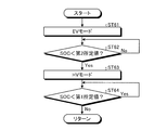
- the determination unit 53 of the ECU 50 of the travel control device 1 refers to the information from the navigation device 13 in step ST1 of FIG. It is determined whether or not the indicated information is input. That is, the determination unit 53 of the ECU 50 of the travel control device 1 determines whether or not the destination is set. If it is determined that the destination is set, the process proceeds to step ST2 and the destination is not set. If it determines, it will progress to step ST6.
- the hybrid vehicle 2 activated in the present invention refers to a state in which the hybrid vehicle 2 can immediately travel by turning on the power of the hybrid vehicle 2 and operating the accelerator pedal.
- step ST2 the first estimation unit 52 of the ECU 50 of the travel control device 1 estimates power corresponding to the required travel energy based on the travel route calculated by the travel route setting unit 19.
- step ST ⁇ b> 2 the determination unit 53 of the ECU 50 of the travel control device 1 determines whether the electric power corresponding to the estimated required travel energy is below the current remaining capacity of the battery 9.
- the process proceeds to step ST3, and when it is determined that the power is not below, Proceed to step ST7.
- step ST ⁇ b> 3 the determination unit 53 of the ECU 50 of the travel control device 1 refers to the information of the navigation device 13 and determines whether or not the external power source 14 exists at the destination set in the destination setting unit 18. . If the determination unit 53 of the ECU 50 of the travel control device 1 determines that the external power supply 14 is present, the process proceeds to step ST4. If the determination unit 53 determines that the external power supply 14 is not present, the process proceeds to step ST7.
- step ST4 the second estimation unit 54 of the ECU 50 of the travel control device 1 estimates the expected charging time at the destination based on the information stored in the storage unit 51, and proceeds to step ST5.
- step ST5 the drive switching unit 55 of the ECU 50 of the travel control device 1 determines whether or not the expected charging time estimated by the second estimation unit 54 exceeds a threshold value. If the drive switching unit 55 of the ECU 50 of the travel control device 1 determines that the threshold is exceeded, the process proceeds to step ST6, selects the first travel plan, and if it is determined that the threshold is not exceeded, the step Proceeding to ST7, the second travel plan is selected.
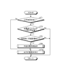
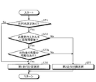
- step ST7 the drive switching unit 55 of the ECU 50 of the travel control device 1 selects the EV mode and stops or stops the engine 5 in step ST71 in FIG. Maintain and drive only MG6. Then, the drive switching unit 55 of the ECU 50 of the travel control device 1 causes the hybrid vehicle 2 to travel using only the travel driving force of the MG 6 and proceeds to step ST72. In step ST72, the drive switching unit 55 of the ECU 50 of the travel control device 1 determines whether or not the SOC of the battery 9 is below a predetermined first predetermined value.
- step ST74 the SOC of the battery 9 falls below a predetermined first predetermined value. If it is determined that there is not, the process proceeds to step ST73.
- step ST73 the drive switching unit 55 of the ECU 50 of the travel control device 1 requires a relatively large drive torque such as high-speed travel or uphill travel based on information from the transmission 7, the accelerator sensor 11, and the vehicle speed sensor 10. It is determined whether the load is high. If the drive switching unit 55 of the travel control device 1 determines that the hybrid vehicle 2 is in a high load state, the process proceeds to step ST74. If the hybrid vehicle 2 determines that the hybrid vehicle 2 is not in a high load state, the drive switching unit 55 returns to step ST72. Thus, the drive switching unit 55 of the travel control device 1 performs steps ST72 and ST73 until the SOC falls below a predetermined first predetermined value or the hybrid vehicle 2 corresponds to either a high load state. Repeatedly, the EV mode is maintained and the hybrid vehicle 2 is driven only by the driving force of the MG 6.
- step ST74 the drive switching unit 55 of the ECU 50 of the travel control device 1 selects the HV mode and drives the engine 5. Then, the drive switching unit 55 of the ECU 50 of the travel control device 1 causes the hybrid vehicle 2 to travel with at least the travel driving force of the engine 5, and the process proceeds to step ST75.
- the drive switching unit 55 of the ECU 50 of the travel control device 1 corresponds to either the state where the SOC is lower than the predetermined first predetermined value or the hybrid vehicle 2 is in the high load state. Then, it progresses to step ST74, HV mode is selected, and the hybrid vehicle 2 is drive
- step ST74 the drive switching unit 55 of the ECU 50 of the travel control device 1 operates the engine 5 in the most efficient state possible, while the transmission 7, the accelerator sensor 11, the brake sensor 12, and the vehicle speed sensor 10 are operated. Based on the information from MG6, the MG6 compensates for excess or deficiency of the driving force or engine braking force.
- the drive switching unit 55 of the ECU 50 of the travel control device 1 causes the MG 6 to perform regenerative braking to apply braking force to the driving wheels of the hybrid vehicle 2 during deceleration, and the battery 9 is connected to the power generated by the MG 6. Let it charge.
- the drive switching unit 55 of the ECU 50 of the travel control device 1 causes the MG 6 to perform regenerative braking during deceleration to charge the battery 9 and restore the SOC.
- step ST75 the drive switching unit 55 of the ECU 50 of the travel control device 1 determines whether or not the SOC of the battery 9 is below a predetermined first predetermined value. If the drive switching unit 55 of the ECU 50 of the travel control device 1 determines that the SOC of the battery 9 is less than the first predetermined value, it repeats step ST75 and determines that the SOC of the battery 9 does not fall below the first predetermined value. Proceed to ST76.
- step ST76 the drive switching unit 55 of the ECU 50 of the travel control device 1 determines whether or not the vehicle is in a high load state based on information from the transmission 7, the accelerator sensor 11, and the vehicle speed sensor 10. If the drive switching unit 55 of the ECU 50 of the travel control device 1 determines that the hybrid vehicle 2 is in a high load state, the drive switching unit 55 returns to step ST75. If the hybrid vehicle 2 determines that the hybrid vehicle 2 is not in a high load state, the drive switching unit 55 returns to step ST71. Thus, when the HV mode is selected, the drive switching unit 55 of the ECU 50 of the travel control device 1 performs steps ST75 and ST76 until the SOC does not fall below the first predetermined value and the hybrid vehicle 2 is not in a high load state.
- the drive switching unit 55 of the travel control device 1 returns to step ST71 when the SOC does not fall below a first predetermined value and the hybrid vehicle 2 is not in a high load state. Select EV mode.
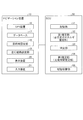
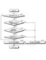
- step ST6 the drive switching unit 55 of the ECU 50 of the travel control device 1 selects the EV mode and stops the engine 5 in step ST61 in FIG. Maintain and drive only MG6. Then, the drive switching unit 55 of the ECU 50 of the travel control device 1 causes the hybrid vehicle 2 to travel using only the travel driving force of the MG 6 and proceeds to step ST62. In step ST62, the drive switching unit 55 of the ECU 50 of the travel control device 1 determines whether or not the SOC of the battery 9 is below a predetermined second predetermined value.
- the second predetermined value is a value that is different from the first predetermined value described above and is sufficiently smaller than the first predetermined value.
- step ST63 the SOC of the battery 9 is determined to be a predetermined second predetermined value. If it is determined that the value does not fall below, step ST62 is repeated.
- step ST63 the drive switching unit 55 of the ECU 50 of the travel control device 1 selects the HV mode and drives the engine 5. Then, the drive switching unit 55 of the ECU 50 of the travel control device 1 causes the hybrid vehicle 2 to travel with at least the travel driving force of the engine 5 and proceeds to step ST64. Also in this step ST64, the drive switching unit 55 of the ECU 50 of the travel control device 1 operates the engine 5 in the most efficient state as in the above-described step ST74, while the travel drive force and the engine brake force.
- the MG 6 is compensated for excess and deficiency, and the battery 9 is charged with the electric power generated by the MG 6.
- step ST64 the drive switching unit 55 of the ECU 50 of the travel control device 1 determines whether or not the SOC of the battery 9 is below the first predetermined value described above.
- the step ST64 is repeated, and when it is determined that the SOC of the battery 9 is not lower than the first predetermined value, the step Returning to ST61, the EV mode is selected.
- the drive switching unit 55 of the ECU 50 of the travel control device 1 repeats step ST62 until the SOC falls below the second predetermined value that is sufficiently smaller than the first predetermined value, and maintains the EV mode.
- the hybrid vehicle 2 is driven only by the driving force of the MG 6. That is, the drive switching unit 55 of the ECU 50 of the travel control device 1 causes the hybrid vehicle 2 to travel only by the travel driving force of the MG 6 until the SOC falls below the second predetermined value that is sufficiently smaller than the first predetermined value.
- the EV mode and the HV mode are selected so as to increase the frequency of the EV mode by prohibiting the frequency of the HV mode at the time of high load until the destination is reached.
- the drive switching unit 55 of the travel control device 1 sets the first travel plan when the estimated charging time estimated by the second estimating unit 54 is long as the second traveling plan when the estimated expected charging time is short.
- the EV mode and the HV mode are selected so that the frequency of the EV mode increases and the frequency of the HV mode at high load is suppressed until the destination is reached, rather than the travel plan.
- the first travel plan corresponds to a case where the expected charging time estimated by the second estimation unit 54 is long, and the second travel plan is the expected charging time estimated by the second estimation unit 54. Corresponds to the case where is short.
- the electric power charged in the battery 9 can be reliably used for the travel of the hybrid vehicle 2, and the deterioration of the fuel consumption due to the driving of the engine 5 is suppressed, and the running cost of the hybrid vehicle 2 as a whole is further reduced. Can be possible.
- the HV mode at the time of high load is allowed, so that the battery 9 can be charged before reaching the destination. Therefore, it is possible to suppress charging of the battery 9 during traveling after the departure from the destination, to suppress deterioration of fuel consumption, and to further reduce the running cost of the hybrid vehicle 2 as a whole.
- the second estimation unit 54 estimates the expected charging time at the destination based on the actual charging time for each stop position of the hybrid vehicle 2 stored in the storage unit 51, the expected charging time, that is, the battery at the destination. 9 can be estimated accurately.
- the second predetermined value is set to a value smaller than the first predetermined value, in the first travel plan, the electric power charged in the battery 9 can be reliably used for the travel of the hybrid vehicle 2. Further, the deterioration of fuel consumption due to the driving of the engine 5 can be reliably suppressed, and the running cost of the hybrid vehicle 2 as a whole can be reliably reduced.
- the drive switching unit 55 determines the first travel plan. select. For this reason, when the second estimation unit 54 uses the above-described default value as the expected charging time, or when the destination is not set in the destination setting unit 18, the SOC falls below the second predetermined value. Since the engine 5 is not driven even in a high load state, the running cost of the hybrid vehicle 2 as a whole can be reliably reduced. Further, even when the second estimation unit 54 sets the above-described default value as the expected charging time or when the destination is not set in the destination setting unit 18, if the SOC falls below the second predetermined value, the HV mode is set. Since the hybrid vehicle 2 is driven with the driving force of the engine 5 selected, the SOC of the battery 9 can be recovered.
- the travel control device 1 of the present embodiment drives the engine 5 even in a high load state until the SOC falls below the second predetermined value, as shown in FIG. Therefore, the running cost of the hybrid vehicle 2 as a whole can be reliably reduced.
- the horizontal axis in FIG. 6 indicates the travel distance of the hybrid vehicle 2
- the vertical axis indicates the SOC of the battery 9.
- Comparative Example 1 selects only the second travel plan, selects the HV mode in a high load state between ab, selects the HV mode for the SOC to fall below the first predetermined value between dB, and the remaining In the comparative example 2, only the second travel plan is selected, the EV mode is selected between 0A, and the SOC is lower than the first predetermined value between AB.
- the conventional example which selects is shown. Comparative Example 1 is indicated by a one-dot chain line in FIG. 6, and Comparative Example 2 is indicated by a dotted line in FIG.
- the present invention 1 shows the above-described embodiment in which the first travel plan, that is, the EV mode is selected in all sections by fully charging the battery at A, and the present invention 2 does not charge the battery at A. Furthermore, the above-described embodiment is shown in which the first travel plan, that is, the EV mode is selected between 0c, and the HV mode is selected because the SOC is lower than the second predetermined value between cB.
- the present invention 1 is indicated by a solid line in FIG. 6, and the present invention 2 is indicated by a two-dot chain line in FIG.
- FIG. 6 is a figure explaining the change of SOC with respect to the travel distance of a comparative example and this invention.
- FIG. 7 is a flowchart for selecting a travel plan of the ECU of the travel control apparatus according to the modification according to the embodiment
- FIG. 8 is a flowchart of the drive switching unit of the ECU of the travel control apparatus according to the modification according to the embodiment. It is explanatory drawing which shows the map for setting the ratio of 1 travel plan.
- the same part as embodiment mentioned above is attached
- the drive switching unit 55 of the ECU 50 of the travel control device 1 performs the first travel plan and the second travel plan based on the expected charging time estimated by the second estimation unit 54 in step ST5a shown in FIG. And set the ratio.
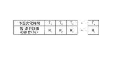
- the drive switching unit 55 stores in advance a map showing the relationship between the estimated expected charging time and the first travel plan shown in FIG. The ratio of the first travel plan corresponding to the estimated charging time is read from the map shown in FIG.
- the expected charging time T 1, and T 2, T 3 ⁇ T n corresponds one-to-one and has, has at the expected charging time T 1> T 2> T 3 > ⁇ > T n, and the ratio R 1> R 2> R 3 > ⁇ > R n.
- the ratio R 1 of the time expected charging time T 1 is 100%, the ratio R n when the expected charging time T n is 0%.
- the drive switching unit 55 reads a ratio corresponding to the expected charging time estimated by the second estimation unit 54 from the map shown in FIG.
- the expected charging time estimated by the second estimating unit 54 does not correspond to any of the expected charging times T 1 , T 2 , T 3 ... T n of the map shown in FIG.
- the ratios R 1 , R 2 , R 3 ... R n corresponding to the expected charging times T 1 , T 2 , T 3 ... T n closest to the expected charging time estimated by the second estimating unit 54 are read. .
- the drive switching unit 55, the expected charging time second estimation unit 54 has estimated longer than expected charging time T 1 the ratio of the first travel plan as a R 1, expected charging second estimation unit 54 has estimated When shorter than the expected charging time T n time, the ratio of the first travel plan and R n.
- the drive switching unit 55 divides the distance to the destination into the distance traveled by the first travel plan and the distance traveled by the second travel plan according to the ratio obtained from the map shown in FIG.
- the hybrid vehicle 2 is caused to travel by switching between the first travel plan and the second travel plan to the destination according to the divided distance.
- the prediction estimated by the second estimation unit 54 is gradually increased by increasing the ratio of traveling in the first travel plan.
- the EV mode and the HV mode are selected so that the frequency of the EV mode increases until the destination is reached, compared to when the expected charging time is short.
- the prediction estimated by the second estimation unit 54 is gradually increased by increasing the ratio of traveling in the first travel plan.
- the EV mode and the HV mode are selected so as to suppress the frequency of the HV mode at the time of high load until the destination is reached, compared to the case where the expected charging time is short.
- the travel control device 1 of the present modified example suppresses the deterioration of fuel consumption due to the drive of the engine 5 and can further reduce the running cost of the hybrid vehicle 2 as a whole. can do.
- FIG. 9 is a flowchart for changing a travel plan of the ECU of the travel control apparatus according to the first disclosure.
- the same parts as those in the embodiment and the modification described above are denoted by the same reference numerals and the description thereof is omitted.
- step ST3a when it is determined that the electric power corresponding to the required travel energy estimated by the determination unit 53 in step ST2 illustrated in FIG. 9 is lower than the current remaining capacity of the battery 9, the travel control device 1 in step ST3a.
- the determination unit 53 of the ECU 50 may be charged from the external power source 14 at the destination set in the destination setting unit 18 with reference to the information of the navigation device 13 and the information stored in the storage unit 51. It is determined whether or not.
- step ST3a it is determined that there is a possibility of charging when the external power source 14 is present at the destination and the battery 9 has been charged by the external power source 14 in the past at the position set as the destination. To do.
- step ST3a when the determination unit 53 of the ECU 50 of the travel control device 1 determines that there is a possibility of charging from the external power source 14 at the destination set in the destination setting unit 18, the process proceeds to step ST6, where there is a possibility. If it is determined that there is not, the process proceeds to step ST7.
- the determination unit 53 of the ECU 50 of the travel control device 1 determines that there is a possibility of charging from the external power source 14 at the destination set in the destination setting unit 18, the first travel plan is executed. Therefore, the deterioration of fuel consumption due to driving of the engine 5 can be suppressed, and the running cost of the hybrid vehicle 2 as a whole can be further reduced.
- FIG. 10 is a flowchart for changing the travel plan of the ECU of the travel control apparatus according to the second disclosed example. Note that, in the disclosure example 2, the same parts as those in the above-described embodiment and modification are denoted by the same reference numerals and description thereof is omitted.
- step ST6 when the determination unit 53 of the ECU 50 of the travel control device 1 determines that the external power source 14 exists at the destination set in the destination setting unit 18 in step ST3 illustrated in FIG. 10, the process proceeds to step ST6. If it is determined that the external power supply 14 does not exist, the process proceeds to step ST7.
- the first travel plan is selected.
- the deterioration of fuel consumption due to driving can be suppressed, and the running cost of the hybrid vehicle 2 as a whole can be further reduced.
- FIG. 11 is a flowchart for changing the travel plan of the ECU of the travel control apparatus according to the third disclosure. Note that, in the disclosure example 3, the same parts as those in the embodiment and the modification described above are denoted by the same reference numerals and the description thereof is omitted.
- step ST4a shown in FIG. 11 the determination unit 53 of the ECU 50 of the travel control device 1 refers to the information in the storage unit 51 in the destination set in the destination setting unit 18 in the past. Then, it is determined whether or not the battery 9 is charged by the external power source 14. If it is determined that the battery 9 is charged, the process proceeds to step ST6. If it is determined that the battery 9 is not charged, the process proceeds to step ST7.
- the determination unit 53 of the ECU 50 of the travel control device 1 determines that the battery 9 is charged at the destination set in the destination setting unit 18, the first travel plan is selected.
- the deterioration of fuel consumption due to driving can be suppressed, and the running cost of the hybrid vehicle 2 as a whole can be further reduced.
- the travel control device 1 according to the above-described embodiment of the present invention is not limited to the above-described embodiment and modifications, and various modifications can be made without changing the gist of the present invention.
- the travel control apparatus according to the present embodiment may be configured by appropriately combining the constituent elements of the embodiment and the modification described above.
- the first predetermined value and the second predetermined value are different from each other, and the second predetermined value is smaller than the first predetermined value.
- the first predetermined value and the second predetermined value may be made equal.
- the HV mode is not selected even in a high load state, so that deterioration of fuel consumption due to driving of the engine 5 is suppressed, and the running cost of the hybrid vehicle 2 as a whole is further reduced. Can be made possible.
- MG6 which has a power running function and a regeneration function was used as a motor
- this invention is not limited to this,
- a motor provided with a power running function and a regeneration function are provided.
- a generator e.g., a motor provided with a power running function and a regeneration function.
Landscapes
- Engineering & Computer Science (AREA)
- Transportation (AREA)
- Mechanical Engineering (AREA)
- Chemical & Material Sciences (AREA)
- Combustion & Propulsion (AREA)
- Automation & Control Theory (AREA)
- Life Sciences & Earth Sciences (AREA)
- Sustainable Development (AREA)
- Sustainable Energy (AREA)
- Power Engineering (AREA)
- Electric Propulsion And Braking For Vehicles (AREA)
- Hybrid Electric Vehicles (AREA)
Abstract
La présente invention concerne un dispositif de commande de déplacement permettant de réduire davantage les frais d'entretien d'un véhicule hybride. Le dispositif de commande de déplacement (1) sélectionne un mode de déplacement d'un véhicule hybride comprenant une batterie qui peut être chargée par une puissance provenant d'une source d'alimentation externe, un moteur générateur (MG) qui génère une puissance d'entraînement de déplacement provenant d'une alimentation par batterie et un moteur qui génère une puissance d'entraînement de déplacement. Le dispositif de commande de déplacement (1) comprend une seconde unité d'estimation (54) et une unité de commutation d'entraînement (55). La seconde unité d'estimation (54) estime un temps de charge prévu pendant lequel la charge de la batterie est possible lors du trajet vers la destination. Lorsque le temps de charge prévu estimé par la seconde unité d'estimation (54) est long, l'unité de commutation d'entraînement (55) augmente la fréquence de mode EV jusqu'à ce que la destination soit atteinte par rapport à lorsque le temps de charge prévu est court.
Priority Applications (3)
| Application Number | Priority Date | Filing Date | Title |
|---|---|---|---|
| US14/374,329 US9283953B2 (en) | 2012-01-26 | 2012-12-11 | Travel control device |
| EP12866806.8A EP2808218B1 (fr) | 2012-01-26 | 2012-12-11 | Dispositif de commande de déplacement |
| CN201280068090.7A CN104066636B (zh) | 2012-01-26 | 2012-12-11 | 行驶控制装置 |
Applications Claiming Priority (2)
| Application Number | Priority Date | Filing Date | Title |
|---|---|---|---|
| JP2012014515A JP5609898B2 (ja) | 2012-01-26 | 2012-01-26 | 走行制御装置 |
| JP2012-014515 | 2012-01-26 |
Publications (1)
| Publication Number | Publication Date |
|---|---|
| WO2013111464A1 true WO2013111464A1 (fr) | 2013-08-01 |
Family
ID=48873205
Family Applications (1)
| Application Number | Title | Priority Date | Filing Date |
|---|---|---|---|
| PCT/JP2012/082107 Ceased WO2013111464A1 (fr) | 2012-01-26 | 2012-12-11 | Dispositif de commande de déplacement |
Country Status (5)
| Country | Link |
|---|---|
| US (1) | US9283953B2 (fr) |
| EP (1) | EP2808218B1 (fr) |
| JP (1) | JP5609898B2 (fr) |
| CN (1) | CN104066636B (fr) |
| WO (1) | WO2013111464A1 (fr) |
Cited By (1)
| Publication number | Priority date | Publication date | Assignee | Title |
|---|---|---|---|---|
| CN110091860A (zh) * | 2018-01-30 | 2019-08-06 | 丰田自动车株式会社 | 电动车辆以及电动车辆的控制方法 |
Families Citing this family (19)
| Publication number | Priority date | Publication date | Assignee | Title |
|---|---|---|---|---|
| TWI479772B (zh) * | 2013-02-21 | 2015-04-01 | 台達電子工業股份有限公司 | 電動車充電系統及其適用之充電方法 |
| DE102013208320A1 (de) * | 2013-05-07 | 2014-11-13 | Deere & Company | Verfahren zur Bestimmung eines Kontrollparameters eines Leistungs- oder Drehmomentverteilungsreglers für einen Hybridantrieb einer Arbeitsmaschine |
| WO2015004782A1 (fr) * | 2013-07-11 | 2015-01-15 | トヨタ自動車株式会社 | Véhicule hybride |
| KR101509965B1 (ko) * | 2013-11-11 | 2015-04-07 | 현대자동차주식회사 | 배터리 충전 장치 및 방법 |
| JP6201808B2 (ja) * | 2014-02-24 | 2017-09-27 | トヨタ自動車株式会社 | 移動支援装置、移動支援方法、及び運転支援システム |
| JP6183244B2 (ja) * | 2014-02-24 | 2017-08-23 | トヨタ自動車株式会社 | 移動支援装置及び移動支援方法 |
| EP3144690B1 (fr) * | 2015-09-17 | 2018-07-11 | Volvo Car Corporation | Procédé et appareil permettant de déterminer l'état d'une batterie dans un véhicule |
| JP6583244B2 (ja) * | 2016-12-19 | 2019-10-02 | トヨタ自動車株式会社 | ハイブリッド車両の制御装置 |
| KR102443338B1 (ko) | 2017-09-12 | 2022-09-15 | 현대자동차주식회사 | 배터리 충전 제어방법 및 시스템 |
| JP6992460B2 (ja) * | 2017-12-05 | 2022-01-13 | トヨタ自動車株式会社 | ハイブリッド自動車およびこれに搭載される制御装置 |
| JP6897528B2 (ja) * | 2017-12-05 | 2021-06-30 | トヨタ自動車株式会社 | ハイブリッド車両の制御装置 |
| MX2020006164A (es) * | 2017-12-15 | 2020-08-13 | Nissan Motor | Metodo de control para vehiculo hibrido y aparato de control para vehiculo hibrido. |
| US11560136B2 (en) | 2018-03-02 | 2023-01-24 | Toyota Jidosha Kabushiki Kaisha | Control device |
| JP6939689B2 (ja) * | 2018-04-19 | 2021-09-22 | トヨタ自動車株式会社 | ハイブリッド車両の制御装置 |
| JP7067387B2 (ja) | 2018-09-21 | 2022-05-16 | トヨタ自動車株式会社 | ハイブリッド車両の制御装置 |
| JP7369617B2 (ja) * | 2019-12-26 | 2023-10-26 | 日産自動車株式会社 | 発電機制御方法及び発電機制御装置 |
| JP7652045B2 (ja) * | 2021-10-15 | 2025-03-27 | トヨタ自動車株式会社 | 充電制御装置 |
| JP7544084B2 (ja) * | 2022-02-09 | 2024-09-03 | トヨタ自動車株式会社 | 車両 |
| US12377881B2 (en) | 2022-06-27 | 2025-08-05 | State Farm Mutual Automobile Insurance Company | Delivery hand off procedure when electric vehicle (EV) is about to lose power |
Citations (2)
| Publication number | Priority date | Publication date | Assignee | Title |
|---|---|---|---|---|
| JP2008094230A (ja) * | 2006-10-11 | 2008-04-24 | Toyota Motor Corp | ハイブリッド車両、ハイブリッド車両の制御方法、その制御方法をコンピュータに実行させるためのプログラム、およびそのプログラムを記録したコンピュータ読み取り可能な記録媒体 |
| JP2010000884A (ja) | 2008-06-19 | 2010-01-07 | Denso Corp | ハイブリッド車両の制御装置 |
Family Cites Families (10)
| Publication number | Priority date | Publication date | Assignee | Title |
|---|---|---|---|---|
| US6814170B2 (en) * | 2001-07-18 | 2004-11-09 | Nissan Motor Co., Ltd. | Hybrid vehicle |
| JP4517984B2 (ja) | 2005-09-01 | 2010-08-04 | トヨタ自動車株式会社 | ハイブリッド自動車 |
| JP4692466B2 (ja) | 2006-10-20 | 2011-06-01 | トヨタ自動車株式会社 | ハイブリッド車両の制御装置 |
| JP4788643B2 (ja) * | 2007-04-23 | 2011-10-05 | 株式会社デンソー | ハイブリッド車両用の充放電制御装置および当該充放電制御装置用のプログラム |
| JP5181732B2 (ja) * | 2007-05-02 | 2013-04-10 | 日産自動車株式会社 | ハイブリッド車両のモード切り替え制御装置 |
| EP2247479A4 (fr) * | 2008-03-03 | 2018-02-07 | Nissan Motor Co., Ltd. | Appareil de commande et procédé de commande d'un véhicule hybride |
| CN101585359B (zh) * | 2008-05-22 | 2013-03-06 | 杨伟斌 | 可外接充电型混合动力汽车电量保持阶段的能量管理方法 |
| JP5029494B2 (ja) * | 2008-05-27 | 2012-09-19 | アイシン・エィ・ダブリュ株式会社 | 走行エネルギー学習装置、方法およびプログラム |
| US8170737B2 (en) * | 2009-04-30 | 2012-05-01 | GM Global Technology Operations LLC | Method of controlling vehicle powertrain and vehicle control system |
| DE102009028922A1 (de) | 2009-08-27 | 2011-03-03 | Robert Bosch Gmbh | Verfahren zum Betrieb eines Hybridfahrzeugs und Hybridsteuerung |
-
2012
- 2012-01-26 JP JP2012014515A patent/JP5609898B2/ja active Active
- 2012-12-11 CN CN201280068090.7A patent/CN104066636B/zh active Active
- 2012-12-11 US US14/374,329 patent/US9283953B2/en active Active
- 2012-12-11 WO PCT/JP2012/082107 patent/WO2013111464A1/fr not_active Ceased
- 2012-12-11 EP EP12866806.8A patent/EP2808218B1/fr active Active
Patent Citations (2)
| Publication number | Priority date | Publication date | Assignee | Title |
|---|---|---|---|---|
| JP2008094230A (ja) * | 2006-10-11 | 2008-04-24 | Toyota Motor Corp | ハイブリッド車両、ハイブリッド車両の制御方法、その制御方法をコンピュータに実行させるためのプログラム、およびそのプログラムを記録したコンピュータ読み取り可能な記録媒体 |
| JP2010000884A (ja) | 2008-06-19 | 2010-01-07 | Denso Corp | ハイブリッド車両の制御装置 |
Non-Patent Citations (1)
| Title |
|---|
| See also references of EP2808218A4 |
Cited By (1)
| Publication number | Priority date | Publication date | Assignee | Title |
|---|---|---|---|---|
| CN110091860A (zh) * | 2018-01-30 | 2019-08-06 | 丰田自动车株式会社 | 电动车辆以及电动车辆的控制方法 |
Also Published As
| Publication number | Publication date |
|---|---|
| US20150019060A1 (en) | 2015-01-15 |
| JP2013154664A (ja) | 2013-08-15 |
| CN104066636B (zh) | 2015-12-09 |
| EP2808218A4 (fr) | 2015-07-29 |
| EP2808218B1 (fr) | 2017-04-05 |
| EP2808218A1 (fr) | 2014-12-03 |
| US9283953B2 (en) | 2016-03-15 |
| JP5609898B2 (ja) | 2014-10-22 |
| CN104066636A (zh) | 2014-09-24 |
Similar Documents
| Publication | Publication Date | Title |
|---|---|---|
| JP5609898B2 (ja) | 走行制御装置 | |
| CN111231688B (zh) | 车辆及控制车辆的方法 | |
| KR101371476B1 (ko) | 하이브리드 자동차의 배터리 충전 방법 및 시스템 | |
| JP5673862B2 (ja) | 車両および車両用制御方法 | |
| US20120330505A1 (en) | Vehicle control device | |
| KR101836250B1 (ko) | 구동 모터를 구비한 차량의 dc 컨버터의 출력 전압을 제어하는 방법 및 장치 | |
| KR101714205B1 (ko) | 하이브리드 차량의 주행 모드 제어 장치 및 방법 | |
| WO2013035730A1 (fr) | Dispositif de commande et procédé de commande de véhicule hybride | |
| AU2007318704A1 (en) | Indication apparatus for hybrid vehicle | |
| US9770989B2 (en) | Vehicle display device | |
| WO2012101802A1 (fr) | Véhicule, et procédé de commande de véhicule | |
| JP4165481B2 (ja) | ハイブリッド電気自動車の制御装置 | |
| JP5644868B2 (ja) | 車両および車両の制御方法 | |
| JP2013141858A (ja) | ハイブリッド車両の制御装置 | |
| JP2010280334A (ja) | 車両用制御装置 | |
| JP2011221620A (ja) | 車両制御装置及び車両制御システム | |
| JP5185052B2 (ja) | 車両の制御装置および制御方法 | |
| JP2013052797A (ja) | 車両の制御装置および制御方法 | |
| JP2012232671A (ja) | 車両 | |
| JP2014097762A (ja) | 走行制御装置 | |
| CN103476655B (zh) | 车辆和车辆用控制方法 | |
| JP6686384B2 (ja) | ハイブリッド車両の回生電力量制御システム、ハイブリッド車両及びハイブリッド車両の回生電力量制御方法 | |
| WO2012137301A1 (fr) | Véhicule et son procédé de commande | |
| JP2012162097A (ja) | 車両 | |
| WO2012105019A1 (fr) | Véhicule et procédé de commande de véhicule |
Legal Events
| Date | Code | Title | Description |
|---|---|---|---|
| 121 | Ep: the epo has been informed by wipo that ep was designated in this application |
Ref document number: 12866806 Country of ref document: EP Kind code of ref document: A1 |
|
| REEP | Request for entry into the european phase |
Ref document number: 2012866806 Country of ref document: EP |
|
| WWE | Wipo information: entry into national phase |
Ref document number: 2012866806 Country of ref document: EP |
|
| WWE | Wipo information: entry into national phase |
Ref document number: 14374329 Country of ref document: US |
|
| NENP | Non-entry into the national phase |
Ref country code: DE |