WO2013111748A1 - 接続面を備えた継手と管継手を備えた管及びそれらで構成した配管構造 - Google Patents
接続面を備えた継手と管継手を備えた管及びそれらで構成した配管構造 Download PDFInfo
- Publication number
- WO2013111748A1 WO2013111748A1 PCT/JP2013/051194 JP2013051194W WO2013111748A1 WO 2013111748 A1 WO2013111748 A1 WO 2013111748A1 JP 2013051194 W JP2013051194 W JP 2013051194W WO 2013111748 A1 WO2013111748 A1 WO 2013111748A1
- Authority
- WO
- WIPO (PCT)
- Prior art keywords
- pipe
- joint
- connection surface
- connection
- hole
- Prior art date
- Legal status (The legal status is an assumption and is not a legal conclusion. Google has not performed a legal analysis and makes no representation as to the accuracy of the status listed.)
- Ceased
Links
Images








Classifications
-
- F—MECHANICAL ENGINEERING; LIGHTING; HEATING; WEAPONS; BLASTING
- F16—ENGINEERING ELEMENTS AND UNITS; GENERAL MEASURES FOR PRODUCING AND MAINTAINING EFFECTIVE FUNCTIONING OF MACHINES OR INSTALLATIONS; THERMAL INSULATION IN GENERAL
- F16L—PIPES; JOINTS OR FITTINGS FOR PIPES; SUPPORTS FOR PIPES, CABLES OR PROTECTIVE TUBING; MEANS FOR THERMAL INSULATION IN GENERAL
- F16L23/00—Flanged joints
- F16L23/02—Flanged joints the flanges being connected by members tensioned axially
- F16L23/024—Flanged joints the flanges being connected by members tensioned axially characterised by how the flanges are joined to, or form an extension of, the pipes
- F16L23/026—Flanged joints the flanges being connected by members tensioned axially characterised by how the flanges are joined to, or form an extension of, the pipes by welding
-
- F—MECHANICAL ENGINEERING; LIGHTING; HEATING; WEAPONS; BLASTING
- F16—ENGINEERING ELEMENTS AND UNITS; GENERAL MEASURES FOR PRODUCING AND MAINTAINING EFFECTIVE FUNCTIONING OF MACHINES OR INSTALLATIONS; THERMAL INSULATION IN GENERAL
- F16L—PIPES; JOINTS OR FITTINGS FOR PIPES; SUPPORTS FOR PIPES, CABLES OR PROTECTIVE TUBING; MEANS FOR THERMAL INSULATION IN GENERAL
- F16L23/00—Flanged joints
- F16L23/12—Flanged joints specially adapted for particular pipes
-
- F—MECHANICAL ENGINEERING; LIGHTING; HEATING; WEAPONS; BLASTING
- F16—ENGINEERING ELEMENTS AND UNITS; GENERAL MEASURES FOR PRODUCING AND MAINTAINING EFFECTIVE FUNCTIONING OF MACHINES OR INSTALLATIONS; THERMAL INSULATION IN GENERAL
- F16L—PIPES; JOINTS OR FITTINGS FOR PIPES; SUPPORTS FOR PIPES, CABLES OR PROTECTIVE TUBING; MEANS FOR THERMAL INSULATION IN GENERAL
- F16L39/00—Joints or fittings for double-walled or multi-channel pipes or pipe assemblies
- F16L39/06—Joints or fittings for double-walled or multi-channel pipes or pipe assemblies of the multiline swivel type, e.g. comprising a plurality of axially mounted modules
-
- F—MECHANICAL ENGINEERING; LIGHTING; HEATING; WEAPONS; BLASTING
- F16—ENGINEERING ELEMENTS AND UNITS; GENERAL MEASURES FOR PRODUCING AND MAINTAINING EFFECTIVE FUNCTIONING OF MACHINES OR INSTALLATIONS; THERMAL INSULATION IN GENERAL
- F16L—PIPES; JOINTS OR FITTINGS FOR PIPES; SUPPORTS FOR PIPES, CABLES OR PROTECTIVE TUBING; MEANS FOR THERMAL INSULATION IN GENERAL
- F16L41/00—Branching pipes; Joining pipes to walls
- F16L41/02—Branch units, e.g. made in one piece, welded, riveted
- F16L41/021—T- or cross-pieces
-
- F—MECHANICAL ENGINEERING; LIGHTING; HEATING; WEAPONS; BLASTING
- F16—ENGINEERING ELEMENTS AND UNITS; GENERAL MEASURES FOR PRODUCING AND MAINTAINING EFFECTIVE FUNCTIONING OF MACHINES OR INSTALLATIONS; THERMAL INSULATION IN GENERAL
- F16L—PIPES; JOINTS OR FITTINGS FOR PIPES; SUPPORTS FOR PIPES, CABLES OR PROTECTIVE TUBING; MEANS FOR THERMAL INSULATION IN GENERAL
- F16L41/00—Branching pipes; Joining pipes to walls
- F16L41/02—Branch units, e.g. made in one piece, welded, riveted
- F16L41/03—Branch units, e.g. made in one piece, welded, riveted comprising junction pieces for four or more pipe members
-
- F—MECHANICAL ENGINEERING; LIGHTING; HEATING; WEAPONS; BLASTING
- F16—ENGINEERING ELEMENTS AND UNITS; GENERAL MEASURES FOR PRODUCING AND MAINTAINING EFFECTIVE FUNCTIONING OF MACHINES OR INSTALLATIONS; THERMAL INSULATION IN GENERAL
- F16L—PIPES; JOINTS OR FITTINGS FOR PIPES; SUPPORTS FOR PIPES, CABLES OR PROTECTIVE TUBING; MEANS FOR THERMAL INSULATION IN GENERAL
- F16L41/00—Branching pipes; Joining pipes to walls
- F16L41/08—Joining pipes to walls or pipes, the joined pipe axis being perpendicular to the plane of a wall or to the axis of another pipe
- F16L41/086—Joining pipes to walls or pipes, the joined pipe axis being perpendicular to the plane of a wall or to the axis of another pipe fixed with screws
-
- F—MECHANICAL ENGINEERING; LIGHTING; HEATING; WEAPONS; BLASTING
- F16—ENGINEERING ELEMENTS AND UNITS; GENERAL MEASURES FOR PRODUCING AND MAINTAINING EFFECTIVE FUNCTIONING OF MACHINES OR INSTALLATIONS; THERMAL INSULATION IN GENERAL
- F16L—PIPES; JOINTS OR FITTINGS FOR PIPES; SUPPORTS FOR PIPES, CABLES OR PROTECTIVE TUBING; MEANS FOR THERMAL INSULATION IN GENERAL
- F16L43/00—Bends; Siphons
- F16L43/001—Bends; Siphons made of metal
-
- F—MECHANICAL ENGINEERING; LIGHTING; HEATING; WEAPONS; BLASTING
- F16—ENGINEERING ELEMENTS AND UNITS; GENERAL MEASURES FOR PRODUCING AND MAINTAINING EFFECTIVE FUNCTIONING OF MACHINES OR INSTALLATIONS; THERMAL INSULATION IN GENERAL
- F16L—PIPES; JOINTS OR FITTINGS FOR PIPES; SUPPORTS FOR PIPES, CABLES OR PROTECTIVE TUBING; MEANS FOR THERMAL INSULATION IN GENERAL
- F16L43/00—Bends; Siphons
- F16L43/001—Bends; Siphons made of metal
- F16L43/005—Return bends
-
- E—FIXED CONSTRUCTIONS
- E02—HYDRAULIC ENGINEERING; FOUNDATIONS; SOIL SHIFTING
- E02F—DREDGING; SOIL-SHIFTING
- E02F9/00—Component parts of dredgers or soil-shifting machines, not restricted to one of the kinds covered by groups E02F3/00 - E02F7/00
- E02F9/20—Drives; Control devices
- E02F9/22—Hydraulic or pneumatic drives
- E02F9/2264—Arrangements or adaptations of elements for hydraulic drives
- E02F9/2275—Hoses and supports therefor and protection therefor
Definitions
- the present invention provides a hydraulic circuit that supplies and discharges hydraulic pressure oil from a hydraulic fluid source to hydraulic equipment such as hydraulic cylinders and hydraulic motors, which are driving equipment used to drive a dam sluice, river movable weir or industrial machinery.
- the present invention relates to a joint provided with a connection surface used for piping for construction, a pipe provided with a pipe joint, and a piping structure constituted by them.
- Hydraulic equipment such as dam sluices, river movable weirs or hydraulic cylinders that drive industrial machinery, hydraulic motors, etc., supply and discharge hydraulic pressure oil from a pressure fluid source via a hydraulic circuit, Since it operates driven equipment such as tide doors and industrial machinery, it is installed near the driven equipment.
- the pressure fluid source is a device in which electronic devices for controlling the supply and discharge of working pressure oil or a switching valve are integrated in a hydraulic tank, a hydraulic pump, and a hydraulic device, and is vulnerable to wind and rain, and the entire device does not operate due to its failure Therefore, a building is set up and installed in the building. For this reason, the distance from the pressure fluid source to the hydraulic equipment becomes long.
- a straight pipe portion constituting the hydraulic circuit is welded to an end of a steel pipe having a specified length (about 6 meters) with a socket which is a plug-weld type pipe joint.
- the bent pipe part can be supported by bending the steel pipe with a bender and welding a socket to the end of the pipe.
- the hydraulic circuit was configured in accordance with the site where piping was performed using elbows, chews, and crosses, which are joints.
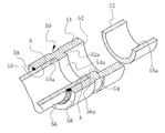
- the socket 50 of the plug-weld type pipe joint constituting the straight pipe portion constitutes a hydraulic circuit at both ends of the straight pipe-shaped main body 51, as shown in FIG. Tube end insertion holes 52 and 53 into which end portions 55a and 56a of the tubes 55 and 56 are inserted are provided.
- a protrusion 54 that forms a small diameter hole 54a having a diameter corresponding to the inner diameter of the tubes 55 and 56.
- the protrusion 54 and the tube end insertion holes 52 and 53 are provided. Steps 52a and 53a are provided between the two.
- the tube 55 and the tube 56 are inserted until the end portion 55a of the tube 55 comes into contact with the stepped portion 52a of the tube end insertion hole 52 as shown on the right side of FIG.
- the straight pipe part of the hydraulic circuit is configured by welding the outer periphery of the pipe 55 and the socket 50 at the welded part 58.
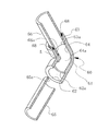
- the elbow 60 of a plug-weld type pipe joint constituting the curved pipe portion is a pipe constituting a hydraulic circuit at both ends of the curved pipe-shaped main body 61 as shown in FIG.
- Pipe end insertion holes 62 and 63 into which end portions 65a and 66a of 65 and 66 are inserted are provided.
- a protrusion 64 that forms a small diameter hole 64a having a diameter corresponding to the inner diameter of the tubes 65 and 66.
- the protrusion 64 and the tube end insertion holes 62 and 63 are provided. Steps 62a and 63a are provided between the two.
- the end portion 65a of the tube 65 is inserted until the tip end thereof abuts on the stepped portion 62a, and the outer periphery of the tube 65 and the curved pipe-shaped main body 61 are welded by a welded portion (similar to the welded portion 68). Then, the end 66a of the tube 66 is inserted until the tip of the tube 66 comes into contact with the stepped portion 63a, and the outer periphery of the tube 66 and the bent tube-shaped main body 61 are welded by the welded portion 68 to constitute the curved tube portion of the hydraulic circuit. .
- the socket 50 and the elbow 60 have pipe ends (end portions 55a, 56a, 65a, 66a) and the like (tube end insertion holes).
- a straight pipe portion and a curved pipe portion of the piping structure are formed by welding the outer periphery of the pipe and the like, the socket 50, and the elbow 60 by inserting into the holes 52, 53, 62, 63).
- the diameter of the pipe end insertion hole or the like of the pipe joint into which the end of the pipe or the like is inserted is slightly larger than the outer diameter of the pipe (about 0.5 mm at a nominal diameter of 20A) in order to improve workability. Since it is large, a gap A is formed between the outer periphery of the tube and the tube end insertion hole. For this reason, the surface of the pipe is oxidized by heat generated by welding the inserted pipe and the pipe joint, and remains as an oxide film on the surface of the pipe, that is, the gap A.
- This oxide film is thin and sharp and is an iron oxide, so it is extremely hard and leaves the gap A during operation of the hydraulic system, floats in the pressure oil, rides on the pressure oil, and circulates in the hydraulic line. It enters the hydraulic equipment, control valves, and hydraulic equipment, damages the sliding surfaces and causes contamination.
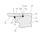
- Patent Document 1 As shown in FIGS. 18A and 18B, an end portion 76a of a tube 76 inserted into a tube end insertion hole 73 of a pipe joint 70 and a stepped portion 73a of the tube end insertion hole 73 are described.
- positioning the welding width h between them, and welding with the welding part 79 is shown.
- a welding width h is configured and arranged between the end portion 86 a of the pipe 86 inserted into the pipe end insertion hole 83 of the pipe joint 80 and the step portion 83 a of the pipe end insertion hole 83.
- tube 86 by welding by 89 is shown.
- a gap h1 is formed between the end portion 76a and the stepped portion 73a because the welded portion 79 welds the tip of the end portion 76a of the pipe 76 and the stepped portion 73a within the weld width h. Is done.
- a gap h1 is also formed in the connection configuration of the pipe joint 80 and the pipe 86.
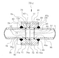
- a straight pipe structure 70c shown in FIG. 19 has the same structure as the pipe structure including the pipe joint 70, and the pipe structure including the pipe joint 80 is fastened by the hexagonal socket bolt 82. Composed.
- connection hole 71 a of the pipe joint 70 has a configuration in which four connection holes 74 are provided concentrically with the connection hole 74.
- the connecting hole 81a of the pipe joint 80 screwed to the pipe joint 70 is provided at the same position as the four connecting holes 71a.
- the connection hole 71a and the connection hole 81a have a screw hole structure and a through hole structure, and when one of them has a screw hole structure, the other has a through hole structure. This configuration is defined in JIS B 2291.
- connection hole 71 a of the pipe joint 70 is a through hole
- connection hole 81 a of the pipe joint 80 is an internal thread and the connection surface 77 of the pipe joint 70
- the structure provided with the O-ring 72 that seals between the pipe joint 70 and the pipe joint 80 is different, and the other configuration is substantially the same, so that it will be described as necessary and detailed description will be omitted.
- the straight pipe structure 70C configured by fastening the pipe joint 70 and the pipe joint 80 with four hexagon socket head bolts 82 has a gap h1 corresponding to the number of pipe joints used in the pipe structure constituting the straight pipe. Will exist.
- the pipe with the pipe joint 70 disclosed in Patent Document 1 is inserted into the pipe end insertion hole of the pipe joint, and the welded portion 78 and the welded portion 79 which are before and after the inserted portion are welded to the pipe end. Since the gap A formed between the insertion hole and the pipe is sealed, contamination such as an oxide film in the gap A does not flow into the hydraulic circuit. However, since the gap h1 is provided with a plurality of recesses (as many as the number of pipe joints), the above-mentioned various contaminants and air are stored, causing the hydraulic oil to deteriorate early.
- a joint having a connection surface according to the first invention is a first connection surface and a second connection surface connected to a connection body such as a port of a hydraulic device having a passage through which hydraulic fluid flows or a joint of a pipe, A first opening end that opens to the first connection surface; a first connection hole that opens to the first connection surface and is arranged concentrically with the first opening end; and a second opening end that opens to the second connection surface And a second connecting hole that opens to the second connection surface and is concentrically arranged with the second opening end, and a communication passage that communicates the first opening end and the second opening end.
- the first plane including the first connection surface of the main body intersects the second plane including the second connection surface, and the first connection surface is a square centered on the first opening end,
- the second connection surface includes a square centered on the second opening end, and one side of the second connection surface is closer to the first connection hole than the one side of the square. And characterized in that a rectangular length obtained by adding more than the length of the.
- the joint having the connection surface having the above-described configuration has an effect of not forming an air or contamination storage place that is a cause of contamination due to a smooth flow path configuration in which no gaps or welds exist in the communication passage and the connection surface.
- the pipe having the pipe joint according to the second aspect of the present invention includes a pipe constituting the pipe, a pipe end insertion hole into which the end of the pipe is inserted with a gap, and the pipe end insertion hole.
- a joint provided with a connection hole having a diameter corresponding to the inner diameter of the tube and a connection surface through which the connection hole opens, and an inner surface of an end of the tube inserted into the tube end insertion hole and an inner surface of the connection hole The outer circumference of the tube and the joint are welded together.
- the pipe having the pipe joint having the above-described configuration is configured to weld the end of the pipe inserted into the pipe end insertion hole and the inner surface of the connection hole, a recess is formed on the inner surface of the pipe having the pipe joint. Therefore, contamination caused by welding is sealed and a smooth flow path is formed, and the effect of reducing the stress due to hydraulic pressure acting on the outer periphery of the pipe and the welded portion of the joint is obtained.
- a pipe structure including a first connection surface and a second connection surface connected to a connection body such as a port of a hydraulic device having a passage through which hydraulic oil flows or a joint of the pipe, and the first connection surface.
- a connection body such as a port of a hydraulic device having a passage through which hydraulic oil flows or a joint of the pipe, and the first connection surface.
- a first opening end that opens to the first connection surface, a first connection hole that is concentrically arranged with the first opening end, a second opening end that opens to the second connection surface
- a main body comprising: a second connecting hole that opens in two connection surfaces and is arranged concentrically with the second opening end; and a communication passage that communicates the first opening end and the second opening end.
- a first plane including the first connection surface intersects a second plane including the second connection surface, and the first connection surface is a square centered on the first opening end, and the second connection surface Including a square centered at the second opening end, and one side of which is equal to or greater than the depth of the first connection hole from the one side of the square.
- the pipe joint of the pipe is fixed by screw connection.
- the piping structure having the above configuration is a configuration in which the piping structure constituted by the joint provided with the connection surface and the pipe provided with the pipe joint does not generate contamination, and further does not form a recess on the inner surface. Is formed on a smooth inner surface, and therefore has an effect of preventing the accumulation of contaminants.
- the pipe structure which is a material necessary for piping work
- the joint with connection surface can form a smooth flow path without forming a concave portion or gap to store contamination on the inner surface
- hydraulic oil can be formed at a low pressure. It has an effect that contamination and air in the flow path can be cleaned only by circulation. Furthermore, since it is not necessary to involve welding work in any part of the piping work, all the parts can be produced in the factory.
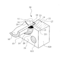
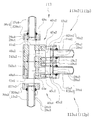
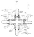
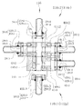
- 1 is a partial perspective view of a tube structure according to a first embodiment of the present invention.
- Sectional drawing of the piping structure which concerns on 5th Example of this invention Sectional drawing of the piping structure which concerns on 6th Example of this invention. Sectional drawing of the piping structure which concerns on 7th Example of this invention. Sectional drawing of the piping structure which concerns on 8th Example of this invention. Sectional drawing of the piping structure which concerns on 9th Example of this invention. Sectional drawing of the intermediate joint which concerns on 9th Example of this invention. Sectional drawing of 10th Example of the piping structure which concerns on 10th Example of this invention. Sectional drawing of 11th Example of the piping structure which concerns on 11th Example of this invention. The perspective view of the pipe
- Sectional drawing of the piping structure which concerns on 16th Example of this invention. The partial expanded sectional view of the conventional pipe structure.
- the partial expanded sectional view of the conventional pipe structure The partial expanded sectional view of the conventional pipe structure.
- the partial expanded sectional view of the conventional pipe structure. The partial expanded sectional view of the conventional pipe structure.
- the partial expanded sectional view of the conventional pipe structure. The partial expanded sectional view of the conventional pipe structure.
- symbol used for drawing of the Example of this invention uses the same number for the same component, and the kind is displayed by adding the capital letter of the alphabet before the number.
- a part that needs to be explained may be displayed by adding an alpha bed after the number, and a part that needs to be explained may be indicated by a sign to omit the explanation.
- an alpha bed may be added after the numerical code to omit detailed description.
- the dimensions or configuration conform to JIS B2219.
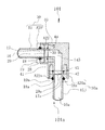
- a piping structure 101 which is a first embodiment of the piping structure shown in FIGS. 1 (a) to 1 (d), has a pipe joint (at one end of a pipe 15 constituting the piping of a hydraulic circuit, as shown in FIG. (Hereinafter referred to as a joint structure))
- a pipe having a pipe joint (hereinafter referred to as a pipe structure) in which A20 is fixed and a pipe joint (hereinafter referred to as a joint structure) B20 is connected to the joint structure A20 at the other end.
- a joint 40 hereinafter referred to as a joint with connecting surface
- FIG.1 (d) the piping structure of the right side part of the piping structure 101 comprised with the connection surface joint 40 and the pipe structure 30a is described as the right side piping structure 101a.
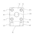
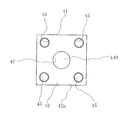
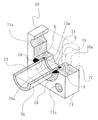
- connection surface 41 of the joint with connection surface 40 is arranged concentrically with the open end 46 of the L-shaped communication passage L43, and is provided at a position matching the connection hole A22 of the joint structure A20. It includes a square 41a (a square indicated by an imaginary line in FIG. 1 (e)) having a connecting hole 44 composed of four screw holes and having an open end 46 as the center. It is configured as a rectangle 41b having one side with a length that is greater than the depth of the connecting hole 45.
- connection surface 42 of the joint with connection surface 40 is formed in the same plane as the second plane intersecting at right angles to the first plane formed by the plane including the connection surface 41, and has an opening as shown in FIG. A square 42 a centered at the end 47, four screw holes provided concentrically with the opening end 47 of the L-shaped communication passage L 43 and provided at a position matching the connection hole A 22 of the through hole of the joint structure A 20.
- the connecting hole 45 is configured.
- the square 41a and the square 42a are the same.
- connection hole 44 and the connection hole 45 are formed as a through hole or a screw hole by making the connection hole 45 a screw hole and providing the connection hole 44 so as not to interfere with the connection hole 45 of the screw hole. Can do.
- connection surfaces 41 and 42 is a first connection surface, and the other constitutes a second connection surface.
- a plane including the first connection surface constitutes a first plane, and a second A plane including the connection surface constitutes the second plane.
- connection surface 41 and the connection surface 42 are not related, and one of them is the first connection surface.
- the other is the second connection surface.
- the joint structure A20 provided at one end of the pipe structure 30 shown in FIG. 12 is a pipe joint having a through hole connecting hole A22 in which the connecting hole is a through hole, and is provided at the other end.
- the joint structure B20 is a pipe joint having a connection hole B22 of a screw hole in which the connection hole is a screw hole.
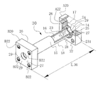
- 12 is a basic configuration for connecting a joint structure A20 and a joint structure B20 of a plurality of pipe structures 30 with hexagon socket bolts 19 to constitute a straight pipe circuit.
- the tube structure 30 shown in FIG. 12 is fixed to one end of the tube 15 and is connected to a connection hole A22 of a through hole that constitutes a through hole into which the hexagonal socket bolt 19 is inserted, and the connection surface 27 opens to an O-ring 39.
- connection structure A20 and the joint structure B20 are joined by tightening the bolt 19 with a hexagonal hole inserted into the connection hole A22 of the through hole into the connection hole B22 of the screw hole. At this time, the mating surface of the connection surface 27 is sealed with the O-ring 39 inserted into the groove 25.
- the O-ring 39 is configured to be provided inside the through hole coupling hole A22, and is always provided on the connection surface of the joint structure A20 in accordance with JIS.
- joint structure A20 and the joint structure B20 are connected by the hexagonal socket bolt 19 to constitute a straight pipe.
- structure of joint structure A20 and joint structure B20 is based on JISB2219.
- the joint structure A20 of the pipe structure 30 includes a pipe end insertion hole 231 into which the end portion 17 of the pipe 15 is inserted with a gap, and is connected to the pipe end insertion hole 231.
- the joint structure B20 is the same as the joint structure A20 except that the through hole connecting hole A22 of the joint structure A20 is replaced with a screw hole connecting hole B22 and the groove 25 is omitted. Accordingly, the joint structure B20 is connected to the joint structure A20 by screwing the hexagon socket head bolt 19 inserted into the through hole connection hole A22 of the joint structure A20 into the screw hole connection hole B22.
- the joint structure A20 and the pipe 15 are formed by inserting the end portion 17 of the pipe 15 into the pipe end insertion hole 231 of the joint structure A20.
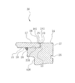
- 18 and the back surface 26 of the joint structure 20 are welded by a welded portion 28, and welding or brazing (brass wax, silver wax, etc.) is performed on the inner surface of the tip 14 of the end portion 17 of the tube 15 and the inner surface of the step portion 23.
- This is a configuration having a portion 29.
- the diameter of the pipe end insertion hole 231 of the joint structure A20 is slightly larger than the outer periphery 18 of the pipe 15 (about 0.5 mm). Since it is configured, a gap 13 (corresponding to the gap A described above) is formed, but the gap 13 is closed by the welded portion 28 and the welded portion 29.
- the welding portion 29 that closes the gap 13 welds the inward surface 241 at the inner end of the connection hole 24 and the inward surface 161 of the end portion 17 as shown in FIG. Closed. Moreover, since the surface of the welded portion 29 is a smooth surface that can be formed by cooling the molten metal, a smooth flow path that does not catch contamination is formed.
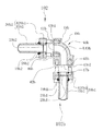
- the joint 40 with connection surface of the piping structure 101 of the first embodiment shown in FIG. 1A is provided with a main body 48, a connection surface 41 and a connection surface 42 which are provided on the main body 48 and intersect at right angles, and this connection surface 41. And an elbow-type joint with connection surface 40 having an elbow-shaped communication passage L43 that opens to the connection surface.
- the elbow-shaped communication passage L43 of the elbow-shaped joint with connection surface 40 has an opening end 46 and an opening end 47 that open at the center of the connection surface 41 of the main body 48 and the connection surface 42 that intersects the connection surface 41 at a right angle.
- the connection surface 41 and the connection surface 42 are provided on the circumference of the opening end 46, and the connection hole 44 is provided at a position corresponding to the connection hole A22 of the through hole of the joint structure A20.
- a hole connection hole 45 provided on the circumference of the opening end 47 and provided at a position corresponding to the connection hole A22a of the through hole of the joint structure A20a.
- connection surface 27 of the tube structure 30 and the groove 25a provided in the tube structure 30a connection surface 27a shown in FIG. 1A are insertion grooves for the O-rings 39 and 39a.
- the joint 40 with the connection surface, the pipe structure 30 and the pipe structure 30a of the piping structure 101 described above are manufactured in a factory and pickled to remove all internal contamination, and then the connection surface is closed by curing. And keep it.
- the piping structure 101 transports the joint 40 with the connection surface and the pipe structures 30 and 30a stored in the above-described state without contamination to the piping work site, and connects the joint 40 with the connection surface and the pipe structures 30 and 30a. It is configured by removing the curing and assembling as shown in FIG.
- connection hole A22 the tip is fixed by screwing into the connecting hole 44 of the screw hole of the main body 42 of the joint 40 with connection surface and tightening.
- connection surface 42 of the joint 40 with connection surface first remove the curing, insert the O-ring into the groove 25a of the tube structure 30a, and then insert the hexagon socket head bolt 19a. Is fixed by being screwed into the connecting hole 45 of the screw hole of the main body 48 of the joint with connection surface 40 and tightening.
- the piping structure 101 configured in this way has no room for contamination to enter in all operations when care is taken so that contamination does not enter when the curing is removed during assembly. Further, since contamination does not occur in a situation where it cannot be visually observed as in welding work, it can be confirmed by visual observation, so that it is possible to take care that contamination does not enter.
- the right-side piping structure 101a of the piping structure 101 in which the pipe structure 30a and the joint 40 with connection surface are combined is a basic configuration of another embodiment.
- the piping structure 102 of the second embodiment shown in FIG. 2 and the piping structure 101 of the first embodiment are different in that the joint 40b with connection surface is formed of a casting.
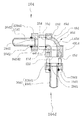
- the joint 40b with connection surface has a configuration in which the main body 48b and the L-shaped communication passage L43b are manufactured by casting, and the connection surface 41b and the connection surface 42b, and the connection holes 44b and 45b of the screw holes are machined. .
- the L-shaped communication path L43b of the main body 48b of the joint with connection surface 40b is made of a casting, as shown in FIG. 2, one end of the L-shaped communication passage L43b opens to the connection surface 41b and the other end opens to the connection surface 42b. Since the communication path L43b can be configured by a curve, a smooth flow path that does not stiffen the flow of hydraulic oil is obtained.
- connection surface 41b of the joint with connection surface 40b and the tube structure 30b1 connected to the connection surface 42b have the same configuration as in the first embodiment, and the connection surface 41b is shown in FIG. Since the surface of the connection surface 42b is the same as that shown in FIG. 1 (f), detailed description thereof is omitted.
- an elbow piping structure is configured by connecting the pipe structure 30b2 and the pipe structure 30b1 to the connection surface 41b and the connection surface 42b with the hexagon socket head bolt 19b2 and the hexagon socket head bolt 19b1 to the joint 40b with connection surface. .
- the piping structure 102 of the second embodiment is extremely smooth because there are no depressions or steps in the inner surfaces of the pipe structure 30b1, the pipe structure 30b2, and the L-shaped communication path L43b of the joint 40b with connection surface.
- the smoothness of the flow path prevents stagnation due to catching of air and contamination, so that the flow path can be cleaned simply by circulating hydraulic oil at low pressure, and the number of times of flushing with high pressure is reduced.
- the right piping structure 102b of the piping structure 102 in which the pipe structure 30b1 and the joint with connection surface 40b are combined is used for explanation of other embodiments.
- 3 has a structure in which a pipe structure 30c2 is attached to the right side pipe structure 103c, and the pipe 15c1 and the pipe 15c2 are elbow pipes.
- the right-side piping structure 103c has substantially the same configuration as the right-side piping structure 101a of the piping structure 101 shown in FIG. 1 (d), but the joint 40c with the connecting surface is connected to a connecting hole 44c as a through hole that opens to the connecting surface 41c.
- the configuration is different from the configuration in which the groove 25c for inserting the O-ring 39c is provided in the connection surface 41c where the connection hole 44c opens.
- the tube structure 30c2 connected to the connection surface 41c has a joint structure B20c2 provided with a screw hole connection hole B22c2 corresponding to the through hole connection hole 44c.
- the piping structure 103 includes a right piping structure 103c and a pipe structure 30c2 that is connected to the connection surface 41c of the connection surface-attached joint 40c by a hexagon socket bolt 49c that penetrates the connection hole 44c.
- the pipe structure 103 having this structure can be connected to either the joint structure A20c1 of the pipe structure 30c1 or the joint structure B20c2 of the pipe structure 30c2 by being used together with the first embodiment shown in FIG. It can cope with various scenes of piping work.
- the first embodiment is configured to connect the two joint structures A20 and the joint structure A20a to the joint 40 with connection surface.
- the joint structure B20c2 and the joint structure A20c1 are connected to each other.
- the piping structure 104 of the fourth embodiment shown in FIG. 4 is substantially the same structure as the piping structure 102 of the second embodiment shown in FIG. 2, but is open to the connection surface 41b of the joint 40b with the connection surface of the piping structure 102.
- the screw hole connecting hole 44b is formed as a through hole connecting hole 44d, the connecting surface 41d where the connecting hole 44d opens is provided with a groove 25d for inserting the O-ring 39d, and the joint structure of the pipe structure 30d2.
- the configuration using the joint structure B20 on the left side of FIG. 12 is different so that B20d2 matches the connection surface 41d.
- the piping structure 104 connects the pipe structure 30d2 having the joint structure B20d2 to the connection surface 41d with the hexagon socket head bolt 49d and the hexagon socket head bolt 49Ld longer than the hexagon socket head bolt 49d, and includes the joint structure A20 to the connection surface 42d.
- the pipe structure 30d1 is connected by a hexagon socket head bolt 19d1.
- the right piping structure 104d of the piping structure 104 in which the pipe structure 30d1 and the joint with connection surface 40d are coupled is a basic configuration of another embodiment.
- the second embodiment shown in FIG. 2 is configured to connect the joint structure A20b1 and the joint structure A20b2 to the joint 40b with the connection surface.
- the joint structure B20c2 and the joint structure A20c1 are connected. Since it is the structure to connect, it has the effect which can respond to the difference in a joint structure by using these properly in the piping spot.
- the piping structure 104 of the fourth embodiment has an extremely smooth flow path because there are no dents or steps on the inner surfaces of the pipe structures 30d1 and 30d2 and the inner surface of the L-shaped communication path L43d of the joint 40d with connection surface. Become. The smoothness of this flow path prevents stagnation due to contamination and air catching, so that the flow path can be cleaned simply by circulating hydraulic oil at a low pressure, and the number of times of flushing with high pressure is reduced.
- the pipe structure 105 of the fifth embodiment shown in FIG. 5 is a substantially S-shaped pipe used for adjusting the level difference of the pipe, and is composed of the right side pipe structure 105e1 and the left side pipe structure 105e2, and as shown in the figure, the pipe 15e1 and The pipe 15e2 forms a pipe in a substantially S shape.
- the right piping structure 105e1 has the same configuration as the right piping structure 103c of the third embodiment shown in FIG. 3, and the left piping structure 105e2 is the right piping structure 101a of the first embodiment shown in FIG. 1 (d). Detailed explanation is omitted.
- a pipe structure 30e1 is joined to a joint 40e1 with a connection surface by a hexagon socket head bolt 19e1 to form a right pipe structure 105e1, and a pipe structure 30e2 is attached to a joint 40e2 with a hexagon hole.
- the left piping structure 105e2 is configured by coupling with bolts 19e2.
- the piping structure 105 of the fifth embodiment is configured by joining the connection surface 41e1 and the connection surface 41e2 with a plurality of bolts 49e1 with hexagonal holes in the right piping structure 105e1 and the left piping structure 105e2.
- the pipe structure 105 of the fifth embodiment is connected by changing the direction of the pipe 15e1 and the pipe 15e2 by the joint 40e1 with connection surface and the joint 40e2 with connection surface, and the distance between them is two joint structures A20e1 and A20e2. Therefore, the minimum dimension is obtained.
- the interval between the pipe 15e1 and the pipe 15e2 piped in parallel becomes the minimum dimension which is the pitch of the two joint structures A20e1 and A20e2, and therefore, an intermediate joint is provided between the connection surface 41e1 and the connection surface 41e2.
- the pipe structure 106 of the sixth embodiment shown in FIG. 6 is a substantially S-shaped pipe used for adjusting the level difference of the pipe as in the fifth embodiment shown in FIG. 5, and the right side pipe structure 106f1 and the left side pipe structure 106f2. As shown in the figure, the pipe 15f1 and the pipe 15f2 constitute a substantially S-shaped pipe.
- the right side piping structure 106f1 has substantially the same configuration as the right side piping structure 104d of the fourth embodiment shown in FIG. 4, and the left side piping structure 106f2 is the same as the right side piping structure 102b of the second embodiment shown in FIG. Therefore, detailed explanation is omitted.
- the right side pipe structure 106f1 is configured by connecting the pipe structure 30f1 to the joint 40f1 with a connection surface with a hexagonal socket bolt 19f1
- the left side pipe structure 106f2 is configured to connect the pipe structure 30f2 to the joint 40f2 with a hexagonal hole. It is configured by combining at 19f2.
- the piping structure 106 is configured by connecting the connection surface 41f1 and the connection surface 41f2 with the hexagon socket head cap bolt 49f and the hexagon socket head cap bolt 49Lf to the right side piping structure 106f1 and the left side piping structure 106f2.
- the pipe 15f1 and the pipe 15f2 are connected with a step by a joint 40f1 with a connection surface and a joint 40f2 with a connection surface, and the pipe 15f1 and the pipe 15f2 are connected in parallel.
- the distance between the two joint structures A20f1 and A20f2 is the minimum pitch.
- the interval between the pipes 15f1 and 15f2 piped in parallel is the minimum dimension, which is the pitch of the two joint structures A20f1 and A20f2, so that an intermediate joint is provided between the connection surface 41f1 and the connection surface 41f2. If it is necessary to add an angle to the arrangement of the tubes 15f1 and 15f2, it can be adjusted by inserting an angled spacer.
- the piping structure 106 combines the right piping structure 106f1 and the left piping structure 106f2, and the flow path constituted by the pipe 15f1, the elbow communication path L43f1, the elbow communication path L43f2, the pipe 15f1, and the pipe 15f2 is the inner surface thereof. It has a smooth flow path that does not have uneven parts, and does not store contaminants or air.
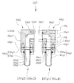
- the piping structure 107 of the seventh embodiment shown in FIG. 7 is a U-shaped piping used for changing the piping direction, and is composed of a right piping structure 107g1 and a left piping structure 107g2, and as shown in FIG.
- the pipe 15g2 constitutes a U-shaped pipe.
- the right piping structure 107g1 has the same configuration as the right piping structure 105e1 of the fifth embodiment shown in FIG. 5, and the left piping structure 107g2 is almost the same as the right piping structure 105e2 of the fifth embodiment shown in FIG. Therefore, detailed explanation is omitted.
- the right side pipe structure 107g1 of the pipe structure 107 is configured by connecting the pipe structure 30g1 to the joint 40g1 with the connection surface with the hexagon socket head bolt 19g1, and the left side pipe structure 107g2 is formed of the pipe structure 30g2 with the hexagon hole on the connection face joint 40g2. It is configured by connecting with attached bolts 19g2.
- the piping structure 107 is configured by joining the connection surface 41g1 and the connection surface 41g2 with a hexagon socket bolt 49g, the right piping structure 107g1 and the left piping structure 107g2.
- the pipe structure 107 is configured to make the pipe 15g1 in the same direction as the pipe 15g2 by coupling the joint with joint 40g1 and the joint with joint face 40g2, and the pipe 15e2 of the left side pipe structure 105e2 of the fifth embodiment shown in FIG. Is rotated in the direction of the pipe 15g1 of the pipe structure 107, and the flow path is formed into a U-shape.
- the interval between the pipes 15g1 and 15g2 piped in a U-shape is the smallest dimension which is the pitch of the two joint structures A20g1 and A20g2, and therefore, between the connection surface 41g1 and the connection surface 41g2. It can be adjusted by inserting an intermediate joint, and when it is necessary to add an angle to the arrangement of the tubes 15g1 and 15g2, it can be adjusted by inserting an angled spacer.
- the pipe structure 107 is an example in which one connection surface joint 40e2 of the fifth embodiment is rotated 180 degrees so that the pipe 15g1 and the pipe 15g2 are directed in the same direction. If the structure 107f1 and the left pipe structure 107f2 are combined, a stepped elbow pipe configuration can be obtained.
- the pipe structure 108 of the eighth embodiment shown in FIG. 8 is a U-shaped pipe used for changing the pipe direction, and is composed of a right side pipe structure 108h1 and a left side pipe structure 108h2, and as shown in FIG.
- the pipe 15h2 constitutes a U-shaped pipe.
- the right side pipe structure 108h1 has the same configuration as that of the right side pipe structure 106f1 of the sixth embodiment shown in FIG. 6, and the left side pipe structure 108h2 is substantially the same as the left side pipe structure 106f2.
- the pipe structure 30h1 is coupled to the joint 40h1 with a connection surface by a hexagon socket head bolt 19h1, and the right side pipe structure 108h1 is formed.
- the pipe structure 30h2 is coupled to the connection surface joint 40h2 by a hexagon socket head bolt 19h2.
- the piping structure 108 is configured by connecting the connection surface 41h1 and the connection surface 41h2 with a hexagon socket head bolt 49h and a hexagon socket head bolt 49Lh in the right side piping structure 108h1 and the left side piping structure 108h2.
- the pipe structure 108 is configured to make the pipe 15h1 and the pipe 15h2 in the same direction by coupling the joint 40h1 with connection surface and the joint 40h2 with connection surface, and the pipe 15f2 of the left side pipe structure 106f2 of the sixth embodiment shown in FIG. This is equivalent to a structure in which the flow path is rotated in the direction of the tube 15f1 to make the flow path U-shaped.
- the pipe 15h1 and the pipe 15h2 are piped in the same direction by the joint 40h1 with connection surface and the joint 40h2 with connection surface, and the interval is the pitch of the two joint structures A20h1, 40h2. It becomes a dimension.
- the interval between the pipes 15h1 and 15h2 piped in parallel is the smallest dimension which is the pitch of the two joint structures A20h1 and 40h2, so an intermediate joint is inserted between the connection surface 41h1 and the connection surface 41h2.
- the right side pipe structure 108h1 and the left side pipe structure 108h2 of the pipe structure 108 are combined, and the pipes 15h1 and 15h2 are made up of an L-shaped communication path L43h1, an L-type communication path L43h2, and a pipe 15h1 and a pipe 15h2. It has a smooth flow path that does not have irregularities on its inner surface, and does not accumulate contaminants or air.
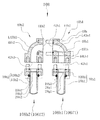
- the piping structure 109 according to the ninth embodiment shown in FIGS. 9A and 9B has an intermediate joint 34 interposed between the right side piping structure 109j1 and the pipe structure 30j2, and the pipe of the pipe structure 30j2 of the left side piping structure 109j2. 15j2 is changed to a predetermined exit angle.
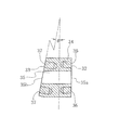
- the intermediate joint 34 is disposed around the passage 35 and the passage 35 having openings 35a and 35b that match the L-shaped communication passage L43j of the joint 40j with connection surface and the pipe structure 30j2 connection hole 24j2.
- a necessary angle ⁇ is provided between the intermediate connection surface 32 where the opening 35a opens and the intermediate connection surface 33 where the opening 35b opens.
- the intermediate joint 34 is manufactured at the factory by accurately measuring the angle ⁇ at the piping work site, and a hexagon socket head cap screw 19j passing through the connecting hole 44j of the connecting face joint 40j is screwed into the connecting hole 36.
- the bolts 19j2 with hexagonal holes that are passed through the connection holes 22j2 of the joint structure A20j2 of the pipe structure 30j2 are screwed into the connection holes 37 and fastened. It has the effect of piping at a matching angle.
- the piping structure 110 of the tenth embodiment shown in FIG. 10 is a U-shaped piping used for changing the piping direction, and is composed of a lower piping structure 110m1 and an upper piping structure 110m2, and a pipe 15m1 as shown.
- the pipe 15m2 constitutes a U-shaped pipe.
- the lower piping structure 110m1 has the same configuration as the right piping structure 104d of the fourth embodiment shown in FIG. 4, and similarly the upper piping structure 110m2 is similar to the right piping structure 104d of the fourth embodiment shown in FIG. Since it is almost the same, detailed description is omitted.
- the piping structure 110 is formed by inserting an intermediate joint 34m between the connection surface 41m1 of the joint 40m1 with the connection surface and the connection surface 41m2 of the joint 40m2 with the hexagon socket bolts 49m1, 49Lm1 and the hexagon socket bolts 49m2, 49Lm2. It is a fixed structure.
- the intermediate joint 34m of the tenth embodiment has substantially the same configuration as the intermediate joint 34 shown in FIG. 9B, a detailed description thereof will be omitted.
- Both the joints 40m1 and 40m2 with connecting surfaces of the intermediate joint 34m are provided with an L-shaped communication path L43m1 and an L-shaped communication path L43m2.
- end faces 32m and 33m of the intermediate joint 34m are provided with a screw hole connection hole 36m and a screw hole connection hole 37m concentrically with the passage 35m.
- the piping structure 110 is connected to the connecting holes 36m and 37m of the screw holes of the intermediate joint 34m with hexagon socket head bolts 49m1 and 49m2 and slightly longer hexagon socket head bolts 49Lm1 and 49Lm2, and the lower piping structure 110m1 and the upper piping structure 110m2. This is a fixed configuration.
- the piping structure 110 enables piping corresponding to the piping site by measuring and processing the separation dimensions of the pipes 15m1 and 15m2 at the piping site of the intermediate joint 34m.
- the intermediate joint 34m is preferably applied to a dimension in which the piping isolation dimension is longer than the total length of the screw hole connecting hole 36m and the screw hole connecting hole 37m.
- the upper piping structure 110m1 and the lower piping structure 110m2 of the piping structure 110 are combined, and the flow path constituted by the pipes 15m1 and 15m2, the L-shaped communication path L43m1, the communication path 35m, and the L-shaped communication path L43m2 is It has a smooth flow path that does not have irregularities on its inner surface, and does not accumulate contaminants or air.
- the piping structure 111 of the eleventh embodiment shown in FIG. 11 is a U-shaped piping used to change the piping direction, and is composed of a lower piping structure 111n1 and an upper piping structure 111n2, and a tube 15n1 as shown. And the tube 15n2 form a U-shaped pipe.
- the lower piping structure 111n1 has the same configuration as the right piping structure 102b of the second embodiment shown in FIG. 2, and the upper piping structure 111n2 is substantially the same as the right piping structure 104d of the fourth embodiment shown in FIG. Since they are the same, a detailed description is omitted.
- an intermediate joint 34n is inserted between the connection surface 42n1 of the joint 40n1 with the connection surface and the connection surface 42n2 of the joint 40n2 with the connection surface, and the intermediate joint 34n is inserted into the hexagon socket head bolt 49n and the hexagon socket head bolt. It is a structure fixed at 49Ln.
- the intermediate joint 34n of the eleventh embodiment is provided with a communication path 35n that communicates the elbow communication path L43n1 and the elbow communication path L43n2 of the joints 40n1 and 40n2 with connection surfaces.
- end faces 32n and 33n of the intermediate joint 34n are provided with through-hole connection holes 36n concentrically with the communication passage 35n.
- a hexagon socket head bolt 49n and a hexagon socket head bolt 49Ln are passed through the connection holes 44Ln1 and 44n2 of the through hole of the connection surface joint 40n2 and the through hole connection hole 36n of the intermediate joint 34n.
- the tip is coupled to the connecting hole 44n1 of the screw hole of the joint with connection surface 40n1, and the lower piping structure 111n1 and the upper piping structure 111n2 are fixed to the intermediate joint 34n.
- the piping structure 111 is capable of piping corresponding to the piping site by measuring and processing the separation dimension of the pipe 15n1 and the tube 15n2 at the piping site of the intermediate joint 34n.
- the intermediate joint 34n is preferably applied to a dimension in which the isolation dimension of the pipe is shorter than twice the length of the connection hole 44n1 of the screw hole.
- the lower piping structure 111n1 and the upper piping structure 111n2 are connected to each other, and the flow path constituted by the pipe 15n1, the L-shaped communication path L43n1, the L-shaped communication path L43n2, and the pipe 15n2 has an uneven portion on the inner surface. It has a smooth flow path that does not contain any contaminants or air.
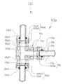
- the piping structure 112 of the twelfth embodiment shown in FIG. 13A is a T-shaped piping used for branching the piping direction, and the tee-type piping structure 112p constituting the piping structure 112 is a tee-type piping.
- the pipe structure 30p1 is fixed to the joint 40p1 with a connection surface with a hexagon socket head bolt 19p1, and the pipe structure 30p2 is fixed with a hexagon socket head bolt 19p2.
- the tee-type joint with connection surface 40p has a pipe structure 30p1, a pipe structure 30p2, and a tee-type communication passage T43p connected to the pipe structure 30p.
- the tee-type communication passage T43p is connected to the pipe 15p1 of the pipe structure 30p1, the pipe 15P2 of the pipe structure 30p2, and the pipe 15p of the pipe structure 30p, and branches the pipe structure 30p in two directions of the pipe 15p2 of the pipe structure 30p1.
- connection surface 42p to which the tube structure 30p of the joint 40p with connection surface is connected is the same as the connection surface 41 shown in FIG. 1 (f), and the connection surfaces 41p1 and 41p2 to which the tube structures 30p1 and 30p2 are connected are Since it is the same structure as the connection surface 42 shown in FIG.1 (e), detailed description is abbreviate
- the piping structure 112 includes a pipe structure 30p1 fixed to the connection surface 41p1 of the tee-type connection surface joint 40p of the piping structure 112p with a hexagonal socket bolt 19p1, and a pipe to the connection surface 41p2 of the tee-type connection surface joint 40p.
- the structure 30p2 is fixed with a hexagonal socket bolt 19p2, and the fluid flowing from the pipe 15p of the pipe structure 30p is branched into the pipe 15p1 and the pipe 15p2.
- the tee-type joint 40p with connection surface of the piping structure 112 of the twelfth embodiment having the above configuration, the pipe structure 30p1 connected to the joint 40p with connection surface, the pipe structure 30p2, and the pipe structure 30p are: It becomes a smooth flow path that does not have uneven portions on its inner surface, and does not store contaminants.
- the piping structure 113 of the thirteenth embodiment shown in FIG. 13 (b) is a multidirectional branching pipe used for connecting the lower piping structure 113u1 and the upper piping structure 113u2 to branch in multiple directions,
- the lower piping structure 113u1 and the upper piping structure 113u2 branching in multiple directions are substantially the same as the piping structure 112p described in the twelfth embodiment.
- the piping structure 113 of the thirteenth embodiment is formed by superimposing a joint with connection surface 40u1 and a joint with connection surface 40u2 constituting the lower piping structure 113u1 and the upper piping structure 113u2, and a lower connection surface 41u1 of the joint with connection surface 40u1.
- the pipe structure 30u3 is arranged on the upper side, and the pipe structure 30u4 is arranged on the upper connection surface 41u2 of the joint 40u2 with connection surface.
- the hexagonal socket bolt 49u is connected to the pipe structure 30u3 and the joint 40u1 with connection surface. It is a structure that is fastened by passing through the face-jointed joint 40u2 and connecting the tip thereof to the connection hole B22u3 of the screw hole of the tube structure 30u3.
- the piping structure 113 of the thirteenth embodiment having the above configuration branches the fluid flowing in from the pipe 15u1 of the pipe structure 30u1 connected to the piping structure 113u1 in three directions of the pipe 15u2 to the pipe 15u4.
- the flow path constituted by the pipe structures 30u1 to 30u4 of the pipe structure 113 of the thirteenth embodiment, the tee-type communication path T43u1, and the tee-type communication path T43u2 having the above-described configuration has a smooth surface with no irregularities on the inner surface. It becomes a simple flow path and does not store contamination.
- the piping structure 114 of the fourteenth embodiment shown in FIG. 14 (a) is a branched piping used for branching in multiple directions, and the piping structure 114r for branching a passage in multiple directions has a cross-type connection surface.
- the pipe structure 30r1 and the pipe structure 30r2 are fixed to the joint 40r with hexagon socket head bolts 19r1 and hexagon socket head bolts 19r2.
- the cross-type joint with connection surface 40r has a cross-type communication passage C43r connected to the pipe 15r1 of the pipe structure 30r1, the pipe 15r2 of the pipe structure 30r2, the pipe 15r3 of the pipe structure 30r3, and the pipe 15r4 of the pipe structure 30r4.
- the cross-type communication path C43r has a pipe structure 30r1 and a pipe structure 30r2 connected to one end of the cross-type communication path C43r, and a pipe structure 30r3 and a pipe structure 30r4 to the other end of the cross-type communication path C43r.
- the pipe 15r1 is connected and branches in three directions of a pipe 15r2, a pipe 15r3, and a pipe 15r4.
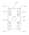
- connection surface 42r1 to which the pipe structure 30r1 of the joint 40r with connection surface is connected is the same square structure as the connection surface 42 in FIG. 1 (f), and the connection surface to which the pipe structure 30r2 of the joint 40r with connection surface is connected. 42r2 also has the same square structure as the connection surface 42 in FIG.
- connection surface 41r1 to which the pipe structure 30r3 is connected is arranged concentrically with the cross-type communication passage C43r as shown in FIG. 14B, and is a screw to which the hexagon socket bolt 19r1 of the pipe structure 30r1 is coupled. It has a rectangular configuration that includes a connecting hole 44r1 for a hole and that is longer by the depth of the connecting hole 45r formed in the connection surfaces 42r1 and 42r2.
- connection surface 41r2 is arranged concentrically with the cross-type communication passage C43r and includes a screw hole connection hole 44r2 to which the hexagon socket head bolt 19r4 of the tube structure 30r3 is coupled.
- This is a rectangular configuration that is longer by the depth of the connecting hole 45r1 formed in the surfaces 42r1 and 42r2.
- the pipe structure 30r1 is fixed to the connection surface 42r1 with the hexagon socket head bolt 19r1
- the pipe structure 30r2 is fixed to the connection surface 42r2 with the hexagon socket head bolt 19r2.
- the fluid flowing from the pipe 15r1 of the pipe structure 30r1 is branched in three directions of the pipe 15r2 to the pipe 15r4.
- the branch passage composed of the joint 40r with the connecting surface of the piping structure 114 of the fourteenth embodiment and the pipe structure 30r1 to the pipe structure 30ar4 connected to the joint 40r with the connecting surface has an uneven portion on the inner surface.
- the smooth flow path does not accumulate contaminants.
- the piping structure 115 of the fifteenth embodiment shown in FIG. 14 (c) is a multi-directional manifold piping used for connecting the lower piping structure 115s1 and the upper piping structure 115s2 and branching in multiple directions.
- the piping structures 115s1 and 115s2 branching in multiple directions have substantially the same configuration as the cross-branching piping structure 114r described in the fourteenth embodiment.
- connection surface joint 40s1 and the connection surface joint 40s2 constituting the piping structures 115s1 and 115s2 are overlapped to connect the lower surface of the connection surface joint 40s1.
- the pipe structure 30s5 is arranged on the surface 41s1, and the pipe structure 30s6 is arranged on the connection surface 41s2 on the upper surface of the joint with connection surface 40s2.
- the pipe structure 30s5 arranged below the piping structure 115s1 arranged as described above and the pipe structure 30s6 arranged above the piping structure 115s2 are configured such that the hexagonal bolt 49s is connected to the pipe structure 30s6, the connection surface joint 40s2, and the connection surface.
- the joint 40s1 is passed through and the tip of the joint 40s1 is coupled to the threaded connection hole B22s5 of the tube structure 30s5.
- the piping structure 115 having the above configuration branches the fluid flowing from the pipe 15s1 of the pipe structure 30s1 connected to the piping structure 115s1 in the five directions of the pipe 15s2 to the pipe 15s6.
- the piping structure 116 of the sixteenth embodiment shown in FIG. 15 is a multidirectional multi-way pipe used for connecting the lower piping structure 116t1 and the upper piping structure 116t2 to branch in multiple directions, and the passages in multiple directions. Branch.
- the piping structure 116 of the sixteenth embodiment shown in FIG. 15 is substantially the same as the piping structure 112p of the thirteenth embodiment shown in FIG. 116t2 has substantially the same configuration as the piping structure 114r of the twelfth embodiment shown in FIG.
- the pipe structure 116t1 and the joints 40t1 and 40t2 with the connection surface constituting the pipe structure 116t2 are overlapped, and the pipe structure 30t3 is disposed on the connection surface 41t1 on the lower surface of the joint 40t1 with the connection surface.
- the pipe structure 30t4 is disposed on the upper surface of the joint with connection surface 40t2, and the pipe structure 30t5 is fixed to the connection surface 42t2 of the joint with connection surface 40t2.
- a hexagon socket head bolt 49t passes through a joint 40t1 with a connection surface of the piping structure 116t1 and a joint 40t2 with a connection surface of the piping structure 116t2, and the tip of the screw hole of the pipe structure 30t3 It is configured by coupling to the coupling hole B22t3.
- the piping structure 116 having the above configuration branches the fluid flowing in from the pipe 15t1 of the pipe structure 30t1 connected to the piping structure 116t1 in four directions of the pipe 15t2 to the pipe 15t5.
- connection surface 41 of the L-shaped communication path L43b and the opening ends 43b1 and 43b2 of the connection surface 42 are It is cut so that the casting surface is smooth and the center can be specified accurately.
- Cutting of the open ends 43b1 and 43b2 of the connection surface 41b and the connection surface 42b of the above-mentioned L-shaped communication passage L43b is extremely small to the extent that there is no casting surface, and has a tapered shape with a small diameter from the open end to the back. is there.
- connection holes 44b and 45b provided in the connection surfaces 41b and 42b of the joint 40b with the connection surface according to the second embodiment shown in FIG. 2 are centered on the centers of the open ends 43b1 and 43b2 in which the casting surface is processed. It has been processed.
- the connecting surface to be connected is a through hole when one of the connecting holes is a screw hole, and the through hole is a slightly larger diameter than the screw hole (11 mm through hole for a 10 mm screw).
- the alignment of the open ends on the connecting surface to be connected is achieved by screwing a guide screw having a head slightly smaller in diameter than the connecting hole of the through hole into the connecting hole of the screw hole on the diagonal line of the four connecting holes.
- the connecting hole of the through hole is inserted through the screw so that the open ends of the two connecting surfaces are matched.
Landscapes
- Engineering & Computer Science (AREA)
- General Engineering & Computer Science (AREA)
- Mechanical Engineering (AREA)
- Branch Pipes, Bends, And The Like (AREA)
- Non-Disconnectible Joints And Screw-Threaded Joints (AREA)
- Flanged Joints, Insulating Joints, And Other Joints (AREA)
Description
13 隙間
14 先端
15 管
16 内径
17 端部
18 外周
19 六角孔付きボルト(ボルト)
A20 管継手(継手構造)
B20 管継手(継手構造)
A22 連結孔(通し孔またはネジ孔で構成する)
B22 連結孔(ネジ孔で構成する)
23 段部
231 管端挿入孔
24 接続孔
27 接続面
28 溶接部(溶着部)
29 溶着部
30 管構造
32 中間接続面
33 中間接続面
34 中間立体継手
35 通路35
36 連結孔(ネジ孔を構成する)
37 連結孔(ネジ孔を構成する)
39 オーリング
40 立体継手
41 接続面(第1接続面)
42 接続面(第2接続面)
43 連通通路
44 連結孔(第1連結孔)
45 連結孔(第2連結孔)
46 開口端(第1開口端)
47 開口端(第2開口端)
48 本体
A 隙間
L30 管構造の長さ
Claims (3)
- 作動油を流通させる通路を有する油圧機器のポート又は配管の継手等の接続体に接続される第1接続面と第2接続面と、
前記第1接続面に開口する第1開口端と、
前記第1接続面に開口し前記第1開口端と同心円上に配置した第1連結孔と、
前記第2接続面に開口する第2開口端と、
前記第2接続面に開口し前記第2開口端と同心円上に配置した第2連結孔と、
前記第1開口端と第2開口端を連通する連通通路と、
を備えた本体を有し、
前記本体の前記第1接続面を含む第1平面が前記第2接続面を含む第2平面と交差すると共に、前記第1接続面を第1開口端が中心にされた正方形とし、前記第2接続面を第2開口端が中心にされた正方形を含みその一辺が前記正方形一辺より前記第1連結孔の深さ以上の長さを付加した長さの長方形とした
ことを特徴とする接続面を備えた継手。 - 配管を構成する管と、
この管の端部が隙間を持って挿入される管端挿入孔とこの管端挿入孔に連設してあり前記管の内径相当の径を有する接続孔とこの接続孔が開口する接続面と備えた管継手と、
を備え、
前記管端挿入孔に挿入した前記管の端部の内面と前記接続孔の内面を溶着すると共に前記管の外周と前記管継手を溶接した
ことを特徴とする管継手を備えた管。 - 作動油を流通させる通路を有する油圧機器のポート又は配管の継手等の接続体に接続される第1接続面と第2接続面と、前記第1接続面に開口する第1開口端と、前記第1接続面に開口し前記第1開口端と同心円上に配置した第1連結孔と、前記第2接続面に開口する第2開口端と、前記第2接続面に開口し前記第2開口端と同心円上に配置した第2連結孔と、前記第1開口端と第2開口端を連通する連通通路と、を備えた本体を有し、前記本体の前記第1接続面を含む第1平面が前記第2接続面を含む第2平面と交差すると共に、前記第1接続面を第1開口端が中心にされた正方形とし、前記第2接続面を第2開口端が中心にされた正方形を含みその一辺が前記正方形一辺より前記第1連結孔の深さ以上の長さを付加した長さの長方形とした接続面を備えた継手と
配管を構成する管と、この管の端部が隙間を持って挿入される管端挿入孔とこの管端挿入孔に連設してあり前記管の内径相当の径を有する接続孔とこの接続孔が開口する接続面と備えた管継手と、を備え、前記管端挿入孔に挿入した前記管の端部の内面と前記接続孔の内面を溶着すると共に前記管の外周と前記管継手を溶接した管継手を備えた管と、
で構成し、
前記接続面を備えた継手の接続面と、前記管継手を備えた管の管継手をネジ結合により固定したこと特徴とする配管構造。
Priority Applications (4)
| Application Number | Priority Date | Filing Date | Title |
|---|---|---|---|
| EP13740657.5A EP2808590B1 (en) | 2012-01-24 | 2013-01-22 | Joint including connection surface and piping structure including same |
| CN201380006536.8A CN104081103B (zh) | 2012-01-24 | 2013-01-22 | 具有连接面的接头、具有管接头的管以及由它们构成的配管结构 |
| US14/374,149 US9976679B2 (en) | 2012-01-24 | 2013-01-22 | Joint including connection surface, pipe including pipe joint, and piping structure including same |
| KR1020147023420A KR101994244B1 (ko) | 2012-01-24 | 2013-01-22 | 접속면을 구비한 조인트, 관조인트를 구비한 관, 및 이들로 구성된 배관구조 |
Applications Claiming Priority (6)
| Application Number | Priority Date | Filing Date | Title |
|---|---|---|---|
| JP2012-012010 | 2012-01-24 | ||
| JP2012012010 | 2012-01-24 | ||
| JP2012-256318 | 2012-11-22 | ||
| JP2012256318 | 2012-11-22 | ||
| JP2013-008319 | 2013-01-21 | ||
| JP2013008319A JP5957387B2 (ja) | 2012-01-24 | 2013-01-21 | 接続面を備えた継手と管継手を備えた管及びそれらで構成した配管構造 |
Publications (1)
| Publication Number | Publication Date |
|---|---|
| WO2013111748A1 true WO2013111748A1 (ja) | 2013-08-01 |
Family
ID=48873468
Family Applications (1)
| Application Number | Title | Priority Date | Filing Date |
|---|---|---|---|
| PCT/JP2013/051194 Ceased WO2013111748A1 (ja) | 2012-01-24 | 2013-01-22 | 接続面を備えた継手と管継手を備えた管及びそれらで構成した配管構造 |
Country Status (6)
| Country | Link |
|---|---|
| US (1) | US9976679B2 (ja) |
| EP (1) | EP2808590B1 (ja) |
| JP (1) | JP5957387B2 (ja) |
| KR (1) | KR101994244B1 (ja) |
| CN (1) | CN104081103B (ja) |
| WO (1) | WO2013111748A1 (ja) |
Cited By (1)
| Publication number | Priority date | Publication date | Assignee | Title |
|---|---|---|---|---|
| JP2016027276A (ja) * | 2014-06-25 | 2016-02-18 | 出光興産株式会社 | 配管連通部材 |
Families Citing this family (15)
| Publication number | Priority date | Publication date | Assignee | Title |
|---|---|---|---|---|
| US10166618B2 (en) | 2016-01-15 | 2019-01-01 | International Business Machines Corporation | Heat stop for brazing or soldering |
| CN106240276A (zh) * | 2016-08-24 | 2016-12-21 | 奇瑞商用车(安徽)有限公司 | 一种后扭转梁焊接搭接结构 |
| KR101757773B1 (ko) * | 2016-10-18 | 2017-07-14 | 하진상 | 두께 확장 및 절삭 가공형 파이프를 이용한 조인트 플랜지 제조방법 |
| JP6913007B2 (ja) * | 2017-11-16 | 2021-08-04 | 株式会社神戸製鋼所 | 配管部材及び流体輸送装置 |
| US11162622B2 (en) * | 2018-04-27 | 2021-11-02 | Raytheon Technologies Corporation | Wedge adapter seal |
| DE102018208004A1 (de) * | 2018-05-18 | 2019-11-21 | Robert Bosch Gmbh | Hydraulisches System |
| CN110762311A (zh) * | 2018-07-26 | 2020-02-07 | 张家港中集圣达因低温装备有限公司 | 低温压力容器管道接入结构、制造方法和低温压力容器 |
| KR102669179B1 (ko) * | 2018-10-11 | 2024-05-27 | 에스케이온 주식회사 | 냉각 유로 커넥터 및 이를 구비하는 배터리 팩 |
| US11384876B2 (en) | 2020-07-07 | 2022-07-12 | Safoco, Inc. | Fluid conduit connector system |
| US11530601B2 (en) | 2020-07-07 | 2022-12-20 | Safoco, Inc. | Fluid conduit connector system |
| US11519536B2 (en) | 2020-07-07 | 2022-12-06 | Safoco, Inc. | Fluid conduit connector system |
| CN112594469B (zh) * | 2020-11-24 | 2022-06-28 | 中国人民解放军96901部队24分队 | 一种基于液压缸销轴的可变节流旋转接头 |
| CN112833268B (zh) * | 2020-12-31 | 2022-10-18 | 浙江永瑞气动有限公司 | 一种多功能气动管接头 |
| DE102021113617A1 (de) * | 2021-05-26 | 2022-12-01 | M-Tech Gmbh | Ventiladapter |
| CN115533442A (zh) * | 2022-11-10 | 2022-12-30 | 中国十九冶集团有限公司 | 联络管组焊固定装置 |
Citations (6)
| Publication number | Priority date | Publication date | Assignee | Title |
|---|---|---|---|---|
| JPS5836688U (ja) * | 1981-09-02 | 1983-03-10 | 大英フレックス工業株式会社 | ねじれ変位可能なベロ−ズ型伸縮管継手 |
| JPS61206187U (ja) * | 1985-06-14 | 1986-12-26 | ||
| JPS62179486U (ja) * | 1986-05-07 | 1987-11-14 | ||
| JPS6330686A (ja) * | 1986-07-21 | 1988-02-09 | 日本電信電話株式会社 | 気密構造 |
| JPH07103374A (ja) | 1993-10-07 | 1995-04-18 | Takuo Mori | フランジの構造及び該フランジに管を溶接固定する方法 |
| WO2010137138A1 (ja) * | 2009-05-27 | 2010-12-02 | 株式会社アドバンテスト | 配管継手、及びそれを備えたテストヘッド |
Family Cites Families (15)
| Publication number | Priority date | Publication date | Assignee | Title |
|---|---|---|---|---|
| US4080752A (en) * | 1975-05-01 | 1978-03-28 | Burge David A | Toy blocks with conduits and fluid seal means |
| JPS5836688A (ja) | 1981-08-26 | 1983-03-03 | 石川島播磨重工業株式会社 | 高速仕分パイリング方法 |
| US5709247A (en) * | 1995-12-15 | 1998-01-20 | Hutton; Peter B. | Multiple valve manifold for use with a pressure processing apparatus |
| US5845386A (en) * | 1996-08-30 | 1998-12-08 | Taper-Lok Corporation | Method for connecting a multiple-piece elbow assembly |
| US6467820B1 (en) * | 1998-10-23 | 2002-10-22 | David E. Albrecht | High-pressure fluid-flow system having compact two-bolt and four-bolt flanged and modular connectors |
| US7150475B2 (en) * | 2001-07-13 | 2006-12-19 | Talon Innovations, Inc. | Shear-resistant modular fluidic blocks |
| US7178556B2 (en) * | 2003-08-07 | 2007-02-20 | Parker-Hannifin Corporation | Modular component connector substrate assembly system |
| US20060022458A1 (en) * | 2004-07-27 | 2006-02-02 | Timothy Droste | Sealed fluid connector assembly |
| CN201007407Y (zh) * | 2007-02-16 | 2008-01-16 | 建湖县鸿达阀门管件有限公司 | 抗冲蚀管接头 |
| CN102031943A (zh) * | 2009-09-24 | 2011-04-27 | 江苏宏泰石化机械有限公司 | 一体化四通明杆平板阀 |
| JP5496773B2 (ja) | 2010-05-18 | 2014-05-21 | Ckd株式会社 | 薬液流路用連結装置 |
| US8544500B2 (en) | 2010-05-18 | 2013-10-01 | Ckd Corporation | Coupling apparatus for chemical fluid flow channel |
| CN201803015U (zh) * | 2010-09-03 | 2011-04-20 | 泉州市丰泽区东方机械有限公司 | 一种热熔胶输送管道连接头 |
| CN101985925A (zh) | 2010-12-06 | 2011-03-16 | 中国石油集团西部钻探工程有限公司 | 耐用钻井泵 |
| CN201902194U (zh) * | 2010-12-25 | 2011-07-20 | 海城市石油机械制造有限公司 | 油气井节流管汇 |
-
2013
- 2013-01-21 JP JP2013008319A patent/JP5957387B2/ja active Active
- 2013-01-22 US US14/374,149 patent/US9976679B2/en not_active Expired - Fee Related
- 2013-01-22 CN CN201380006536.8A patent/CN104081103B/zh not_active Expired - Fee Related
- 2013-01-22 EP EP13740657.5A patent/EP2808590B1/en not_active Not-in-force
- 2013-01-22 KR KR1020147023420A patent/KR101994244B1/ko not_active Expired - Fee Related
- 2013-01-22 WO PCT/JP2013/051194 patent/WO2013111748A1/ja not_active Ceased
Patent Citations (6)
| Publication number | Priority date | Publication date | Assignee | Title |
|---|---|---|---|---|
| JPS5836688U (ja) * | 1981-09-02 | 1983-03-10 | 大英フレックス工業株式会社 | ねじれ変位可能なベロ−ズ型伸縮管継手 |
| JPS61206187U (ja) * | 1985-06-14 | 1986-12-26 | ||
| JPS62179486U (ja) * | 1986-05-07 | 1987-11-14 | ||
| JPS6330686A (ja) * | 1986-07-21 | 1988-02-09 | 日本電信電話株式会社 | 気密構造 |
| JPH07103374A (ja) | 1993-10-07 | 1995-04-18 | Takuo Mori | フランジの構造及び該フランジに管を溶接固定する方法 |
| WO2010137138A1 (ja) * | 2009-05-27 | 2010-12-02 | 株式会社アドバンテスト | 配管継手、及びそれを備えたテストヘッド |
Cited By (1)
| Publication number | Priority date | Publication date | Assignee | Title |
|---|---|---|---|---|
| JP2016027276A (ja) * | 2014-06-25 | 2016-02-18 | 出光興産株式会社 | 配管連通部材 |
Also Published As
| Publication number | Publication date |
|---|---|
| KR101994244B1 (ko) | 2019-09-30 |
| EP2808590A4 (en) | 2015-11-04 |
| EP2808590A1 (en) | 2014-12-03 |
| JP2014122692A (ja) | 2014-07-03 |
| EP2808590B1 (en) | 2017-08-09 |
| US20140367960A1 (en) | 2014-12-18 |
| US9976679B2 (en) | 2018-05-22 |
| KR20140116215A (ko) | 2014-10-01 |
| CN104081103B (zh) | 2016-12-21 |
| CN104081103A (zh) | 2014-10-01 |
| JP5957387B2 (ja) | 2016-07-27 |
Similar Documents
| Publication | Publication Date | Title |
|---|---|---|
| JP5957387B2 (ja) | 接続面を備えた継手と管継手を備えた管及びそれらで構成した配管構造 | |
| EP2957805B1 (en) | Bolted flange fitting assembly for double wall tube | |
| JP6031032B2 (ja) | ウエルドレスアルミニウム製hvacシステム | |
| FI115485B (fi) | Putkiston haarakappale | |
| US6953048B2 (en) | Modular surface-mount fluid-flow system | |
| TWI603023B (zh) | 模組化接頭及製造此接頭的方法 | |
| JP2016223633A (ja) | 配管継手を用いた配管システム | |
| EP3887704B1 (en) | Universal tube stub plug with seal port | |
| JP2012026483A (ja) | 配管接続構造 | |
| JP2014145553A (ja) | 二重管式熱交換器 | |
| US6546898B1 (en) | Hydronic heating system and kit | |
| CN100385165C (zh) | 管接头法兰 | |
| JP5996238B2 (ja) | 配管継手及びこれを用いた配管システム | |
| AU2020355421B2 (en) | Method for producing a pipeline arrangement, and pipeline arrangement | |
| KR100740166B1 (ko) | 바이패스관의 구조 | |
| JP5270712B2 (ja) | 組み立て式マニフォールド | |
| EP3394492B1 (en) | A fitting assembly for corrugated tubing | |
| KR200389186Y1 (ko) | 배관이음구 | |
| TWI832558B (zh) | 組合式法蘭夾片 | |
| KR200432867Y1 (ko) | 스테인리스관 연결방식 | |
| HK1058548B (en) | Modular surface-mount fluid-flow system | |
| JP2000257784A (ja) | 各種機器との接続部を備えた管継手 | |
| WO2015193496A1 (en) | Poppet valve arrangement |
Legal Events
| Date | Code | Title | Description |
|---|---|---|---|
| 121 | Ep: the epo has been informed by wipo that ep was designated in this application |
Ref document number: 13740657 Country of ref document: EP Kind code of ref document: A1 |
|
| WWE | Wipo information: entry into national phase |
Ref document number: 14374149 Country of ref document: US |
|
| NENP | Non-entry into the national phase |
Ref country code: DE |
|
| ENP | Entry into the national phase |
Ref document number: 20147023420 Country of ref document: KR Kind code of ref document: A |
|
| REEP | Request for entry into the european phase |
Ref document number: 2013740657 Country of ref document: EP |
|
| WWE | Wipo information: entry into national phase |
Ref document number: 2013740657 Country of ref document: EP |