WO2013111765A1 - Borne de raccordement électrique et connecteur utilisant une telle borne - Google Patents
Borne de raccordement électrique et connecteur utilisant une telle borne Download PDFInfo
- Publication number
- WO2013111765A1 WO2013111765A1 PCT/JP2013/051251 JP2013051251W WO2013111765A1 WO 2013111765 A1 WO2013111765 A1 WO 2013111765A1 JP 2013051251 W JP2013051251 W JP 2013051251W WO 2013111765 A1 WO2013111765 A1 WO 2013111765A1
- Authority
- WO
- WIPO (PCT)
- Prior art keywords
- contact
- terminal
- lock member
- connector
- movement
- Prior art date
- Legal status (The legal status is an assumption and is not a legal conclusion. Google has not performed a legal analysis and makes no representation as to the accuracy of the status listed.)
- Ceased
Links
Images




Classifications
-
- H—ELECTRICITY
- H01—ELECTRIC ELEMENTS
- H01R—ELECTRICALLY-CONDUCTIVE CONNECTIONS; STRUCTURAL ASSOCIATIONS OF A PLURALITY OF MUTUALLY-INSULATED ELECTRICAL CONNECTING ELEMENTS; COUPLING DEVICES; CURRENT COLLECTORS
- H01R12/00—Structural associations of a plurality of mutually-insulated electrical connecting elements, specially adapted for printed circuits, e.g. printed circuit boards [PCB], flat or ribbon cables, or like generally planar structures, e.g. terminal strips, terminal blocks; Coupling devices specially adapted for printed circuits, flat or ribbon cables, or like generally planar structures; Terminals specially adapted for contact with, or insertion into, printed circuits, flat or ribbon cables, or like generally planar structures
- H01R12/70—Coupling devices
- H01R12/71—Coupling devices for rigid printing circuits or like structures
- H01R12/712—Coupling devices for rigid printing circuits or like structures co-operating with the surface of the printed circuit or with a coupling device exclusively provided on the surface of the printed circuit
- H01R12/716—Coupling device provided on the PCB
-
- H—ELECTRICITY
- H01—ELECTRIC ELEMENTS
- H01R—ELECTRICALLY-CONDUCTIVE CONNECTIONS; STRUCTURAL ASSOCIATIONS OF A PLURALITY OF MUTUALLY-INSULATED ELECTRICAL CONNECTING ELEMENTS; COUPLING DEVICES; CURRENT COLLECTORS
- H01R12/00—Structural associations of a plurality of mutually-insulated electrical connecting elements, specially adapted for printed circuits, e.g. printed circuit boards [PCB], flat or ribbon cables, or like generally planar structures, e.g. terminal strips, terminal blocks; Coupling devices specially adapted for printed circuits, flat or ribbon cables, or like generally planar structures; Terminals specially adapted for contact with, or insertion into, printed circuits, flat or ribbon cables, or like generally planar structures
- H01R12/70—Coupling devices
- H01R12/82—Coupling devices connected with low or zero insertion force
- H01R12/85—Coupling devices connected with low or zero insertion force contact pressure producing means, contacts activated after insertion of printed circuits or like structures
- H01R12/88—Coupling devices connected with low or zero insertion force contact pressure producing means, contacts activated after insertion of printed circuits or like structures acting manually by rotating or pivoting connector housing parts
-
- H—ELECTRICITY
- H01—ELECTRIC ELEMENTS
- H01R—ELECTRICALLY-CONDUCTIVE CONNECTIONS; STRUCTURAL ASSOCIATIONS OF A PLURALITY OF MUTUALLY-INSULATED ELECTRICAL CONNECTING ELEMENTS; COUPLING DEVICES; CURRENT COLLECTORS
- H01R13/00—Details of coupling devices of the kinds covered by groups H01R12/70 or H01R24/00 - H01R33/00
- H01R13/02—Contact members
- H01R13/10—Sockets for co-operation with pins or blades
- H01R13/11—Resilient sockets
- H01R13/114—Resilient sockets co-operating with pins or blades having a square transverse section
Definitions
- the present invention relates to an electrical connection terminal used for a connector for connecting a circuit board, a cable, or the like of various electrical devices, and a connector using the same.
- an electrical connection terminal used in this type of connector a contact portion that is electrically connected to a connection object by being pressed from a predetermined direction perpendicular to the insertion / removal direction to a connection object that is inserted / removed in a predetermined direction;
- a thing provided with the movement regulation part which regulates the movement to the extraction direction of a connection target object by press-contacting to a connection target object from the same direction or the opposite direction as a contact part is known (for example, refer to patent documents 1). ).
- the movement restricting portion extends obliquely so as to form an acute angle with the proximal end side of the connection object with respect to the insertion / extraction direction of the connection object, and the connection object whose distal end tends to move in the removal direction It is formed to bite into things.
- the contact pressure of the movement control part with respect to a connection target object is with respect to a connection target object. It occurs in the contact direction of the contact portion, and the contact pressure of the movement restricting portion affects the contact pressure of the contact portion. That is, when the movement restricting portion is pressed against the connection object from the same direction as the contact portion, the contact pressure of the contact portion decreases due to the contact pressure of the movement restricting portion, resulting in poor contact between the connection object and the contact portion. There was a problem that it became easy.
- connection object is scratched on the same contact surface as the contact part by the movement restricting part, there is a problem that a contact failure between the contact part and the connection object is liable to occur due to the scratch.
- the contact pressure of the contact part increases due to the contact pressure of the movement restricting part, which increases the insertion resistance of the connection object and is incomplete. There was a problem that insertion was likely to occur.
- the present invention has been made in view of the above problems, and an object of the present invention is to provide an electrical connection terminal that does not reduce or increase the contact pressure of the contact portion due to the contact pressure of the movement restricting portion with respect to the connection object. And providing a connector using the same.
- the present invention provides a contact portion that is electrically connected to an object to be connected by being pressed from a predetermined direction perpendicular to the insertion / removal direction to a connection object that is inserted / removed in a predetermined direction,
- a movement regulating unit that regulates movement of the connection object in the removal direction by pressing the connection object from another direction that does not generate a reaction force in the contact direction of the contact part among the directions orthogonal to the direction.
- the movement restricting portion is pressed against the mating terminal from the direction in which the reaction force in the contact direction of the contact portion does not occur, so the contact pressure of the movement restricting portion is not applied in the contact direction of the contact portion, and the movement restricting portion
- the contact pressure of the contact portion does not reduce or increase the contact pressure of the contact portion.
- the contact pressure of the contact portion does not decrease or increase due to the contact pressure of the movement restricting portion, the contact failure between the connection object and the contact portion due to the decrease of the contact pressure of the contact portion is prevented.
- the scratch of the connection object is not formed on the same contact surface as the contact portion. It is also possible to prevent poor contact with the device.
- the front side perspective view of the connector which shows one Embodiment of this invention
- Front side perspective view of connector showing a state where first lock member is rotated.
- Front side perspective view of connector showing a state in which first and second lock members are rotated.
- FIG. 1 to FIG. 27 show an embodiment of the present invention, and show connectors mounted on circuit boards of various electric devices.
- This connector is mounted on one substrate 1 of a pair of substrates connected to each other, and is connected to a plurality of counterpart terminals 3 as connection objects attached to the other substrate (not shown). It has become.
- the connector of this embodiment includes a connector body 10 into which the mating terminal 3 is inserted from below, a plurality of terminals 20 whose contact portions with the mating terminal 3 can be displaced in the insertion / extraction direction of the mating terminal 3, and a connector body. 10, a movable member 30 movably provided in the insertion / removal direction of the mating terminal 3, a first lock member 40 capable of restricting displacement of the contact portion of the terminal 20, and rotation of the terminal lock member 40 can be restricted. And a second locking member 50.
- the connector body 10 is made of a synthetic resin molded product and is arranged on the substrate 1.
- the connector main body 10 includes a main body portion 11 formed so as to cover a front surface, a back surface, and both side surfaces of a lower portion thereof, and a pair of side wall portions 12 erected upward from both sides in the width direction of the main body portion 11.
- Metal fixing members 13 that are fixed to the substrate 1 are attached to both side surfaces of the main body 11.
- the main body 11 is formed in a hollow shape so as to penetrate in the vertical direction, and the movable member 30 is arranged in the main body 11 so as to be movable in the vertical direction.
- a plurality of groove-shaped terminal holding portions 14 for holding the respective terminals 20 are provided on the back surface of the main body portion 11, and the respective terminal holding portions 14 are arranged at intervals in the width direction.
- Each side wall 12 extends upward from the rear end side of the main body 11 and is formed so that its upper portion extends forward, and the first lock member 40 and the second lock member 50 are rotated. Supports freely.
- a first rotation support portion 12a that rotatably supports the first lock member 40 is provided on the outer surface of each side wall portion 12 in the width direction, and a first lock member is provided above the first rotation support portion 12a.
- a first protrusion 12b for holding 40 in a predetermined rotation position is provided.
- a second rotation support portion 12 c that rotatably supports the second lock member 50 is projected, and below the second rotation support portion 12 c.
- a second protrusion 12d for holding the lock member 50 at a predetermined rotational position is provided.
- Each terminal 20 is formed by bending a metal plate, and is held by the connector body 10 at a distance from each other.
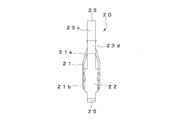
- the terminal 20 can be elastically deformed in the insertion / extraction direction of the mating terminal 3 between the contact part 21 electrically connected to the mating terminal 3, the fixing part 22 fixed to the connector body 10, and the contact part 21 and the fixing part 22.
- the contact portion 21 has a pair of contact piece portions 21 a facing in the width direction of the terminal 20 and a U-shaped fixed portion 21 b fixed to the movable member 30, and each contact piece portion 21 a is the counterpart terminal 3.
- the terminal 20 is in pressure contact with the width direction of the terminal 20 (direction (X direction in FIG. 16) orthogonal to the insertion / extraction direction of the mating terminal 3 (Z direction in FIG. 16)).
- the contact piece portions 21a are formed such that they approach each other from the lower end side toward the upper end side, and the upper end sides are bent in opposite directions, and the counterpart terminal 3 is connected to the terminal 20 by the portion closest to each other. It is designed to be clamped from the width direction.
- the fixing portion 21b includes a front surface portion 21b-1 and a pair of side surface portions 21b-2 in the width direction, and is formed so that the mating terminal 3 can be inserted between the side surface portions 21b-2 in the vertical direction.
- each contact piece portion 21a extends upward from the upper end of each side surface portion 21b-2.
- the fixing portion 22 has a protrusion 22 a that is locked to the connector main body 10, and the protrusion 22 a is locked to the terminal holding portion 14 by being press-fitted in the vertical direction into the terminal holding portion 14 of the connector main body 10. Are fixed to the terminal holding portion 14.
- the movable portion 23 includes a first elastic piece portion 23a extending from the fixed portion 21b of the contact portion 21 toward the upper side (insertion direction of the counterpart terminal 3) and the rear side (the counterpart terminal 3) so as to bypass the contact portion 21.
- a second elastic piece 23b extending in the direction orthogonal to the insertion / extraction direction), and a third elastic piece 23b extending from the second elastic piece 23b downward (in the direction in which the mating terminal 3 is pulled out) toward the fixed portion 22 side.
- the third elastic piece portion 23c is provided with a U-shaped bent portion 23d which is bent in the vertical direction.
- the movement restricting portion 24 is provided in the fixing portion 21b of the contact portion 21, and is formed by raising the front surface portion 21b-1 of the fixing portion 21b into the fixing portion 21b.
- the movement restricting portion 24 extends obliquely upward toward the rear so as to form an acute angle with the base end side of the counterpart terminal 3 with respect to the vertical direction (insertion / extraction direction of the counterpart terminal 3), and moves in the extraction direction. It is formed so that the tip bites into the connection object.
- the movement restricting portion 24 is connected to the other side from the direction (front-rear direction of the terminal 20 (Y direction in FIG. 16)) orthogonal to the contact direction of the contact portion 21 (width direction of the terminal 20 (X direction in FIG. 16)) It comes in contact with the terminal 3.
- the connecting portion 25 extends to the lower end of the fixed portion 22 and is bent in an L shape toward the rear.
- the movable member 30 is made of a synthetic resin molded product, and is disposed in the main body 11 of the connector main body 10 so as to be movable in the vertical direction.
- the movable member 30 is provided with a holding hole 31 that holds the contact portion 21 side of each terminal 20.
- the contact portion 21 of each terminal 20 is fixed to the movable member 30 by press-fitting a fixing portion 21 b into the holding hole 31.
- the bottom surface of the holding hole 31 is provided with a plurality of insertion ports 31a into which the mating terminals 3 are inserted, and the mating terminal 3 inserted upward from the insertion port 31a passes through the fixing portion 21b of the terminal 20.
- the contact portions 21 are pressed against the mating terminal 3 by being sandwiched between the contact piece portions 21 a while spreading the contact piece portions 21 a of the contact portion 21. Further, on both side surfaces of the movable member 30 in the width direction, engaging portions 32 that engage with the first lock member 40 protrude.
- the first lock member 40 is made of a synthetic resin molded product and is rotatably supported on each side wall portion 12 of the connector main body 10.
- the first locking member 40 is formed so as to extend in the width direction of the connector main body 10, and side portions 41 disposed on the outer sides in the width direction of the side wall portions 12 are provided at both ends in the width direction.
- the side surface portion 41 is provided with a rotation hole 41a that is rotatably engaged with the first rotation support portion 12a of the side wall portion 12, and the first lock member 40 attaches the first rotation support portion 12a to the first rotation support portion 12a. It is designed to rotate around the center.
- the side surface portion 41 is provided with two holes 41b and 41c that can be engaged with the first protrusion 12b of the side wall portion 12 at intervals in the rotational direction of the first lock member 40, as shown in FIG.
- first lock member 40 When the first lock member 40 is positioned at the first rotation position (first operation position), the first protrusion 12b is engaged with the one hole 41b, and the first lock member 40 is 1 is held at the rotational position. Further, as shown in FIG. 20, when the first lock member 40 is rotated forward to the second rotation position (second operation position), the first protrusion 12b is engaged with the other hole 41c, The first lock member 40 is held in the second rotation position.
- the side surface portion 41 is provided with an engagement hole 41 d as an engagement portion that engages with the engagement portion 32 of the movable member 30.
- the engagement hole 41d includes a first hole 41d-1 that engages so as to restrict the movement of the engagement portion 32 of the movable member 30 in the vertical direction (the insertion / removal direction of the counterpart terminal 3), and the engagement portion And a second hole portion 41d-2 that engages 32 movably in the vertical direction.
- the first hole portion 41d-1 is formed so as to extend in the rotational direction of the first lock member 40, and the width of the engaging portion 32 with respect to the moving direction is substantially equal to the outer diameter of the engaging portion 32. Is formed.
- the second hole portion 41d-2 is formed so as to extend in the moving direction of the engaging portion 32, and is formed so that the length of the engaging portion 32 in the moving direction is longer than the outer diameter dimension of the engaging portion 32.
- the engagement hole 41d is formed so that one end of the first hole 41d-1 communicates with the center in the longitudinal direction of the second hole 41d-2, and as shown in FIG.
- first lock member 40 is provided with a locking portion 42 that locks the second lock member 50.
- the locking portion 42 protrudes from the upper end of the side surface portion 41, and is formed so as to have a gentle inclination from the top portion 42 a to one rotation direction side of the first lock member 40. Further, the other rotation direction side of the first lock member 40 from the top portion 42a of the locking portion 42 is formed so as to form a vertical step toward the first rotation support portion 12a.
- An operation portion 43 for rotating the first lock member 40 is provided on the center side in the width direction of the first lock member 40. The operation portion 43 is located above the closed first lock member 40. It is formed so as to protrude.
- the second lock member 50 is made of a synthetic resin molded product and is rotatably supported on each side wall portion 12 of the connector main body 10.
- the second lock member 50 extends in the width direction of the connector main body 10 and is formed in a plate shape that can open and close the upper surface of the connector main body 10, and rotates in one direction of rotation (operation direction) as shown in FIG. Then, the upper surface of the connector main body 10 is closed, and as shown in FIG. 21, the upper surface of the connector main body 10 is closed when the connector main body 10 is rotated in the rotation direction (operation direction).
- connection portions 51 that are connected to the side wall portions 12 are respectively provided.
- Each connecting portion 51 is formed on the rear end side of the second lock member 50 so as to extend toward the connector main body 10, and is disposed on the outer side in the width direction of each side wall portion 12.
- the connecting portion 51 is provided with a rotation hole 51a that is rotatably engaged with the second rotation support portion 12c of the side wall portion 12, and the second lock member 50 connects the second rotation support portion 12c. It is designed to rotate around the center.
- the connecting portion 51 is provided with a recess 51b that can be engaged with the second protrusion 12d of the side wall portion 12.
- the second lock member 50 is rotated to the closed position as shown in FIG. 12d is engaged with the recess 51b, and the second lock member 50 is held in the closed position.
- the second protrusion 12d is formed to protrude in a spherical shape, and as shown in FIG. 26, the second lock member 50 rotates from the closed position toward the open position.
- the edge 51c of the recess 51b climbs over the top of the second protrusion 12d while elastically deforming the connecting portion 51 toward the outer side in the width direction of the second lock member 50, so that FIG.
- the second lock member 50 is rotated to the open position.
- the restoring force of the connecting portion 51 and the inclined surface (spherical surface) of the second protrusion 12d until the edge 51c of the recess 51b gets over the top of the second protrusion 12d.
- the edge 51c of the recess 51b tends to be returned to the original position as shown by the broken line arrow in the drawing, and the urging force in the closing direction is generated in the second lock member 50.
- FIG. 26 the restoring force of the connecting portion 51 and the inclined surface (spherical surface) of the second protrusion 12d until the edge 51c of the recess 51b gets over the top of the second protrusion 12d.
- each locking portion 52 is provided on the second lock member 50. It is arranged on the front end side.
- the locking portion 52 protrudes toward the side surface portion 41 of the first locking member 40, and the front end side of the top portion 52a of the locking portion 52 is directed toward the first rotation support portion 12a in the closed position. It is formed so as to form a vertical step. Further, the rear end side from the top portion 52a of the locking portion 52 is formed to have a gentle inclination.
- the upper surface of the second lock member 50 is formed so as to form a horizontal plane at the closed position, and in a part thereof (a part other than the width direction both ends and the rear end), a recess that is lower than the other parts. 53 is formed.
- a plurality of partition portions 54 extending in the front-rear direction are projected from the lower surface of the second lock member 50, and each partition portion 54 is positioned between the movable portions 23 of the terminals 20 when the second lock member 50 is closed. It is supposed to be.
- operation portions 55 for rotating the second lock member 50 are provided on both ends in the width direction of the second lock member 50, and each operation portion 55 is a second lock member in a closed state. 50 is formed so as to protrude upward.
- the connector configured as described above is disposed on the upper surface of the substrate 1 as shown in FIG. 17, and the fixing members 13 of the connector main body 10 and the connection portions 25 of the terminals 20 are soldered to the substrate 1. At that time, the upper surface of the closed second lock member 50 (behind the recessed portion 53) is sucked by the suction nozzle for conveying the component, so that it is transported and mounted on the substrate 1.
- the substrate 1 is provided with a plurality of insertion holes 1 a for inserting the counterpart terminals 3.
- the mating terminal 3 is inserted into the connector main body 10 from below the substrate 1 through the insertion hole 1a. It is connected to the terminal 20 inside.
- a plurality of counterpart terminals 3 are provided at equal intervals to each terminal 20 and attached to the other substrate (not shown).
- the first lock member 40 When connecting the counterpart terminal 3, the first lock member 40 is rotated to the first rotation position as shown in FIGS. 6 and 17. Accordingly, the engaging portion 32 of the movable member 30 is positioned in the first hole portion 41d-1 of the engaging hole 41d of the first lock member 40, and the movable member 30 is moved in the vertical direction (insertion / removal of the mating terminal 3). Direction) is restricted.
- the mating terminal 3 is inserted into the connector main body 10
- the mating terminal 3 passes through the fixed portion 21 b of the terminal 20 through the insertion port 31 a of the movable member 30, and each contact piece of the contact portion 21.
- the contact part 21 a is clamped between the contact piece parts 21 a while spreading the part 21 a, and the contact part 21 is pressed against the counterpart terminal 3, whereby the counterpart terminal 3 is connected to the terminal 20.
- the contact portion 21 of the terminal 20 is restricted by the first locking member 40 together with the movable member 30 from moving in the insertion / removal direction of the counterpart terminal 3, so that the contact pressure between the terminal 20 and the counterpart terminal 3 Even if the insertion force of the counterpart terminal 3 is generated in the contact portion 21 of the terminal 20, the contact portion 21 of the terminal 20 is not displaced in the insertion direction of the counterpart terminal 3.
- the movement restricting portion 24 of the terminal 20 comes into contact with the counterpart terminal 3, and the movement restricting portion 24 restricts movement of the counterpart terminal 3 in the removal direction. .
- the movement restricting portion 24 is in pressure contact with the mating terminal 3 from a direction (Y direction in FIG. 16) orthogonal to the contact direction (X direction in FIG. 16) of the contact portion 21, and therefore the contact of the movement restricting portion 24.
- the pressure is not applied in the contact direction of the contact portion 21. Thereby, the contact pressure of the contact part 21 is not reduced or increased by the contact pressure of the movement restricting part 24.
- the first lock member 40 is rotated to the second rotation position as shown in FIGS.
- the first lock member 40 can be rotated by pressing the operation portion 42 of the first lock member 40 in the rotation direction while putting the fingertip into the recess 53 on the upper surface of the second lock member 50. It becomes easy.
- the engagement portion 32 of the movable member 30 is moved from the first hole portion 41d-1 of the engagement hole 41d of the first lock member 40 to the second position. Movement of the movable member 30 in the vertical direction (insertion / removal direction of the mating terminal 3) is released.
- the engaging portion 32 of the movable member 30 can move in the second hole 41d-2 in the vertical direction, so that the contact portion 21 of the terminal 20 moves in the insertion / extraction direction of the counterpart terminal 3 together with the movable member 30. It becomes possible to move.
- the movable portion 23 of the terminal 20 is elastically deformed, thereby moving the movable member.
- 30 and the contact portion 21 of the terminal 20 are displaced together with the mating terminal 3 in the insertion / extraction direction of the mating terminal 3, and the positional deviation between the substrates is absorbed.
- the movable portion 23 of the terminal 20 extends from the contact portion 21 side in the insertion direction of the mating terminal 3, and the fixing portion 22 toward the extraction direction of the mating terminal 3 so as to bypass the contact portion 21. Since it is formed to extend to the side, the displacement of the contact portion 21 can be increased without forming the movable portion 23 long in the insertion / extraction direction of the mating terminal 3.
- the movable portion 23 is also elastically deformed in the insertion / extraction direction of the mating terminal 3 by the bent portion 23d of the third elastic piece portion 23c.
- the connecting portion 51 is elastically moved outward in the width direction of the second lock member 50. While the edge 51c of the recess 51b tries to get over the top of the second protrusion 12d while being deformed, the top 42a of the locking portion 42 of the first locking member 40 is locked to the locking portion 52 of the second locking member 50. When climbing over the top, the edge 51c of the recess 51b does not reach the top of the second protrusion 12d.
- the first lock member 40 When the first lock member 40 is rotated to the second rotation position as described above, the first lock member 40 is rotated to the first rotation position by the engagement of the engagement portions 42 and 52. Movement is regulated.
- the second lock member 50 is manually rotated in the opening direction, and the engaging portion 42 of the first lock member 40 is rotated. And the locking portion 52 of the second lock member 50 are released.
- the edge 51c of the recess 51b gets over the top of the second protrusion 12d as shown in FIG. The urging force that the edge 51c of 51b tries to return to the original position is not generated.
- the recess 51b that has climbed over the top of the second protrusion 12d toward the opening direction of the second locking member 50 is the top of the second protrusion 12d unless the second locking member 50 is rotated in the closing direction. Therefore, the second lock member 50 is held closer to the opening direction than the rotational position P.
- the rotation position P is a position where the locking portion 42 of the first lock member 40 and the locking portion 52 of the second lock member 50 are not locked to each other. Thereby, even if it does not hold
- the second lock member 50 is rotated in the closing direction, and a force is applied in the closing direction to apply the second protrusion 12d.
- a force is applied in the closing direction to apply the second protrusion 12d.
- the counterpart terminal 3 since the first locking member 40 capable of restricting the displacement of the contact portion 21 of the terminal 20 in the insertion / extraction direction of the counterpart terminal 3 is provided, the counterpart terminal 3 is connected.
- the first locking member 40 restricts the displacement of the contact portion 21 of the terminal 20
- the insertion force of the counterpart terminal 3 into the contact portion 21 of the terminal 20 due to the contact pressure between the terminal 20 and the counterpart terminal 3 is obtained.
- the counterpart terminal 3 can be connected without displacing the contact portion 21 of the terminal 20 in the insertion direction of the counterpart terminal 3.
- the contact part 21 of the terminal 20 does not remain in the state displaced in the insertion direction of the other party terminal.
- the displacement restriction of the contact portion 21 of the terminal 20 by the first lock member 40 is released, so that the contact portion 21 of the terminal 20 moves in the insertion / extraction direction of the mating terminal 3. Therefore, even if the counterpart terminal 3 is displaced in the insertion / extraction direction due to, for example, bending of the substrate or external vibration, the contact portion 21 of the terminal 20 together with the counterpart terminal 3 is inserted / extracted. It is possible to absorb displacement and vibration between the substrates. At that time, since the terminal 20 is connected to the counterpart terminal 3 without displacing the contact portion 21 in the insertion / extraction direction of the counterpart terminal 3, the movable range of the contact portion 21 is set in the insertion direction and extraction of the counterpart terminal 3.
- any of the directions can be sufficiently secured, and the displacement of the mating terminal 3 due to the bending or vibration of the substrate can be reliably absorbed.
- the contact part 21 does not displace in the insertion / extraction direction of the other party terminal 3 at the time of connection, the fitting length (length from the front-end
- the first lock member 40 is rotatably provided on the connector main body 10 and the first lock member 40 is rotated to a predetermined first rotation position, the displacement of the contact portion 21 is restricted, and the first lock member 40 is controlled.
- the lock member 40 is rotated to the second rotation position, the displacement restriction to the contact portion 21 is released, so that the contact portion 21 of the terminal 20 is rotated by the rotation operation of the first lock member 40. Displacement regulation and release thereof can be easily performed, and workability can be improved.
- the contact portion 21 of the terminal 20 is fixed to the movable member 30 provided in the connector body 10 so as to be movable in the insertion / extraction direction of the counterpart terminal 3, and the contact portion 21 of the terminal 20 is moved by the movement of the movable member 30. 3, the contact portion 21 of the terminal 20 can be smoothly displaced by the movement of the movable member 30, and the displacement of the contact portion 21 can always be performed satisfactorily.
- the movement of the movable member 30 in the insertion / extraction direction of the counterpart terminal 3 is restricted by the first lock member 40, and the first lock member
- the first lock member 40 When the movement of the movable member 30 in the insertion / extraction direction of the mating terminal 3 is released by the first lock member 40 when the 40 moves to the second rotation position, the contact portion 21 of each terminal 20 is released.
- the displacement restriction can be performed by the movement restriction of one movable member 30, and the displacement restriction of the contact portion 21 of each terminal 20 can be easily and reliably performed.
- the engagement portion 32 of the movable member 30 is the first hole portion 41d of the engagement hole 41d of the first lock member 40. -1 is engaged so that the movement of the mating terminal 3 in the insertion / extraction direction is restricted, and the engagement portion of the movable member 30 is in a state where the first lock member 40 is rotated to the second rotation position. 32 is engaged with the second hole 41d-2 of the engagement hole 41d of the first lock member 40 so as to be movable in the insertion / removal direction of the mating terminal 3. The release can be easily performed by the engagement between the engagement portion 32 and the engagement hole 41d, and the structure can be simplified.
- the connector main body 10 is provided with a second rotation. Since the rotation of the first lock member from the second rotation position to the first rotation position is restricted by the lock member 50, for example, even if an external article or the like contacts the rotation member The first lock member 40 is not easily rotated from the second rotation position to the first rotation position, and the displaceable state of the contact portion 21 after the connection with the counterpart terminal 3 is ensured. Can be held.
- the engaging portion 42 of the first lock member 40 opens the second lock member 50 in the opening direction.
- the second lock member 50 rotates to the closed position.
- the contact portion 21 of the terminal 20 can be changed from the displacement restricted state to the displaceable state, and workability can be improved.
- the second lock member 50 since the second lock member 50 is biased toward the closed position between the closed position of the second lock member 50 and the predetermined position P in the opening direction, the second lock member 50 Can be reliably rotated to the closed position, and the rotation restricting state of the first lock member 40 by the second lock member 50 can be reliably maintained.
- the terminal 20 is provided with the movement control part 24 which controls the movement to the extraction direction of the other party terminal 3, after connecting with the other party terminal 3, the other party terminal 3 is displaced in the extraction direction. Even if it occurs, the contact portion 21 does not slide with respect to the counterpart terminal 3, and the contact portion 21 can be displaced integrally with the counterpart terminal 3.
- the movement restricting portion 24 comes into pressure contact with the mating terminal 3 from a direction that does not generate a reaction force in the contact direction of the contact portion 21 among the directions orthogonal to the insertion / extraction direction of the mating terminal 3. Therefore, the contact pressure of the movement restricting portion 24 is not applied in the contact direction of the contact portion 21, and the contact pressure of the contact restricting portion 21 is not reduced or increased by the contact pressure of the movement restricting portion 24. As a result, it is possible to prevent a contact failure between the mating terminal 3 and the contact portion 21 due to a decrease in the contact pressure of the contact portion 21, and an increase in insertion resistance due to an increase in the contact pressure of the contact portion 21 does not occur. Incomplete insertion can be effectively prevented. In this case, even if the counterpart terminal 3 is scratched by contact with the movement restricting portion 24, the scratch of the counterpart terminal 3 is not formed on the same contact surface as the contact portion 21. Contact failure between the terminal 21 and the counterpart terminal 3 can also be prevented.
- the movement restricting portion 24 extends obliquely so as to form an acute angle with the proximal end side of the counterpart terminal 3 with respect to the insertion / extraction direction of the counterpart terminal 3, and the counterpart terminal whose distal end is about to move in the extraction direction. Therefore, the sliding of the contact portion 21 with respect to the mating terminal 3 can be reliably prevented.
- the movement restricting portion 24 is formed so as to come into contact with the mating terminal 3 from a direction orthogonal to the contact direction of the contact portion 21, the contact pressure of the movement restricting portion 24 is applied only in the width direction of the contact portion 21. Therefore, it is possible to reliably prevent generation of a reaction force in the contact direction of the contact portion 21 due to the contact pressure of the movement restricting portion 24.
- the contact part 21 of the terminal 20 is formed so that the other party terminal 3 may be clamped from the direction orthogonal to the insertion / extraction direction of the other party terminal 3 by a pair of contact piece part 21a, the contact part 21 is ensured.
- the contact terminal 3 can be brought into pressure contact, and connection reliability can be improved.
- the movable portion 23 of the terminal 20 extends from the contact portion 21 side in the insertion direction of the counterpart terminal 3, and at the fixed portion 22 side in the removal direction of the counterpart terminal 3 so as to bypass the contact portion 21. Therefore, the movable portion 23 can be sufficiently elastically deformed in the insertion / removal direction of the counterpart terminal 3 without forming the movable portion 23 long in the insertion / extraction direction of the counterpart terminal 3. Thereby, the displacement amount of the contact portion 21 can be increased without increasing the size of the terminal 20 in the insertion / extraction direction of the counterpart terminal 3.
- the movable portion 23 is provided with a bent portion 23d that is elastically deformed in the insertion / extraction direction of the mating terminal 3, the movable portion 23 can be elastically deformed also by the bent portion 23d, and the displacement of the contact portion 21 This is extremely advantageous when increasing the amount.
- the first lock member 40 and the second lock member 50 are provided so as to be rotatable.
- the connector main body 10 is slidably provided so as to be operated in a predetermined direction. It may be.
- the present invention can be applied to a structure in which a predetermined member is brought into a predetermined locked state by the first lock member.
Landscapes
- Details Of Connecting Devices For Male And Female Coupling (AREA)
- Coupling Device And Connection With Printed Circuit (AREA)
Abstract
L'invention concerne une borne de raccordement électrique dans laquelle la pression de contact d'une section de contact n'est ni augmentée ni réduite par la pression de contact d'un élément de restriction du déplacement sur un objet devant être raccordé; et un connecteur qui utilise ladite borne de raccordement. La borne de raccordement électrique est pourvue d'un élément de restriction du déplacement (24) qui restreint le déplacement dans le sens de retrait d'une borne d'appariement (3). Ainsi, après avoir été raccordée avec la borne d'appariement (3), même si la borne d'appariement (3) se décale dans le sens de retrait, une section de contact (21) peut être intégralement déplacée avec la borne d'appariement (3), sans que la section de contact (21) ne glisse contre la borne d'appariement (3). Dans ce cas, l'élément de restriction du déplacement (24) s'appuie contre la borne d'appariement (3) depuis le sens dans lequel une contre-force n'est pas générée dans le sens de contact de la section de contact (21) parmi les sens orthogonaux au sens d'insertion/retrait de la borne d'appariement (3). Ainsi, la pression de contact de l'élément de restriction du déplacement (24) n'est pas appliquée dans le sens de contact de la section de contact (21), et la pression de contact de la section de contact (21) augmente pas et ne se réduit pas non plus sous l'effet de la pression de contact de l'élément de restriction du déplacement (24).
Applications Claiming Priority (2)
| Application Number | Priority Date | Filing Date | Title |
|---|---|---|---|
| JP2012-011943 | 2012-01-24 | ||
| JP2012011943A JP5254474B1 (ja) | 2012-01-24 | 2012-01-24 | 電気接続用端子及びこれを用いたコネクタ |
Publications (1)
| Publication Number | Publication Date |
|---|---|
| WO2013111765A1 true WO2013111765A1 (fr) | 2013-08-01 |
Family
ID=48873480
Family Applications (1)
| Application Number | Title | Priority Date | Filing Date |
|---|---|---|---|
| PCT/JP2013/051251 Ceased WO2013111765A1 (fr) | 2012-01-24 | 2013-01-23 | Borne de raccordement électrique et connecteur utilisant une telle borne |
Country Status (2)
| Country | Link |
|---|---|
| JP (1) | JP5254474B1 (fr) |
| WO (1) | WO2013111765A1 (fr) |
Families Citing this family (4)
| Publication number | Priority date | Publication date | Assignee | Title |
|---|---|---|---|---|
| JP6094568B2 (ja) * | 2014-11-27 | 2017-03-15 | Smk株式会社 | フローティング型コネクタ |
| JP5849166B1 (ja) * | 2014-12-12 | 2016-01-27 | イリソ電子工業株式会社 | 基板間接続構造 |
| JP6978872B2 (ja) | 2017-08-09 | 2021-12-08 | ヒロセ電機株式会社 | 回路基板用電気コネクタと相手接続体との組立体 |
| JP7898057B2 (ja) * | 2020-12-28 | 2026-07-31 | ヒロセ電機株式会社 | 相手端子の挿入時の位置ずれを許容することができるコネクタ |
Citations (4)
| Publication number | Priority date | Publication date | Assignee | Title |
|---|---|---|---|---|
| JPH02106882A (ja) * | 1988-10-14 | 1990-04-18 | Nippon Atsuchiyaku Tanshi Seizo Kk | プリント配線板接続用コネクタ |
| JPH0672169U (ja) * | 1993-03-23 | 1994-10-07 | 第一電子工業株式会社 | ソケット形コンタクト |
| JPH08255645A (ja) * | 1995-03-16 | 1996-10-01 | Alps Electric Co Ltd | Pcカードのソケットコンタクト |
| JP2004178941A (ja) * | 2002-11-26 | 2004-06-24 | Matsushita Electric Works Ltd | 速結端子装置並びに配線器具 |
-
2012
- 2012-01-24 JP JP2012011943A patent/JP5254474B1/ja active Active
-
2013
- 2013-01-23 WO PCT/JP2013/051251 patent/WO2013111765A1/fr not_active Ceased
Patent Citations (4)
| Publication number | Priority date | Publication date | Assignee | Title |
|---|---|---|---|---|
| JPH02106882A (ja) * | 1988-10-14 | 1990-04-18 | Nippon Atsuchiyaku Tanshi Seizo Kk | プリント配線板接続用コネクタ |
| JPH0672169U (ja) * | 1993-03-23 | 1994-10-07 | 第一電子工業株式会社 | ソケット形コンタクト |
| JPH08255645A (ja) * | 1995-03-16 | 1996-10-01 | Alps Electric Co Ltd | Pcカードのソケットコンタクト |
| JP2004178941A (ja) * | 2002-11-26 | 2004-06-24 | Matsushita Electric Works Ltd | 速結端子装置並びに配線器具 |
Also Published As
| Publication number | Publication date |
|---|---|
| JP5254474B1 (ja) | 2013-08-07 |
| JP2013152801A (ja) | 2013-08-08 |
Similar Documents
| Publication | Publication Date | Title |
|---|---|---|
| JP4152776B2 (ja) | 電気コネクタ | |
| CN100472887C (zh) | 连接器 | |
| JP5943774B2 (ja) | コネクタ | |
| NL2015465B1 (en) | Plug connector. | |
| JP5651652B2 (ja) | 平型導体用電気コネクタ | |
| EP2840660B1 (fr) | Connecteur électrique | |
| JP2013182786A (ja) | コネクタ | |
| JP5254474B1 (ja) | 電気接続用端子及びこれを用いたコネクタ | |
| JP2013016363A (ja) | フローティング型コネクタ | |
| KR20110098645A (ko) | 회로 기판용 전기 커넥터 | |
| KR101722412B1 (ko) | 커넥터 | |
| JP5010056B1 (ja) | コネクタ | |
| JP2019117726A (ja) | 平型導体用電気コネクタ | |
| WO2015093125A1 (fr) | Contact de borne sertie et connecteur électrique pour câble | |
| JP6095167B2 (ja) | コネクタ | |
| WO2018025615A1 (fr) | Connecteur de bord de carte | |
| JP5336679B1 (ja) | コネクタ | |
| JP4990418B1 (ja) | コネクタ | |
| CN205670585U (zh) | 卡缘连接器 | |
| JP5254473B1 (ja) | 電気接続用端子及びこれを用いたコネクタ | |
| JP2005122988A (ja) | 平形ケーブル用コンタクト、電気コネクタおよび電気コネクタ付き平形ケーブル | |
| JP2005158296A (ja) | 電気コネクタおよび電気コネクタ付きケーブル | |
| KR200477957Y1 (ko) | Ffc 커넥터 | |
| WO2015002120A1 (fr) | Connecteur pour corps de circuit plat | |
| JP6107903B2 (ja) | カードエッジコネクタ |
Legal Events
| Date | Code | Title | Description |
|---|---|---|---|
| 121 | Ep: the epo has been informed by wipo that ep was designated in this application |
Ref document number: 13740801 Country of ref document: EP Kind code of ref document: A1 |
|
| NENP | Non-entry into the national phase |
Ref country code: DE |
|
| 122 | Ep: pct application non-entry in european phase |
Ref document number: 13740801 Country of ref document: EP Kind code of ref document: A1 |