WO2013114496A1 - Dispositif de communication et procédé de communication - Google Patents
Dispositif de communication et procédé de communication Download PDFInfo
- Publication number
- WO2013114496A1 WO2013114496A1 PCT/JP2012/007605 JP2012007605W WO2013114496A1 WO 2013114496 A1 WO2013114496 A1 WO 2013114496A1 JP 2012007605 W JP2012007605 W JP 2012007605W WO 2013114496 A1 WO2013114496 A1 WO 2013114496A1
- Authority
- WO
- WIPO (PCT)
- Prior art keywords
- data
- packet
- matrix
- unit
- redundant
- Prior art date
- Legal status (The legal status is an assumption and is not a legal conclusion. Google has not performed a legal analysis and makes no representation as to the accuracy of the status listed.)
- Ceased
Links
Images


















Classifications
-
- H—ELECTRICITY
- H04—ELECTRIC COMMUNICATION TECHNIQUE
- H04L—TRANSMISSION OF DIGITAL INFORMATION, e.g. TELEGRAPHIC COMMUNICATION
- H04L65/00—Network arrangements, protocols or services for supporting real-time applications in data packet communication
- H04L65/60—Network streaming of media packets
- H04L65/70—Media network packetisation
-
- H—ELECTRICITY
- H04—ELECTRIC COMMUNICATION TECHNIQUE
- H04L—TRANSMISSION OF DIGITAL INFORMATION, e.g. TELEGRAPHIC COMMUNICATION
- H04L1/00—Arrangements for detecting or preventing errors in the information received
- H04L1/004—Arrangements for detecting or preventing errors in the information received by using forward error control
- H04L1/0056—Systems characterized by the type of code used
- H04L1/0057—Block codes
Definitions
- the present disclosure relates to a communication apparatus and a communication method.
- the present invention relates to a technique for reducing the amount of redundant packets added to correct data errors.
- a technique for recovering data against the occurrence of packet loss in a transmission path is used. That is, a redundant packet for restoration is prepared in advance on the data transmitting side, and is transmitted together with the original data packet. On the receiving side, when a packet loss occurs, the original data packet is restored using a redundant packet. This increases the reliability of the data transmission.
- RTP Real-time Transport Protocol
- FEC Forward Error Correction
- LDPC Low Density Parity Check
- H. The RTP payload format in which H.264 format video data is stored is defined in RFC 6184 (see, for example, Non-Patent Document 3).
- Non-Patent Document 1 With the techniques disclosed in Non-Patent Document 1 to Non-Patent Document 3, it is difficult to reduce the amount of data of redundant packets.
- the present disclosure has been made in view of the above circumstances, and an object thereof is to provide a communication apparatus and a communication method capable of reducing the amount of data of redundant packets.
- a communication apparatus includes a data packet generation unit that generates a data packet, a rearrangement processing unit that rearranges the data packet, a data packet rearranged by the data rearrangement processing unit, and the data packet. And a redundant packet generator that generates redundant packets for the data packets based on matrix data to be applied.
- the data amount of redundant packets can be reduced.
- a schematic diagram showing a configuration example of an original data packet divided into a plurality of parts A schematic diagram showing a configuration example of a matrix used for creating redundant packets
- a schematic diagram showing numbers and variables of each element used to explain the matrix shown in FIG. 2 A schematic diagram showing creation of a redundant packet (FEC1) using the first row of the matrix shown in FIG. 2 by a conventional method
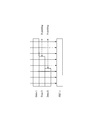
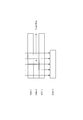
- a schematic diagram showing a packet sent from the sender to the receiver FIG. 2 is a schematic diagram showing that a data packet failed to be received is restored using the first row of the matrix shown in FIG. 2 by a conventional method.
- Block diagram showing a configuration example of a data transmission apparatus in the first embodiment of the present disclosure A schematic diagram for explaining the rearrangement process of data packets in the first embodiment of the present disclosure
- a schematic diagram showing the correspondence between the matrix and data packets for Step 2 of FIG. The schematic diagram which shows the specific example of the relationship between the data packet at the time of producing the redundant packet in 1st Embodiment of this indication, and a matrix
- the schematic diagram which shows an example of the format of the RTP header in 1st Embodiment of this indication The schematic diagram which shows an example of the format of the extension header of the RTP header in 1st Embodiment of this indication
- the schematic diagram which shows the specific example of the format of the FEC header in 1st Embodiment of this indication Block diagram showing a configuration example of a data receiving apparatus according to the first embodiment of the present disclosure
- the schematic diagram which shows the result of the 2nd simulation regarding the difference of the data reduction effect by the presence or absence of the rearrangement process of the data packet in 1st Embodiment of this indication A flowchart showing an example of main operation of the data transmission apparatus in the first embodiment of the present disclosure Flow chart showing an example of main operation by the data receiving apparatus in the first embodiment of the present disclosure Block diagram showing a configuration example of a data transmission apparatus according to the second embodiment of the present disclosure
- the schematic diagram which shows the 1st example of the format of the FEC header in 2nd Embodiment of this indication The schematic diagram which shows the 2nd example of the format of the FEC header in 2nd Embodiment of this indication
- Block diagram showing an example of configuration of a data receiving apparatus according to the second embodiment of the present disclosure A flowchart showing an example of main operation of the data transmission apparatus in the second embodiment of the present disclosure Block diagram showing a configuration example of a data transmission apparatus in the third embodiment of the present disclosure
- the schematic diagram which shows the specific example of the format of the FEC header in 3rd Embodiment of this indication Block diagram showing a configuration example of a data receiving apparatus according to the third embodiment of the present disclosure
- a flowchart showing an example of main operation of the data transmission apparatus in the third embodiment of the present disclosure A flowchart showing an example of main operation of the data receiving apparatus in the third embodiment of the present disclosure
- Block diagram showing a configuration example of a data transmission apparatus in the fourth embodiment of the present disclosure The schematic diagram which shows the specific example of the format of the FEC header in 4th Embodiment of this indication
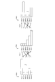
- FIG. 1 shows an example of an original data packet to be transmitted. There are six data packets: Data1, Data2, Data3, Data4, Data5, Data6. In FIG. 1, it is assumed that the data length of each packet is not constant. The original data packet is used to create a redundant packet.
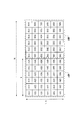
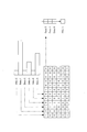
- FIG. 2 shows the matrix used to create redundant packets. Each element of the matrix is either "1" or "0". The rules for generating this matrix are described in Non-Patent Document 3.
- the redundant packet can be used to recover the original data packet by having the sender and the receiver have the same matrix or generate them.
- FIG. 3 is a diagram for explaining each element and configuration of this matrix.
- the matrices shown in FIG. 3 will be described separately for the groups A and B.
- the B group matrix (B11, B12,..., B65, B66) is a square matrix having the same number of rows and columns.
- the matrix of the group A (A11, A12,..., A65, A66) has the number of rows (N ⁇ k) and the number of columns k.
- the value of N depends on the number of redundant packets to be generated.
- FIG. 4 the redundant packet (FEC1) is created using the first row of the matrix shown in FIG.
- Each element Axy of the matrix of group A (x: variable representing row position, y: variable representing column position) is information used to identify an original data packet used to create a redundant packet.
- the matrix columns of group A correspond to the original data packets one to one.
- the data length of the FEC 1 is the same as that of the longest data Data 1 in FIG. In each data packet of Data1, Data3, and Data5, XOR (exclusive OR) of bits at the same position is performed. The calculation result is data of FEC1.
- Data1, Data3, and Data5 have mutually different data lengths.
- short data is zero-padded (0 padding), and the data is calculated after being aligned to the longest data length. That is, each bit at a position without data is regarded as "0" and XOR operation is performed.
- the data length of FEC2 is the same as the longest data packet among Data3, Data4, Data5, and FEC1. In the example of FIG. 5, since the data length of FEC1 is the longest, the data length of FEC2 is the same as FEC1.
- the matrix shown in FIG. 2 has six rows. By performing the same processing as the above-described processing (the processing in FIG. 4 and FIG. 5) for each row, six redundant packets (FEC1, FEC2, FEC3, FEC4, FEC5, FEC6) are created.
- FIG. 6 shows how a packet is transmitted from a communication apparatus on the transmission side (hereinafter referred to simply as the transmission side) to a communication apparatus on the reception side (hereinafter referred to simply as the transmission side).
- original data packets Data1, Data2, Data3, Data4, Data5, Data6
- redundant packets FEC1, FEC2, FEC3, FEC4, FEC5, FEC6
- the receiving side uses the redundant packet to recover the data packet that can not be received.
- the receiver checks if all the original data packets have been received. For acknowledgment of data packets, the receiver generates the same matrix as the sender.
- the first row of the matrix in FIG. 2 indicates that when redundant packets are created, XOR operation is performed using Data1, Data3, and Data5 to create FEC1. Therefore, conversely, the data of Data3 can be restored by XORing Data1, Data5, and FEC1.
- the transmitting side XOR's the data length values of Data1, Data3, and Data5 to calculate the value of “Length Recovery”, and adds it to the header of FEC1.
- the value of “Length Recovery” and the information of the data lengths of Data 1 and Data 5 are XOR-calculated to calculate the data length of Data 3.
- the packet length of the redundant packet to be created is determined by the length of the longest packet among the original plurality of data packets.
- the length of redundant packets eg, FEC packets
- the amount of data computation at the time of redundant packet generation and restoration may increase, or the communication load may increase.
- RTP Real-Time Transport Protocol
- FEC forward error correction
- the present disclosure can be similarly applied to data packets other than RTP data packets and redundant packets other than FEC packets.
- the communication apparatus of this embodiment includes a telephone, a transmitter and a receiver of a television signal, a transmitter and a receiver of a radio signal, a wired broadcast device, a mobile phone, a smartphone, a tablet, a personal computer, a camera with a communication function, a video with a communication function. It can be applied to various data communication devices such as cameras.
- the communication system of this embodiment will be described below with reference to FIGS. 8 to 21 and 38.
- data is communicated between the data transmitting apparatus 100 and the data receiving apparatus 150 via a predetermined communication path.
- the data transmission device 100 and the data reception device 150 are an example of a communication device.
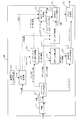
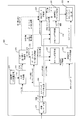
- FIG. 8 is a block diagram showing a configuration example of the data transmission apparatus 100 according to the first embodiment of the present disclosure.
- the data transmission apparatus 100 includes a video encoder unit 111, an RTP data packet creation unit 112, a communication path loss rate calculation unit 113, a matrix generation unit 114, a data packet rearrangement processing unit 115, and an RTP header correction unit.
- the transmission RTP packet generation unit 117, the FEC data generation unit 118, the FEC header generation unit 119, the transmission FEC packet generation unit 120, and the packet transmission unit 121 are provided.
- the video encoder unit 111 receives video input data such as a moving image or a still image from a video camera or the like, and performs encoding processing according to an algorithm defined by H.264 or the like.
- the video encoder unit 111 passes the video codec data after the encoding process to the RTP data packet creation unit 112.
- the RTP data packet creation unit 112 receives the video codec data from the video encoder unit 111 and creates an RTP data packet. For example, it is assumed that one picture data is encoded and divided into a plurality of data, and the result is made into a plurality of RTP data packets.
- FIG. 1 shows six data packets obtained by encoding according to H.264 and dividing data at slice boundaries.
- the RTP data packet creation unit 112 notifies the matrix generation unit 114 of the number of packets of the created data packet. This value corresponds to the value of k in the above description. Also, the RTP data packet creation unit 112 notifies the data packet reordering unit 115 of the number of packets “k” and the packet length of each data packet.
- the RTP data packet creation unit 112 creates an RTP header, and notifies the RTP header correction unit 116 and the FEC header creation unit 119 of information on the RTP header.
- the RTP header information is information of a header added to the RTP data packet.
- the RTP data packet creation unit 112 notifies the transmission RTP packet creation unit 117 of the RTP data packet. Note that instead of notifying the RTP data packet, pointer information indicating a place where the RTP data packet is held may be notified.
- the communication path loss rate calculation unit 113 calculates the packet loss rate (also simply referred to as loss) of the communication path. Specifically, loss rate information is received from the data receiving apparatus 150. Also, for example, based on the retransmission request from the data receiving apparatus 150, the communication path loss rate calculation unit 113 may calculate packet loss information by itself.
- the matrix generation unit 114 generates a matrix for generating a redundant packet based on the information on the number of packets from the RTP data packet generation unit 112 and the information on the loss rate from the channel loss rate calculation unit 113.
- a matrix generation algorithm in the matrix generation unit 114 a known method (for example, the method described in Non-Patent Document 2) can be adopted.
- the matrix generation unit 114 generates a matrix by the method described below.
- N k ⁇ k ⁇ k ⁇ k ⁇ k ⁇ k ⁇ k ⁇ k ⁇ k ⁇ k ⁇ k ⁇ k ⁇ k ⁇ k ⁇ k ⁇ k ⁇ k ⁇ k ⁇ k ⁇ k ⁇ k ⁇ k ⁇ k ⁇ k ⁇ k ⁇ k ⁇ k ⁇ k indicating the number of original data packets.
- the matrix generation unit 114 calculates the total number of packets N including the number of redundant packets and the number of data packets based on the loss rate from the communication path loss rate calculation unit 113.
- the loss rate is high, the recovery rate in the data receiving apparatus 150 can be increased by increasing the total number N of packets.
- the loss rate is low, the total number N of packets can be reduced.
- the number of redundant packets is denoted by “N ⁇ k”, and N ⁇ k. Further, the total number of packets N is determined by the data transmitting apparatus 100 and notified to the data receiving apparatus 150.
- the value of Seed may be fixed or dynamically changed.
- the matrix generation unit 114 may adjust the Seed so that, for example, the recovery rate is high.
- the value of the Seed is also notified to the data receiving apparatus 150 as the total number N of packets.
- the matrix generation unit 114 notifies the data packet reordering unit 115 and the FEC data creation unit 118 of the generated matrix data. Note that instead of notifying matrix data, pointer information indicating a position where matrix data is stored may be notified.
- the matrix generation unit 114 notifies the FEC header generation unit 119 of the matrix information.
- the matrix information includes values of the total number of packets N, the number of data packets k, and the Seed.
- the data packet reordering unit 115 receives information on matrix data from the matrix generation unit 114. Also, from the RTP data packet creation unit 112, information on the number k of data packets and the packet length of each packet is received.
- the data packet reordering unit 115 performs data packet reordering process for reordering RTP data packets based on the sum of packet lengths (packet sizes) of redundant packets. Specifically, the order of data packets is rearranged so that the sum of packet lengths (packet sizes) of redundant packets becomes a small value.
- the search method for data packet reordering may be a heuristic method. That is, even if the data packet reordering unit 115 calculates the data length of the redundant packet to be created for all cases, and finds out the order of arranging the data packets with the smallest total data length among them. Good. A specific example of data packet rearrangement will be described later.
- the data packet reordering unit 115 notifies the FEC data creation unit 118 and the RTP header correction unit 116 of data packet reordering information including the result of the data packet reordering process.
- the FEC data creation unit 118 creates a redundant packet (FEC packet) based on the matrix data, the RTP data packet, and the rearrangement information of the data packet. Also, in order to create redundant packets, there are cases in which redundant packets already created are used. In that case, the redundant packet is received from the transmission FEC packet creation unit 120, and a new redundant packet is created.
- FEC packet redundant packet
- the FEC data creation unit 118 also calculates the value of “Length recovery”.
- the calculation method of "Length recovery” is described, for example, in Non-Patent Document 1.
- “Length recovery” is information for recovering the packet length of the packet lost packet. That is, it is one of the packet length information for recovering the packet length of a loss or an improper packet which is not received normally.
- a non-normal packet refers to a packet lost during transmission and a packet in which a data error occurred during transmission.
- a packet in which a data error occurs during transmission is detected that an error has occurred on the receiving side, and if the error can not be corrected, the receiving side is treated equally as a packet lost during transmission.
- the FEC data creation unit 118 calculates “Length recovery” by performing an XOR operation process on the value of each packet length of a packet for creating a redundant packet.
- the FEC data creation unit 118 notifies the transmission FEC packet creation unit 120 of the data of the created redundant packet (redundant packet data), the value of “Length Recovery”, and information indicating what number the FEC packet is. These notifications may be pointer information indicating the destination of storage. The information indicating the number of the FEC packet corresponds to “FEC Sequence Number” in FIG.
- the RTP header correction unit 116 corrects the RTP header information by using the RTP header information generated by the RTP data packet generation unit 112 and the rearrangement information of the data packet generated by the data packet rearrangement processing unit 115. By using this corrected RTP header information, the data receiving apparatus 150 can recover the lost data packet.
- the transmission RTP packet creation unit 117 receives the RTP data packet from the RTP data packet creation unit 112, and receives the modified RTP header information (modified RTP header information) from the RTP header correction unit 116. In addition, the transmission RTP packet creation unit 117 creates an RTP data packet in which the modified RTP header information is added to the RTP data packet.
- the transmission RTP packet creation unit 117 passes the created RTP data packet to the FEC data creation unit 118 and the packet transmission unit 121. At this time, the RTP data packet itself may be passed, but a pointer indicating the position where the corresponding data is held may be passed. Since the process of reading and writing data on the memory takes time, it is more efficient to process by pointer operation.
- the FEC header creation unit 119 receives matrix information from the matrix generation unit 114, receives RTP header information from the RTP data packet creation unit 112, and generates a header (FEC header) of a redundant packet.
- the RTP header information includes a sequence number (see FIG. 13) for identifying the order of the RTP header.
- the FEC header creation unit 119 passes the created FEC header information to the transmission FEC packet creation unit 120. Note that instead of the FEC header information, pointer information of the FEC header information may be passed.
- the transmission FEC packet creation unit 120 receives redundant packet data, the value of “Length recovery”, and the value of “FEC Sequence Number” from the FEC data creation unit 118.
- the transmission FEC packet creation unit 120 also receives FEC header information from the FEC header creation unit 119.
- the transmission FEC packet creation unit 120 creates a redundant packet using data of the redundant packet, the value of “Length recovery”, the value of “FEC Sequence Number”, and the FEC header information. That is, the transmission FEC packet creation unit 120 creates a redundant packet (FEC packet) in which FEC header information is added to data of the redundant packet (FEC packet).
- the transmission FEC packet creation unit 120 passes the created redundant packet to the packet transmission unit 121. Although the redundant packet itself may be passed, instead, pointer information indicating the position where the redundant packet is held may be passed.
- redundant packets may be further generated using the redundant packets generated by the transmission FEC packet generation unit 120.
- the data of the redundant packet is passed from the transmission FEC packet generation unit 120 to the FEC data generation unit 118.
- pointer information may be passed which indicates the position where the data of the created redundant packet is stored.
- the packet sending unit 121 sends the RTP data packet created by the transmission RTP packet creating unit 117 and the redundant packet created by the transmission FEC packet creating unit 120 to the communication path.
- the data packet reordering unit 115 arranges data packets in order of shorter data length.
- the data packet reordering unit 115 performs reordering process in accordance with the elements of the matrix. It demonstrates using the value of element Axy of the matrix of A group shown in FIG.
- the data packet reordering unit 115 searches for the minimum value of x with respect to each value of y when the element Axy becomes “1”.
- the data packet reordering unit 115 arranges Axy so that the values x of the searched minimum values are in the ascending order, and allocates the data packets arranged in the ascending order in Step 1 to the corresponding columns.
- FIG. 9 shows an example of the case where the input data packet group PS10 has the same order of data packets (Data1 to Data6) as FIG.
- the data packet group PS10 is arranged in order of decreasing data length.
- the former ones are arranged in front (upper side in FIG. 9).
- the order of the data packet group PS11 output as a result of Step 1 is (Data2, Data4, Data6, Data5, Data3, Data1).
- Step 2 of FIG. 9 the process of Step 2 of FIG. 9 will be described in detail, assuming that the matrix configuration for forming redundant packets and each element of the matrix are the same as in FIGS. 2 and 3.
- the data packet reordering unit 115 searches for the minimum value of x with respect to the value of each y when the element Axy becomes “1”.
- A42, A13, A24, A15, and A36 are the smallest elements of the second, third, fourth, fifth, and sixth columns of the matrix.
- the data packet reordering unit 115 associates each element (A11, A13, A15, A24, A36, A42) with the data packet group PS11 arranged in the small order in Step 1.
- FIG. 10 is a diagram for explaining Step 2 of the data packet reordering process.
- the data packet group PS11 arranged in ascending order of data length is Data2, Data4, Data6, Data5, Data3, and Data1 in FIG. A row whose element is "1" is searched in order from the upper row of the matrix, and data with a short data length is allocated.
- FIG. 11 shows the correspondence between the matrix, the data packets assigned to each column of the matrix, and the redundant packet FEC1 created using the first row of the matrix.
- the arrangement order of data packets corresponding to each column of the matrix is It differs from the 4 example.
- the matrix of FIG. 11 is the same as the matrix shown in FIG.
- the first redundant packet (FEC1) is created.
- the data length of the redundant packet (FEC 1) can be shortened. If redundant packets are created without rearranging the data packets, as shown in FIG. 4, they are created from long Data1, Data3 and Data5 of the packet length, so the data length of the redundant packets also becomes long.
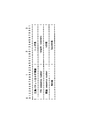
- FIG. 12 shows the comparison results of the data lengths of redundant packets when data packet reordering processing is performed and when data packet reordering is not performed.
- the same matrix as FIG. 2 is used about the matrix which produces a redundant packet.
- the data length of redundant packets (FEC1, FEC2, and FEC3) can be reduced by 87%, 75%, and 63%, respectively, by the rearrangement process of data packets. It can reduce 38%. As described above, by performing the data packet rearrangement process before creating the redundant packet, the data amount of the redundant packet can be effectively reduced.
- FIG. 15 is a view showing an example of the format of the FEC header.
- the header of the packet represents an area for holding various information necessary for the management of the packet, and is generally added to the head portion of the packet body to be integrated with the packet body and transmitted.
- the FEC header contains information indicating that the packet is a redundant packet. Also, header length information is included. Also, the value of “FEC sequence number” is included. The value of “FEC sequence number” is information indicating what number the redundant packet is. The value of “FEC sequence number” is determined by the FEC data creation unit 118, and is assigned to the header by the transmission FEC packet creation unit 120.
- the FEC header includes the value of “Length recovery”.
- the value of “Length recovery” is a value obtained by XORing the values of the packet length of the data packet and the redundant packet used when creating the redundant packet.
- the value of “Length recovery” is calculated by the FEC data creation unit 118 and assigned to the header by the transmission FEC packet creation unit 120.
- the FEC header includes the “start sequence number”, the value of k, the value of N, and the value of Seed. As these values, each information received by the FEC header creating unit 119 is assigned to the header.
- FIG. 13 is a view showing an example of the format of the RTP header. This format is defined in "IETF RFC 3550" RTP: A Transport Protocol for Real-Time Applications ".
- the data reception device 150 confirms “timestamp” and “sequence number”. Packets created from one picture are set to the same "timestamp” value. Moreover, the integer which increases to increment is set to "Sequence number”. Therefore, packet loss can be detected by checking "sequence number”.
- FIG. 14 is a diagram showing an example of a partial format of an extension header (RTP extension header: “header extension” in FIG. 13) of the RTP header.
- the extension header of the RTP header includes data packet reordering information as information indicating the reordering order of the data packets.
- the RTP header correction unit 116 sets the value of "2".
- the RTP header correction unit 116 sets a value of “1” in the area indicating the rearrangement information of the data packet of the extension header of the RTP header.
- the RTP header correction unit 116 notifies the transmission RTP packet generation unit 117 of the generated corrected RTP header information.
- the RTP data packet creation unit 112 receives video codec data from the video encoder unit 111 and creates an RTP data packet.
- the number of RTP data packets is k (step S101).
- the matrix generation unit 114 determines the total number N of packets including the number of redundant packets. (Step S102).
- the matrix generation unit 114 determines the value of Seed for matrix generation. For example, the value of Seed may be adjusted to increase the recovery rate.
- the matrix generation unit 114 generates a matrix based on the total number of packets N, the number of data packets k, and the Seed (step S103).
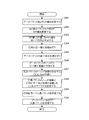
- the data packet reordering unit 115 performs data packet reordering processing (step S104).
- the RTP header correction unit 116 adds the rearrangement information of the data packet received from the data packet rearrangement processing unit 115 to the RTP header (step S105). This corrects the RTP header.
- the transmission RTP packet creation unit 117 creates an RTP data packet to be sent, using the corrected RTP header and the RTP data packet.
- the FEC header creation unit 119 creates FEC header information based on the matrix information from the matrix generation unit 114 and the RTP header information from the RTP data packet creation unit 112 (step S106).
- the FEC data generation unit 118 generates the matrix generated by the matrix generation unit 114, the RTP data packet generated by the transmission RTP packet generation unit 117, and the rearrangement information of the data packet generated by the data packet rearrangement processing unit 115. And create a redundant packet (step S107).
- the FEC data creation unit 118 calculates “Length recovery” based on the information of the packet length of the packet used to create the redundant packet. Also, the FEC data creation unit 118 passes the values of “FEC sequence number” and “Length recovery” included in the FEC header information to the transmission FEC packet creation unit 120.
- the transmission FEC packet creation unit 120 receives the FEC header information from the FEC header creation unit 119, the data of the redundant packet from the FEC data creation unit 118, the value of “Length recovery”, and “FEC sequence number”, Create redundant packets to be sent.
- steps S106 and S107 shown in FIG. 20 may be reversed.
- the packet transmission unit 121 receives the RTP data packet from the transmission RTP packet creation unit 117 and the redundant packet from the transmission FEC packet creation unit 120, and transmits it to the data receiving apparatus (step S108).
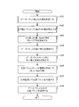
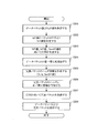
- FIG. 38 is a flowchart showing an example of the details of the data packet rearrangement process.
- the data packet reordering unit 115 arranges k data packets in order of decreasing packet length (step S11). For example, in the case of processing the six data packets shown in FIG. 1, as a result, they are arranged in the order of Data2, Data4, Data6, Data5, Data3, and Data1.
- the data packet reordering unit 115 extracts an element Axy in which the value of x is the smallest among elements of Axy of “1” at each y (step S12). ).
- the data packet reordering unit 115 reorders each element Axy extracted in step S12 in the order of small x (step S13). For example, as a result, they are arranged in the order of A11, A13, A15, A24, A36, and A42.
- the data packet reordering unit 115 associates each data packet of the result of step S11 with each element Axy of the result of step S13 in order (step S14). For example, the following results can be obtained. (Data2, A11), (Data4, A13), (Data6, A15), (Data5, A24), (Data3, A36), (Data1, A42)
- the data packet reordering unit 115 reorders the combinations associated in step S14 in the order based on y of each element Axy (step S15). For example, after reordering, the following results are obtained. (Data2, A11), (Data1, A42), (Data4, A13), (Data5, A24), (Data6, A15), (Data3, A36)
- the data packet reordering unit 115 extracts the data packet groups in order in accordance with the order of the combination of (Data, Axy) obtained as a result of step S15 (step S16).
- the order of the data packets to be taken out is as a result, in the order of Data2, Data1, Data4, Data5, Data6, Data3.
- the data packet reordering unit 115 determines that the packet length of the assigned data packet is the higher the row of the matrix data is. Reorder the data packets to be shorter.
- the data amount of redundant packets can be reduced. Therefore, the amount of data operation at the time of creating the redundant packet is reduced, and the processing load of the data transmission apparatus 100 can be reduced. Furthermore, since the amount of data sent to the communication path (transmission path) is also reduced, the bandwidth of the transmission path can be efficiently used. For example, even in the case of sharing the band of the transmission path by a plurality of users as in wireless communication, or even when the band of the transmission path is narrow, high speed communication with few errors can be implemented.
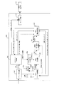
- FIG. 16 is a block diagram showing a configuration example of the data receiving device 150 in the first embodiment of the present disclosure.
- the data receiving apparatus 150 includes a packet receiving unit 151, an RTP packet holding unit 152, an FEC packet holding unit 153, an RTP packet loss determination unit 154, a loss rate calculation unit 155, a matrix generation unit 156, and FEC recovery.
- a processing unit 157, a video decoder unit 158, and a video display unit 159 are provided.
- the packet reception unit 151 receives a packet from the communication path, and distributes the received packet (received packet) to the RTP packet holding unit 152 or the FEC packet holding unit 153.
- the received packet includes at least one of RTP data packet and redundant packet.
- the packet reception unit 151 passes the received RTP data packet to the RTP packet holding unit 152, and passes the received redundant packet to the FEC packet holding unit 153.
- Data transfer of RTP data packets and redundant packets may be performed by pointer operation.
- the RTP packet holding unit 152 holds RTP data packet information.
- the RTP packet holding unit 152 receives RTP data packets from the packet reception unit 151. Also, the RTP packet holding unit 152 obtains video codec data from the RTP data packet, and passes it to the video decoder unit 158. Further, the RTP packet holding unit 152 passes the RTP data packet to the FEC recovery processing unit 157. For this transfer, pointer information storing data may be passed.
- the RTP packet holding unit 152 passes the rearrangement information of the data packet added to the RTP header to the FEC recovery processing unit 157. Further, the RTP packet holding unit 152 passes received packet information including the reception status, that is, information on whether or not there is a packet loss, to the RTP packet loss determination unit 154. Also, the RTP packet holding unit 152 receives the RTP data packet restored by the FEC restoration processing unit 157.
- the video decoder unit 158 receives the video codec data from the RTP packet holding unit 152, performs decoding processing and the like according to the rules such as H.264, and passes the resultant video data to the video display unit 159.
- the video display unit 159 displays the video from the video decoder unit 158.
- the RTP packet loss determination unit 154 receives the received packet information from the RTP packet holding unit 152, and determines whether or not a packet loss has occurred. If a packet loss has occurred, the matrix generation unit 156 is instructed to generate a matrix. Further, the RTP packet loss determination unit 154 notifies the loss rate calculation unit 155 of loss information including information as to whether or not a packet loss has occurred.
- the loss rate calculation unit 155 receives the loss information from the RTP packet loss determination unit 154, and receives the loss information from the FEC packet holding unit 153.
- the loss rate calculation unit 155 may calculate the loss rate based on the loss information and may notify the data transmission apparatus 100 of the loss rate.
- the FEC packet holding unit 153 holds information of redundant packets.
- the FEC packet holding unit 153 receives data of redundant packets from the packet receiving unit 151. Also, the FEC packet holding unit 153 notifies the FEC recovery processing unit 157 of data of redundant packets. With regard to this notification, pointer information storing data of redundant packets may be notified.
- the FEC packet holding unit 153 passes the matrix information for matrix generation added to the header to the matrix generation unit 156.
- the matrix information includes the total number of packets N, the number of RTP data packets k, and the value of Seed.
- the FEC packet holding unit 153 passes the loss information of the redundant packet to the loss rate calculation unit 155. Since the number of redundant packets can be estimated from the total number of packets N, it is possible to know the number of redundant packets not received, that is, the number of lost packets that failed to be received.
- the FEC packet holding unit 153 receives the redundant packet restored by the FEC restoration processing unit 157. By holding the restored redundant packet, it is possible to perform restoration processing recursively.
- the matrix generation unit 156 receives matrix information from the FEC packet holding unit 153, and generates a matrix based on the matrix information.
- the matrix generation unit 156 executes a process of generating a matrix when a matrix generation instruction is received from the RTP packet loss determination unit 154.
- the matrix generation unit 156 notifies the FEC recovery processing unit 157 of the matrix data.
- pointer information indicating a position where matrix data is stored may be notified.
- the matrix generation instruction may be generated so as to generate a packet each time it is received.
- the same matrix may be shared and held in advance with the data transmission apparatus 100 without using the matrix generation instruction.
- the FEC recovery processing unit 157 receives RTP data packets from the RTP packet holding unit 152, and receives data of redundant packets from the FEC packet holding unit 153. Also, it receives rearrangement information of data packets from the RTP packet holding unit 152, and receives matrix data from the matrix generation unit 156.
- the FEC recovery processing unit 157 rearranges the data packets based on the rearrangement information of the data packets. Also, the FEC recovery processing unit 157 recovers the lost packet based on the received information. The FEC recovery processing unit 157 passes the packet to the RTP packet holding unit 152 if the restored packet is an RTP data packet, and passes the packet to the FEC packet holding unit 153 if the packet is a redundant packet.
- the FEC recovery processing unit 157 identifies, from the reordering information of the data packet included in the extension header of the RTP header shown in FIG. Since the FEC recovery processing unit 157 may lose a plurality of packets, it determines whether recovery is possible based on the matrix data.
- FIG. 17 is a diagram showing a specific example of packet restoration processing.
- the data transmitting apparatus 100 creates a redundant packet after the rearrangement of the data packets shown in FIG. Further, it is assumed that the data receiving apparatus 150 sequentially receives Data4, Data5, FEC1, and FEC2 as the packet group PS21.
- the FEC recovery processing unit 157 grasps that Data 4 and Data 5 correspond to the third and fourth columns from the rearrangement information of the data packets included in the extension header of the RTP header shown in FIG. Similarly, the FEC recovery processing unit 157 also grasps that the data packet corresponding to the fifth column of the matrix is not received. The data packet corresponding to the fifth column of the matrix has not been recovered yet, and is therefore described as "Data?" In FIG.
- the FEC recovery processing unit 157 recognizes that the redundant packets FEC1 and FEC2 are received based on the FEC header of the redundant packet shown in FIG. Specifically, based on the values of “FEC sequence number”, “start sequence number”, and k, it is determined whether it is FEC1 or FEC2 of redundant packet.
- the FEC recovery processing unit 157 sets the packet length of the data packet corresponding to the fifth column of the matrix to the value of “Length recovery” included in the FEC header of FEC2 and the value of the packet length of Data4, Data5, FEC1. Calculate based on.
- the FEC recovery processing unit 157 restores the lost packet (Data?) By XORing Data4, Data5, FEC1, and FEC2 within the calculated packet length range. Do.
- the recovered packet is Data6.
- the restored RTP data packet is delivered to the RTP packet holding unit 152.
- the packet receiving unit 151 receives a packet.
- the RTP data packet is stored by the RTP packet storage unit 152, and the redundant packet is stored in the FEC packet storage unit 153.
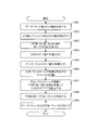
- the RTP packet loss determination unit 154 receives the received packet information from the RTP packet holding unit 152, and determines whether there is a packet loss (step S151). Whether or not there is a loss may be confirmed by the "Sequence Number" shown in FIG. When a loss is found, the RTP packet loss determination unit 154 transmits a matrix generation instruction to the matrix generation unit 156 to start restoration processing. That is, it progresses to the process after step S152.
- the FEC packet holding unit 153 passes the total number of packets N, the number of RTP data packets k, and the Seed value included in the matrix information to the matrix generation unit 156. Then, the matrix generation unit 156 generates a matrix (step S152).
- the FEC recovery processing unit 157 determines from the RTP header information whether or not the data packet rearrangement process is being performed (step S153). Whether or not the data packet reordering process is being performed can be determined by whether or not the data packet reordering information is added to the extension header of the RTP header. Although an example of data packet reordering information is shown in FIG. 14, it can be determined whether or not it is an extension header including data packet reordering information according to the value of “defined by profile”.
- the FEC recovery processing unit 157 performs the data packet rearrangement process (step S154). Then, the FEC recovery processing unit 157 performs recovery processing of the reordered packets (step S155).
- the FEC recovery processing unit 157 directly performs packet recovery processing (step S155).
- the FEC recovery processing unit 157 uses the recovered packet to check whether there is any more recoverable packet (step S156). If there is a packet that can be recovered, the FEC recovery processing unit 157 performs recovery processing (step S155).
- Recovery processing is performed on both data packets and redundant packets. This is because there are cases where packets can be recursively recovered by recovering the recovered packets.
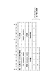
- Figures 18 (A), (B) and 19 (A), (B) show the results of how much reduction is achieved using actual data when video data is encoded and divided into packets. .
- FIGS. 18A and 18B show the results of processing 13 data packets (DATA1 to DATA13).
- FIG. 18A shows information on data of RTP data packet and redundant packet.
- FIG. 18B shows a matrix for generating redundant packet data.
- the reduction rate of data in the case of rearrangement is 88% for FEC1 and 74% for FEC2 as compared to the case where data packets are not rearranged.
- FEC3 is 4%.
- the total data volume of redundant packets is reduced by 13%.
- FIGS. 19A and 19B show results of processing 12 data packets (DATA1 to DATA12).
- FIG. 19A shows information on data of RTP data packet and redundant packet.
- FIG. 19B shows a matrix for generating redundant packet data.
- the reduction rate of data when sorting is performed is 76% for FEC1, 73% for FEC2, and when compared to the case where data sorting is not performed. 69% of FEC3, 10% of FEC4, and 1% of FEC5. In addition, the total data volume of redundant packets is reduced by 19%.
- the FEC recovery processing unit 157 is not normally received by the packet receiving unit 151 based on at least one of the rearranged data packet and the redundant packet and the matrix data. Restore the packet.
- a non-normal packet is a lost packet, and includes both a packet that has not been received and a packet that has been determined as an error by a CRC check or the like.
- the data packet can be reliably restored using at least one of the data packet and the redundant packet with a reduced amount of data.
- the data amount of redundant packets is reduced, the amount of data operation at the time of data packet restoration is reduced, and the processing load on the communication apparatus can be reduced.
- FIG. 22 is a block diagram showing a configuration example of a data transmission device 100B in the second embodiment of the present disclosure.
- components that perform substantially the same function as the data transmission apparatus 100 in the first embodiment are indicated by the same reference numerals.
- the data transmission apparatus 100B does not include the RTP header correction unit 116 and the transmission RTP packet creation unit 117 shown in FIG. Further, the function of the FEC header creating unit 119B is slightly different from the function of the FEC header creating unit 119 in FIG.
- the packet transmission unit 121 receives the RTP data packet from the RTP data packet creation unit 112. Further, the FEC data creation unit 118 receives the RTP data packet from the RTP data packet creation unit 112.
- the FEC header creating unit 119B receives matrix information from the matrix creating unit 114, receives RTP header information from the RTP data packet creating unit 112, and receives reordering information of data packets from the data packet reordering unit 115.
- the FEC header creation unit 119B creates an FEC header based on the received information.
- the FEC header creating unit 119B adds the rearrangement information of the data packet to the FEC header. Also, the FEC header creation unit 119B passes the created FEC header information to the packet transmission unit 121. This may be the transfer of pointer information.
- FIG. 23 is a diagram illustrating an example of a header (FEC header) of a redundant packet (FEC packet).
- FEC header a header of a redundant packet
- a different point from the FEC header of the first embodiment is that data packet reordering information is included as additional information in the area following the Seed value.
- the “FEC sequence number” is not the FEC header creating unit 119 B, but the FEC data creating unit 118 determines the value, and the transmission FEC packet creating unit 120 adds the value to the FEC header.
- the FEC header creating unit 119 may receive the information of “FEC Sequence number” from the FEC data creating unit 118, and the FEC header creating unit 119 may add the information to the FEC header.
- the FEC data creating unit 118 calculates a value, and the transmission FEC packet creating unit 120 adds the value to the FEC header.
- the FEC header creating unit 119 may receive the information of “Length recovery” from the FEC data creating unit 118, and the FEC header creating unit 119 may add the information to the FEC header.
- the value received by the FEC header creation unit 119B is set in the header.
- the transmission FEC packet creation unit 120 can be implemented to set the “start sequence number”.
- RTP header information may not be delivered from the RTP data packet creation unit 112 to the FEC header creation unit 119B.
- an area for retaining data packet reordering information is allocated.
- six numbers “2”, “1”, “4”, “5”, “6”, and “3” are written as data packet rearrangement information.
- FIG. 23 shows the contents to be written in the header as a result of the rearrangement of the data packets shown in FIG. That is, the rearrangement information of the data packets in FIG. 23 indicates that the data packets after the rearrangement in FIG. 9 are arranged in the order of Data2, Data1, Data4, Data5, Data6, Data3.
- the “start sequence number” included in the FEC header shown in FIG. 23 is the “Sequence Number” of the first RTP data packet Data1.
- the “Sequence Number” of the RTP data packet other than Data 1 can be easily calculated by the FEC header creation unit 119B based on the “start sequence number” and the data packet reordering information.
- the format shown in FIG. 24 may be used.
- the RTP data packet creation unit 112 receives video codec data from the video encoder unit 111 and creates an RTP data packet.
- the number of RTP data packets is k (step S201).
- the matrix generation unit 114 determines the total number N of packets including the number of redundant packets. Are determined (step S202).
- the matrix generation unit 114 determines the value of Seed for matrix generation.
- the matrix generation unit 114 generates a matrix based on the total number of packets N, the number of RTP data packets k, and the Seed (step S203).
- the data packet reordering unit 115 performs data packet reordering processing (step S204).
- the data packet reordering unit 115 reorders the RTP data packets so that the sum of the data lengths of the redundant packets becomes a small value.
- the FEC header creation unit 119B creates FEC header information based on the matrix information from the matrix generation unit 114 and the RTP header information from the RTP data packet creation unit 112 (step S205).
- the FEC header creation unit 119B adds the rearrangement information of the data packet received from the data packet rearrangement processing unit 115 to the FEC header (step S206).
- the FEC data generation unit 118 generates the matrix generated by the matrix generation unit 114, the RTP data packet generated by the RTP data packet generation unit 112, and the rearrangement information of the data packet generated by the data packet rearrangement processing unit 115. And create a redundant packet (step S207).
- the FEC data creation unit 118 calculates “Length recovery” based on the information of the packet length of the packet used when creating the redundant packet. Also, the FEC data creation unit 118 passes the values of “FEC sequence number” and “Length recovery” included in the FEC header information to the transmission FEC packet creation unit 120.
- the transmission FEC packet creation unit 120 receives the FEC header information from the FEC header creation unit 119B, the data of the redundant packet from the FEC data creation unit 118, and “Length recovery” and “FEC sequence number”. The transmission FEC packet creation unit 120 creates a redundant packet to be sent, using the received information.
- the packet transmission unit 121 receives the RTP data packet from the RTP data packet creation unit 112, and receives the redundant packet from the transmission FEC packet creation unit 120.
- the packet sending unit 121 sends the RTP data packet and the redundant packet toward the data receiving apparatus 150B (step S208).
- FIG. 25 is a block diagram showing a configuration example of a data reception device 150B in the second embodiment of the present disclosure.
- components that perform substantially the same function as the data reception device 150 in the first embodiment are indicated by the same reference numerals.
- the configuration of the data receiving apparatus 150B is substantially the same as that of the data receiving apparatus 150 of FIG.
- the function of the RTP packet holding unit 152B and the function of the FEC packet holding unit 153B in FIG. 25 are slightly changed.
- the RTP packet holding unit 152B holds information of RTP data packets.
- the RTP data packet is received from the packet reception unit 151.
- the RTP packet holding unit 152 B obtains video codec data from the RTP data packet, and passes it to the video decoder unit 158.
- the RTP packet holding unit 152 B passes the RTP data packet to the FEC recovery processing unit 157.
- the delivery may be pointer information indicating a position at which data is stored.
- the RTP packet holding unit 152 B passes the reception packet information including the reception status, that is, the information as to whether or not there is a packet loss, to the RTP packet loss judgment unit 154. Also, the RTP packet holding unit 152 B receives the RTP data packet restored by the FEC restoration processing unit 157.
- the FEC packet holding unit 153B holds redundant packet information.
- the FEC packet holding unit 153 B receives data of redundant packets from the packet receiving unit 151. Further, the FEC packet holding unit 153B notifies the FEC recovery processing unit 157 of the data of the redundant packet. This notification may be pointer information indicating a position at which data is stored.
- the FEC packet holding unit 153B passes the matrix information added to the FEC header to the matrix generation unit 156. Further, the FEC packet holding unit 153 B passes the loss information of the redundant packet to the loss rate calculation unit 155.
- the number of redundant packets to be received can be known from the total number of packets N and the number of data packets k, so the number of redundant packets not received can be grasped.
- the FEC packet holding unit 153 B receives the redundant packet restored by the FEC restoration processing unit 157. By holding the restored redundant packet, it is possible to perform restoration processing recursively.
- the FEC packet holding unit 153B passes the rearrangement information of the data packet added to the FEC header to the FEC recovery processing unit 157.
- the FEC recovery processing unit 157 receives an RTP data packet from the RTP packet holding unit 152B, and receives data of a redundant packet from the FEC packet holding unit 153B. Also, it receives rearrangement information of data packets from the FEC recovery processing unit 157 and receives matrix data from the matrix generation unit 114.
- the FEC recovery processing unit 157 recovers the lost packet based on the received information.
- the FEC recovery processing unit 157 delivers the recovered packet to the RTP packet holding unit 152B if the recovered packet is an RTP data packet, and passes it to the FEC packet storage unit 153B if the recovered packet is a redundant packet.
- the flow of the process in the data receiving apparatus 150B is the same as the flow of the process (FIG. 21) in the data receiving apparatus 150 of the first embodiment, so the description will be omitted.
- FIG. 27 is a block diagram illustrating a configuration example of the data transmission device 200 in the third embodiment of the present disclosure.
- the data transmission apparatus 200 includes a video encoder unit 211, an RTP data packet creation unit 212, a channel loss rate calculation unit 213, a matrix generation unit 214, a matrix rearrangement processing unit 215, and data packet rearrangement processing. And an RTP header correction unit 217, a transmission RTP packet generation unit 218, an FEC data generation unit 219, an FEC header generation unit 220, a transmission FEC packet generation unit 221, and a packet transmission unit 222.
- the video encoder unit 211 is the same as the video encoder unit 111 of FIG.
- the RTP data packet creation unit 212 is the same as the RTP data packet creation unit 112 of FIG.
- the communication path loss rate calculation unit 213 is the same as the communication path loss rate calculation unit 113 of FIG.
- the FEC data creation unit 219 is the same as the FEC header creation unit 119 of FIG.
- the FEC data creation unit 219 is the same as the FEC data creation unit 118 of FIG.
- the RTP header correction unit 217 is the same as the RTP header correction unit 116 in FIG.
- the transmission RTP packet creation unit 218 is the same as the transmission RTP packet creation unit 117 of FIG.
- the transmission FEC packet creation unit 221 is the same as the transmission FEC packet creation unit 120 in FIG.
- the packet sending unit 222 is the same as the packet sending unit 121 of FIG.
- the matrix generation unit 214 generates a matrix for generating a redundant packet based on the value of the packet number k from the RTP data packet generation unit 212 and the loss rate information from the communication path loss rate calculation unit 213.
- the matrix generation method is the same as the matrix generation method by the matrix generation unit 114.
- the matrix generation unit 214 notifies the generated matrix data to the matrix rearrangement processing unit 215.
- pointer information indicating a position where matrix data is stored may be notified.
- the matrix reordering unit 215 receives matrix data from the matrix generation unit 214.
- the matrix reordering unit 215 performs matrix reordering processing on the matrix data in which the rows are reordered, and notifies the FEC data creation unit 219 of the reordered matrix data.
- the matrix reordering unit 215 notifies the FEC header creating unit 220 of matrix reordering information obtained by the matrix information and matrix reordering process. Further, the matrix reordering unit 215 notifies the data packet reordering unit 216 of the reordered matrix data. Notification of matrix data may be notification of pointer information indicating a position where matrix data is stored.
- the matrix generation unit 214 and the matrix rearrangement processing unit 215 are provided as independent components, these processing units may be integrated.
- the data packet reordering unit 216 receives the reordered matrix data from the matrix reordering unit 215, and receives from the RTP data packet creation unit 212 information on the number k of data packets and the packet length of each data packet.
- the data packet reordering unit 216 reorders the data packets based on the reordered matrix data.
- the data packet reordering method is the same as the data packet reordering method by the data packet reordering unit 115.
- the matrix reordering process is performed before the data packet reordering process. It is not excluded that the data packet reordering process is performed before the matrix reordering process.
- the data packet reordering unit 216 notifies the FEC data creation unit 219 and the RTP header correction unit 217 of data packet reordering information as a result of the data packet reordering process.
- the FEC data creation unit 219 creates redundant packets based on the reordered matrix data, RTP data packets, and data packet reordering information. Also, in order to create redundant packets, there are cases in which redundant packets already created are used. In that case, the redundant packet is received from the transmission FEC packet creation unit 221, and a new redundant packet is created.
- the FEC data creation unit 219 also calculates the value of “Length recovery”.
- the FEC data creation unit 219 notifies the transmission FEC packet creation unit 221 of the FEC header information including the created data of the redundant packet, the value of “Length Recovery”, and “FEC Sequence Number”. This notification may be pointer information indicating a saved destination.
- the FEC header creating unit 220 receives matrix information and matrix reordering information from the matrix reordering unit 215, and receives RTP header information from the RTP data packet creating unit 212.
- the FEC header creation unit 220 creates an FEC header based on the received information.
- FIG. 29 is a diagram showing a specific example of the FEC header of the redundant packet.
- a flag F1 (a bit written as “M”) indicating whether or not to perform matrix rearrangement is prepared in MSB (most significant bit: most significant bit) It is that you are.
- MSB most significant bit: most significant bit
- FIG. 29 is an example, and does not limit where in the FEC header the information indicating that the matrix rearrangement process has been performed is placed.
- the information indicating that the matrix rearrangement process has been performed is not limited to being represented by one bit.
- the position to which the information indicating that the matrix rearrangement process has been performed is added is not limited to the FEC header.
- the matrix reordering unit is configured to move rows that can reduce the packet length of redundant packets upward by using the ability to reduce the packet length of redundant packets as the rows above the matrix 215 performs line sorting processing.
- the matrix reordering unit 215 moves the row with a small number of "1" to the top of the matrix.
- the matrix reordering unit 215 considers that the column in which the element of the upper row is “1” is already assigned the corresponding data packet, and only the column to which the data packet is not yet assigned. Take out. Then, the matrix reordering unit 215 selects a row in which the number of “1” s is small for the element. The matrix reordering unit 215 moves the selected row to the top of the row not yet moved in the matrix.
- the matrix reordering unit 215 performs a matrix reordering process on each element (Axy) of the matrix of group A. None is done about each element (Bxy) of the matrix of B group.
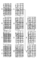
- FIG. 28 shows the state change of the matrix due to the matrix rearrangement process.
- the first state "M0" in FIG. 28 is the same as the matrix in FIG. 19 (B).
- the number of “1” s included in each row of the matrix is shown on the right side of each row.
- the row numbers prior to the matrix reordering process at each timing are shown on the left side of the matrix. Since the row in which the number of “1” s is the smallest is the ninth row (L9), L9 is moved to the top of the matrix.
- the state after movement is indicated as "M1".
- the method of rearranging the rows of the matrix described above is an example, and another method may be used.
- the same processing may be performed on the data transmission device 200 side and the data reception device 250 side.
- the RTP data packet creation unit 212 receives video codec data from the video encoder unit 211 and creates an RTP data packet.
- the number of RTP data packets is determined as the value of k (step S301).
- the matrix generation unit 214 calculates the total number N of packets including the number of redundant packets. It determines (step S302).
- the matrix generation unit 214 determines the value of Seed for matrix generation.
- the matrix generation unit 214 generates a matrix based on the total number of packets N, the number of data packets k, and the value of Seed (step S303).
- the matrix reordering unit 215 performs matrix reordering processing (step S304).
- the data packet reordering unit 216 reorders the data packets (step S305).
- the RTP header correction unit 217 adds the rearrangement information of the data packet to the extension header of the RTP header based on the rearrangement information of the data packet received from the data packet rearrangement processing unit 216 (step S306).
- the format of the RTP header for adding data packet reordering information may be the same as the example shown in FIG.
- the transmission RTP packet creation unit 218 generates an RTP data packet to be transmitted, using the modified RTP header and the RTP data packet.
- the FEC header creating unit 220 creates FEC header information based on the matrix information and the matrix reordering information from the matrix reordering unit 215 and the RTP header information from the RTP data packet creating unit 212. (Step S307).
- the FEC header creating unit 220 sets information indicating that the matrix rearrangement process has been performed to the FEC header information (step S308). Specifically, a flag F1 of "M" bit in the header format of FIG. 29 is set.
- the FEC data creation unit 219 creates redundant packets (step S309).
- the FEC data creation unit 219 calculates “Length recovery” based on the information of the packet length of the packet used when creating the redundant packet.
- the FEC data creation unit 219 passes the values of “FEC sequence number” and “Length recovery” included in the FEC header information to the transmission FEC packet creation unit 221.
- the transmission FEC packet creation unit 221 receives the FEC header information from the FEC header creation unit 220. In addition, the transmission FEC packet creation unit 221 receives, from the FEC data creation unit 219, data of redundant packets, values of “Length recovery”, and “FEC sequence number”. The transmission FEC packet creation unit 221 creates a redundant packet to be sent, using the received information.
- the packet sending unit 222 receives the RTP data packet from the transmission RTP packet creating unit 218, and receives the redundant packet from the transmission FEC packet creating unit 221.
- the packet sending unit 222 transmits the RTP data packet and the FEC packet to the data receiving apparatus 250 (step S310).
- FIG. 39 is a diagram showing the procedure of the matrix reordering process in the matrix reordering unit 215. As shown in FIG. That is, FIG. 39 shows details of the process of step S304 of FIG.
- the matrix reordering unit 215 initializes variables used during the matrix reordering process. Specifically, the variable of "number of lines of movement completion" is initialized to 0, and the variable of “number of lines of unimplemented movement” is initialized to the state of "NK" (step S21).
- the matrix reordering unit 215 checks the elements of each row of the movement completion row of the matrix, and extracts columns all of which are “0”. Further, the matrix reordering unit 215 calculates, for each of the extracted columns, the number of columns for which the element is “1” in each row for which movement has not been performed (step S22).
- the matrix reordering unit 215 identifies whether or not the calculated number of “1” s has become 0 in all the rows for which movement has not been performed (step S23).
- the matrix reordering unit 215 extracts the row for which the calculated number of “1” is the smallest among the unmoving rows of the matrix. If there are multiple rows with the smallest number of “1” s, extract the row above.
- the matrix reordering unit 215 moves the extracted row to the bottom of the row of movement completion.
- the matrix reordering unit 215 adds one to the value of “number of rows of movement completion” and subtracts one from the value of “number of rows not yet subjected to movement” (step S26).
- the matrix reordering unit 215 refers to the variable “number of rows yet to be moved” and determines whether the number of rows not yet moved is 0 (step S 27). If the "number of lines not yet moved” is not 0, the process returns to step S22, and if the "number of lines not yet moved” is 0, the process is ended.
- the matrix reordering unit 215 assigns a data packet to each column of matrix data
- the number of packets of the data packet to be assigned decreases in the higher row of the matrix data. So, sort the rows of matrix data.
- the data amount of the redundant packet to be generated can be further reduced by rearranging the rows of the matrix in a desired order.
- FIG. 30 is a block diagram showing a configuration example of the data receiving device 250 in the third embodiment of the present disclosure.
- the data receiving apparatus 250 includes a packet receiving unit 251, an RTP packet holding unit 252, an FEC packet holding unit 253, an RTP packet loss determination unit 254, a loss rate calculating unit 255, a matrix generation unit 256, and matrix arrangement.
- a replacement processing unit 257, an FEC recovery processing unit 258, a video decoder unit 259, and a video display unit 260 are provided.
- the packet receiving unit 251 is the same as the packet receiving unit 151 of FIG.
- the RTP packet holding unit 252 is the same as the RTP packet holding unit 152 in FIG.
- the RTP packet loss determination unit 254 is the same as the RTP packet loss determination unit 154 of FIG.
- the loss rate calculation unit 255 is the same as the loss rate calculation unit 155 of FIG.
- the video decoder unit 259 is the same as the video decoder unit 158 of FIG.
- the FEC packet holding unit 253 receives data of redundant packets from the packet receiving unit 251. Further, the FEC packet holding unit 253 notifies the FEC recovery processing unit 258 of the data of the redundant packet. This notification may be pointer information indicating a position where data is stored.
- the FEC packet holding unit 253 passes the matrix information included in the FEC header to the matrix generation unit 256. Further, the FEC packet holding unit 253 passes the loss information of the redundant packet to the loss rate calculation unit 255. Since the number of redundant packets is known from the total number of packets N, the number of redundant packets not received can be grasped.
- the FEC packet holding unit 253 receives the redundant packet restored by the FEC restoration processing unit 258. By holding the restored redundant packet, it is possible to make the FEC restoration process recursively possible.
- the FEC packet holding unit 253 notifies the matrix reordering unit 257 of matrix reordering information.
- the matrix generation unit 256 and the matrix rearrangement processing unit 257 may be integrated into one processing unit.
- the matrix information passed to the matrix generation unit 256 may include matrix rearrangement information.
- 1-bit information (flag F1) indicating whether or not to perform matrix rearrangement processing is used.
- the result of the matrix rearrangement process may be stored in the FEC header instead of the 1-bit information. That is, it may be numerical sequence information indicating the order of the lines after the line rearrangement.
- the process information which shows line rearranging procedure may be sufficient.
- the line rearrangement procedure information itself may not be index information indicating what kind of procedure it is.
- the matrix generation unit 256 receives matrix information from the FEC packet holding unit 253, and generates a matrix based on the matrix information.
- the matrix generation unit 256 executes a process of generating a matrix when a matrix generation instruction is received from the RTP packet loss determination unit 254.
- the matrix generation unit 256 notifies the matrix reordering unit 257 of the generated matrix data.
- the notification may be pointer information indicating a position where matrix data is stored.
- the matrix reordering unit 257 receives matrix data from the matrix generation unit 256, and receives matrix reordering information from the FEC packet holding unit 253.
- the matrix rearrangement processing unit 257 indicates that performing the matrix rearrangement processing is indicated in the FEC header, that is, when the flag F1 is included in the FEC header, the matrix rearrangement processing that rearranges the rows of the matrix is performed. Conduct.
- the matrix reordering unit 257 passes the reordered matrix data to the FEC recovery processing unit 258. This passing may be pointer information indicating a position where matrix data is stored.
- the algorithm of the matrix reordering process performed by the matrix reordering unit 257 may be the same as the process (content in FIG. 39) performed by the matrix reordering unit 215 of the data transmission device 200.
- the FEC recovery processing unit 258 receives RTP data packets from the RTP packet holding unit 252, and receives data of redundant packets from the FEC packet holding unit 253. Further, the FEC recovery processing unit 258 receives rearrangement information of data packets from the RTP packet holding unit 252, and receives the rearranged matrix data from the matrix rearrangement processing unit 257.
- the FEC recovery processing unit 258 rearranges the data packets based on the rearrangement information of the data packets. Also, the FEC recovery processing unit 258 recovers the lost packet based on the received information. If the restored packet is an RTP data packet, the FEC recovery processing unit 258 passes the packet to the RTP packet holding unit 252, and if it is a redundant packet, transfers the packet to the FEC packet holding unit 253.
- the FEC recovery processing by the FEC recovery processing unit 258 may be the same as the FEC recovery processing by the FEC recovery processing unit 157.
- the matrix reordering process is performed.
- the FEC recovery processing unit 258 may receive the rearranged matrix data from the matrix generation unit 256.
- the packet reception unit 251 receives a packet, and the RTP packet holding unit 252 stores the RTP data packet.
- the RTP packet loss determination unit 254 receives the received packet information from the RTP packet holding unit 252, and determines whether there is a packet loss of an RTP data packet based on the received packet information (step S351). When a loss is found, the RTP packet loss determination unit 254 transmits a matrix generation instruction to the matrix generation unit 256, and restoration processing is started. That is, it progresses to the process after step S352.
- the values of the total packet number N, the data packet number k, and the Seed included in the matrix information are passed from the FEC packet holding unit 253 to the matrix generation unit 256. Then, the matrix generation unit 214 generates a matrix (step S352).
- the FEC packet holding unit 253 identifies whether or not the matrix rearrangement process is to be performed from the information (for example, the flag F1 in FIG. 29) included in the FEC header (step S353).
- the matrix reordering unit 257 performs the process (step S354).
- the matrix rearrangement process is not performed, the matrix is left as it is.
- the FEC recovery processing unit 258 determines from the RTP header information whether or not the data packet has been rearranged (step S355).
- the FEC recovery processing unit 258 performs the data packet reordering process (step S356). Then, the FEC recovery processing unit 258 performs recovery processing of the rearranged data packet (step S357).
- the FEC recovery processing unit 258 performs the packet recovery processing as it is (step S357).
- the FEC recovery processing unit 258 checks whether there is a packet that can be further recovered using the recovered packet (step S 358), and the FEC recovery processing unit 258 performs recovery processing if there is a packet that can be recovered. (Step S357).
- Packets to be subjected to restoration processing are both data packets and redundant packets. This is because by recovering redundant packets, there may be packets that can be recovered recursively.
- FIG. 31 shows the result of how much the reduction effect is obtained using the actual data when the video data is encoded and divided into packets.
- the example of FIG. 31 shows the result of processing 12 data packets (DATA1 to DATA12: the same as the data shown in FIG. 19).
- the contents of the matrix rearrangement process in this simulation and the matrix after the rearrangement are the same as the matrix shown in FIG.
- FIG. 31 shows the result D31A of the data packet rearrangement process and the result D31B of the data packet rearrangement process and the matrix rearrangement process distinguished from each other.
- the result D31A in FIG. 31 indicates the data reduction rate when the data packet rearrangement process is performed. In other words, it shows the reduction effect.
- the data packet reordering process is performed after the matrix reordering process is performed on the data reduction rate when neither the data packet reordering process nor the matrix reordering process is performed. Shows the reduction rate of data when In other words, it shows the reduction effect.
- FEC 1 85%
- FEC 2 73%
- FEC 3 73%
- FEC 4 10%
- FEC 5 1%. Also, comparing the total data volume of redundant packets, it can be seen that there is a 26% reduction effect.
- the data amount of redundant packets can be reduced. Furthermore, as in the third embodiment, if redundant packets are created after performing matrix rearrangement processing and data packet rearrangement processing, the data amount of redundant packets can be further reduced.
- the FEC recovery processing unit 258 recovers the non-normal packet based on at least one of the post-reordering data packet and the redundant packet and the post-reordering matrix data.
- data packets and matrices can be rearranged in the same order as the desired order rearranged on the data transmitting apparatus 200 side. Therefore, the amount of data at the time of restoration of the lost packet can be further reduced.
- FIG. 34 is a block diagram showing a configuration example of a data transmission device 200B in the fourth embodiment of the present disclosure.
- components that perform substantially the same function as the data transmission apparatus 200 in the third embodiment are indicated by the same reference numerals.
- the data transmission device 200B does not include the RTP header correction unit 217 and the transmission RTP packet creation unit 218 shown in FIG. Also, the function of the FEC header creating unit 220B is slightly different from the function of the FEC header creating unit 220 shown in FIG.
- the packet sending unit 222 receives the RTP data packet from the RTP data packet creating unit 212. Further, the FEC data creation unit 219 receives the RTP data packet from the RTP data packet creation unit 212.
- the FEC header creating unit 220B receives the matrix information and the matrix sorting information from the matrix sorting processing unit 215, and receives the RTP header information from the RTP data packet creating unit 212. Further, the FEC header creation unit 220 B receives the data packet rearrangement information from the data packet rearrangement processing unit 216. The FEC header creation unit 220B creates an FEC header based on the received information.
- the FEC header creation unit 220B passes the created FEC header information to the transmission FEC packet creation unit 221. This transfer may be transfer of pointer information indicating a position where the FEC header information exists.
- FIG. 35 shows an example of the FEC header.
- the FEC header shown in FIG. 35 includes an area for storing a flag F1 indicating presence or absence of matrix rearrangement. Also, the FEC header shown in FIG. 35 includes an area for storing data packet rearrangement information. The rearrangement information of the data packet stored in the FEC header shown in FIG. 35 is the same as the rearrangement information of the data packet stored in the FEC header described in the second embodiment.
- the RTP data packet creation unit 212 receives video codec data from the video encoder unit 211 and creates an RTP data packet.
- the number of RTP data packets is determined as the value of k (step S401).
- the matrix generation unit 214 calculates the total number N of packets including the number of redundant packets. It determines (step S402).
- the matrix generation unit 214 determines the value of Seed for matrix generation. Then, the matrix generation unit 214 generates a matrix based on the value of the total number of packets N, the number of data packets k, and the value of Seed (step S403).
- the matrix reordering unit 215 performs matrix reordering processing (step S404).
- the data packet reordering unit 216 reorders the data packets (step S405).
- the FEC header creation unit 220B creates FEC header information (step S406).
- the FEC header creation unit 220B sets, in the FEC header information, information indicating that the matrix rearrangement process has been performed (step S407). Specifically, flag F1 (M bit) of the header format shown in FIG. 35 is set.
- the FEC data creation unit 219 creates redundant packets (step S408).
- the FEC data creation unit 219 calculates “Length recovery” using the packet length information of the packet used when creating the redundant packet. Also, the FEC data creation unit 219 passes the values of “FEC sequence number” and “Length recovery” included in the FEC header information to the transmission FEC packet creation unit 221.
- the transmission FEC packet creation unit 221 receives the FEC header information from the FEC header creation unit 220B, the redundant packet data from the FEC data creation unit 219, the value of “Length recovery”, and the “FEC sequence number”. The transmission FEC packet creation unit 221 creates a redundant packet to be sent based on the received information.
- the packet sending unit 222 receives the RTP data packet from the RTP data packet creating unit 212, and receives the redundant packet from the transmission FEC packet creating unit 221.
- the packet sending unit 222 sends the RTP data packet and the redundant packet toward the data receiving apparatus 250B (step S409).
- FIG. 36 is a block diagram showing a configuration example of a data reception device 250B in the fourth embodiment of the present disclosure.
- components that perform substantially the same function as the data reception device 150 in the first embodiment are indicated by the same reference numerals.
- the configuration of the data receiving apparatus 250B is substantially the same as that of the data receiving apparatus 250 of FIG.
- the function of the RTP packet holding unit 252B and the function of the FEC packet holding unit 253B are slightly changed.
- the RTP packet holding unit 252 B receives an RTP data packet from the packet reception unit 251.
- the RTP packet holding unit 252 B obtains video codec data from the RTP data packet, and passes it to the video decoder unit 259.
- the RTP packet holding unit 252 B passes the RTP data packet to the FEC recovery processing unit 258.
- This transfer may be pointer information indicating the position where the RTP data packet is stored.
- the RTP packet holding unit 252B passes the reception packet information including the reception status, that is, information as to whether or not there is a packet loss to the RTP packet loss determination unit 254. Further, the RTP packet holding unit 252 B receives the RTP data packet restored from the FEC restoration processing unit 258.
- the FEC packet holding unit 253 B receives data of redundant packets from the packet receiving unit 251. Further, the FEC packet holding unit 253B notifies the data of the redundant packet to the FEC recovery processing unit 258. This notification may be pointer information indicating a position where data is stored.
- the FEC packet holding unit 253B passes the matrix information added to the FEC header to the matrix generation unit 256. Also, the FEC packet holding unit 253B passes the loss information of the redundant packet to the loss rate calculation unit 255.
- the number of redundant packets to be received can be known from the total number of packets N and the number of data packets k, so the number of redundant packets not received can be grasped.
- the FEC packet holding unit 253 B receives the redundant packet restored by the FEC restoration processing unit 258. By holding the restored redundant packet, it is possible to make the FEC restoration process recursively possible.
- the FEC packet holding unit 253B passes the rearrangement information of the data packet added to the FEC header to the FEC recovery processing unit 258. Also, the FEC packet holding unit 253B notifies the matrix reordering unit 257 of matrix reordering information.
- the present disclosure is not limited to the configuration of the above-described embodiment, but may be any configuration that can achieve the function indicated by the claims or the function of the configuration of the present embodiment. Is also applicable.
- the present disclosure is described using hardware as an example, but the present disclosure can also be realized by software in cooperation with hardware.
- each functional block used in the description of the above-described embodiment is typically implemented as an LSI which is an integrated circuit. These may be individually made into one chip, or may be made into one chip so as to include some or all. Although an LSI is used here, it may be called an IC, a system LSI, a super LSI, or an ultra LSI depending on the degree of integration.
- circuit integration is not limited to LSI's, and implementation using dedicated circuitry or general purpose processors is also possible.
- a field programmable gate array FPGA
- FPGA field programmable gate array
- connection of circuit cells inside the LSI or a reconfigurable processor that can reconfigure settings can be used.
- the first communication device of the present disclosure is A data packet generator for generating data packets; A data reordering unit for reordering the data packets; A redundant packet generation unit that generates a redundant packet for the data packet based on the data packet rearranged by the data rearrangement processing unit and matrix data applied to the data packet; Equipped with
- the second communication device of the present disclosure is the first communication device, and A matrix data generation unit that generates the matrix data is provided.
- the third communication device of the present disclosure is the first or second communication device, and
- the data reordering unit reorders the data packets based on the sum of packet sizes of the redundant packets.
- the fourth communication device of the present disclosure is the third communication device, and
- the data reordering unit reorders the data packets such that the sum of packet sizes of the redundant packets is reduced.
- a fifth communication device of the present disclosure is any one of the first to fourth communication devices,
- the data rearrangement processing unit rearranges the data packet so that the packet length of the data packet to be allocated becomes shorter as it is the upper row of the matrix data.
- a sixth communication device of the present disclosure is any one of the first to fifth communication devices, A matrix reordering unit for reordering the rows of the matrix data;
- the redundant packet generation unit generates the redundant packet based on the data packet rearranged by the data rearrangement processing unit and the matrix data rearranged by the matrix rearrangement processing unit.
- a seventh communication device of the present disclosure is the sixth communication device,
- the matrix rearrangement processing unit rearranges the rows of the matrix data before rearrangement of data packets by the data rearrangement processing unit.
- an eighth communication device of the present disclosure is the sixth or seventh communication device,
- the matrix reordering unit performs the row of matrix data so that the number of packets of the data packet to be assigned decreases as the row is higher in the matrix data. Rearrange.
- a ninth communication device is any one of the first to eighth communication devices, A data packet header generation unit that generates a data packet header that is a header of the data packet; The data packet header includes rearrangement information of the data packet rearranged by the data rearrangement processing unit.
- a tenth communication device is any one of the first to eighth communication devices, A redundant packet header generation unit configured to generate a redundant packet header that is a header of the redundant packet; The redundant packet header includes rearrangement information of data packets rearranged by the data rearrangement processing unit.
- an eleventh communication device of the present disclosure is the ninth or tenth communication device, A redundant packet header generation unit configured to generate a redundant packet header that is a header of the redundant packet;
- the redundant packet header includes rearrangement information of matrix data rearranged by the matrix rearrangement processing unit.
- a twelfth communication device of the present disclosure is the ninth or tenth communication device,
- a redundant packet header generation unit configured to generate a redundant packet header that is a header of the redundant packet;
- the redundant packet header includes packet length information for recovering the packet length of the unsuccessfully received loss or non-normal packet.
- a thirteenth communication device of the present disclosure is: A receiving unit that receives a received packet that is a packet including at least one of a data packet and a redundant packet for the data packet; A data sorting processing unit that sorts the data packet based on sorting information of the data packet included in the received packet; Loss or normality by the receiving unit based on at least one of the data packet rearranged by the data rearrangement processing unit and the redundant packet received by the receiving unit and matrix data applied to the data packet And a restoration processing unit that restores non-normal packets not received by the Equipped with
- the data packet can be reliably restored using at least one of the data packet and the redundant packet with a reduced amount of data.
- the data amount of redundant packets is reduced, the amount of data operation at the time of data packet restoration is reduced, and the processing load on the communication apparatus can be reduced.
- the fourteenth communication apparatus of the present disclosure is the thirteenth communication apparatus, And a matrix reordering unit for reordering the rows of the matrix data based on reordering information of the matrix data included in the received packet;
- the restoration processing unit includes at least one of a data packet rearranged by the data rearrangement processing unit and a redundant packet received by the reception unit, and matrix data rearranged by the matrix rearrangement processing unit. Based on the loss or non-normal packet not successfully received by the receiver.
- the fifteenth communication device of the present disclosure is the fourteenth communication device, and
- the matrix rearrangement processing unit rearranges the rows of the matrix data before rearrangement of data packets by the data rearrangement processing unit.
- the sixteenth communication method of the present disclosure is Generating a data packet; Reordering said data packets; Generating redundant packets for the data packets based on the reordered data packets and matrix data applied to the data packets; Have.
- the data amount of redundant packets can be reduced by using rearranged data packets and matrix data. Therefore, the amount of data operation at the time of creating the redundant packet is reduced, and the processing load on the communication apparatus can be reduced. Furthermore, since the amount of data sent to the transmission path is also reduced, the bandwidth of the transmission path can be efficiently used.
- the seventeenth communication method of the present disclosure is Receiving a received packet which is a packet including at least one of a data packet and a redundant packet for the data packet; Reordering the data packets based on reordering information of the data packets included in the received packet; Recovering a non-normal packet that has not been lost or successfully received based on at least one of the reordered data packet and the received redundant packet, and matrix data applied to the data packet; , Have.
- the data packet can be reliably restored using at least one of the data packet and the redundant packet with a reduced amount of data.
- the data amount of redundant packets is reduced, the amount of data operation at the time of data packet restoration is reduced, and the processing load on the communication apparatus can be reduced.
- the present disclosure is useful for a communication apparatus and the like that can reduce the amount of data of redundant packets.
Landscapes
- Engineering & Computer Science (AREA)
- Computer Networks & Wireless Communication (AREA)
- Signal Processing (AREA)
- Multimedia (AREA)
- Detection And Prevention Of Errors In Transmission (AREA)
- Communication Control (AREA)
Abstract
Priority Applications (1)
| Application Number | Priority Date | Filing Date | Title |
|---|---|---|---|
| US14/131,459 US20140133498A1 (en) | 2012-01-31 | 2012-11-27 | Communication device and communication method |
Applications Claiming Priority (2)
| Application Number | Priority Date | Filing Date | Title |
|---|---|---|---|
| JP2012019160 | 2012-01-31 | ||
| JP2012-019160 | 2012-01-31 |
Publications (1)
| Publication Number | Publication Date |
|---|---|
| WO2013114496A1 true WO2013114496A1 (fr) | 2013-08-08 |
Family
ID=48904586
Family Applications (1)
| Application Number | Title | Priority Date | Filing Date |
|---|---|---|---|
| PCT/JP2012/007605 Ceased WO2013114496A1 (fr) | 2012-01-31 | 2012-11-27 | Dispositif de communication et procédé de communication |
Country Status (3)
| Country | Link |
|---|---|
| US (1) | US20140133498A1 (fr) |
| JP (1) | JPWO2013114496A1 (fr) |
| WO (1) | WO2013114496A1 (fr) |
Cited By (1)
| Publication number | Priority date | Publication date | Assignee | Title |
|---|---|---|---|---|
| JP2021013078A (ja) * | 2019-07-04 | 2021-02-04 | 日本放送協会 | 送信サーバ、送信装置、受信装置及びプログラム |
Families Citing this family (4)
| Publication number | Priority date | Publication date | Assignee | Title |
|---|---|---|---|---|
| US11146966B2 (en) * | 2013-06-18 | 2021-10-12 | Itron Networked Solutions, Inc. | Configuring a network of devices to operate within a television whitespace spectrum |
| KR102025619B1 (ko) * | 2017-09-04 | 2019-09-27 | 엘아이지넥스원 주식회사 | 대용량 패킷 암호화 장치 및 이를 이용하는 패킷 통신 장치 |
| KR101870750B1 (ko) * | 2017-12-28 | 2018-06-26 | 오픈스택 주식회사 | 패킷 전송 순서 재배열을 이용한 영상 인코딩 장치 및 그 동작 방법 |
| CN111935485A (zh) * | 2020-08-10 | 2020-11-13 | 北京佳讯飞鸿电气股份有限公司 | 一种rs码前向纠错方法及装置 |
Citations (3)
| Publication number | Priority date | Publication date | Assignee | Title |
|---|---|---|---|---|
| JP2008017330A (ja) * | 2006-07-07 | 2008-01-24 | Toshiba Corp | 映像音声配信装置 |
| JP2008160499A (ja) * | 2006-12-25 | 2008-07-10 | Sony Corp | データ通信システム、データ送信装置、データ送信方法、並びにパケットサイズおよび冗長度の決定方法 |
| WO2008099617A1 (fr) * | 2007-02-16 | 2008-08-21 | Panasonic Corporation | Dispositif de transmission, dispositif de réception, codeur et procédé de codage |
Family Cites Families (4)
| Publication number | Priority date | Publication date | Assignee | Title |
|---|---|---|---|---|
| KR100683179B1 (ko) * | 2003-11-03 | 2007-02-15 | 삼성전자주식회사 | 듀얼 스트림용 디지털 방송 송/수신 시스템의 강건한에러정정 부호화/복호화 장치 및 그의 방법 |
| US8990663B2 (en) * | 2006-12-21 | 2015-03-24 | Thomson Licensing | Method to support forward error correction for real-time audio and video data over internet protocol networks |
| JP5354985B2 (ja) * | 2007-07-30 | 2013-11-27 | パナソニック株式会社 | 符号化装置及び復号化装置 |
| KR101481431B1 (ko) * | 2008-12-08 | 2015-01-12 | 삼성전자주식회사 | 저밀도 패리티 검사 행렬 재배열 방법 및 이를 이용하는 장치 |
-
2012
- 2012-11-27 WO PCT/JP2012/007605 patent/WO2013114496A1/fr not_active Ceased
- 2012-11-27 JP JP2013556052A patent/JPWO2013114496A1/ja active Pending
- 2012-11-27 US US14/131,459 patent/US20140133498A1/en not_active Abandoned
Patent Citations (3)
| Publication number | Priority date | Publication date | Assignee | Title |
|---|---|---|---|---|
| JP2008017330A (ja) * | 2006-07-07 | 2008-01-24 | Toshiba Corp | 映像音声配信装置 |
| JP2008160499A (ja) * | 2006-12-25 | 2008-07-10 | Sony Corp | データ通信システム、データ送信装置、データ送信方法、並びにパケットサイズおよび冗長度の決定方法 |
| WO2008099617A1 (fr) * | 2007-02-16 | 2008-08-21 | Panasonic Corporation | Dispositif de transmission, dispositif de réception, codeur et procédé de codage |
Cited By (2)
| Publication number | Priority date | Publication date | Assignee | Title |
|---|---|---|---|---|
| JP2021013078A (ja) * | 2019-07-04 | 2021-02-04 | 日本放送協会 | 送信サーバ、送信装置、受信装置及びプログラム |
| JP7307613B2 (ja) | 2019-07-04 | 2023-07-12 | 日本放送協会 | 送信サーバ、送信装置、受信装置及びプログラム |
Also Published As
| Publication number | Publication date |
|---|---|
| JPWO2013114496A1 (ja) | 2015-05-11 |
| US20140133498A1 (en) | 2014-05-15 |
Similar Documents
| Publication | Publication Date | Title |
|---|---|---|
| KR102133930B1 (ko) | 데이터 패킷 송수신 장치 및 방법 | |
| JP6181654B2 (ja) | データ通信システムにおける符号化装置及び方法 | |
| KR101221915B1 (ko) | 데이터 전송방법 | |
| US8037397B2 (en) | Method for recovering a lost data unit | |
| CN101325468B (zh) | 一种基于双向奇偶校验的混合纠错方法 | |
| CN105515719A (zh) | 一种数据传输方法及装置 | |
| JP2015520990A (ja) | 放送及び通信システムにおけるパケット送受信装置及び方法 | |
| WO2015184914A1 (fr) | Procédé et dispositif de traitement de paquet de données | |
| CN108347295B (zh) | 一种数据传输方法及装置 | |
| RU2012118754A (ru) | Устройство, содержащее кольцевой буфер, и способ для присвоения вариантов избыточности кольцевому буферу | |
| CN101563874A (zh) | 支持对因特网协议网络上的音频以及视频数据进行前向纠错的方法 | |
| TWI757609B (zh) | 用於通訊的傳輸設備和方法、接收設備和方法 | |
| CN110383728A (zh) | 使用外码和非等长码块的系统和方法 | |
| US9705640B2 (en) | Method and apparatus for decoding received packets in broadcasting and communication system | |
| CN103947147A (zh) | 用于层获知前向纠错的交错 | |
| JPWO2013114496A1 (ja) | 通信装置および通信方法 | |
| JP6511472B2 (ja) | ブロードキャスティング及び/又は通信システムにおけるパケットの生成及び復元のための方法及び装置 | |
| JP6371830B2 (ja) | 前方誤り訂正パケット送信方法 | |
| JP4611274B2 (ja) | 無線ネットワークにおけるデータ伝送方法及び装置 | |
| CN105393481A (zh) | 信息处理装置、信息处理方法和程序 | |
| KR20130086552A (ko) | 점진 열화 순방향 오류 정정 방법 및 이를 수행하는 장치 | |
| KR20090017384A (ko) | 오류검출부호의 부가를 고려한 코드블록 분할 방법 | |
| KR101967884B1 (ko) | 방송 및 통신 시스템에서 패킷 송/수신 장치 및 방법 | |
| TWI520528B (zh) | 增壓碼 | |
| CN110034845A (zh) | 信息处理方法和无线传输设备 |
Legal Events
| Date | Code | Title | Description |
|---|---|---|---|
| 121 | Ep: the epo has been informed by wipo that ep was designated in this application |
Ref document number: 12867292 Country of ref document: EP Kind code of ref document: A1 |
|
| ENP | Entry into the national phase |
Ref document number: 2013556052 Country of ref document: JP Kind code of ref document: A |
|
| WWE | Wipo information: entry into national phase |
Ref document number: 14131459 Country of ref document: US |
|
| NENP | Non-entry into the national phase |
Ref country code: DE |
|
| 122 | Ep: pct application non-entry in european phase |
Ref document number: 12867292 Country of ref document: EP Kind code of ref document: A1 |