WO2013114519A1 - Tuyau en acier uoe pour tube de canalisation - Google Patents
Tuyau en acier uoe pour tube de canalisation Download PDFInfo
- Publication number
- WO2013114519A1 WO2013114519A1 PCT/JP2012/008456 JP2012008456W WO2013114519A1 WO 2013114519 A1 WO2013114519 A1 WO 2013114519A1 JP 2012008456 W JP2012008456 W JP 2012008456W WO 2013114519 A1 WO2013114519 A1 WO 2013114519A1
- Authority
- WO
- WIPO (PCT)
- Prior art keywords
- hardness
- steel pipe
- uoe steel
- pipe
- content
- Prior art date
- Legal status (The legal status is an assumption and is not a legal conclusion. Google has not performed a legal analysis and makes no representation as to the accuracy of the status listed.)
- Ceased
Links
Images


Classifications
-
- C—CHEMISTRY; METALLURGY
- C22—METALLURGY; FERROUS OR NON-FERROUS ALLOYS; TREATMENT OF ALLOYS OR NON-FERROUS METALS
- C22C—ALLOYS
- C22C38/00—Ferrous alloys, e.g. steel alloys
- C22C38/18—Ferrous alloys, e.g. steel alloys containing chromium
- C22C38/28—Ferrous alloys, e.g. steel alloys containing chromium with titanium or zirconium
-
- C—CHEMISTRY; METALLURGY
- C21—METALLURGY OF IRON
- C21D—MODIFYING THE PHYSICAL STRUCTURE OF FERROUS METALS; GENERAL DEVICES FOR HEAT TREATMENT OF FERROUS OR NON-FERROUS METALS OR ALLOYS; MAKING METAL MALLEABLE, e.g. BY DECARBURISATION OR TEMPERING
- C21D1/00—General methods or devices for heat treatment, e.g. annealing, hardening, quenching or tempering
- C21D1/18—Hardening; Quenching with or without subsequent tempering
-
- C—CHEMISTRY; METALLURGY
- C21—METALLURGY OF IRON
- C21D—MODIFYING THE PHYSICAL STRUCTURE OF FERROUS METALS; GENERAL DEVICES FOR HEAT TREATMENT OF FERROUS OR NON-FERROUS METALS OR ALLOYS; MAKING METAL MALLEABLE, e.g. BY DECARBURISATION OR TEMPERING
- C21D8/00—Modifying the physical properties of ferrous metals or ferrous alloys by deformation combined with, or followed by, heat treatment
- C21D8/02—Modifying the physical properties of ferrous metals or ferrous alloys by deformation combined with, or followed by, heat treatment during manufacturing of plates or strips
- C21D8/0247—Modifying the physical properties of ferrous metals or ferrous alloys by deformation combined with, or followed by, heat treatment during manufacturing of plates or strips characterised by the heat treatment
- C21D8/0263—Modifying the physical properties of ferrous metals or ferrous alloys by deformation combined with, or followed by, heat treatment during manufacturing of plates or strips characterised by the heat treatment following hot rolling
-
- C—CHEMISTRY; METALLURGY
- C21—METALLURGY OF IRON
- C21D—MODIFYING THE PHYSICAL STRUCTURE OF FERROUS METALS; GENERAL DEVICES FOR HEAT TREATMENT OF FERROUS OR NON-FERROUS METALS OR ALLOYS; MAKING METAL MALLEABLE, e.g. BY DECARBURISATION OR TEMPERING
- C21D9/00—Heat treatment, e.g. annealing, hardening, quenching or tempering, adapted for particular articles; Furnaces therefor
- C21D9/08—Heat treatment, e.g. annealing, hardening, quenching or tempering, adapted for particular articles; Furnaces therefor for tubular bodies or pipes
-
- C—CHEMISTRY; METALLURGY
- C22—METALLURGY; FERROUS OR NON-FERROUS ALLOYS; TREATMENT OF ALLOYS OR NON-FERROUS METALS
- C22C—ALLOYS
- C22C38/00—Ferrous alloys, e.g. steel alloys
- C22C38/001—Ferrous alloys, e.g. steel alloys containing N
-
- C—CHEMISTRY; METALLURGY
- C22—METALLURGY; FERROUS OR NON-FERROUS ALLOYS; TREATMENT OF ALLOYS OR NON-FERROUS METALS
- C22C—ALLOYS
- C22C38/00—Ferrous alloys, e.g. steel alloys
- C22C38/002—Ferrous alloys, e.g. steel alloys containing In, Mg, or other elements not provided for in one single group C22C38/001 - C22C38/60
-
- C—CHEMISTRY; METALLURGY
- C22—METALLURGY; FERROUS OR NON-FERROUS ALLOYS; TREATMENT OF ALLOYS OR NON-FERROUS METALS
- C22C—ALLOYS
- C22C38/00—Ferrous alloys, e.g. steel alloys
- C22C38/02—Ferrous alloys, e.g. steel alloys containing silicon
-
- C—CHEMISTRY; METALLURGY
- C22—METALLURGY; FERROUS OR NON-FERROUS ALLOYS; TREATMENT OF ALLOYS OR NON-FERROUS METALS
- C22C—ALLOYS
- C22C38/00—Ferrous alloys, e.g. steel alloys
- C22C38/04—Ferrous alloys, e.g. steel alloys containing manganese
-
- C—CHEMISTRY; METALLURGY
- C22—METALLURGY; FERROUS OR NON-FERROUS ALLOYS; TREATMENT OF ALLOYS OR NON-FERROUS METALS
- C22C—ALLOYS
- C22C38/00—Ferrous alloys, e.g. steel alloys
- C22C38/06—Ferrous alloys, e.g. steel alloys containing aluminium
-
- C—CHEMISTRY; METALLURGY
- C22—METALLURGY; FERROUS OR NON-FERROUS ALLOYS; TREATMENT OF ALLOYS OR NON-FERROUS METALS
- C22C—ALLOYS
- C22C38/00—Ferrous alloys, e.g. steel alloys
- C22C38/18—Ferrous alloys, e.g. steel alloys containing chromium
- C22C38/20—Ferrous alloys, e.g. steel alloys containing chromium with copper
-
- C—CHEMISTRY; METALLURGY
- C22—METALLURGY; FERROUS OR NON-FERROUS ALLOYS; TREATMENT OF ALLOYS OR NON-FERROUS METALS
- C22C—ALLOYS
- C22C38/00—Ferrous alloys, e.g. steel alloys
- C22C38/18—Ferrous alloys, e.g. steel alloys containing chromium
- C22C38/22—Ferrous alloys, e.g. steel alloys containing chromium with molybdenum or tungsten
-
- C—CHEMISTRY; METALLURGY
- C22—METALLURGY; FERROUS OR NON-FERROUS ALLOYS; TREATMENT OF ALLOYS OR NON-FERROUS METALS
- C22C—ALLOYS
- C22C38/00—Ferrous alloys, e.g. steel alloys
- C22C38/18—Ferrous alloys, e.g. steel alloys containing chromium
- C22C38/24—Ferrous alloys, e.g. steel alloys containing chromium with vanadium
-
- C—CHEMISTRY; METALLURGY
- C22—METALLURGY; FERROUS OR NON-FERROUS ALLOYS; TREATMENT OF ALLOYS OR NON-FERROUS METALS
- C22C—ALLOYS
- C22C38/00—Ferrous alloys, e.g. steel alloys
- C22C38/18—Ferrous alloys, e.g. steel alloys containing chromium
- C22C38/26—Ferrous alloys, e.g. steel alloys containing chromium with niobium or tantalum
-
- C—CHEMISTRY; METALLURGY
- C22—METALLURGY; FERROUS OR NON-FERROUS ALLOYS; TREATMENT OF ALLOYS OR NON-FERROUS METALS
- C22C—ALLOYS
- C22C38/00—Ferrous alloys, e.g. steel alloys
- C22C38/18—Ferrous alloys, e.g. steel alloys containing chromium
- C22C38/40—Ferrous alloys, e.g. steel alloys containing chromium with nickel
- C22C38/42—Ferrous alloys, e.g. steel alloys containing chromium with nickel with copper
-
- C—CHEMISTRY; METALLURGY
- C22—METALLURGY; FERROUS OR NON-FERROUS ALLOYS; TREATMENT OF ALLOYS OR NON-FERROUS METALS
- C22C—ALLOYS
- C22C38/00—Ferrous alloys, e.g. steel alloys
- C22C38/18—Ferrous alloys, e.g. steel alloys containing chromium
- C22C38/40—Ferrous alloys, e.g. steel alloys containing chromium with nickel
- C22C38/44—Ferrous alloys, e.g. steel alloys containing chromium with nickel with molybdenum or tungsten
-
- C—CHEMISTRY; METALLURGY
- C22—METALLURGY; FERROUS OR NON-FERROUS ALLOYS; TREATMENT OF ALLOYS OR NON-FERROUS METALS
- C22C—ALLOYS
- C22C38/00—Ferrous alloys, e.g. steel alloys
- C22C38/18—Ferrous alloys, e.g. steel alloys containing chromium
- C22C38/40—Ferrous alloys, e.g. steel alloys containing chromium with nickel
- C22C38/46—Ferrous alloys, e.g. steel alloys containing chromium with nickel with vanadium
-
- C—CHEMISTRY; METALLURGY
- C22—METALLURGY; FERROUS OR NON-FERROUS ALLOYS; TREATMENT OF ALLOYS OR NON-FERROUS METALS
- C22C—ALLOYS
- C22C38/00—Ferrous alloys, e.g. steel alloys
- C22C38/18—Ferrous alloys, e.g. steel alloys containing chromium
- C22C38/40—Ferrous alloys, e.g. steel alloys containing chromium with nickel
- C22C38/50—Ferrous alloys, e.g. steel alloys containing chromium with nickel with titanium or zirconium
-
- C—CHEMISTRY; METALLURGY
- C21—METALLURGY OF IRON
- C21D—MODIFYING THE PHYSICAL STRUCTURE OF FERROUS METALS; GENERAL DEVICES FOR HEAT TREATMENT OF FERROUS OR NON-FERROUS METALS OR ALLOYS; MAKING METAL MALLEABLE, e.g. BY DECARBURISATION OR TEMPERING
- C21D1/00—General methods or devices for heat treatment, e.g. annealing, hardening, quenching or tempering
- C21D1/18—Hardening; Quenching with or without subsequent tempering
- C21D1/25—Hardening, combined with annealing between 300 degrees Celsius and 600 degrees Celsius, i.e. heat refining ("Vergüten")
-
- C—CHEMISTRY; METALLURGY
- C21—METALLURGY OF IRON
- C21D—MODIFYING THE PHYSICAL STRUCTURE OF FERROUS METALS; GENERAL DEVICES FOR HEAT TREATMENT OF FERROUS OR NON-FERROUS METALS OR ALLOYS; MAKING METAL MALLEABLE, e.g. BY DECARBURISATION OR TEMPERING
- C21D2211/00—Microstructure comprising significant phases
- C21D2211/002—Bainite
Definitions
- the present invention relates to a UOE steel pipe and, more particularly, to a UOE steel pipe for line pipe.
- H 2 S wet hydrogen sulfide
- Pipelines which transmit the crude oil and natural gas obtained by drilling pose the problem of the occurrence of hydrogen-induced cracking (hereinafter referred to as HIC) caused by hydrogen sulfide.
- HIC hydrogen-induced cracking
- JP5-271766 proposes a steel plate for pipeline having high strength and excellent HIC resistance.
- HIC is considered to be caused of center segregation and the contents of Mn, P and S which induce center segregation are reduced. Furthermore, Cr and Mo are contained in order to increase strength. This document describes that as a result of this, high strength and excellent HIC resistance are obtained.
- JP5-271766 describes a proposal related to a steel plate, and not a UOE steel pipe, and is limited to an improvement in center segregation as a measure to improve HIC resistance. Therefore, even when center segregation is improved, HIC may sometimes occur due to other factors.
- the object of the present invention is to provide a UOE steel pipe for line pipe having excellent HIC resistance even when it has high strength.
- the UOE steel pipe for line pipe in this embodiment contains, by mass%, C: 0.01 to 0.1%, Si: 0.01 to 0.5%, Mn: 1.0 to 1.7%, P: at most 0.015%, S: at most 0.002%, Cr: 0.01 to 0.45%, Mo: 0.03 to 0.5%, Al: 0.005 to 0.05%, Ca: 0.0005 to 0.0050%, N: 0.001 to 0.005%, and Ti: 0.005 to 0.03%, the balance being Fe and impurities, and has a bainite single-phase structure.
- the hardness of outer and inner surface layers of the UOE steel pipe is 200 to 255 in terms of HV10
- the hardness of a center portion of wall thickness of the UOE steel pipe is 200 to 248 in terms of HV10
- the tensile strength is not less than 625 MPa.
- the UOE steel pipe for line pipe has excellent HIC resistance even when it has high strength.
- the UOE steel pipe in this embodiment may further contain, in place of part of Fe, at least one selected from the group consisting of Cu: at most 0.5%, Ni: at most 0.5%, Nb: at most 0.05%, and V: at most 0.10%.
- Figure 1 is a diagram of hardness distribution in the cross section of a UOE pipe in a radial direction (a wall thickness direction).
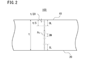
- Figure 2 is a cross sectional view of a UOE pipe.
- Figure 3 is a diagram showing the relationship between a difference value delta of the hardness of the outer and inner surface layers of a steel plate for UOE steel pipe and the hardness of the outer and inner surface layers of a UOE steel pipe and t/D (wall thickness/outside diameter) of the UOE steel pipe.
- the present inventors investigated and studied the HIC resistance of high-strength UOE steel pipes for line pipe. As a result, the inventors obtained the following findings.
- a steel plate in which center segregation is suppressed has excellent HIC resistance even when it has high strength.
- HIC may sometimes occur in the case where a UOE steel pipe is manufactured from such a steel plate by carrying out pipe-making processes such as C press forming, U press forming and O press forming.
- FIG. 1 is a diagram of the hardness distribution in the cross section of a UOE steel pipe in a radial direction (a wall thickness direction).
- Figure 1 was obtained by the following method. Two steel plates having almost constant hardness in the through-thickness direction and having hardnesses different from each other were prepared. The chemical compositions of these steel plates are in the range of the chemical composition of this embodiment, which will be described later, and the tensile strength was not less than 625 MPa. Each steel plate was subjected to C press forming, U press forming, and O press forming and two UOE steel pipes were produced (mark I, mark II).
- the triangle shape mark in the figure 1 indicates the test result of the UOE steel pipe of mark I
- the diamond shape mark indicates the test result of the UOE steel pipe of mark II.
- the hardness of the center portion of the wall thickness in the radial direction (wall thickness direction) of the steel pipes was almost the same as the hardness of the steel plates before pipe-making.
- the hardness increased from the center portion of the wall thickness toward the inner surface and the outer surface.
- maximum values of hardness of the inner surface layer including the inner surface and of the outer surface layer including the outer surface exceeded 255 HV10.
- the occurrence of HIC is related to the hydrogen concentration (C0) in steel and the hydrogen concentration (Cth) which is allowed until the occurrence of HIC in steel.
- the hydrogen concentrations Cth allowed in the outer and inner surface layers are low compared to those of portions other than the outer and inner surface layers and the center portion of the wall thickness. This is because the outer and inner surface layers include floating inclusions (for example, oxide-based inclusions, such as Al 2 O 3 and CaO) generated during continuous casting and because these floating inclusions lower the allowable hydrogen concentration Cth (hereinafter referred to as the allowable hydrogen concentration).
- the allowable hydrogen concentration Cth in the center portion of the wall thickness is lower than the allowable hydrogen concentration Cth of the outer and inner surface layers. This is because in the center portion of the wall thickness, more carbonitrides are generated and grow due to center segregation and because these carbonitrides increase HIC sensitivity more than oxide-based inclusions do. Furthermore, because in the center portion of the wall thickness hydrogen is apt to condense due to center segregation, the hydrogen concentration C0 in the center portion of the wall thickness is higher than in portions other than the center portion of the wall thickness. That is, from the standpoint of the hydrogen concentrations C0 and Cth, the HIC sensitivity is highest in the center portion of the wall thickness and is second highest in the portions of the outer and inner surface layers.
- an upper limit to the hardness in the center portion of the wall thickness is set at 248 HV10 and an upper limit to the hardness of the outer and inner surface layers is set at 255 HV10, then the occurrence of HIC is suppressed even in UOE steel pipes having strength of not less than X80 grade of API Standard.
- the UOE steel pipe for line pipe in this embodiment was completed on the basis of the above-described findings. Details of the UOE steel pipe for line pipe in this embodiment will be described below.
- the UOE steel pipe for line pipe in this embodiment has the following chemical composition. As described above, % related to elements means mass%.
- C 0.01 to 0.1% Carbon (C) increases the strength of steel. However, if the C content is too high, the chemical composition of the steel is included in the peritectic region. For this reason, it becomes difficult to produce steel by continuous casting. Therefore, the C content is 0.01 to 0.1%.
- the lower limit to the C content is preferably higher than 0.01%, more preferably 0.03%, and still more preferably 0.04%.
- the upper limit to the C content is preferably less than 0.1%, more preferably 0.07%, and still more preferably 0.06%.
- Si 0.01 to 0.5% Silicon (Si) deoxidizes steel. However, if the Si content is too high, toughness decreases. Therefore, the Si content is 0.01 to 0.5%.
- the lower limit to the Si content is preferably higher than 0.01%, more preferably 0.03%, and still more preferably 0.05%.
- the upper limit to the Si content is preferably less than 0.5%, more preferably 0.40%, and still more preferably 0.35%.
- Mn 1.0 to 1.7%
- Mn Manganese
- the lower limit to the Mn content is preferably higher than 1.0%, more preferably 1.1%, and still more preferably 1.2%.
- the upper limit to the Mn content is preferably less than 1.7%, more preferably 1.6%, and still more preferably 1.5%.
- Phosphorus (P) is an impurity. Like Mn, P is apt to segregate normally in the center portion of the wall thickness and hardens a normally segregated part. The hardening of a normally segregated part induces HIC. Therefore, it is preferred that the P content be low.
- the P content is not more than 0.015%.
- the P content is preferably less than 0.015%, more preferably not more than 0.010%.
- S is an impurity. S forms MnS. MnS provides an initiation point of HIC. Therefore, it is preferred that the S content be as low as possible.
- the S content is not more than 0.002%.
- the S content is preferably less than 0.002%, more preferably not more than 0.001%.
- Chromium (Cr) increases the strength and toughness of steel. However, if the Cr content is too high, weldability decreases and weld cracking becomes apt to occur. Therefore, the Cr content is 0.01 to 0.45%.
- the lower limit to the Cr content is preferably higher than 0.01%, more preferably 0.05%, and still more preferably 0.1%.
- the upper limit to the Cr content is preferably less than 0.45%, more preferably 0.35%, and still more preferably 0.3%.
- Mo 0.03 to 0.5% Molybdenum (Mo) increases the hardenability of steel and increases the strength of steel. Furthermore, because the microsegregation of Mo is not apt to occur, the occurrence of HIC caused by center segregation is suppressed. However, because Mo is expensive, the manufacturing cost increases if Mo is contained excessively. Therefore, the Mo content is 0.03 to 0.5%.
- the lower limit to the Mo content exceeds preferably 0.03%, is more preferably 0.05%, and still more preferably 0.1%.
- the upper limit to the Mo content is preferably less than 0.5%, more preferably 0.4%, and still more preferably 0.3%.
- Al 0.005 to 0.05%
- Aluminum (Al) deoxidizes steel. However, if the Al content is too high, cleanliness and toughness of steel decrease. Therefore, the Al content is 0.005 to 0.05%.
- the lower limit to the Al content is preferably higher than 0.005%, more preferably 0.01%, and still more preferably 0.015%.
- the upper limit to the Al content is preferably less than 0.05%, more preferably 0.045%, and still more preferably 0.04%.
- the Al content in this embodiment means the content of sol. Al (acid-soluble Al).
- Ca 0.0005% to 0.0050%
- Calcium (Ca) controls the shape of MnS, which provides an initiation point of HIC, to a spherical shape and suppresses the occurrence of HIC. Furthermore, Ca forms CaS and suppresses the generation of MnS.
- the Ca content is 0.0005% to 0.0050%.
- the lower limit to the Ca content exceeds preferably 0.0005%, is more preferably 0.001% and still more preferably 0.0015%.
- the upper limit to the Ca content is preferably less than 0.0050%, more preferably 0.0040%, and still more preferably 0.0030%.
- Ti 0.005% to 0.03% Titanium (Ti) combines with nitrogen (N) to form TiN. TiN suppresses the coarsening of austenite grains during slab heating and the HAZ (heat-affected zone) and increases the low-temperature toughness of the base metal and the HAZ. However, if the Ti content is too high, TiN is generated excessively, resulting in a decrease in toughness. Therefore, the Ti content is 0.005 to 0.03%.
- the lower limit to the Ti content exceeds preferably 0.005%, is more preferably 0.008%, and still more preferably 0.01%.
- the upper limit to the Ti content is preferably less than 0.03%, more preferably 0.025%, and still more preferably 0.02%.
- N 0.001 to 0.005%
- Nitrogen (N) combines with the above-described Ti to form TiN, and increases the low-temperature toughness of the base metal and the HAZ. However, if the N content is too high, TiN is formed excessively and toughness decreases. Therefore, the N content is 0.001 to 0.005%.
- the lower limit to the N content is preferably higher than 0.001%, more preferably 0.0015%, and still more preferably 0.002%.
- the upper limit to the N content is preferably less than 0.005%, more preferably 0.0045%, and still more preferably 0.004%.
- the balance of the chemical composition of the UOE steel pipe in this embodiment consists of Fe and impurities.
- the impurities mentioned here refer to the elements which are mixed in from ores and scraps used as the raw materials for steel or from the environment and the like of manufacturing processes.
- the UOE steel pipe in this embodiment may further contain, in place of part of Fe, at least one selected from the group consisting of Cu, Ni, Nb, and V. These elements are all optional elements and increase the strength of steel.
- Cu not more than 0.5% Copper (Cu) is an optional element. Cu increases the hardenability of steel and increases the strength of steel. If even a small amount of Cu is contained, the above-described effects are obtained. However, if the Cu content is too high, the hot workability of steel decreases. Furthermore, the surfaces of a slab become apt to crack during continuous casting. Therefore, the Cu content is not more than 0.5%.
- the lower limit to the Cu content is preferably 0.05%, more preferably higher than 0.05%, and still more preferably 0.1%.
- the upper limit to the Cu content is preferably less than 0.5%, more preferably 0.4%, and still more preferably 0.3%.
- Ni not more than 0.5%
- Nickel (Ni) is an optional element. Ni increases the strength of steel by solid-solution strengthening. Furthermore, Ni increases the toughness of steel. If even a small amount of Ni is contained, the above-described effects are obtained. However, if the Ni content is too high, the weldability of steel decreases. Therefore, the Ni content is not more than 0.5%.
- the lower limit to the Ni content is preferably 0.05%, more preferably higher than 0.05%, and still more preferably 0.1%.
- the upper limit to the Ni content is preferably less than 0.5%, more preferably 0.4%, and still more preferably 0.3%.
- Niobium (Nb) is an optional element. Nb forms carbides in steel. Nb carbides reduce the grain size of steel, increasing the strength and toughness of steel. If even a small amount of Nb is contained, the above-described effects are obtained. However, if the Nb content is too high, the toughness of weld zones decreases. Therefore, the Nb content is not more than 0.05%.
- the lower limit to the Nb content is preferably 0.005%, more preferably higher than 0.005, and still more preferably 0.01%.
- the upper limit to the Nb content is preferably less than 0.05%, more preferably 0.045%, and still more preferably 0.04%.
- V Not more than 0.10% Vanadium (V) is an optional element. V dissolves in steel in a solid solution state or forms carbonitrides in steel, increasing the strength of steel. If even a small amount of V is contained, the above-described effect is obtained. However, if the V content is too high, V carbonitrides coarsen in the HAZ and HAZ toughness decreases. Therefore, the V content is not more than 0.10%.
- the lower limit to the V content is preferably 0.005%, more preferably higher than 0.005%, and still more preferably 0.01%.
- the upper limit to the V content is preferably less than 0.10%, more preferably 0.08%, and still more preferably 0.07%.
- the structure of the UOE steel pipe in this embodiment is a bainite single phase.
- the "bainite single phase” in this specification may contain quasi-polygonal ferrite, granular bainitic ferrite, and bainitic ferrite.
- the structure of the UOE steel pipe may contain M-A constituent (MA), martensite, and pearlite, the total content rate of MA, martensite, and pearlite is not more than 2% in terms of area fraction.
- MA, martensite, and pearlite are called “hardened structures.” Therefore, in this specification, the "bainite single phase” may contain hardened structures in amounts of not more than 2% in area fraction.
- the structure of the UOE steel pipes is identified, for example, by the following method of microstructure observation and test.
- the portion at a depth of 1/4 of the wall thickness from the outer surface is etched with nital and the like. Any of 10 to 30 fields of vision (each field of vision: 8 to 24 mm 2 ) in the etched 1/4 portion of the wall thickness is observed.
- An optical microscope with a magnification of 200 times is used in the observation. Bainite, MA, martensite, and pearlite can be recognized by etching. Therefore, the area fraction of the bainite in each field of vision and the area fraction of other structures (hardened structures) can be found.
- the value obtained by averaging the area fraction of the hardened structures in each field of vision is defined as the area fraction (%) of hardened structures.
- the structure of the UOE steel pipe may further contain inclusions and precipitates. Bainite shingle phase does not contain polygonal ferrite.
- the structure of the UOE steel pipe of this embodiment is a bainite single phase, and the area fraction of hardened structures, such as MA, martensite, and pearlite, is low. For this reason, the UOE steel pipe is excellent in HIC resistance although the steel pipe has high strength.
- the hardness of the outer and inner surface layers is 200 to 255 in terms of HV10, and the hardness of the center portion of the wall thickness is 200 to 248 in terms of HV10.
- the condition that this upper limit to the hardness of the center portion of the wall thickness is limited to be lower than the upper limit to the hardness of the outer and inner surface layers was found by the result of a study carried out by the inventors by trial and error.
- FIG. 2 shows the cross sectional view of a UOE steel pipe (i.e., a sectional view obtained by cutting the UOE steel pipe in the radial direction).
- a UOE steel pipe 100 is divided into 20 equal parts in the direction of wall thickness t.
- the range from an outer surface 10 of a UOE steel pipe 100 to t/5 in the direction of an inner surface 20 is defined as an outer surface layer OL.
- the range from an inner surface 20 to t/5 in the direction of an outer surface 10 is defined as an inner surface layer IL.
- the range of t/10 in the wall thickness t direction around a center position Pc of the wall thickness t is defined as a center portion of the wall thickness CN.
- the top of the cross section of the UOE steel pipe is assumed to be an origin (0 degree).
- the position at clockwise 90 degrees (the 90-degree position), the outer surface layer OL in the position at 180 degrees (the 180-degree position), the inner surface layer IL, and the center portion of the wall thickness CN are identified.
- the outer surface layer OL, the inner surface layer IL, and the center portion of the wall thickness CN are all the base metal and do not provide a weld zone.
- the Vickers hardness test in accordance with JIS Z2244 (2009) is carried out in the radial direction (in the wall thickness t direction) with a 0.5-mm pitch.
- a dent formed by the Vickers indenter covers a plurality of crystal grains.
- a maximum value and a minimum value are identified in a plurality of values obtained by the Vickers hardness test, and these are defined as the hardness of the outer and inner surface layers OL and IL (a maximum value and a minimum value).
- a maximum value and a minimum value are identified in a plurality of values obtained by the Vickers hardness test, and these are defined as the hardness of the center portion of the wall thickness CN (a maximum value and a minimum value).
- maximum values of the hardness of the outer and inner surface layers OL and IL defined by the above-described method are not more than 255 HV10. Minimum values of the hardness of the outer and inner surface layers OL and IL are not less than 200 HV10. Similarly, maximum values of the hardness of the center portion of the wall thickness CN are not more than 248 HV10. Minimum values of the hardness of the center portion of the wall thickness CN are not less than 200 HV10. To sum up, the hardness of the outer and inner surface layers OL and IL is 200 to 255 HV10, and the hardness of the center portion of the wall thickness CN is 200 to 248 HV10.
- a slab is produced from a molten steel having the above-described chemical composition by the continuous casting method (the continuous casting process).
- a steel plate for UOE steel pipe is produced by rolling the produced slab (the rolling process).
- a UOE steel pipe is produced by working the produced steel plate (the pipe-making process).
- a molten steel having above-described chemical composition is produced by refining steel.
- a slab is produced from the produced molten steel by the continuous casting method.
- the slab is reduced in the vicinity of a final solidification position during continuous casing.
- appropriate water cooling conditions and casting speed are selected so that remarkable solidification nonuniformity does not occur in the casting width direction, the casting length direction.
- the segregation of Mn, P, S and the like in the center portion of the wall thickness is suppressed.
- the slab produced in the continuous casting process is heated in a heating furnace (the heating process).
- the heated slab is rolled on a rolling mill to produce a steel plate (the working process).
- the steel plate after rolling is immediately cooled (the cooling process).
- annealing is carried out as required (the annealing process). If the rolling process is carried out on the basis of the heating process, working process, cooling process, and annealing process which are described below, a UOE steel pipe obtains the above-described structure, hardness and tensile strength.
- the slab heating temperature in the heating furnace is set at 1000 to 1250 o C. If the heating temperature is too high, it is impossible to reduce the size of crystal grains because austenite grains coarsen. For this reason, HIC resistance decreases. On the other hand, if the heating temperature is too low, it is impossible to cause the Nb carbonitrides formed in the slab during continuous casting to dissolve in a solid solution state, and HIC resistance decreases. Furthermore, it becomes difficult to obtain the grain refinement of the crystal grains during rolling and precipitation strengthening after rolling. By setting the heating temperature at 1000 to 1250 o C, it becomes possible to suppress the coarsening of austenite grains and to cause Nb to dissolve in a solid solution state.
- the heating temperature T ( o C) satisfies Expression (1) below:
- the content of each element (mass%) is substituted into each chemical symbol in Expression (1).
- Nb in steel is apt to dissolve in a solid solution state.
- Soaking may be carried out for the slab.
- the segregation in the center portion of the wall thickness is suppressed.
- Preferred soaking temperatures are 1000 to 1300 o C, and the soaking time is 20 to 50 hours. In this case, the segregation of C, Mn, P, S and the like is suppressed.
- the surface temperature of the workpiece material during rolling be not less than the A r3 point.
- the rolling reduction (%) is not specifically limited. In general, the rolling reduction is not less than 50%.
- the steel plate is cooled immediately after the completion of rolling. That is, accelerated cooling is carried out. It is preferred that the surface temperature of the steel plate at the start of cooling be not less than the A r3 point. If the surface temperature of the steel plate is less than the A r3 point, ferrite is generated and the discharge of carbon is started. HIC resistance decreases because hardened structures become apt to be formed due to the carbon discharged from the ferrite phase.
- the cooling rate after rolling be 10 to 40 o C/sec.
- water cooling is carried out. If the cooling rate is too low, the diffusion of C and P is promoted. Diffused elements precipitate at the grain boundaries or on inclusions. On the other hand, because if the cooling rate is too high, hardening is carried out excessively and hardened structures are generated, with the result that the structure of steel does not easily become a bainite shingle phase.
- Preferable cooling stop temperatures are 350 to 600 o C. That is, when the surface temperature of the steel plate has become 350 to 600 o C, the cooling at the above-described cooling rates is stopped. The diffusion of C and P is promoted in the case where the steel plate is allowed to cool immediately without cooling after rolling at the above-described cooling rates.
- Natural cooling is preferable after the cooling at the above-described cooling rates is stopped at the cooling stop temperatures. This is because toughness is increased due to the annealing effect during natural cooling and the occurrence of HIC can be suppressed.
- t is the wall thickness (mm) of a UOE steel pipe to be produced
- D is the diameter (mm) of the UOE steel pipe to be produced.
- Figure 3 is a diagram showing the relationship between a difference value delta of the hardness of the outer and inner surface layers of a steel plate and the hardness of the outer and inner surface layers of a UOE steel pipe and t/D (%) of the UOE steel pipe, which was obtained when the UOE steel pipe was produced from the steel plate having the above-described chemical composition.
- Figure 3 was obtained by the following method.
- a plurality of steel plates having the above-described chemical composition were produced by the above-described manufacturing method.
- a plurality of UOE steel pipes having different t/D were produced from the produced steel plates by the pipe-making process which will be described later.
- the pipe expansion rate during pipe-making was 0.7 to 1.2%.
- maximum values of the hardness of the outer and inner surface layers were found in accordance with the above-described Vickers hardness test.
- the larger t/D the larger the difference value delta. More specifically, as indicated by the curve C0 in Figure 3, the hardness of the outer and inner surface layers increases remarkably in a manner represented by a quadric function as t/D increases. Hardness and tensile strength are substantially directly proportional to each other. Specifically, when hardness increases, tensile strength also increases in a manner represented by a linear function. Expression (4) was obtained on the basis of the above-described findings.
- the tensile strength TS0 of a steel plate after the cooling process does not satisfy Expression (4), it is ensured that the tensile strength TS0 of the steel plate satisfies Expression (4) by carrying out annealing less than the A c1 point.
- Preferable annealing temperatures are 350 to 600 o C, and preferable annealing time is 30 to 90 minutes.
- the produced steel plate is formed to produce an open pipe by using a C press, a U press, an O press and the like. Subsequently, both longitudinal end surfaces of the open pipe are welded by the submerged arc welding process and the like to form a welded steel pipe.
- the produced welded steel pipe is subjected to pipe expanding to produce a UOE steel pipe.
- the chemical compositions of the steel grades A to D, F and G in Table 1 were in the range of the chemical composition of the UOE steel pipe of the present invention.
- the Mn content, P content and S content of the steel grade E exceeded the upper limits to the Mn content, P content and S content of the present invention.
- the UOE steel pipes with the marks 1 to 18 shown in Table 2 were produced from a plurality of slabs of the steel grades A to H.
- the slabs with all of the marks were heated in a heating furnace.
- the heating temperatures ( o C) were as shown in Table 2.
- the slabs after heating were rolled to produce steel plates.
- Each of the steel plates was water-cooled immediately after rolling. Cooling rates by water cooling were in the range of 10 to 40 o C/sec.
- the cooling start temperatures ( o C) of the steel plates with all of the marks were as shown in Table 2. Furthermore, water cooling was stopped at the cooling stop temperatures ( o C) shown in Table 2. The steel plates after the stop of water cooling were allowed to cool.
- the yield strength TS0 of the steel plates after cooling exceeded the value F1.
- the steel plates of the marks 8 to 10 were subjected to annealing.
- the annealing temperatures were in the range of 350 to 600 o C and the annealing time was 30 to 90 minutes.
- the tensile strength TS0 (MPa) of the marks 8 to 10 in Table 2 are values obtained before annealing.
- the tensile strength Th0 (MPa) of the mark 8 to 10 after annealing were not more than the value of F1.
- the steel plates of marks other than the marks 8 to 10 and 17 were not subjected to annealing.
- the manufacturing conditions other than whether or not annealing was carried out and the steel grade were the same.
- the manufacturing conditions other than whether or not annealing was carried out and the steel grade were the same.
- annealing was not carried out.
- UOE steel pipes were produced by subjecting the steel plates of all marks to pipe-making by the above-described method.
- the wall thickness t (mm) and outside diameter D (mm) of the produced UOE steel pipes were measured.
- Tensile test specimens were taken from the UOE steel pipes and the tensile test was carried out at normal temperature (25 o C) to find the yield strength YS (MPa) and tensile strength TS (MPa).
- Test specimens (thickness: 10 mm, width: 20 mm, length: 100 mm) were taken from the UOE steel pipes of all marks. The HIC test was conducted with the aid of the taken test specimens. The test specimens were subjected to the NACE test specified in NACE TM-02-84 as the HIC test, and by the ultrasonic flaw detection method a judgment was made as to whether or not HIC occurred in each of the test specimens after the test.
- Table 2 shows the test results.
- the "min” column of “Outer and inner surface layers” of “Vickers hardness” of Table 2 indicates a minimum value (HV10) of the hardness of the outer and inner surface layers of a UOE steel pipe of a corresponding mark.
- the “max” column indicates a maximum value (HV10) of the hardness of the outer and inner surface layers of a UOE steel pipe.
- the “min” column of “Center portion of wall thickness” of "Vickers hardness” indicates a minimum value (HV10) of the hardness of the center portion of the wall thickness of a UOE steel pipe
- the “max” column indicates a maximum value of the hardness of the center portion of the wall thickness.
- the chemical compositions of the marks 1 to 12 were in the range of the present invention. Furthermore, the tensile strength was not less than 625 MPa and the UOE steel pipes had strength of not less than X80 grade of API standard. Furthermore, the maximum values and minimum values of the hardness of the outer and inner surface layers of the UOE steel pipes were all in the range (200 to 255) of the present invention. Also the maximum values and minimum values of the hardness of the center portion of the wall thickness were in the range (200 to 248) of the present invention. For this reason, HIC did not occur in the UOE steel pipes of the marks 1 to 12.
Landscapes
- Chemical & Material Sciences (AREA)
- Engineering & Computer Science (AREA)
- Mechanical Engineering (AREA)
- Materials Engineering (AREA)
- Metallurgy (AREA)
- Organic Chemistry (AREA)
- Physics & Mathematics (AREA)
- Thermal Sciences (AREA)
- Crystallography & Structural Chemistry (AREA)
- Heat Treatment Of Steel (AREA)
Abstract
L'invention porte sur un tuyau en acier UOE pour tube de canalisation ayant une excellente résistance à la fissuration provoquée par l'hydrogène (HIC) même lorsqu'il a une résistance élevée. Le tuyau en acier UOE pour tube de canalisation dans ce mode de réalisation contient, en % en masse, 0,01 à 0,1 % de C, 0,01 à 0,5 % de Si, 1,0 à 1,7 % de Mn, au maximum 0,015 % de P, au maximum 0,002 % de S, 0,01 à 0,45 % de Cr, 0,03 à 0,5 % de Mo, 0,005 à 0,05 % d'Al, 0,0005 à 0,0050 % de Ca, 0,001 à 0,005 % de N et 0,005 à 0,03 % de Ti, le reste étant du Fe et des impuretés, et il a une structure à une seule phase bainitique. Dans ce tuyau en acier UOE, la dureté de couches de surface externe et interne du tuyau en acier UOE est de 200 à 255 en termes de HV10, la dureté d'une partie centrale dans l'épaisseur de la paroi du tuyau en acier UOE est de 200 à 248 en termes de HV10 et la résistance à la traction est supérieure ou égale à 625 MPa.
Applications Claiming Priority (2)
| Application Number | Priority Date | Filing Date | Title |
|---|---|---|---|
| JP2012-020614 | 2012-02-02 | ||
| JP2012020614A JP5565420B2 (ja) | 2012-02-02 | 2012-02-02 | ラインパイプ用uoe鋼管 |
Publications (1)
| Publication Number | Publication Date |
|---|---|
| WO2013114519A1 true WO2013114519A1 (fr) | 2013-08-08 |
Family
ID=47605707
Family Applications (1)
| Application Number | Title | Priority Date | Filing Date |
|---|---|---|---|
| PCT/JP2012/008456 Ceased WO2013114519A1 (fr) | 2012-02-02 | 2012-12-28 | Tuyau en acier uoe pour tube de canalisation |
Country Status (2)
| Country | Link |
|---|---|
| JP (1) | JP5565420B2 (fr) |
| WO (1) | WO2013114519A1 (fr) |
Cited By (6)
| Publication number | Priority date | Publication date | Assignee | Title |
|---|---|---|---|---|
| EP3088553A4 (fr) * | 2014-02-04 | 2017-08-23 | Nippon Steel & Sumitomo Metal Corporation | Tuyau en acier |
| US10207328B2 (en) | 2014-12-05 | 2019-02-19 | Jfe Steel Corporation | Alloy steel powder for powder metallurgy, and sintered body |
| EP3546610A4 (fr) * | 2017-03-29 | 2020-04-29 | Nippon Steel Corporation | Tuyau en acier soudé par résistance électrique de type brut de laminage pour tuyaux de canalisation |
| EP3686305A4 (fr) * | 2017-09-19 | 2021-01-27 | Nippon Steel Corporation | Tube en acier et plaque d'acier |
| EP4006180A4 (fr) * | 2019-07-31 | 2022-10-12 | JFE Steel Corporation | Feuille d'acier à haute résistance pour tuyau de canalisation résistant à l'acidité, procédé de fabrication correspondant et tuyau d'acier à haute résistance utilisant une feuille d'acier à haute résistance pour tuyau de canalisation résistant à l'acidité |
| EP4015669A4 (fr) * | 2019-12-07 | 2022-12-21 | Jiangyin Xingcheng Special Steel Works Co., Ltd | Acier de canalisation résistant aux hic et résistant aux déformations importantes et son procédé de préparation |
Citations (4)
| Publication number | Priority date | Publication date | Assignee | Title |
|---|---|---|---|---|
| JPH05271766A (ja) | 1992-03-30 | 1993-10-19 | Nippon Steel Corp | 耐水素誘起割れ性の優れた高強度鋼板の製造方法 |
| JP2009235524A (ja) * | 2008-03-27 | 2009-10-15 | Jfe Steel Corp | 靭性および変形能に優れた板厚:25mm以上の高強度鋼管用鋼材およびその製造方法 |
| WO2011142172A1 (fr) * | 2010-05-12 | 2011-11-17 | 株式会社神戸製鋼所 | Plaque en acier épaisse hautement résistante à caractéristiques à masse tombante excellentes |
| EP2407570A1 (fr) * | 2009-03-12 | 2012-01-18 | Sumitomo Metal Industries, Ltd. | Feuille d'acier épais résistant de hic et tuyau en acier fabriqué selon le procédé uoe |
Family Cites Families (5)
| Publication number | Priority date | Publication date | Assignee | Title |
|---|---|---|---|---|
| JPH06293919A (ja) * | 1993-04-08 | 1994-10-21 | Nippon Steel Corp | 耐サワー性および低温靭性に優れた高張力鋼板の製造方法 |
| JP3502691B2 (ja) * | 1995-04-12 | 2004-03-02 | 新日本製鐵株式会社 | 耐水素誘起割れ性および耐硫化物応力腐食割れ性に優れたフィッティング材およびその製造方法 |
| JP4305216B2 (ja) * | 2004-02-24 | 2009-07-29 | Jfeスチール株式会社 | 溶接部の靭性に優れる耐サワー高強度電縫鋼管用熱延鋼板およびその製造方法 |
| JP5194807B2 (ja) * | 2008-01-09 | 2013-05-08 | Jfeスチール株式会社 | 高降伏強度・高靭性厚鋼板の製造方法 |
| JP5181697B2 (ja) * | 2008-01-25 | 2013-04-10 | Jfeスチール株式会社 | 耐pwht特性に優れた高強度鋼板およびその製造方法 |
-
2012
- 2012-02-02 JP JP2012020614A patent/JP5565420B2/ja not_active Expired - Fee Related
- 2012-12-28 WO PCT/JP2012/008456 patent/WO2013114519A1/fr not_active Ceased
Patent Citations (4)
| Publication number | Priority date | Publication date | Assignee | Title |
|---|---|---|---|---|
| JPH05271766A (ja) | 1992-03-30 | 1993-10-19 | Nippon Steel Corp | 耐水素誘起割れ性の優れた高強度鋼板の製造方法 |
| JP2009235524A (ja) * | 2008-03-27 | 2009-10-15 | Jfe Steel Corp | 靭性および変形能に優れた板厚:25mm以上の高強度鋼管用鋼材およびその製造方法 |
| EP2407570A1 (fr) * | 2009-03-12 | 2012-01-18 | Sumitomo Metal Industries, Ltd. | Feuille d'acier épais résistant de hic et tuyau en acier fabriqué selon le procédé uoe |
| WO2011142172A1 (fr) * | 2010-05-12 | 2011-11-17 | 株式会社神戸製鋼所 | Plaque en acier épaisse hautement résistante à caractéristiques à masse tombante excellentes |
Cited By (6)
| Publication number | Priority date | Publication date | Assignee | Title |
|---|---|---|---|---|
| EP3088553A4 (fr) * | 2014-02-04 | 2017-08-23 | Nippon Steel & Sumitomo Metal Corporation | Tuyau en acier |
| US10207328B2 (en) | 2014-12-05 | 2019-02-19 | Jfe Steel Corporation | Alloy steel powder for powder metallurgy, and sintered body |
| EP3546610A4 (fr) * | 2017-03-29 | 2020-04-29 | Nippon Steel Corporation | Tuyau en acier soudé par résistance électrique de type brut de laminage pour tuyaux de canalisation |
| EP3686305A4 (fr) * | 2017-09-19 | 2021-01-27 | Nippon Steel Corporation | Tube en acier et plaque d'acier |
| EP4006180A4 (fr) * | 2019-07-31 | 2022-10-12 | JFE Steel Corporation | Feuille d'acier à haute résistance pour tuyau de canalisation résistant à l'acidité, procédé de fabrication correspondant et tuyau d'acier à haute résistance utilisant une feuille d'acier à haute résistance pour tuyau de canalisation résistant à l'acidité |
| EP4015669A4 (fr) * | 2019-12-07 | 2022-12-21 | Jiangyin Xingcheng Special Steel Works Co., Ltd | Acier de canalisation résistant aux hic et résistant aux déformations importantes et son procédé de préparation |
Also Published As
| Publication number | Publication date |
|---|---|
| JP2013159793A (ja) | 2013-08-19 |
| JP5565420B2 (ja) | 2014-08-06 |
Similar Documents
| Publication | Publication Date | Title |
|---|---|---|
| EP3042976B1 (fr) | Tôle d'acier pour tube de canalisation à paroi épaisse et à haute résistance mécanique ayant d'excellentes caracteristiques de résistance à la corrosion et à l'affaissement, et une ductilité aux basses températures, ainsi que tube de canalisation | |
| JP5561119B2 (ja) | 高圧縮強度耐サワーラインパイプ用溶接鋼管及びその製造方法 | |
| CN110462080B (zh) | 耐酸性管线管用高强度钢板及其制造方法和使用耐酸性管线管用高强度钢板的高强度钢管 | |
| KR101511617B1 (ko) | 높은 압축 강도를 갖는 라인파이프용 용접 강관의 제조 방법 | |
| KR101699818B1 (ko) | 높은 압축 강도 및 인성을 갖는 라인파이프용 용접 강관 | |
| AU2003264947B2 (en) | High strength seamless steel pipe excellent in hydrogen-induced cracking resistance and its production method | |
| US9932651B2 (en) | Thick-walled high-strength seamless steel pipe with excellent sour resistance for pipe for pipeline, and process for producing same | |
| JP4969915B2 (ja) | 耐歪時効性に優れた高強度ラインパイプ用鋼管及び高強度ラインパイプ用鋼板並びにそれらの製造方法 | |
| JP6665525B2 (ja) | 低温用h形鋼及びその製造方法 | |
| US20140227126A1 (en) | High strength steel pipe for line pipe superior in low temperature toughness and high strength steel plate for line pipe and methods of production of the same | |
| JP5782827B2 (ja) | 高圧縮強度耐サワーラインパイプ用鋼管及びその製造方法 | |
| JP6048436B2 (ja) | 調質高張力厚鋼板及びその製造方法 | |
| CN104024461A (zh) | 抗氢诱发裂纹性优良的高强度管道用钢管和其所使用的高强度管道用钢板、以及它们的制造方法 | |
| CN109563587B (zh) | 无缝钢管及其制造方法 | |
| WO2013114519A1 (fr) | Tuyau en acier uoe pour tube de canalisation | |
| WO2014192251A1 (fr) | Tube en acier sans soudure destiné à un tube de canalisation utilisé dans un environnement acide | |
| JP2023022159A (ja) | 耐水素誘起割れ(hic)性が強化されたx-65グレードのapi 5l psl-2仕様に適合する鋼組成物及びその鋼の製造方法 | |
| EP3330398B1 (fr) | Tuyau en acier pour un tuyau de canalisation et procédé permettant de produire ce dernier | |
| CN114846163B (zh) | 钢板和钢管 | |
| JP6866855B2 (ja) | 耐サワーラインパイプ用高強度鋼板の製造方法、及び耐サワーラインパイプ用高強度鋼板、並びに耐サワーラインパイプ用高強度鋼板を用いた高強度鋼管 | |
| CN111655872B (zh) | 管线管用钢材及其制造方法以及管线管的制造方法 | |
| JP2017186594A (ja) | 低温用h形鋼及びその製造方法 | |
| JP6819835B1 (ja) | ラインパイプ用鋼材およびその製造方法ならびにラインパイプおよびその製造方法 | |
| RU2574924C1 (ru) | Высокопрочная стальная труба и высокопрочный стальной лист, обладающие превосходной деформируемостью и низкотемпературной ударной вязкостью, и способ изготовления стального листа | |
| JP2024530039A (ja) | 耐摩耗性に優れた熱延鋼板、鋼管及びこれらの製造方法 |
Legal Events
| Date | Code | Title | Description |
|---|---|---|---|
| 121 | Ep: the epo has been informed by wipo that ep was designated in this application |
Ref document number: 12818940 Country of ref document: EP Kind code of ref document: A1 |
|
| NENP | Non-entry into the national phase |
Ref country code: DE |
|
| 122 | Ep: pct application non-entry in european phase |
Ref document number: 12818940 Country of ref document: EP Kind code of ref document: A1 |