WO2013114597A1 - Dispositif de traitement audio - Google Patents
Dispositif de traitement audio Download PDFInfo
- Publication number
- WO2013114597A1 WO2013114597A1 PCT/JP2012/052323 JP2012052323W WO2013114597A1 WO 2013114597 A1 WO2013114597 A1 WO 2013114597A1 JP 2012052323 W JP2012052323 W JP 2012052323W WO 2013114597 A1 WO2013114597 A1 WO 2013114597A1
- Authority
- WO
- WIPO (PCT)
- Prior art keywords
- pass filter
- housing
- microphone
- processing apparatus
- band
- Prior art date
- Legal status (The legal status is an assumption and is not a legal conclusion. Google has not performed a legal analysis and makes no representation as to the accuracy of the status listed.)
- Ceased
Links
Images


Classifications
-
- H—ELECTRICITY
- H04—ELECTRIC COMMUNICATION TECHNIQUE
- H04R—LOUDSPEAKERS, MICROPHONES, GRAMOPHONE PICK-UPS OR LIKE ACOUSTIC ELECTROMECHANICAL TRANSDUCERS; ELECTRIC HEARING AIDS; PUBLIC ADDRESS SYSTEMS
- H04R1/00—Details of transducers, loudspeakers or microphones
- H04R1/10—Earpieces; Attachments therefor ; Earphones; Monophonic headphones
- H04R1/1058—Manufacture or assembly
- H04R1/1075—Mountings of transducers in earphones or headphones
-
- H—ELECTRICITY
- H04—ELECTRIC COMMUNICATION TECHNIQUE
- H04R—LOUDSPEAKERS, MICROPHONES, GRAMOPHONE PICK-UPS OR LIKE ACOUSTIC ELECTROMECHANICAL TRANSDUCERS; ELECTRIC HEARING AIDS; PUBLIC ADDRESS SYSTEMS
- H04R3/00—Circuits for transducers
- H04R3/04—Circuits for transducers for correcting frequency response
-
- H—ELECTRICITY
- H04—ELECTRIC COMMUNICATION TECHNIQUE
- H04R—LOUDSPEAKERS, MICROPHONES, GRAMOPHONE PICK-UPS OR LIKE ACOUSTIC ELECTROMECHANICAL TRANSDUCERS; ELECTRIC HEARING AIDS; PUBLIC ADDRESS SYSTEMS
- H04R1/00—Details of transducers, loudspeakers or microphones
- H04R1/10—Earpieces; Attachments therefor ; Earphones; Monophonic headphones
- H04R1/1033—Cables or cables storage, e.g. cable reels
-
- H—ELECTRICITY
- H04—ELECTRIC COMMUNICATION TECHNIQUE
- H04R—LOUDSPEAKERS, MICROPHONES, GRAMOPHONE PICK-UPS OR LIKE ACOUSTIC ELECTROMECHANICAL TRANSDUCERS; ELECTRIC HEARING AIDS; PUBLIC ADDRESS SYSTEMS
- H04R25/00—Electric hearing aids
- H04R25/04—Electric hearing aids comprising pocket amplifiers
-
- H—ELECTRICITY
- H04—ELECTRIC COMMUNICATION TECHNIQUE
- H04R—LOUDSPEAKERS, MICROPHONES, GRAMOPHONE PICK-UPS OR LIKE ACOUSTIC ELECTROMECHANICAL TRANSDUCERS; ELECTRIC HEARING AIDS; PUBLIC ADDRESS SYSTEMS
- H04R1/00—Details of transducers, loudspeakers or microphones
- H04R1/10—Earpieces; Attachments therefor ; Earphones; Monophonic headphones
- H04R1/1016—Earpieces of the intra-aural type
-
- H—ELECTRICITY
- H04—ELECTRIC COMMUNICATION TECHNIQUE
- H04R—LOUDSPEAKERS, MICROPHONES, GRAMOPHONE PICK-UPS OR LIKE ACOUSTIC ELECTROMECHANICAL TRANSDUCERS; ELECTRIC HEARING AIDS; PUBLIC ADDRESS SYSTEMS
- H04R2201/00—Details of transducers, loudspeakers or microphones covered by H04R1/00 but not provided for in any of its subgroups
- H04R2201/10—Details of earpieces, attachments therefor, earphones or monophonic headphones covered by H04R1/10 but not provided for in any of its subgroups
- H04R2201/109—Arrangements to adapt hands free headphones for use on both ears
-
- H—ELECTRICITY
- H04—ELECTRIC COMMUNICATION TECHNIQUE
- H04R—LOUDSPEAKERS, MICROPHONES, GRAMOPHONE PICK-UPS OR LIKE ACOUSTIC ELECTROMECHANICAL TRANSDUCERS; ELECTRIC HEARING AIDS; PUBLIC ADDRESS SYSTEMS
- H04R2205/00—Details of stereophonic arrangements covered by H04R5/00 but not provided for in any of its subgroups
- H04R2205/041—Adaptation of stereophonic signal reproduction for the hearing impaired
Definitions
- the present invention relates to a voice processing device.
- An electronic device having a hearing aid function that captures external sound with a microphone, amplifies the sound signal, and outputs the amplified sound signal to a speaker unit of the earphone is known (see Patent Document 1 below).
- This type of electronic device has a pair of earphones connected to the main body, a microphone and a speaker unit built in the earphone, an amplifier that amplifies the electric signal of the microphone built in the earphone, and the volume balance of the speaker is variable.
- An operation unit such as a switch to be adjusted is provided.
- the speaker unit of the handset when the speaker unit of the handset is brought close to the ear, the speaker unit of the handset approaches the microphone in the earphone housing.
- the sound emitted from the speaker unit of the receiver can be amplified and radiated from the speaker unit of the earphone in a natural usage state of the receiver.
- the user may bring the speaker unit of the receiver closer to the earphone microphone.
- a handset or the like comes into contact with the microphone of the earphone to generate a contact sound, which may be amplified by the hearing aid body and radiated from the speaker unit of the earphone.
- Such contact sound is amplified and emitted from the speaker unit, which not only makes the user uncomfortable, but also makes it difficult to hear the conversational sound emitted from the speaker unit of the handset. There was a problem of missing requirements.
- the present invention is an example of a problem to deal with such a problem.
- the microphone in which the microphone is housed in the earphone housing, it is possible to amplify the sound during the phone call without uncomfortable feeling, and to solve the problem that it becomes difficult to hear the voice of the conversation emitted from the handset by the contact sound. What can be done is an object of the present invention.
- an audio processing apparatus comprises at least the following configuration.
- An earphone including a speaker unit and a microphone, and a main body electrically connected to the earphone.
- the main body processes an audio signal collected by the microphone and outputs the processed sound signal to the speaker unit.
- the housing includes a first housing portion for housing the speaker unit and a first housing for housing the microphone. 2, the cord is pulled out from the housing via a cord holding portion of the housing, and the second housing portion extends along the cord holding portion, and the cord holding portion Is disposed at a position facing the microphone hole of the second housing portion.
- FIG. 2A is an explanatory view showing the external structure
- FIG. 2B is a cross-sectional view showing the internal structure.
- FIG. 1 is an explanatory diagram showing the overall configuration of a speech processing apparatus according to an embodiment of the present invention.
- the audio processing device 1 includes an earphone 2 and a main body 3.
- the earphone 2 includes a housing 20 and a cord 21, and the cord 21 is pulled out from the housing 20 via a cord holding portion 21 ⁇ / b> A.
- a connection terminal portion 22 is provided at the end of the cord 21.
- the housing 20 of the earphone 2 is equipped with an auricle connection portion 23A for holding the housing 20 in an airtight manner to the user's ear and an auricle contact portion 23B for bringing the housing 20 into contact with the auricle.
- the earphone 2 includes a speaker unit and a microphone in the housing 20 as described later.
- the earphone 2 includes a single housing 20, and one speaker unit and one omnidirectional microphone are accommodated in the single housing 20.
- the single cord 21 in the earphone 2 accommodates a signal line that electrically connects the speaker unit, the main body 3 and the microphone.
- Examples of the signal line include a conductive wire.
- the cord 21 is composed of a conductive wire and an insulating member (resin member) that insulates the conductive wire from the outside.
- the insulating member has elasticity so that the user can easily use it.
- the cord holding portion 21 ⁇ / b> A is configured by a member (resin member) having bending rigidity that covers the cord 21.
- the member having the bending rigidity has a large bending rigidity with respect to the insulating member of the cord 21.
- the cord 21 vibrates with respect to the user's ear, but the cord holding portion 21 ⁇ / b> A having a large bending rigidity with respect to the cord 21 has a predetermined gap with respect to the microphone hole portion 27. To maintain. That is, since the cord holding portion 21A has a relatively high rigidity, the contact between the cord holding portion 21A and the microphone hole portion 27 is suppressed.
- the main body 3 includes an audio signal processing circuit that is electrically connected to the earphone 2 and processes (including amplification or attenuation) an audio signal collected by the microphone and outputs the processed audio signal to the speaker unit.
- the main body 3 includes a housing (main body housing) 4 that houses an audio signal processing circuit.
- the housing 4 includes a mode changeover switch (changeover switch) 41 that switches modes of use environments to be described later, a volume adjustment wheel 42, and a power supply switch 43 that turns on and off the power supply.
- the changeover switch 41, the volume adjustment wheel 42, and the power switch 43 are disposed in the recess 4 ⁇ / b> B (4 ⁇ / b> B ⁇ b> 1, 4 ⁇ / b> B ⁇ b> 2, 4 ⁇ / b> B ⁇ b> 3) provided on the housing side surface 4 ⁇ / b> A of the main body 3.
- the power switch 43 is arranged so as not to protrude from the housing side surface 4A of the main body 3.
- the main body 3 includes a first light source 4C and a second light source 4D in the housing 4.
- the user selects a mode corresponding to a plurality of different bandpass filters with the mode changeover switch 41 according to the user's own use environment.
- the first light source 4 ⁇ / b> C emits a different emission color corresponding to the mode switched by the mode switch 41.
- the user turns the power of the main body 3 on and off by pressing the power switch 43.
- the second light source 4D is turned on / off according to whether the power source of the main body 3 is turned on or off.
- the main body 3 includes a connected terminal portion 4E to which the connection terminal portion 22 of the earphone 2 is connected.
- the connected terminal portion 4E can connect the attached earphone 2A in place of the earphone 2.
- the attached earphone 2A includes a pair (two) of the above-described housing 20 of the earphone 2, the cord 21, and the like, and includes a housing 20R attached to the user's right ear and a housing 20L attached to the left ear. is doing.
- the connection terminal portion 22A of the attached earphone 2A is for connecting the speaker unit and the microphone in the housings 20R and 20L to the main body 3 by connecting to the connected terminal portion 4E of the main body 3.
- the earphone 2 has a single housing 20 in which one speaker unit and one microphone are housed, and a signal for electrically connecting the speaker unit, the main body 3 and the microphone.
- a single cord 21 that accommodates a wire, and a connection terminal portion 22 that is provided at an end of the cord 21 and connects the signal wire described above to the main body 3 are provided.
- the user can use the speech processing apparatus 1 with one ear released.
- the user can listen to the sound processed (including amplified or attenuated) by the sound processing device 1 with the ear on which the earphone 2 is worn while listening to the environmental sound with the open one ear.
- the sound processed (including amplification or attenuation) can be heard with the same feeling as when the audio processing device 1 is not used.
- the single housing 20 contains an omnidirectional microphone. As a result, even when the single housing 20 of the earphone 2 is attached to one ear, the omnidirectional microphone collects the surrounding sound and processes (including amplification or attenuation) the sound. It can output to the speaker unit in the single housing 20.
- the changeover switch 41, the volume adjusting wheel 42, and the power switch 43 in the main body 3 are arranged so as not to protrude from the housing side surface 4A of the main body 3.
- the changeover switch 41, the volume adjusting wheel 42, and the power switch 43 are disposed on the main body 3 side when the casing side surface 4A of the main body 3 is used as a boundary surface. Therefore, a part of the changeover switch 41, the volume adjustment wheel 42, and the power switch 43 that are close to the boundary surface are arranged on the main body 3 side with respect to the boundary surface. For this reason, even when the main body 3 is used in a pocket of clothes, etc., erroneous operation of the changeover switch 41, the volume adjusting wheel 42, and the power switch 43 can be avoided.
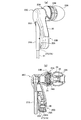
- FIG. 2 is an explanatory diagram showing the earphone structure of the sound processing device according to the embodiment of the present invention.
- FIG. 2A is an explanatory view showing the external structure
- FIG. 2B is a cross-sectional view showing the internal structure.
- the housing 20 includes a first housing portion 20A for housing the speaker unit 24 and a second housing portion 20B for housing the microphone 26.
- 20 A of 1st accommodating parts are provided with the acoustic radiation
- the second accommodating portion 20B includes an internal space 20B1 on the acoustic passive surface 26A side of the microphone 26. The internal space 20B1 of the second accommodating portion 20B communicates with the outside through the microphone hole portion 27.
- the earphone 2 includes a sound conduit 28 disposed on the acoustic radiation hole 25 side of the housing 20.
- the sound conduit 28 extends along the axis (central axis) of the acoustic radiation hole 25.
- An auricle connection portion 23 ⁇ / b> A is attached to the sound conduit 28.
- the auricle connection portion 23 ⁇ / b> A is provided around the sound conduit 28.
- an auricle contact portion 23B is provided on the side surface of the housing on the auricle connection portion 23A side.
- the speaker unit 24 has a known configuration, and includes a vibration unit having a voice coil and a diaphragm and a magnetic circuit.
- the diaphragm has an acoustic radiation surface 24A.
- an armature type (electromagnetic type) speaker unit may be adopted.
- the housing 20 includes a bent portion 20C that is bent from the first storage portion 20A toward the second storage portion 20B.
- the first accommodating portion 20 ⁇ / b> A extends along the axis (center axis) of the acoustic radiation hole portion 25.
- the second accommodating portion 20B extends from the bent portion 20C in a direction different from that of the first accommodating portion 20A.
- the extending direction of the first accommodating portion 20A and the extending direction of the second accommodating portion 20B intersect each other.
- the cord 21 is drawn out from a cord drawing hole 20D provided in the housing 20.
- the cord 21 is drawn from the housing 20 via the cord holding portion 21 ⁇ / b> A of the housing 20.
- a part of the cord holding portion 21A on one end side is supported inside the housing 20, and a part of the cord holding portion 21A on the other end side is a cord drawing hole. Projecting from the portion 20 ⁇ / b> D toward the outside of the housing 20.
- the second accommodating portion 20B extends from the bent portion 20C toward the cord holding portion 21A. Moreover, the 2nd accommodating part 20B is extended along the protrusion direction of 21 A of cord holding parts. The second accommodating portion 20B extends along the cord holding portion 21A.
- the second accommodating portion 20 ⁇ / b> B includes a microphone hole portion 27.
- the cord holding portion 21A is disposed at a position facing the microphone hole portion 27 of the second housing portion 20B.
- the cord holding portion 21 ⁇ / b> A is disposed so as to face the opening 27 of the microphone hole portion 27.
- the cord holding portion 21 ⁇ / b> A has a large bending rigidity with respect to the cord 21.
- a gap 20 ⁇ / b> S is provided between the side surface of the cord holding portion 21 ⁇ / b> A and the microphone hole portion 27.
- a gap 20 ⁇ / b> S is provided between the side surface of the cord holding portion 21 ⁇ / b> A and the microphone hole portion 27.
- the cord holding portion 21A extends in a straight line
- the second storage portion 20B extends in a curved shape.
- a gap 20S is formed between the cord holding portion 21A and the side surface of the second accommodating portion 20B.
- the cord 21 is disposed in the housing 20.
- the cord 21 is disposed on the side opposite to the acoustic radiation hole 25 side of the housing 20.
- the axis (center axis) of the acoustic passive surface 26 ⁇ / b> A of the microphone 26 intersects with the axis (center axis) of the acoustic radiation hole 25.
- the microphone hole 27 opens toward the cord 21 or the cord holding portion 21A.
- the cord holding portion 21A is disposed at a position facing the microphone hole portion 27, so that the user's hand or clothing contacts the microphone hole portion 27. And the microphone 26 can be prevented from picking up a contact sound that is unpleasant for the user.
- the earphone 2 when the telephone handset (or the main body of the mobile phone) is brought close to the housing 20 and the sound emitted from the handset is processed (including amplification or attenuation) and is desired to be listened to, the earphone 2 includes the cord holding portion 21A.
- the handset can be prevented from coming into contact with the microphone hole portion 27. Since the contact between the handset and the microphone hole 27 is suppressed, the contact sound when the handset touches the microphone hole 27 is processed (including amplification or attenuation) and emitted from the speaker unit 24 of the earphone 2. Can be suppressed.
- the contact between the handset and the microphone hole 27 is suppressed, it is possible to suppress the discomfort experienced by the user due to the processed contact sound (including amplification or attenuation). In addition, it is difficult to hear the sound emitted from the speaker unit of the handset due to the contact sound caused by the contact between the handset and the microphone hole 27, and it is possible to avoid the problem of overlooking important requirements.
- One end portion (end portion on the housing 20 side) of the cord holding portion 21A is supported by the housing 20.
- the cord holding portion 21A itself has bending rigidity.
- a gap 20 ⁇ / b> S is provided between the cord holding portion 21 ⁇ / b> A and the housing 20. For this reason, even if the cord holding portion 21A is pushed by a receiver or the like, it is possible to avoid the cord holding portion 21A itself or the cord 21 from contacting the microphone hole portion 27.
- the axis of the acoustic passive surface 26A of the microphone 26 housed in the housing 20 of the earphone 2 intersects the axis of the acoustic radiation surface of the speaker unit 24. ing.
- the axis of the acoustic passive surface 26 ⁇ / b> A of the microphone 26 intersects the axis of the acoustic radiation hole portion 25 along the axis of the acoustic radiation surface of the speaker unit 24.
- intersecting means that the axis of the target acoustic passive surface 26A and the axis of the acoustic radiation surface intersect in a three-dimensional space, and one of the axis of the target acoustic passive surface 26A and the axis of the acoustic radiation surface. This also includes intersecting when the other axis is projected into a two-dimensional plane including the other axis.
- the microphone hole portion 27 provided in the housing 20 opens toward the cord 21 or the cord holding portion 21A. For this reason, it is possible to suppress the occurrence of howling (oscillation phenomenon) caused by the vibration generated by driving the speaker unit 24 being propagated to the microphone 26 via the housing 20.
- the microphone hole portion 27 opens toward the cord 21 or the cord holding portion 21A. For this reason, the sound generation direction of the telephone handset can be directed directly toward the microphone hole 27. Further, the sound emitted from the handset can be reliably collected by the microphone 26. Since the sound wave entering the microphone hole 27 passes through the internal space 20B1 and vibrates the acoustic passive surface 26A, the microphone 26 can collect sound.
- the housing 20 of the earphone 2 includes a first housing portion 20A in which the speaker unit 24 is housed and a second housing portion 20B in which the microphone 26 is housed.
- the first accommodating portion 20A and the second accommodating portion 20B extend in different directions. For this reason, the speaker unit 24 and the microphone 26 can be separated. By providing a predetermined distance between the speaker unit 24 and the microphone 26, the above-described howling can be avoided.
- the second accommodating portion 20 ⁇ / b> B extends along the cord 21. For this reason, when the user wears the earphone 2, the position of the microphone 26 is arranged below the user's ear.
- a conversation is made using a mobile phone (for example, a smart phone type mobile phone)
- the user's voice is collected by the microphone of the earphone, so that the user can hear the volume of the voice and the mobile phone.
- the user can utter an appropriate amount of voice.
- FIG. 3 is an explanatory diagram showing a circuit configuration of the sound processing apparatus according to the embodiment of the present invention.
- the main body 3 includes an audio signal processing circuit 30 that processes (including amplification or attenuation) the audio signal collected by the microphone 26 and outputs the processed signal to the speaker unit 24.
- the audio signal processing circuit 30 includes an audio signal input unit 31 and an audio signal output unit 37. By connecting the connection terminal unit 22 of the earphone 2 to the connected terminal unit 4E of the main body 3, a signal line from the microphone 26 is obtained.
- the audio signal sent to the microphone terminal 22M via the 21M is input to the audio signal input unit 31, and the processed (including amplified or attenuated) audio signal output from the audio signal output unit 37 is input to the speaker terminal 22S and the signal. It is sent to the speaker unit 24 via the line 21S.
- the audio signal processing circuit 30 is, for example, a preamplifier (preamplifier) 32 that processes (including amplification or attenuation) an audio signal output from the audio signal input unit 31, a switching circuit 33, a bandpass filter 34, and a volume adjustment. Unit (slide volume) 35, power amplifier 36, and audio signal output unit 37.
- a power supply circuit 38 for supplying a drive voltage Vcc to the audio signal processing circuit 30 is provided.
- a battery (battery) 38A is connected to the power supply circuit 38, and a power cut-off unit 38B is provided between the battery (battery) 38A and the power supply circuit 38.
- the audio signal processing circuit 30 is operated by an operation signal from the operation unit 40.
- the operation unit 40 outputs operation signals obtained by the mode change switch 41, the volume adjustment wheel 42, the power switch 43, and the sound pressure balance adjustment operation unit 46 described above.
- the audio signal processing circuit 30 may not include the power supply circuit 38 but the main body 3 may include the power supply circuit 38.
- the operation unit 40 sends a switching operation signal from the mode change switch 41 to the switching circuit 33, sends an adjustment operation signal from the volume adjustment wheel 42 to the volume adjustment unit 35, and sends an on / off operation signal from the power switch 43 to the power cutoff unit. Send to 38B. Also, an adjustment signal from the sound pressure balance adjustment operation unit 46 is sent to the sound pressure balance adjustment unit 39.
- the sound pressure balance adjusting unit 39 is connected to the right ear speaker unit 24 (R) and the right ear speaker unit 24 (L) of the attached earphone 2A. It has a function to adjust the sound pressure balance.
- the control means (for example, the microcomputer) 50 can determine which of the earphone 2 or the attached earphone 2A is connected to the main body 3 as described later. When it is detected that the earphone 2 is connected to the main body 3, the control unit sends a signal to the sound pressure balance adjustment unit 39 to turn off (stop) the adjustment function of the sound pressure balance adjustment unit 39.
- the switching circuit 33 selectively switches between a plurality of different band pass filters 34 (34A to 34D) according to a switching operation signal input by the mode switching switch 41.
- the volume adjustment unit 35 variably controls the volume of the audio signal according to the adjustment signal input by the volume adjustment wheel 42.
- the power cut-off unit 38B connects / cuts off the battery 38A and the power supply circuit 38 by an on / off operation signal input by the power switch 43.
- the plurality of different bandpass filters 34 may be incorporated in the audio signal processing circuit 30 in a changeable state or in a state where any one or a plurality of selected ones are fixed.
- the fixed state is a state in which the characteristics of the band pass filter 34 corresponding to each mode incorporated in the audio signal processing circuit 30 cannot be changed after being incorporated in the audio signal processing circuit 30. Say something.
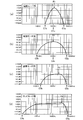
- FIG. 4 is an explanatory diagram showing a mode switching mode according to the use environment in the sound processing apparatus according to the embodiment of the present invention, and shows characteristics of a plurality of different bandpass filters corresponding to each mode. .
- the speech processing apparatus 1 according to the embodiment of the present invention can selectively switch an operation mode suitable for each use environment in response to a difference in use environment.
- the band-pass filter 34 of the audio signal processing circuit 30 includes a plurality of different band-pass filters 34A, 34B, 34C, and 34D, and is selectively selected by the switching circuit 33. Can be switched to.
- the plurality of different bandpass filters 34A, 34B, 34C, 34D can be set for, for example, a telephone mode, a conversation mode, a normal mode, and a television mode.
- the first bandpass filter 34A (for telephone mode), which is one of a plurality of different bandpass filters 34A to 34D, has, for example, the characteristics shown in FIG.
- the first band-pass filter 34A has a characteristic of selectively allowing the sound (within a frequency band from about 300 Hz to about 3400 Hz) emitted from a telephone handset to pass through the microphone hole 27 of the earphone 2. It is suitable for a usage environment in which the speaker unit is brought close to the user and the sound emitted from the receiver is processed (including amplification or attenuation).
- the first band-pass filter 34A includes a low-pass filter having a cutoff frequency C1a (in the case of illustration: about 2500 Hz) of about 2000 to about 3000 Hz, and a cutoff frequency C1b (in the case of illustration: about 700 Hz) of about 300 to about 800 Hz. And an equalizer having a center frequency C1c (in the illustrated case: about 1000 Hz) of about 700 Hz to about 1200 Hz.
- the first band pass filter 34A has a filter characteristic that the cut-off frequencies C1a to C1b are relatively narrow.
- the frequency P1 at which the amplification factor is maximum is between about 1000 Hz and about 2000 Hz.
- the first bandpass filter 34A When switching to the first bandpass filter 34A having such filter characteristics, it is possible to select and process (including amplification or attenuation) the voice emitted from the telephone handset. In addition, since sounds such as environmental sounds other than the frequency band selected by the first band pass filter 34A are not processed (including amplification or attenuation), sound generated from the handset even if noise is generated around the user Can be heard clearly. In addition, the frequency band of the sound emitted from the telephone handset is 300 Hz to 3400 Hz.
- the second band-pass filter 34B (for conversation mode), which is one of a plurality of different band-pass filters 34A to 34D, has, for example, the characteristics shown in FIG.
- the second band-pass filter 34B is a low-pass filter having a cutoff frequency C2a (in the case of illustration: about 4900 Hz) higher than the cut-off frequency C1a (in the case of illustration: about 2500 Hz) in the low-pass filter of the first bandpass filter 34A.
- the frequency P2 at which the amplification factor is maximum is between about 900 Hz and about 2000 Hz (about 1000 Hz in the illustrated example).
- the maximum amplification factor of the second bandpass filter 34B has characteristics smaller than the maximum amplification factor of the first bandpass filter 34A.
- the second bandpass filter 34B By switching to the second bandpass filter 34B having such characteristics, it is possible to effectively process (including amplification or attenuation) the conversational voice in an environment where conversation is mainly used.
- the conversational voice when used in a conference room or the like, the conversational voice is effectively processed (including amplification or attenuation), and other noises other than the band selected by the second bandpass filter 34B are processed (amplified).
- the conversation voice can be heard clearly even if there is noise in the surroundings.
- the second band pass filter has a lowest frequency (the lowest frequency at the smallest gain) smaller than the lowest frequency of the third band pass filter described later, and is relatively less than the third band pass filter. It has a characteristic of allowing sound in a small frequency band to pass.
- the third bandpass filter 34C (for the normal mode), which is one of a plurality of different bandpass filters 34A to 34D, has, for example, the characteristics shown in FIG.
- the third band-pass filter 34C is a low-pass filter having a cutoff frequency C3a (in the case of illustration: about 4400 Hz) smaller than the cut-off frequency C2a (in the case of illustration: about 4900 Hz) in the low-pass filter of the second bandpass filter 34B.
- a high-pass filter having a cutoff frequency C3b (in the case of illustration: about 300 Hz) higher than the cut-off frequency C2b (in the case of illustration: about 150 Hz) in the high-pass filter of the second bandpass filter 34B.
- the frequency P3 at which the amplification factor is maximum is between about 2000 Hz and about 3000 Hz.
- the maximum amplification factor of the third bandpass filter 34C has characteristics smaller than the maximum amplification factor of the second bandpass filter 34B.
- the fourth band pass filter 34D (for television mode), which is one of a plurality of different band pass filters 34A to 34D, has, for example, the characteristics shown in FIG.
- the fourth band-pass filter 34D is a low-pass filter having a cutoff frequency C4a (in the case of illustration: about 5300 Hz) higher than the cut-off frequency C3a (in the case of illustration: about 4400 Hz) in the low-pass filter of the third band-pass filter 34C.
- a high-pass filter having a cutoff frequency C4b (in the case of illustration: about 49 Hz) smaller than the cut-off frequency C3b (in the case of illustration: about 300 Hz) in the high-pass filter of the third bandpass filter 34C.
- the frequency P4 at which the amplification factor is maximum is between about 3000 Hz and about 4000 Hz.
- the maximum gain of the fourth bandpass filter 34D is smaller than the maximum gain of the third bandpass filter 34C.
- the mode switched to the fourth bandpass filter 34D is suitable for viewing the television. Further, by adjusting the cut-off frequencies C3b to C3a from about 50 Hz to about 15 kHz which is the frequency range of music, it is suitable for listening to music.
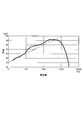
- 5 to 9 show the output sound pressure frequency characteristics of the speaker unit in the sound processing apparatus according to the embodiment of the present invention.
- the output sound pressure frequency characteristics of the speaker unit when the first to fourth band-pass filters are employed are indicated by curves, and (10000 Hz, 100 dB) and (10 Hz, 40 dB).
- a reference line connecting the points is indicated by a dashed line.
- a range in which the sound pressure is higher than the reference line is defined as a convex undulation, and is surrounded by a broken line in the figure.
- the characteristics of the output sound pressure frequency characteristics when each band pass filter is adopted depending on the size of this undulation are shown.
- the output sound pressure frequency characteristics of the speaker unit have the aforementioned undulations changed by the first to fourth band-pass filters.
- FIG. 5 shows the output sound pressure frequency characteristics when the mode corresponding to the first bandpass filter is selected.
- the sound pressure gradually increases from about 20 Hz to about 130 Hz.
- the output sound pressure frequency characteristics are flat.
- the sound pressure gradually increases from about 300 Hz, and has a peak in the frequency band of about 1600 Hz to about 2000 Hz.
- the sound pressure decreases toward about 20000 Hz.
- convex undulations are observed in a frequency band between about 50 Hz and about 800 Hz. It can be seen that the convex undulations are smaller than those shown in FIGS.
- FIG. 6 shows the output sound pressure frequency characteristics when the mode corresponding to the second bandpass filter is selected.
- the sound pressure gradually increases from about 20 Hz to about 1600 Hz.
- the output sound pressure frequency characteristics are crested.
- the output sound pressure frequency characteristic is flat.
- the sound pressure gradually decreases.
- convex undulations are observed in a frequency band between about 50 Hz and about 800 Hz. It can be seen that this convex undulation is larger than those shown in FIGS.
- FIG. 7 shows the output sound pressure frequency characteristics when the mode corresponding to the third bandpass filter is selected.
- the sound pressure gradually increases from about 20 Hz to about 4000 Hz.
- the mountain-like portion seen in the frequency band of about 130 Hz to about 300 Hz is not seen in FIG.
- the frequency band from about 4000 Hz to about 20000 Hz the sound pressure gradually decreases.
- convex undulations are observed in a frequency band between about 50 Hz and about 800 Hz. It can be seen that the convex undulations are smaller than those shown in FIGS.
- FIG. 8 shows the output sound pressure frequency characteristics when the mode corresponding to the fourth bandpass filter is selected.
- the sound pressure gradually increases from about 20 Hz to about 63 Hz.
- the rate of increase in sound pressure increases rapidly in the frequency band from about 63 Hz to about 125 Hz.
- the output sound pressure frequency characteristic is flat.
- the sound pressure gradually increases from about 1000 Hz to about 4000 Hz.
- the frequency band from about 4000 Hz to about 20000 Hz the sound pressure gradually decreases.
- convex undulations are observed in a frequency band between about 50 Hz and about 800 Hz. It can be seen that the convex undulations are larger than those in FIGS.
- FIG. 9 shows a schematic diagram of output sound pressure frequency characteristics corresponding to each mode described above.
- the line B1 shown in the figure is the output sound pressure frequency characteristic when the first band pass filter is selected.
- the main frequency of the sound is obtained. It can be seen that the processed sound is output from the speaker unit around a certain frequency of about 1000 Hz. It is possible to grasp whether the amplification factor is applied to a human voice, a television sound, or a music sound by the size of the convex undulations.
- the line B2 shown in the figure is the output sound pressure frequency characteristic when the second bandpass filter is selected.
- a mode corresponding to the second bandpass filter from this line B2 a lower frequency band is obtained. It can be seen that the sound generated at is output from the speaker unit, and the sound emitted at the conference or the like can be heard more clearly.
- the line B3 shown in the figure is the output sound pressure frequency characteristic when the third bandpass filter is selected. By selecting a mode corresponding to the third bandpass filter from this line B3, normal life or the like can be obtained. It can be seen that the necessary voice can be effectively heard in the usage environment.
- the line B4 shown in the figure is the output sound pressure frequency characteristic when the fourth bandpass filter is selected.
- the second bandpass filter is selected. It can be seen that a lower frequency sound can be heard than when the mode corresponding to the filter is selected. Therefore, since it corresponds to the sound of the television (about 5 Hz to about 20 kHz) and the frequency range of the music (about 50 Hz to about 15 kHz), it is possible to enjoy television and music.
- Switching between a plurality of different bandpass filters 34A to 34D can be performed by operating the mode switch 41 as described above.
- the operation unit 40 outputs, for example, an operation signal for sequentially switching a plurality of different bandpass filters 34A to 34D each time the mode switch 41 is pressed.
- the main body 3 includes a switching display unit 45 as shown in FIG. 3 as an example.
- the switching display unit 45 outputs a display signal so that the first light source 4C exhibits a different emission color corresponding to each of a plurality of different bandpass filters 34A to 34D switched by the mode switching switch 41. According to this, the user can visually recognize which mode of use environment is currently set by looking at the emission color of the first light source 4C provided in the housing 4 of the main body 3.
- the mode switching switch 41 has a normal switching operation for sequentially switching a plurality of different bandpass filters 34A, 34B, 34C, 34D. For example, when the mode changeover switch 41 is pressed, if the currently set bandpass filter 34 is the first bandpass filter 34A, the second bandpass filter 34B, the third bandpass filter 34C, and the fourth bandpass filter 34D. Switch to one of them.
- a plurality of different bandpass filters 34A, 34B, 34C, and 34D may be switched in this order, or may be changed in order of switching such as the bandpass filters 34B, 34A, 34C, and 34D. .
- the mode changeover switch 41 has a specific changeover operation for directly switching from one of the second bandpass filter 34B, the third bandpass filter 34C, and the fourth bandpass filter 34D to the first bandpass filter 34A. Yes. For example, when the mode changeover switch 41 is continuously pressed or long pressed, the currently set bandpass filter 34 is selected from the second bandpass filter 34B, the third bandpass filter 34C, and the fourth bandpass filter 34D. Is switched to the first bandpass filter 34A. According to this, it is possible to switch to the mode of the telephone usage environment (telephone mode; mode corresponding to the first band pass filter) by one operation or a series of operations, and so on, when a call is suddenly made.
- mode of the telephone usage environment telephone mode; mode corresponding to the first band pass filter
- a sensor such as an infrared sensor can be provided on the earphone 2 so that the sensor senses that the telephone handset has approached the earphone 2 and can be switched to the telephone usage environment mode. In this case, since the mode is switched without the user pressing the switching button, usability is improved for the user.
- the main body 3 includes a switching notification unit 44 related to the operation of the mode switching switch 41.
- the switching notification unit 44 notifies the user that the volume of the audio signal output to the speaker unit 24 is increased or decreased by switching the mode switching switch 41.
- the switching notification unit 44 performs processing (including amplification or attenuation) in the audio signal processing circuit 30 and outputs the audio to the speaker unit 24 during the switching period of the bandpass filter 34 by the changeover switch 41. Temporarily shut off the signal.
- the main body 3 causes the speaker unit 24 to output a notification sound. According to this, when switching the mode according to the use environment, the user can know in advance that the volume output from the speaker unit 24 is increased or decreased. In particular, it is possible to avoid feeling uncomfortable due to sudden volume increase.
- FIG. 10 is an explanatory diagram showing configurations of the connection terminal portion of the earphone and the connected terminal portion of the main body.
- FIG. 10A shows a state in which the earphone 2 (first earphone) is connected to the main body 3
- FIG. 10B shows a state in which the attached earphone (second earphone) 2 ⁇ / b> A is connected to the main body 3. Is shown.
- the earphone 2 is one in which one speaker unit 24 and one microphone 26 are housed in a single housing 20, and the connection terminal portion 22 includes a microphone terminal 22M and a speaker terminal 22S.
- the connection terminal portion 22 includes non-connection terminals T1 and T2 that are not connected to the speaker unit or the microphone.
- the attached earphone 2A includes two housings 20 (a right ear housing 20R and a left ear housing 20L), each of which houses one speaker unit 24 and one microphone 26.
- the connection terminal portion 22A includes a right ear microphone terminal 22M (R), a speaker terminal 22S (R), a left ear microphone terminal 22M (L), and a speaker terminal 22S (L).
- the connected terminal portion 4E of the main body 3 includes speaker output terminals (speaker terminals) 4E1 and 4E2 and microphone input terminals (microphone terminals) 4E3 and 4E4.
- speaker output terminals speaker terminals
- microphone input terminals microphone terminals
- the other of the speaker output terminals 4E1 and 4E2 (speaker output terminal 4E1 in the illustrated example) is connected to the non-connection terminal T2, and the other of the microphone input terminals 4E3 and 4E4 (microphone input terminal 4E3 in the illustrated example) is not connected. Connected to terminal T1.
- connection terminal portion 22A of the attached earphone 2A When the connection terminal portion 22A of the attached earphone 2A is connected to the connected terminal portion 4E, the microphone terminals 22M (R) and 22M (L) of the connection terminal portion 22A are respectively connected to the microphone input terminals (covered) of the connected terminal portion 4E.
- Microphone terminals) 4E3 and 4E4 and the speaker terminals 22S (R) and 22S (L) of the connection terminal portion 22A are connected to speaker output terminals (speaker terminals) 4E2 and 4E1 of the connected terminal portion 4E, respectively.
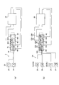
- FIG. 11 is an explanatory diagram showing a specific configuration example of the connection terminal portion in the earphone and the attached earphone.
- FIG. 11A shows a specific configuration example of the connection terminal portion 22 of the earphone 2
- FIG. 11B shows a specific configuration example of the connection terminal portion 22A of the attached earphone 2A.
- the connection terminal portion 22 of the earphone 2 and the connection terminal portion 22A of the attached earphone 2A have a pin shape, and both have substantially the same form in terms of external dimensions such as the terminal diameter. Each of them can be connected to the connected terminal portion 4E of the main body 3.
- the connection terminal portion 22A of the attached earphone 2A has six terminals including speaker terminals 22S (R) and 22S (L), microphone terminals 22M (R) and 22M (L), a speaker ground terminal 22G1 as a ground, and a microphone ground terminal 22G2.
- speaker terminals 22S (R) and 22S (L) on the distal end side of the connection terminal portion 22A are electrically connected to the speaker terminals 22S (R) -1 and 22S (L) -1 on the cord 21 side, respectively. ing.
- the microphone terminals 22M (R) and 22M (L) on the distal end side of the connection terminal portion 22A are electrically connected to the microphone terminals 22M (R) -1 and 22M (L) -1 on the cord 21 side, respectively. Has been.
- connection terminal portion 22 of the earphone 2 has a similar terminal structure, and includes a speaker terminal 22S corresponding to one speaker unit, a microphone terminal 22M corresponding to one microphone, one speaker unit, and Two terminals (non-connection terminals T1, T2) that are in a non-connection state with one microphone are provided.
- the non-connection terminals T1 and T2 correspond to the microphone terminal 22M (L) and the speaker terminal 22S (L) in the connection terminal portion 22A of the attached earphone 2A.
- the non-connection terminals T1 and T2 include a speaker unit and a microphone. Connection to is not made.
- connection terminal portion 22 has a speaker ground terminal 22G1 and a microphone ground terminal 22G2 similarly to the connection terminal portion 22A.
- the speaker terminal 22S on the distal end side of the connection terminal portion 22 is electrically connected to the speaker terminal 22S-1 on the cord 21 side, and the microphone terminal 22M on the distal end side is connected to the microphone terminal 22M-1 on the cord 21 side. And are electrically connected.
- the unconnected terminal T1-1 on the cord side is electrically connected to the microphone ground terminal 22G2-1 on the cord side via a wiring (conductive wire or the like) Sp.
- the non-connecting terminal T1 and the microphone ground terminal 22G2 are electrically connected, and the non-connecting terminal T1 is short-circuited (grounded).
- the non-connection terminal T1 is short-circuited, but the non-connection terminal T2 may be short-circuited.
- the control means (eg, microcomputer) 50 of the main body 3 detects that the earphone 2 is connected to the main body 3 by detecting this short circuit. At that time, the control unit 50 controls the sound pressure balance adjustment unit 39 that adjusts the sound pressure balance of the audio signals output to the left and right speaker output terminals 4E1 and 4E2, and turns off (stops) the sound pressure balance adjustment function. .
- the control unit 50 controls the sound pressure balance adjustment unit 39 that adjusts the sound pressure balance of the audio signals output to the left and right speaker output terminals 4E1 and 4E2, and turns off (stops) the sound pressure balance adjustment function.
- FIG. 12 is an explanatory diagram showing the main body of the speech processing apparatus according to the embodiment of the present invention.
- FIG. 12A shows the rear configuration of the main body
- FIG. 12B shows the battery insertion portion of the main body.
- a holding clip 4F for holding the main body 3 on a user's clothes or the like is provided on the back side of the main body 3.
- the main body 3 includes a battery insertion portion 4H into which a battery or a rechargeable battery can be inserted.
- the battery insertion portion 4H is covered with a lid portion 4G.
- the lid 4G is opened, as shown in FIG. 12 (b), the battery 38A, +-terminals 38A1 and 38A2 that are in electrical contact with the battery 38A, and the user can manually adjust, for example.
- a sound pressure balance adjustment operation unit 46 having a wheel shape at a position is provided.
- the sound pressure balance adjustment operation unit 46 sends an adjustment signal to the sound pressure balance adjustment unit 39 to balance the output sound pressures of one speaker unit and the other speaker unit of the two speaker units included in the earphone 2A. To be adjusted. By adjusting the sound pressure balance adjustment operation unit 46, it is possible to increase the sound output from one speaker unit and reduce the sound output from the other speaker unit. Then, by adjusting the sound pressure balance adjustment operation unit 46 to the maximum of one speaker unit, it is possible to output sound only from one of the two speaker units. Specifically, according to the adjustment state of the sound pressure balance adjustment operation unit 46, for example, by changing the value of the variable resistance of the sound pressure balance adjustment unit 39, the sound output from one and the other speaker units Adjust to small or large. In the above description, the example in which the sound pressure balance adjustment in the sound pressure balance adjustment unit 39 is performed by adjusting the value of the variable resistor is shown. Instead, digital signal processing is performed using a DSP (digital signal processor). May adjust the sound pressure balance.
- DSP digital signal processor
- the sound pressure balance adjustment unit 39 turns on (operates) or turns off (stops) the balance adjustment function according to the adjustment signal from the control means 50. That is, the main body 3 can stop the adjustment by the sound pressure balance adjustment operation unit 46 for the audio signal output from the audio signal processing circuit 30 to the speaker unit of the first earphone (earphone 2). This operation will be described in detail below.
- the sound pressure balance adjustment unit 39 included in the main body 3 is for the right ear so as to correspond to the attached earphone 2A including the housing 20R attached to the user's right ear and the housing 20L attached to the left ear.
- the right ear adjustment circuit that adjusts the sound signal collected by the microphone of the housing 20R and outputs it to the speaker unit of the housing 20R, and the sound signal collected by the microphone of the left ear housing 20L adjusts the housing 20L.
- Left ear adjustment circuit for outputting to the speaker unit.
- the audio balance adjustment unit 39 includes the right ear adjustment circuit and the left ear adjustment circuit described above. For example, it is designed so that an audio signal collected by the microphone of the earphone 2 is input only to the right ear adjustment circuit.
- a user who uses the attached earphone 2A connected to the main body 3 operates the sound pressure balance adjustment operation unit 46 so that sound is output only from the left ear speaker unit ( It may be considered that the sound is adjusted so that no sound is output from the right-ear speaker unit.
- the earphone 2 in which one speaker unit and one microphone are housed in one housing is connected to the main body 3, an audio signal is input only to the right ear adjustment circuit. If the sound pressure balance adjustment unit 39 is functioning at this time, the right ear adjustment circuit does not output, so that no sound can be heard from the speaker unit of the earphone 2, and the user misunderstands that there is a malfunction of the main body. there is a possibility.
- the control unit 50 detects that the earphone 2 in which one speaker unit and one microphone are housed in one housing is connected to the main body 3. Then, an adjustment signal is sent to the sound pressure balance adjustment unit 39, and the adjustment function of the sound pressure balance adjustment unit 39 is turned off (stopped).
- the sound pressure balance adjustment operation unit 46 is operated in any manner. Even if it is done, an audio signal is always output to the speaker unit of the earphone 2. Thereby, when the earphone 2 is connected to the main body 3, the problem that the sound is not output from the speaker unit can be solved.
- the control unit 50 detects that the earphone 2 in which one speaker unit and one microphone are housed in one housing is connected to the main body 3.
- the sound pressure balance adjustment unit 39 By sending a signal to the sound pressure balance adjustment unit 39 and turning off (stopping) the adjustment function of the sound pressure balance adjustment unit 39, the problem that the sound is not output from the speaker unit when the earphone 2 is connected to the main body 3 is solved. did.
- the sound processing device 1 is configured to detect that the earphone 2A is connected to the main body 3, and the control means 50 detects that the earphone 2A is connected to the main body 3, the sound pressure balance adjustment is performed.
- a signal is sent to the unit 39 to turn on (operate) the adjustment function of the sound pressure balance adjustment unit 39.
- the sound pressure balance adjustment function when the earphone 2A is connected to the main body 3 is restored.
- the audio signal is output to the speaker unit without adjusting the sound pressure.
- the processing steps for the method of bypassing the signal path of the audio signal with respect to the sound pressure balance adjusting unit 39 and the digital processing of the audio signal performed by the sound pressure balance adjusting unit 39 are described.
- a method of skipping the image can be considered, but any specific method may be used.
- connection terminal portion 22A of the attached earphone 2A including the two housings 20 When the connection terminal portion 22A of the attached earphone 2A including the two housings 20 is connected to the connected terminal portion 4E, the microphone terminals 22M (R) and 22M (L) of the connection terminal portion 22A are connected terminal portions, respectively.
- the speaker terminals 22S (R) and 22S (L) of the connection terminal portion 22A are connected to the speaker output terminals 4E2 and 4E1 of the connected terminal portion 4E, respectively.
- the audio signal output from the audio signal processing circuit 30 to the speaker output terminals 4E2 and 4E1 may be a monaural signal or a stereo signal.
- an audio signal obtained by processing (including amplification or attenuation) the audio signal input to the microphone terminal 22M (R) is output to the speaker output terminal 4E2 and input to the microphone terminal 22M (L).
- the audio signal processed (including amplified or attenuated) is output to the speaker output terminal 4E2.
Landscapes
- Engineering & Computer Science (AREA)
- Physics & Mathematics (AREA)
- Acoustics & Sound (AREA)
- Signal Processing (AREA)
- Health & Medical Sciences (AREA)
- General Health & Medical Sciences (AREA)
- Neurosurgery (AREA)
- Otolaryngology (AREA)
- Manufacturing & Machinery (AREA)
- Headphones And Earphones (AREA)
- Circuit For Audible Band Transducer (AREA)
Priority Applications (4)
| Application Number | Priority Date | Filing Date | Title |
|---|---|---|---|
| JP2012555984A JP5209828B1 (ja) | 2012-02-01 | 2012-02-01 | イヤホン |
| EP12867398.5A EP2811755B1 (fr) | 2012-02-01 | 2012-02-01 | Dispositif de traitement audio |
| US14/375,993 US20150016625A1 (en) | 2012-02-01 | 2012-02-01 | Audio processing device |
| PCT/JP2012/052323 WO2013114597A1 (fr) | 2012-02-01 | 2012-02-01 | Dispositif de traitement audio |
Applications Claiming Priority (1)
| Application Number | Priority Date | Filing Date | Title |
|---|---|---|---|
| PCT/JP2012/052323 WO2013114597A1 (fr) | 2012-02-01 | 2012-02-01 | Dispositif de traitement audio |
Publications (1)
| Publication Number | Publication Date |
|---|---|
| WO2013114597A1 true WO2013114597A1 (fr) | 2013-08-08 |
Family
ID=48713135
Family Applications (1)
| Application Number | Title | Priority Date | Filing Date |
|---|---|---|---|
| PCT/JP2012/052323 Ceased WO2013114597A1 (fr) | 2012-02-01 | 2012-02-01 | Dispositif de traitement audio |
Country Status (4)
| Country | Link |
|---|---|
| US (1) | US20150016625A1 (fr) |
| EP (1) | EP2811755B1 (fr) |
| JP (1) | JP5209828B1 (fr) |
| WO (1) | WO2013114597A1 (fr) |
Cited By (2)
| Publication number | Priority date | Publication date | Assignee | Title |
|---|---|---|---|---|
| CN104581481A (zh) * | 2014-12-19 | 2015-04-29 | 苏州锦腾电子科技有限公司 | 耳机耳塞 |
| JP2019021478A (ja) * | 2017-07-14 | 2019-02-07 | ヤマハ株式会社 | ケーブルブッシュ、イヤフォンハウジング、およびイヤフォン |
Families Citing this family (3)
| Publication number | Priority date | Publication date | Assignee | Title |
|---|---|---|---|---|
| EP3285886A1 (fr) * | 2015-04-23 | 2018-02-28 | The Procter and Gamble Company | Composition de soin capillaire |
| CN107046657A (zh) * | 2017-04-05 | 2017-08-15 | 重庆工业职业技术学院 | 一种多媒体教学非连接式手机音频放大装置及其使用方法 |
| CN112188376B (zh) * | 2018-06-11 | 2021-11-02 | 厦门新声科技有限公司 | 双耳助听器平衡调节的方法、装置及计算机可读存储介质 |
Citations (4)
| Publication number | Priority date | Publication date | Assignee | Title |
|---|---|---|---|---|
| JPS5843099U (ja) * | 1981-09-14 | 1983-03-23 | リオン株式会社 | 補聴器 |
| JPH0461996U (fr) | 1990-10-03 | 1992-05-27 | ||
| JP2002369295A (ja) * | 2001-06-07 | 2002-12-20 | Eiken Kk | 集音器とイヤホン用カバー |
| JP2005286500A (ja) * | 2004-03-29 | 2005-10-13 | Yashima Denki Kk | 補聴器用マイク付きイヤホン |
Family Cites Families (6)
| Publication number | Priority date | Publication date | Assignee | Title |
|---|---|---|---|---|
| DE69327396T2 (de) * | 1993-07-28 | 2000-05-11 | Pan Communications, Inc. | Zweiweg-Kommunikations-Ohrhörer |
| US6472935B2 (en) * | 1998-03-26 | 2002-10-29 | Maxim Integrated Products, Inc. | Combining networks for switchable path power amplifiers |
| US6374126B1 (en) * | 1999-11-10 | 2002-04-16 | Ericsson Inc. | Hands-free headset with stowable stereo earpiece |
| JP4310893B2 (ja) * | 2000-06-26 | 2009-08-12 | パナソニック株式会社 | コード巻き取り装置付きヘッドホン |
| JP3898134B2 (ja) * | 2003-01-22 | 2007-03-28 | Necトーキン株式会社 | 耳装着型の音情報伝達器 |
| US20100195860A1 (en) * | 2009-02-05 | 2010-08-05 | Cher Becker | Soft shell in-ear earphones with miniature speaker inserts |
-
2012
- 2012-02-01 EP EP12867398.5A patent/EP2811755B1/fr not_active Not-in-force
- 2012-02-01 US US14/375,993 patent/US20150016625A1/en not_active Abandoned
- 2012-02-01 WO PCT/JP2012/052323 patent/WO2013114597A1/fr not_active Ceased
- 2012-02-01 JP JP2012555984A patent/JP5209828B1/ja not_active Expired - Fee Related
Patent Citations (4)
| Publication number | Priority date | Publication date | Assignee | Title |
|---|---|---|---|---|
| JPS5843099U (ja) * | 1981-09-14 | 1983-03-23 | リオン株式会社 | 補聴器 |
| JPH0461996U (fr) | 1990-10-03 | 1992-05-27 | ||
| JP2002369295A (ja) * | 2001-06-07 | 2002-12-20 | Eiken Kk | 集音器とイヤホン用カバー |
| JP2005286500A (ja) * | 2004-03-29 | 2005-10-13 | Yashima Denki Kk | 補聴器用マイク付きイヤホン |
Cited By (2)
| Publication number | Priority date | Publication date | Assignee | Title |
|---|---|---|---|---|
| CN104581481A (zh) * | 2014-12-19 | 2015-04-29 | 苏州锦腾电子科技有限公司 | 耳机耳塞 |
| JP2019021478A (ja) * | 2017-07-14 | 2019-02-07 | ヤマハ株式会社 | ケーブルブッシュ、イヤフォンハウジング、およびイヤフォン |
Also Published As
| Publication number | Publication date |
|---|---|
| EP2811755B1 (fr) | 2018-07-04 |
| JP5209828B1 (ja) | 2013-06-12 |
| EP2811755A1 (fr) | 2014-12-10 |
| US20150016625A1 (en) | 2015-01-15 |
| EP2811755A4 (fr) | 2015-07-29 |
| JPWO2013114597A1 (ja) | 2015-05-11 |
Similar Documents
| Publication | Publication Date | Title |
|---|---|---|
| US9762991B2 (en) | Passive noise-cancellation of an in-ear headset module | |
| CN103125125B (zh) | 通信头戴耳机及将环境声转播到头戴耳机佩戴者的方法 | |
| CN110519671A (zh) | 无线耳机 | |
| US10748522B2 (en) | In-ear microphone with active noise control | |
| JP5209828B1 (ja) | イヤホン | |
| US20140211970A1 (en) | Earphone arrangements | |
| JP5825317B2 (ja) | 音声処理装置 | |
| TWI605721B (zh) | 耳道式耳機麥克風模組 | |
| CN213403429U (zh) | 一种耳机 | |
| JP2837641B2 (ja) | 耳かけ形補聴器 | |
| US10798501B2 (en) | Augmented hearing device | |
| JP3066305U (ja) | 聴力補助器 | |
| JP5942448B2 (ja) | 音声処理装置 | |
| CN111556401B (zh) | 声音降噪模组及耳机 | |
| JP5385472B2 (ja) | 音声処理装置 | |
| JP5703530B2 (ja) | 音声処理装置 | |
| TWM553910U (zh) | 具有微機電麥克風的耳道式耳機麥克風 | |
| CN115004717A (zh) | 具有更高抗风噪性能的无线耳麦 | |
| CN106101898B (zh) | 降噪耳机及其降噪方法 | |
| CN210745510U (zh) | 耳机 | |
| CN208337829U (zh) | 可切换内外麦克风的耳机 | |
| WO2023104261A1 (fr) | Dispositif de reproduction acoustique hybride à son directionnel non invasif |
Legal Events
| Date | Code | Title | Description |
|---|---|---|---|
| ENP | Entry into the national phase |
Ref document number: 2012555984 Country of ref document: JP Kind code of ref document: A |
|
| 121 | Ep: the epo has been informed by wipo that ep was designated in this application |
Ref document number: 12867398 Country of ref document: EP Kind code of ref document: A1 |
|
| WWE | Wipo information: entry into national phase |
Ref document number: 14375993 Country of ref document: US |
|
| NENP | Non-entry into the national phase |
Ref country code: DE |
|
| WWE | Wipo information: entry into national phase |
Ref document number: 2012867398 Country of ref document: EP |