WO2013114676A1 - サーモスタット装置 - Google Patents
サーモスタット装置 Download PDFInfo
- Publication number
- WO2013114676A1 WO2013114676A1 PCT/JP2012/075770 JP2012075770W WO2013114676A1 WO 2013114676 A1 WO2013114676 A1 WO 2013114676A1 JP 2012075770 W JP2012075770 W JP 2012075770W WO 2013114676 A1 WO2013114676 A1 WO 2013114676A1
- Authority
- WO
- WIPO (PCT)
- Prior art keywords
- passage
- thermostat
- cooling water
- valve
- thermostat device
- Prior art date
- Legal status (The legal status is an assumption and is not a legal conclusion. Google has not performed a legal analysis and makes no representation as to the accuracy of the status listed.)
- Ceased
Links
Images





Classifications
-
- F—MECHANICAL ENGINEERING; LIGHTING; HEATING; WEAPONS; BLASTING
- F01—MACHINES OR ENGINES IN GENERAL; ENGINE PLANTS IN GENERAL; STEAM ENGINES
- F01P—COOLING OF MACHINES OR ENGINES IN GENERAL; COOLING OF INTERNAL-COMBUSTION ENGINES
- F01P7/00—Controlling of coolant flow
- F01P7/14—Controlling of coolant flow the coolant being liquid
- F01P7/16—Controlling of coolant flow the coolant being liquid by thermostatic control
-
- G—PHYSICS
- G05—CONTROLLING; REGULATING
- G05D—SYSTEMS FOR CONTROLLING OR REGULATING NON-ELECTRIC VARIABLES
- G05D23/00—Control of temperature
- G05D23/01—Control of temperature without auxiliary power
- G05D23/13—Control of temperature without auxiliary power by varying the mixing ratio of two fluids having different temperatures
- G05D23/1306—Control of temperature without auxiliary power by varying the mixing ratio of two fluids having different temperatures for liquids
- G05D23/132—Control of temperature without auxiliary power by varying the mixing ratio of two fluids having different temperatures for liquids with temperature sensing element
- G05D23/1333—Control of temperature without auxiliary power by varying the mixing ratio of two fluids having different temperatures for liquids with temperature sensing element measuring the temperature of incoming fluid
Definitions
- the present invention relates to a thermostat device that is provided in a cooling water circuit of an automobile engine and appropriately controls the flow of cooling water according to the cooling water temperature.
- the thermostat device is mainly provided at an engine outlet and performs so-called engine outlet side control. About.
- thermostat devices For example, in a cooling water circuit of an automobile engine, the flow of cooling water is controlled according to the cooling water temperature. It is installed and arranged in an appropriate state on the cooling water outlet side or the cooling water inlet side.
- a bypass valve that opens and closes between the return passage leading to the engine inlet and the bypass passage is assembled to the end of the thermo element constituent member in the thermostat device.
- Patent Document 2 Japanese Patent Document 2
- the thermostat device of the type provided on the cooling water inlet side of the engine can achieve a certain degree of effect, but it can be used as it is as the type of thermostat device provided on the cooling water outlet side of the engine. Is impossible in terms of structure, and there is a need to take some measures.
- the coil spring for the bypass valve is fixed at the other end by the thermo element, so that the spring load urged by the bypass valve changes due to the thermo element's advance / retreat movement due to temperature. End up.
- the spring load becomes higher as the thermo element operates and moves to the side opposite to the main valve than the spring load when the thermo element is not operated, and as a result, the set pressure at which the bypass valve opens and closes changes.
- it is difficult to control to an appropriate constant pressure and it is desired to take measures that can eliminate these problems.
- the present invention has been made in view of such circumstances, and also adds a function as a bypass passage and a bypass valve to a thermostat valve that controls the flow of engine cooling water, and simplifies the overall configuration,
- the object is to obtain a thermostat device that can reduce the number of parts, improve the assemblability, and reduce the cost.
- a thermostat device in a cooling water circuit of an automobile engine, and the flow of cooling water between first and second passages is provided.
- a thermostat device comprising a main valve to be controlled and a thermo element that is disposed in the first passage and that drives and controls the main valve according to a coolant temperature, wherein the device body incorporating the thermostat device is a third body.
- a second valve body that includes a passage and opens and closes a communication hole that communicates the first passage and the third passage when a coolant pressure in the coolant circuit becomes a predetermined pressure or higher. It is characterized by being provided integrally with a device frame that holds the element.
- thermo element device is the thermo element device according to claim 1, wherein the second valve body is arranged so as to be movable coaxially with the device frame holding the thermo element, and a coil. By urging with a spring, the communication hole provided in a part of the device frame is closed regardless of the movement of the thermo element.
- the thermostat device according to the present invention (the invention described in claim 3) is the thermostat device according to claim 1 or 2, wherein the coil spring that biases the second valve body includes an end portion of the cylindrical portion of the device frame, a stopper, It is comprised so that it may be hold
- the thermostat device according to the present invention is the thermostat device according to any one of claims 1 to 3, wherein the device body communicates the first passage and the third passage.
- An opening is provided coaxially with the thermo-element, and a cylindrical portion of the device frame is fitted and held in the opening, and the device frame is pressed by a main spring that urges the main valve, thereby the device.
- the first passage and the third passage are separated from each other by being brought into contact with and locked to the body.
- the thermostat device according to the present invention is the thermostat device according to any one of claims 1 to 4, wherein the thermostat device drives and controls the first valve body constituting the main valve.
- An apparatus housing for supporting the thermo element, and the apparatus frame is fitted to the thermo element so that the thermo element is movably held, and a biasing force of the main spring is applied to a part of the apparatus housing.
- the device housing is assembled to the device body, whereby the device frame is released from the locked state and is urged toward the device body by the main spring. It is characterized by being assembled.
- the second valve body and the bypass passage opened and closed by the second valve body are integrally provided in the device frame.
- Body is not required to be configured separately from the thermostat valve, and can be integrated as a thermostat device, reducing the number of components and increasing the degree of freedom in the layout of the thermostat. It is also possible to achieve downsizing around the engine including the water system.
- the second valve body coaxially with the thermo-element, it is possible to integrally mold the apparatus frame and the communication hole (either resin or metal), and the second valve If the body is also made of metal, it can be press-molded, and if it is made of resin, it can be integrally molded, and since it has a simple structure, the parts that make up this second valve can be easily manufactured, which increases productivity And the overall cost can be reduced.
- the second valve body can be assembled by adopting a simple structure and an inexpensive coil spring, the assemblability can be improved and the manufacturing cost can be reduced.
- both passages can be isolated with a simpler structure without using a special seal structure between the first passage and the third passage, and the thermostat device is assembled to the engine. Can be facilitated, the assemblability can be improved, and the manufacturing cost can be reduced.
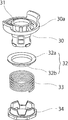
- FIG. 2 is a schematic exploded perspective view showing a bypass valve assembly which is a main part of the thermostat device of FIG. It is a table
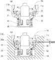
- (A), (b) is principal part sectional drawing for demonstrating the state before assembling the thermostat apparatus based on this invention to an apparatus body. It is a schematic perspective view which shows the external appearance of the thermostat apparatus of Fig.1 (a). It is a cooling water circuit diagram of the engine for vehicles which applies the thermostat device concerning the present invention.
- an outlet control thermostat device provided mainly on the engine cooling water outlet side is opened by the differential pressure of cooling water flowing through the engine outlet passage and the return passage leading to the engine inlet.
- a pressure valve (bypass valve) for bypassing the passage and the return passage and a bypass passage are integrally incorporated in a device frame that also serves as a spring receiver for a coil spring that biases the main valve.
- FIGS. 1 and 6 show an embodiment of a thermostat device according to the present invention.
- the thermostat device generally indicated by reference numeral 10 has the structure shown in FIGS. 1 and 6 and is provided in the engine coolant outlet side in the automobile coolant circuit shown in FIG. .
- Reference numeral 1 denotes an engine, and a radiator 3 is connected to the outlet of the cooling water via a radiator passage 2.
- the return passage 4 is connected to the engine cooling water inlet to constitute a cooling water cooling circuit.
- a water pump (W / P) 5 is provided at the engine coolant inlet.
- a thermostat device 10 characterizing the present invention is provided on the engine coolant outlet side of the radiator passage 2, and a bypass passage 6 (corresponding to a communication hole 31 described later) branched here is upstream of the water pump 5. Connected to the side.
- the heater passage 8 sends the cooling water from the engine 1 to the heater 7 and warms the air in the passenger compartment.
- the engine 10 is configured to return to the engine 1 through 10. If the heater passage 8 is connected to the return passage 4 from the radiator 3 upstream of the water pump 5 (W / P), even before the return passage 4 and the bypass passage 6 are connected, after connection. There may be. Here, it is connected to the position before connection.
- the cooling water heated by the engine 1 is sent to the radiator 3, the cooling water temperature is lowered, and the water pump 5 introduces the cooling water into the engine 1, thereby cooling the engine 1. It has become.
- the thermostat device 10 flows back to the engine 1 via the bypass passage 6 (communication hole 31) so as to bypass the radiator 3. It has a path switching function.
- the thermostat device 10 includes a device housing 11 having a substantially dome shape as a whole, and a passage 12 connected to the radiator passage 2 toward the radiator 3 is opened in a part thereof. Is provided.
- the device housing 11 is used by being bolted to the jacket portion 1A of the engine 1 or the like.
- a single device body may be used, and an appropriate passage may be formed in the device body.
- reference numeral 13 denotes an engine outlet passage, which is configured to feed the cooling water in the engine 1 to the heater 7 side.
- Reference numeral 14 denotes a main valve of the thermostat device 10 for connecting and blocking the engine outlet passage 13 and the passage 12 to the radiator 3, and the valve body (the first valve body from the relationship with the second valve body described later). By opening and closing the part), the cooling water from the engine 1 is selectively fed to the radiator 3 side.
- reference numeral 15 denotes a thermo element, which is configured to control opening and closing of the first valve body serving as the main valve 14 by driving the piston 15 a to extend and contract according to the engine coolant temperature in the engine outlet passage 13.
- a main spring 16 is a coil spring that biases the first valve body in the main valve 14 in the valve closing direction.
- the engine jacket portion 1A as the device body is formed with a return passage 20 for returning cooling water from the heater 8 or the radiator 3 to the engine inlet via the water pump 5, and corresponds to the mounting portion of the thermostat device 10.
- spaces 21 and 22 are formed in the passages 13 and 20, respectively.
- the opening 23 which connects these space parts 21 and 22 is formed.
- the device frame has a substantially cylindrical shape and is configured to be latched and held by a pair of legs 11 b and 11 c suspended from the device housing 11. .
- Reference numeral 32 in FIG. 3 is a second valve body composed of a ring-shaped member having a substantially L-shaped cross section so as to exhibit a shape having a flange-shaped cross section, for opening and closing the communication hole 31.
- the guide cylinder 32b is movably fitted to the cylindrical portion of the apparatus frame 30 and is provided by the valve section 32a of the second valve body 32.
- the communication hole 31 formed in the flange-shaped portion 30a is opened and closed so that the bypass passage 6 communicates.
- the second valve body 32 is urged by a coil spring 33 as a sub spring, and is assembled and held by a stopper 34 fitted and locked to the distal end of the cylindrical portion of the apparatus frame 30, whereby the sub valve assembly Is configured.
- the cross-sectional shape of the second valve body 32 does not necessarily have to be a flange shape or a substantially inverted L shape, and in summary, the shape of the communication hole 31 such as one having a projection shape that fits into the communication hole 31.
- the shape of the communication hole 31 such as one having a projection shape that fits into the communication hole 31.
- any shape can be used as long as it can be closed in accordance with the above.
- the second valve body 32 constituting the sub-valve is opened and closed while the biasing force of the coil spring 34 is deflected by the pressure difference between the passages 21 and 22 regardless of the movement of the thermo element 15. It has become.
- the guide cylinder 32b of the second valve body 32 described above does not necessarily have to extend over the entire circumference, and may have several protrusions in the circumferential direction.
- the second valve body 32 is movable in the axial direction around the cylindrical portion of the device frame 30, and the passage hole 31 while bending the coil spring 33 due to the pressure difference between the passages 21 and 22.
- the bypass passage 6 may be configured to communicate with each other.
- the sub-valve assembly According to the sub-valve assembly described above, it can be easily assembled and held with respect to the legs 11b and 11c of the device housing 11 constituting the thermostat device 10. In this assembled state, the device frame 30 is locked by the main spring 16 to the front end claw portions of the legs 11b and 11c of the device housing 11 so that the assembled state is maintained.
- reference numeral 25 in FIGS. 1 and 2 denotes a rubber ring that is fitted and held on the outer side of the flange-shaped portion 30a of the apparatus frame 30 and is interposed between the opening 23 and the first passage.
- the seal between the engine outlet passage 13 and the return passage 20 as the third passage may be ensured.
- this rubber ring 25 may be provided so as to be sandwiched between the opening 23, the flange-like portion 30 a of the apparatus frame 30, and the opening 23 regardless of the above-described interposition position.
- the thermostat device 10 assembled with such a sub-valve assembly includes a sub-valve assembly including a device frame 30 with respect to an assembly portion by the space portion 21, the opening 23, and the space portion 22 of the engine jacket portion 1A as the device body. Then, the thermo element 15 portion is inserted, and the flange-like portion 30a of the device frame 30 is brought into contact with the step portion of the opening 23, whereby the assembly to the device body is completed. At this time, the apparatus frame 30 is pressed by the main spring 16 and stably supported on the apparatus body 11A side.
- FIG. 5A the thermostat device 10 to which the above-described sub-valve assembly is assembled is shown in FIG. 5A.
- the device frame 30 that is locked to the tips of the legs 11b and 11c of the device housing 11 is shown.
- the flange-shaped portion 30a is locked and held by being pressed and urged by the main spring 16 constituting the main valve, and an assembly as the thermostat device 10 is configured.
- the engine outlet passage 13 and the return passage 20 are provided in parallel in the device body (engine jacket portion) 1A, and the thermostat device 10 is installed by being inserted into the portion having the space portions 21 and 22.
- the assembly is fixed.
- the apparatus housing 11 is assembled to the apparatus body 1A at the time of this assembly and fixing, the apparatus frame 30 is released from the locked state as shown in FIG.
- the device body 1A is pressed and urged and assembled. At this time, a slight gap is formed between the distal end locking portions of the leg portions 11 b and 11 c of the device housing 11 and the flange-like portion 30 a of the device frame 30 so as to be separated.
- the device frame 30 that is pressed and urged by the main spring 16 is reliably pressed and held on the device body 1A side, whereby a stable assembled and fixed state is obtained, and assemblability is improved. .
- the operation relationship between the main valve 14 and the bypass valve and the return passage 20 in the thermostat device 10 obtained in this way is as shown in FIG. That is, the main valve is closed before warming up and is open after warming up. On the other hand, the return passage 20 is always open.
- the bypass valve (sub-valve) is closed at low speed and open at high speed, regardless of whether it is warming up or after warming up.
- the thermostat valve (15) and the second valve body 32 are assembled by assembling the sub valve assembly together with the first valve body 15 and the main spring 16 that are the main valves constituting the thermostat device 10. And can be provided as a unitary structure.
- the device frame 30 is a member that also serves as a guide member for the thermo element 15 and also serves as a spring receiver for the main spring 16, has a small number of components, is excellent in terms of assembly, and reduces cost. There is also an advantage such as aiming.
- the above-described configuration has advantages in that the degree of freedom in the layout as the thermostat device 10 is increased and the engine 1 can be downsized.
- the communication hole 31 (bypass passage 6) is formed integrally with the apparatus frame 30, and the second valve body serving as the bypass valve is easily produced by press molding with metal or integral molding with resin. It is possible, the structure is simple, and the productivity can be improved.
- both the passages can be isolated with a simple structure by the apparatus frame 30 and the rubber ring 25 without using a special seal structure between the first passage and the third passage, and the thermostat.
- the apparatus 10 can be easily assembled to the jacket portion 1A of the engine 1, the assemblability can be improved, and the manufacturing cost can be reduced.
- the present invention is not limited to the structure described in the above-described embodiment, and it goes without saying that the shape, structure, and the like of each part constituting the thermostat device 10 can be appropriately modified and changed.
- a thermostat device used in a cooling water device for an automobile engine of the type using an electric water pump W / P that is not linked to the engine speed can be applied and exhibit an effect.
Landscapes
- Engineering & Computer Science (AREA)
- Chemical & Material Sciences (AREA)
- Combustion & Propulsion (AREA)
- Mechanical Engineering (AREA)
- General Engineering & Computer Science (AREA)
- Physics & Mathematics (AREA)
- General Physics & Mathematics (AREA)
- Automation & Control Theory (AREA)
- Temperature-Responsive Valves (AREA)
Abstract
【課題】 エンジン冷却水の流れを制御するサーモスタット装置に対しバイパス通路やバイパスバルブ等としての機能をも付加し、しかも全体の構造の簡素化、組立性を向上させ、コスト低減を図ることも可能とする。 【解決手段】 自動車用エンジン1の冷却水回路中に設けられ第1、第2の通路13,12間での冷却水の流れを制御するメインバルブ14と前記第1の通路内に配置され冷却水温度に従って前記メインバルブを駆動制御するサーモエレメント15とを備える。サーモスタット装置10が組み込まれた装置ボディ1Aは第3の通路20を備える。そして、エンジン冷却水回路内での冷却水圧力が所定圧以上になったときに該第1の通路と第3の通路とを連通させる連通孔を開閉する第2弁体32を、前記サーモエレメントを保持する装置フレーム30に一体的に組付けて設ける。
Description
本発明は、自動車用エンジンの冷却水回路中に設けられ冷却水温度に従って冷却水の流れを適宜制御するためのサーモスタット装置に関し、主にエンジン出口に設けられ、いわゆるエンジン出口側制御を行うサーモスタット装置に関する。
従来この種のサーモスタット装置としては、種々の構造のものが知られており、例えば自動車用エンジンの冷却水回路において、冷却水の流れを、該冷却水温度にしたがって制御するものであり、エンジンの冷却水出口側あるいは冷却水入口側に適宜の状態で組込み配置されている。
この種のサーモスタット装置において、近年では、暖機性能を向上させ、かつエンジンを即暖させるために、サーモスタットが開く前の冷却水温度が低い際、バイパス通路を小さくし、車室内暖房用のヒータ通路への冷却水をより多く流すように設計されることが多くなっている。しかし、暖機前にエンジンの回転数が高くなりエンジン高負荷状態になると、それに連動駆動するウォーターポンプの回転数が上昇し、冷却水回路内の圧力が高くなってしまい、ヒータ、ラジエータ、さらには配管の破裂等を招いてしまう虞れがある。
このため、冷却水回路内の圧力(ウォーターポンプの吸引力)が所定圧力なった場合に、エンジン出口通路からバイパス通路側に冷却水を流すようにエンジン出口通路とエンジン戻り通路との間にバイパス通路を設けるとともに、サーモスタットバルブとは別にバイパスバルブを設けたものが従来から知られている(例えば、特許文献1参照)。
また、エンジンの冷却水入口側に設けられるサーモスタット装置において、エンジン入口に至る戻り通路とバイパス通路との間を開閉するバイパスバルブを、該サーモスタット装置におけるサーモエレメント構成部材の端部に組付けて構成したものも知られている(例えば、特許文献2参照)。
しかし、上述した従来構造において、前者の場合には、サーモスタットバルブに加えて別個にバイパスバルブを構成するための構成部品点数が多くなり、構造が複雑化するとともに、組立ても面倒かつ煩雑で、コスト高を招くといった問題があった。
また、後者の場合には、エンジンの冷却水入口側に設けられるタイプのサーモスタット装置では、ある程度の効果は得られるものの、エンジンの冷却水出口側に設けられるタイプのサーモスタット装置として、そのまま転用することは、構造上不可能であり、何らかの対策を講じる必要性が生じている。
さらに、上述した従来構造によれば、バイパスバルブ用のコイルばねがサーモエレメントにより他端を固定されているため、温度によるサーモエレメントの進退運動により、バイパスバルブに付勢されるばね荷重が変化してしまう。例えば、サーモエレメントが作動していないときのばね荷重よりも、サーモエレメントが作動し反メインバルブ側に移動するに従ってばね荷重は高くなり、結果としてバイパスバルブが開閉する設定圧力が変化してしまい、適切な一定圧力に制御し難いという問題もあり、これらの問題点を一掃し得る対策を講じることが望まれている。
本発明はこのような事情に鑑みてなされたものであり、エンジン冷却水の流れを制御するサーモスタットバルブに対しバイパス通路やバイパスバルブとしての機能をも付加し、しかも全体としての構成の簡素化、部品点数の削減、組立性の向上を図り、コスト低減を可能とするサーモスタット装置を得ることを目的とする。
このような目的に応えるために本発明(請求項1記載の発明)に係るサーモスタット装置は、自動車用エンジンの冷却水回路中に設けられ第1、第2の通路間での冷却水の流れを制御するメインバルブと前記第1の通路内に配置され冷却水温度に従って前記メインバルブを駆動制御するサーモエレメントとを備えたサーモスタット装置であって、前記サーモスタット装置が組み込まれた装置ボディは第3の通路を備え、前記冷却水回路内での冷却水圧力が所定圧以上になったときに該第1の通路と第3の通路とを連通させる連通孔を開閉する第2弁体を、前記サーモエレメントを保持する装置フレームに一体的に設けたことを特徴とする。
本発明(請求項2記載の発明)に係るサーモエレメント装置は、請求項1において、前記第2弁体は、前記サーモエレメントを保持する前記装置フレームと同軸上で移動可能に配置するとともに、コイルばねで付勢することにより、前記サーモエレメントの動きには無関係に、前記装置フレームの一部に設けた連通孔を塞ぐように構成したことを特徴とする。
本発明(請求項3記載の発明)に係るサーモスタット装置は、請求項1または請求項2において、前記第2弁体を付勢するコイルばねは、前記装置フレームの筒状部端部とストッパとの係合により保持されるように構成されていることを特徴とする。
本発明(請求項4記載の発明)に係るサーモスタット装置は、請求項1ないし請求項3のいずれか1項において、前記装置ボディは、前記第1の通路と前記第3の通路とを連通させる開口を前記サーモエレメントと同軸上に有し、前記開口には装置フレームの筒状部が嵌合保持され、この装置フレームは、前記メインバルブを付勢するメインスプリングにより押圧されることにより前記装置ボディに当接して係止されることにより、前記第1の通路と第3の通路とが隔離されていることを特徴とする。
本発明(請求項5記載の発明)に係るサーモスタット装置は、請求項1ないし請求項4のいずれか1項において、前記サーモスタット装置は前記メインバルブを構成する第1弁体とこれを駆動制御するサーモエレメントを支持する装置ハウジングを備え、前記装置フレームは、前記サーモエレメントに嵌装されることにより該サーモエレメントを移動可能に保持した状態で、前記装置ハウジングの一部に前記メインスプリングの付勢力で押圧されて係止され、この状態で前記装置ハウジングを前記装置ボディに組み付けることにより、前記装置フレームは、前記係止状態が解除されるとともに、前記メインスプリングで前記装置ボディ側に押圧付勢されて組み付けられていることを特徴とする。
以上説明したように本発明に係るサーモスタット装置によれば、第2弁体やこれにより開閉されるバイパス通路を装置フレームに一体的に設けたことにより、従来構造のようにバイパスバルブ(第2弁体)をサーモスタットバルブと別体に構成する必要はなく、サーモスタット装置として一体的に構成できるため、構成部品点数の削減を図り、サーモスタットのレイアウトの自由度が大きくすることが可能で、これにより冷却水系を含めたエンジン回りでの小型化を達成することも可能となる。
特に、本発明によれば、前述した特許文献2のような問題点を解決でき、サーモエレメントとの作動状況に関係なく、一定のばね荷重が設定可能となるため、バイパスバルブ用のコイルばねの設計が容易になる。
また、本発明によれば、第2弁体をサーモエレメントと同軸上に配置することにより、装置フレームと連通孔とを一体成型(樹脂・金属どちらでもよい)すること可能で、また第2弁体も金属製の場合はプレス成型、樹脂製の場合は一体成型が可能となり、簡単な構造であるため、この第2のバルブを構成する部品を容易に作製することができ、これにより生産性を向上させ、また全体のコスト低減を図ることができる。
さらに、本発明によれば、第2弁体の組付けを、簡単な構造でかつ安価なコイルばねを採用して行えるため、組立性も向上し、製造コストも低減させることができる。
また、本発明によれば、第1通路と第3通路との間を特別なシール構造を用いることなく、より簡易な構造で両通路を隔離することができ、サーモスタット装置をエンジンに組付けることが容易になり、組立性も向上し、製造コストも低減させることができる。
自動車用エンジンの冷却水回路で主にエンジンの冷却水出口側に設けられる出口制御用のサーモスタット装置において、エンジン出口通路とエンジン入口に至る戻り通路とを流れる冷却水の差圧により開き、エンジン出口通路と戻り通路とをバイパスさせる圧力弁(バイパスバルブ)及びバイパス通路を、メインバルブを付勢するコイルばねのばね受けともなる装置フレームに一体的に組み込んで構成するようにする。
図1ないし図7は本発明に係るサーモスタット装置の一実施例を示す。
これらの図において、全体を符号10で示すサーモスタット装置は、図1、図6に示す構造を有し、図7で示す自動車用エンジンの冷却水回路においてエンジン冷却水出口側に組み込まれて設けられる。
これらの図において、全体を符号10で示すサーモスタット装置は、図1、図6に示す構造を有し、図7で示す自動車用エンジンの冷却水回路においてエンジン冷却水出口側に組み込まれて設けられる。
まず、本発明に係るサーモスタット装置10を適用する冷却水回路の概要を図7を用いて簡単に説明すると、符号1はエンジン、その冷却水出口にはラジエータ通路2を介してラジエータ3が接続され、戻り通路4がエンジン冷却水入口に接続され、冷却水の冷却回路が構成されている。5はウォータポンプ(W/P)で、エンジン冷却水入口に設けられている。
前記ラジエータ通路2のエンジン冷却水出口側には、本発明を特徴づけるサーモスタット装置10が設けられ、ここで分岐されたバイパス通路6(後述する連通孔31が相当する)が前記ウォータポンプ5の上流側に接続されている。
7は車内空調用の熱交換器であるヒータ、8はヒータ通路であり、このヒータ通路8は、エンジン1からの冷却水をヒータ7に送り、車室内空気等を温めた後、前記サーモスタット装置10を経てエンジン1に戻すように構成されている。なお、ラジエータ3からの戻り通路4へのヒータ通路8の接続は、ウォータポンプ5(W/P)の上流であれば、戻り通路4とバイパス通路6との接続前であっても接続後であってもよい。ここでは、接続前の位置に接続している。
上述した冷却水回路によれば、エンジン1で熱せられた冷却水をラジエータ3に送り、冷却水温度を低下させ、ウォータポンプ5でエンジン1内に導入することにより、エンジン1を冷却するようになっている。ここで、前記サーモスタット装置10は、周知の通り、エンジン1からの冷却水温度が低いときには、ラジエータ3を迂回させるように、バイパス通路6(連通孔31)を介してエンジン1に戻したりする流路切換え機能をもつものである。
前記サーモスタット装置10は、図1、図6に示されるように、全体がほぼドーム状を呈する装置ハウジング11を備え、その一部にはラジエータ3に向かうラジエータ通路2につながる通路12が開口して設けられている。
ここで、この装置ハウジング11は、エンジン1のジャケット部1A等にボルト止めされることで使用される。なお、このジャケット部1Aの代わりに、単独の装置ボディを用い、これに適宜の通路を形成してもよい。
ここで、この装置ハウジング11は、エンジン1のジャケット部1A等にボルト止めされることで使用される。なお、このジャケット部1Aの代わりに、単独の装置ボディを用い、これに適宜の通路を形成してもよい。
図1中13はエンジン出口通路であり、エンジン1内の冷却水をヒータ7側に給送するように構成されている。14はこのエンジン出口通路13と前記ラジエータ3への通路12とを接続、遮断するサーモスタット装置10のメインバルブであり、その弁体(後述する第2弁体との関係から第1弁体となる部分)が開閉動作することにより、エンジン1からの冷却水を選択的にラジエータ3側に給送するようになっている。
図1中15はサーモエレメントであり、エンジン出口通路13中のエンジン冷却水温度によってピストン15aを伸縮駆動することにより、前記メインバルブ14となる第1弁体を開閉制御するように構成されている。なお、16はメインバルブ14における第1弁体を弁閉方向に付勢するコイルばねによるメインスプリングである。
前記装置ボディとしてのエンジンジャケット部1Aには、前記ヒータ8またはラジエータ3からウォータポンプ5を経てエンジン入口に冷却水を還流させるための戻り通路20が形成され、前記サーモスタット装置10の取付部に対応して各通路13,20に空間部21,22が形成されている。さらにこれらの空間部21,22を連通させる開口23が形成されている。
図中符号30で示すものは、本発明を特徴づけるサブバルブ(バイパスバルブ)を構成する連通孔31(バイパス通路6)をフランジ状部30aに有し全体が前記開口23に嵌合するように形成されたほぼ筒状を呈する装置フレームであり、図3、図4から明らかなように、前記装置ハウジング11から垂下された一対の脚部11b、11cに係止保持されるように構成されている。
図3中符号32はフランジ状断面を有する形状を呈するように、例えば、断面がほぼ逆L字形状を呈するリング状部材で構成される第2弁体であり、前記連通孔31を開閉するための弁部32aとガイド筒32bからなり、このガイド筒32bが前記装置フレーム30の筒状部に移動自在に嵌装して設けられ、この第2弁体32の弁部32aによって前記装置フレーム30のフランジ状部30aに形成されている連通孔31が開閉され、バイパス通路6が連通するように構成されている。この第2弁体32はサブスプリングとしてのコイルばね33により付勢され、かつ装置フレーム30の筒状部先端に嵌合して係止されたストッパ34により組付け保持され、これによりサブバルブ組立体が構成されている。
ここで、この第2弁体32の断面形状は、必ずしもフランジ状あるいはほぼ逆L字形状でなくともよく、要は連通孔31に嵌合する突起状形状を有するもの等、連通孔31の形状に応じて閉じることができる形状であれば、どのような形状でもよいことは勿論である。
そして、このサブバルブを構成する第2弁体32は、前記サーモエレメント15の動きとは無関係に、前記通路21,22間の圧力差によってコイルばね34の付勢力を撓ませながら開閉動作するようになっている。
なお、上述した第2弁体32のガイド筒32bは、必ずしも全周に渡るものでなくてもよく、周方向の数カ所の突起状になっていてもよい。要は、この第2弁体32が装置フレーム30の筒状部の回りで軸線方向に移動可能になっており、かつ通路21,22間の圧力差でコイルばね33を撓ませながら通路孔31を開閉され、バイパス通路6が連通するように構成されておればよい。
なお、上述した第2弁体32のガイド筒32bは、必ずしも全周に渡るものでなくてもよく、周方向の数カ所の突起状になっていてもよい。要は、この第2弁体32が装置フレーム30の筒状部の回りで軸線方向に移動可能になっており、かつ通路21,22間の圧力差でコイルばね33を撓ませながら通路孔31を開閉され、バイパス通路6が連通するように構成されておればよい。
上述したサブバルブ組立体によれば、これをサーモスタット装置10を構成する装置ハウジング11の脚部11b,11cに対して簡単に組付けて保持することができる。この組立状態では、前記装置フレーム30はメインスプリング16により装置ハウジング11の脚部11b,11cの先端爪部に係止され、その組立状態が維持されるようになっている。
ここで、図1,2中符号25は装置フレーム30のフランジ状部30aの外側に嵌装されて保持されるゴムリングであり、開口23との間に介装することにより、第1の通路であるエンジン出口通路13と第3の通路である戻り通路20とのシールを確実にするようにしてもよい。勿論、このゴムリング25は上述した介装位置には拘らず、開口23と装置フレーム30のフランジ状部30aと開口23との間にサンドイッチ状に挟まれるように介在させて設けても良い。
また、このようなサブバルブ組立体を組付けたサーモスタット装置10を、装置ボディであるエンジンジャケット部1Aの空間部21、開口23、空間部22による組付け部分に対し装置フレーム30を含むサブバルブ組立体、サーモエレメント15部分を挿入し、装置フレーム30のフランジ状部30aを開口23の段部に当接させることで、装置ボディへの組付けが完了する。このとき、装置フレーム30はメインスプリング16に押圧されて装置ボディ11A側に安定して支持される。
ここで、上述したサブバルブ組立体を組み付けたサーモスタット装置10を、図5(a)に示しており、この組立時には、装置ハウジング11の脚部11b,11cの先端に係止される装置フレーム30のフランジ状部30aは、メインバルブを構成するメインスプリング16により押圧付勢されることにより係止保持され、サーモスタット装置10としての組立体が構成される。
上述したサーモスタット装置10は、装置ボディ(エンジンジャケット部)1Aにおいてエンジン出口通路13、戻り通路20が並列して設けられており、前記空間部21,22を有する部分に対し差込んで装着することで、組付け固定される。
この組付け固定時において、前記装置ハウジング11を装置ボディ1Aに組み付けることにより、装置フレーム30は、図5(b)に示すように、前記係止状態が解除されるとともに、前記メインスプリング16で前記装置ボディ1A側に押圧付勢されて組み付けられることになる。このとき、前記装置ハウジング11の脚部11b、11cの先端係止部分と装置フレーム30のフランジ状部30aとの間には若干の隙間が形成されて離間している。
この組付け固定時において、前記装置ハウジング11を装置ボディ1Aに組み付けることにより、装置フレーム30は、図5(b)に示すように、前記係止状態が解除されるとともに、前記メインスプリング16で前記装置ボディ1A側に押圧付勢されて組み付けられることになる。このとき、前記装置ハウジング11の脚部11b、11cの先端係止部分と装置フレーム30のフランジ状部30aとの間には若干の隙間が形成されて離間している。
このように構成することにより、メインスプリング16で押圧付勢される装置フレーム30は、装置ボディ1A側に確実に押圧保持され、これにより安定した組付け固定状態が得られ、組付け性がよくなる。
また、このようにして得られるサーモスタット装置10におけるメインバルブ14とバイバスバルブ、さらに戻り通路20の作動関係は、図4に示すようになっている。すなわち、暖機前にはメインバルブは閉じており、暖機後は開状態となる。一方、戻り通路20は常時開路となっている。また、バイバスバルブ(サブバルブ)は、暖機前、暖機後とは無関係に、低回転時には閉、高回転時には開となる。
以上の構成によれば、サーモスタット装置10を構成するメインバルブである第1弁体15、メインスプリング16等と共に、前記サブバルブ組立体を組付けることにより、サーモスタットバルブ(15)と第2弁体32とを一体的に備えた構造とすることができる。しかも、この場合に、上記の装置フレーム30は、サーモエレメント15のガイド部材として、さらにメインスプリング16のばね受けも兼ねる部材であり、構成部品点数も少なく、組立性の面でも優れ、コスト低減が図る等の利点もある。また、上述した構成では、サーモスタット装置10としてのレイアウト上での自由度が大きくなり、エンジン1の小型化も達成できる等の利点もある。
また、上述した構成によれば、装置フレーム30に連通孔31(バイパス通路6)を一体に成型し、さらにバイパスバルブとなる第2弁体も金属によるプレス成型または樹脂による一体成形で簡単に作製可能であり、構造も簡単で、生産性も向上させることができる。
さらに、上述した構成によれば、簡単な構造かつ安価なコイルばねを採用することができるため、組立性も向上し、製造コストも低減させることができる。
また、上述した構成によれば、第1通路と第3通路間を特別なシール構造を用いることなく、装置フレーム30とゴムリング25とにより簡易な構造で両通路を隔離することができ、サーモスタット装置10をエンジン1のジャケット部1Aに組付けることが容易になり組立性も向上し、製造コストも低減させることができる。
また、上述した構成によれば、第1通路と第3通路間を特別なシール構造を用いることなく、装置フレーム30とゴムリング25とにより簡易な構造で両通路を隔離することができ、サーモスタット装置10をエンジン1のジャケット部1Aに組付けることが容易になり組立性も向上し、製造コストも低減させることができる。
なお、本発明は上述した実施の形態で説明した構造には限定されず、サーモスタット装置10を構成する各部の形状、構造等を適宜変形、変更し得ることはいうまでもない。
例えばエンジン回転数とは連動しない電動式ウォータポンプW/Pを用いたタイプの自動車用エンジンの冷却水装置に用いるサーモスタット装置であっても適用して効果を発揮し得るものである。
例えばエンジン回転数とは連動しない電動式ウォータポンプW/Pを用いたタイプの自動車用エンジンの冷却水装置に用いるサーモスタット装置であっても適用して効果を発揮し得るものである。
1 エンジン
1A エンジンジャケット部(装置ボディ)
2 ラジエータ通路
3 ラジエータ
4 戻り通路
5 ウォータポンプ
7 ヒータ
8 ヒータ通路
10 サーモスタット装置
11 装置ハウジング
12 通路(ラジエータ側通路)
13 エンジン出口通路
14 メインバルブ(第1弁体)
15 サーモエレメント
16 メインスプリング
20 戻り通路
21 空間部
22 空間部
23 開口
25 ゴムリング
30 装置フレーム
30a フランジ状部
31 連通孔(バイパス通路)
32 第2弁体
33 コイルばね
34 ストッパ
1A エンジンジャケット部(装置ボディ)
2 ラジエータ通路
3 ラジエータ
4 戻り通路
5 ウォータポンプ
7 ヒータ
8 ヒータ通路
10 サーモスタット装置
11 装置ハウジング
12 通路(ラジエータ側通路)
13 エンジン出口通路
14 メインバルブ(第1弁体)
15 サーモエレメント
16 メインスプリング
20 戻り通路
21 空間部
22 空間部
23 開口
25 ゴムリング
30 装置フレーム
30a フランジ状部
31 連通孔(バイパス通路)
32 第2弁体
33 コイルばね
34 ストッパ
Claims (5)
- 自動車用エンジンの冷却水回路中に設けられ第1、第2の通路間での冷却水の流れを制御するメインバルブと前記第1の通路内に配置され冷却水温度に従って前記メインバルブを駆動制御するサーモエレメントとを備えたサーモスタット装置であって、
前記サーモスタット装置が組み込まれた装置ボディは第3の通路を備え、
前記冷却水回路内での冷却水圧力が所定圧以上になったときに該第1の通路と第3の通路とを連通させる連通孔を開閉する第2弁体を、前記サーモエレメントを保持する装置フレームに一体的に設けたことを特徴とするサーモエレメント装置。 - 請求項1記載のサーモスタット装置において、
前記第2弁体は、前記サーモエレメントを保持する前記装置フレームと同軸上で移動可能に配置するとともに、コイルばねで付勢することにより、前記サーモエレメントの動きには無関係に、前記装置フレームの一部に設けた連通孔を塞ぐように構成したことを特徴とするサーモスタット装置。 - 請求項1または請求項2記載のサーモスタット装置において、
前記第2弁体を付勢するコイルばねは、前記装置フレームの筒状部端部とストッパとの係合により保持されるように構成されていることを特徴とするサーモスタット装置。 - 請求項1ないし請求項3のいずれか1項に記載のサーモスタット装置において、
前記装置ボディは、前記第1の通路と前記第3の通路とを連通させる開口を前記サーモエレメントと同軸上に有し、
前記開口には装置フレームの筒状部が嵌合保持され、
この装置フレームは、前記メインバルブを付勢するメインスプリングにより押圧されることにより前記装置ボディに当接して係止されることにより、前記第1の通路と第3の通路とが隔離されていることを特徴とするサーモスタット装置。 - 請求項1ないし請求項4のいずれか1項に記載のサーモスタット装置において、
前記サーモスタット装置は前記メインバルブを構成する第1弁体とこれを駆動制御するサーモエレメントを支持する装置ハウジングを備え、
前記装置フレームは、前記サーモエレメントに嵌装されることにより該サーモエレメントを移動可能に保持した状態で、前記装置ハウジングの一部に前記メインスプリングの付勢力で押圧されて係止され、
この状態で前記装置ハウジングを前記装置ボディに組み付けることにより、前記装置フレームは、前記係止状態が解除されるとともに、前記メインスプリングで前記装置ボディ側に押圧付勢されて組み付けられていることを特徴とするサーモスタット装置。
Priority Applications (2)
| Application Number | Priority Date | Filing Date | Title |
|---|---|---|---|
| CN201280068656.6A CN104093950A (zh) | 2012-01-31 | 2012-10-04 | 恒温装置 |
| EP12867217.7A EP2811134A4 (en) | 2012-01-31 | 2012-10-04 | THERMOSTAT |
Applications Claiming Priority (2)
| Application Number | Priority Date | Filing Date | Title |
|---|---|---|---|
| JP2012019232A JP5936868B2 (ja) | 2012-01-31 | 2012-01-31 | サーモスタット装置 |
| JP2012-019232 | 2012-01-31 |
Publications (1)
| Publication Number | Publication Date |
|---|---|
| WO2013114676A1 true WO2013114676A1 (ja) | 2013-08-08 |
Family
ID=48904743
Family Applications (1)
| Application Number | Title | Priority Date | Filing Date |
|---|---|---|---|
| PCT/JP2012/075770 Ceased WO2013114676A1 (ja) | 2012-01-31 | 2012-10-04 | サーモスタット装置 |
Country Status (4)
| Country | Link |
|---|---|
| EP (1) | EP2811134A4 (ja) |
| JP (1) | JP5936868B2 (ja) |
| CN (1) | CN104093950A (ja) |
| WO (1) | WO2013114676A1 (ja) |
Cited By (3)
| Publication number | Priority date | Publication date | Assignee | Title |
|---|---|---|---|---|
| WO2019013730A3 (en) * | 2017-04-14 | 2019-04-25 | Kirpart Otomotiv Parcalari Sanayi Ve Ticaret A.S. | THERMOSTAT ASSEMBLY WITH DOUBLE FLOW SLEEVE VALVE STRUCTURE AND PRESSURE BALANCE |
| WO2022176872A1 (ja) * | 2021-02-17 | 2022-08-25 | 日本サーモスタット株式会社 | サーモスタット装置 |
| US20240093630A1 (en) * | 2021-02-17 | 2024-03-21 | Nippon Thermostat Co., Ltd. | Thermostat device |
Families Citing this family (3)
| Publication number | Priority date | Publication date | Assignee | Title |
|---|---|---|---|---|
| CN106545402B (zh) * | 2015-09-17 | 2019-04-05 | 上海世德子汽车零部件有限公司 | 电阻丝加热节温器及发动机冷却系统 |
| KR101694064B1 (ko) * | 2015-10-13 | 2017-01-06 | 현대자동차주식회사 | 자동차용 오일 써모스탯 |
| TR201714299A1 (tr) * | 2017-09-26 | 2019-04-22 | Kirpart Otomotiv Parcalari Sanayi Ve Ticaret A S | Geli̇şti̇ri̇lmi̇ş bypass kontrolüne sahi̇p termostat terti̇bati |
Citations (5)
| Publication number | Priority date | Publication date | Assignee | Title |
|---|---|---|---|---|
| JPS61201816A (ja) * | 1985-03-04 | 1986-09-06 | Daihatsu Motor Co Ltd | エンジンの冷却装置 |
| JPS61147326U (ja) * | 1985-03-04 | 1986-09-11 | ||
| JPH0371127U (ja) | 1989-11-14 | 1991-07-18 | ||
| JPH0988598A (ja) | 1995-09-27 | 1997-03-31 | Daihatsu Motor Co Ltd | サーモスタット弁 |
| JP2009537740A (ja) * | 2006-05-23 | 2009-10-29 | ベール テルモト−トロニク ゲゼルシャフト ミット ベシュレンクテル ハフツング | サーモスタット弁 |
Family Cites Families (6)
| Publication number | Priority date | Publication date | Assignee | Title |
|---|---|---|---|---|
| DE4427340A1 (de) * | 1993-08-07 | 1995-02-09 | Bayerische Motoren Werke Ag | Thermostatventil |
| JP4659769B2 (ja) * | 2007-01-25 | 2011-03-30 | トヨタ自動車株式会社 | 冷却装置 |
| JP4384230B2 (ja) * | 2008-03-19 | 2009-12-16 | ダイハツ工業株式会社 | エンジンの冷却装置 |
| CN101598061B (zh) * | 2008-06-03 | 2013-02-20 | 刘传鹏 | 发动机冷却系统 |
| CN201363190Y (zh) * | 2009-01-12 | 2009-12-16 | 广西玉柴机器股份有限公司 | 一种节温器 |
| DE102009008898A1 (de) * | 2009-02-13 | 2010-08-19 | Gustav Wahler Gmbh U. Co. Kg | Thermostatventil zur Regelung der Temperatur des Kühlmittels einer Brennkraftmaschine |
-
2012
- 2012-01-31 JP JP2012019232A patent/JP5936868B2/ja active Active
- 2012-10-04 CN CN201280068656.6A patent/CN104093950A/zh active Pending
- 2012-10-04 WO PCT/JP2012/075770 patent/WO2013114676A1/ja not_active Ceased
- 2012-10-04 EP EP12867217.7A patent/EP2811134A4/en not_active Withdrawn
Patent Citations (5)
| Publication number | Priority date | Publication date | Assignee | Title |
|---|---|---|---|---|
| JPS61201816A (ja) * | 1985-03-04 | 1986-09-06 | Daihatsu Motor Co Ltd | エンジンの冷却装置 |
| JPS61147326U (ja) * | 1985-03-04 | 1986-09-11 | ||
| JPH0371127U (ja) | 1989-11-14 | 1991-07-18 | ||
| JPH0988598A (ja) | 1995-09-27 | 1997-03-31 | Daihatsu Motor Co Ltd | サーモスタット弁 |
| JP2009537740A (ja) * | 2006-05-23 | 2009-10-29 | ベール テルモト−トロニク ゲゼルシャフト ミット ベシュレンクテル ハフツング | サーモスタット弁 |
Non-Patent Citations (1)
| Title |
|---|
| See also references of EP2811134A4 * |
Cited By (7)
| Publication number | Priority date | Publication date | Assignee | Title |
|---|---|---|---|---|
| WO2019013730A3 (en) * | 2017-04-14 | 2019-04-25 | Kirpart Otomotiv Parcalari Sanayi Ve Ticaret A.S. | THERMOSTAT ASSEMBLY WITH DOUBLE FLOW SLEEVE VALVE STRUCTURE AND PRESSURE BALANCE |
| WO2022176872A1 (ja) * | 2021-02-17 | 2022-08-25 | 日本サーモスタット株式会社 | サーモスタット装置 |
| JP2022125805A (ja) * | 2021-02-17 | 2022-08-29 | 日本サーモスタット株式会社 | サーモスタット装置 |
| JP7393371B2 (ja) | 2021-02-17 | 2023-12-06 | 日本サーモスタット株式会社 | サーモスタット装置 |
| US20240093630A1 (en) * | 2021-02-17 | 2024-03-21 | Nippon Thermostat Co., Ltd. | Thermostat device |
| US11965454B2 (en) * | 2021-02-17 | 2024-04-23 | Nippon Thermostat Co., Ltd. | Thermostat device |
| US12025049B2 (en) | 2021-02-17 | 2024-07-02 | Nippon Thermostat Co., Ltd. | Thermostat device |
Also Published As
| Publication number | Publication date |
|---|---|
| JP5936868B2 (ja) | 2016-06-22 |
| EP2811134A1 (en) | 2014-12-10 |
| EP2811134A4 (en) | 2016-03-02 |
| JP2013155724A (ja) | 2013-08-15 |
| CN104093950A (zh) | 2014-10-08 |
Similar Documents
| Publication | Publication Date | Title |
|---|---|---|
| JP5936868B2 (ja) | サーモスタット装置 | |
| US9890686B2 (en) | Electromotive coolant pump | |
| JP4892606B2 (ja) | サーモバルブ | |
| KR102070798B1 (ko) | 밸브 장치 | |
| US10408117B2 (en) | Thermostatic valve | |
| JP7146540B2 (ja) | 制御バルブ | |
| KR101609886B1 (ko) | 차량 내 냉각 시스템 | |
| KR20180065028A (ko) | 다단식 바이패스 밸브 | |
| CN111479990B (zh) | 冷却水控制阀装置及使用它的发动机冷却系统 | |
| US20130240634A1 (en) | Thermostat valve with coolant stoppage function | |
| US10900408B2 (en) | Cooling water control valve device | |
| US20130263801A1 (en) | Thermostat | |
| JP2013241918A (ja) | サーモスタット装置 | |
| EP2957747B1 (en) | Flow volume control device | |
| GB2444271A (en) | Thermostat for an engine cooling system | |
| EP2660495B1 (en) | Control valve unit of a liquid circuit of an internal combustion engine | |
| US10234878B2 (en) | Thermostatic device for controlling the circulation of a fluid, and thermostatic valve including such a device | |
| US11300221B2 (en) | Valve apparatus for vehicle | |
| US20210291621A1 (en) | Control valve | |
| JP2014145341A (ja) | サーモスタット装置 | |
| JP5467269B2 (ja) | 制御弁 | |
| JP4151881B2 (ja) | エンジンの冷却装置 | |
| US20050224031A1 (en) | Vehicle cabin heating system with wax motor three-way valve | |
| US20250154892A1 (en) | Thermostatic valve | |
| US20260126820A1 (en) | Thermostatic valve having a sleeve |
Legal Events
| Date | Code | Title | Description |
|---|---|---|---|
| 121 | Ep: the epo has been informed by wipo that ep was designated in this application |
Ref document number: 12867217 Country of ref document: EP Kind code of ref document: A1 |
|
| REEP | Request for entry into the european phase |
Ref document number: 2012867217 Country of ref document: EP |
|
| WWE | Wipo information: entry into national phase |
Ref document number: 2012867217 Country of ref document: EP |
|
| NENP | Non-entry into the national phase |
Ref country code: DE |