WO2013114680A1 - Unité de dispositif de refroidissement pour un élément porté sur le corps - Google Patents
Unité de dispositif de refroidissement pour un élément porté sur le corps Download PDFInfo
- Publication number
- WO2013114680A1 WO2013114680A1 PCT/JP2012/076391 JP2012076391W WO2013114680A1 WO 2013114680 A1 WO2013114680 A1 WO 2013114680A1 JP 2012076391 W JP2012076391 W JP 2012076391W WO 2013114680 A1 WO2013114680 A1 WO 2013114680A1
- Authority
- WO
- WIPO (PCT)
- Prior art keywords
- heat
- cooling device
- device unit
- worn
- surface portion
- Prior art date
- Legal status (The legal status is an assumption and is not a legal conclusion. Google has not performed a legal analysis and makes no representation as to the accuracy of the status listed.)
- Ceased
Links
Images








Classifications
-
- A—HUMAN NECESSITIES
- A42—HEADWEAR
- A42B—HATS; HEAD COVERINGS
- A42B1/00—Hats; Caps; Hoods
- A42B1/008—Hats; Caps; Hoods with means for heating or cooling
-
- A—HUMAN NECESSITIES
- A42—HEADWEAR
- A42B—HATS; HEAD COVERINGS
- A42B3/00—Helmets; Helmet covers ; Other protective head coverings
- A42B3/04—Parts, details or accessories of helmets
- A42B3/28—Ventilating arrangements
- A42B3/285—Ventilating arrangements with additional heating or cooling means
-
- A—HUMAN NECESSITIES
- A61—MEDICAL OR VETERINARY SCIENCE; HYGIENE
- A61F—FILTERS IMPLANTABLE INTO BLOOD VESSELS; PROSTHESES; DEVICES PROVIDING PATENCY TO, OR PREVENTING COLLAPSING OF, TUBULAR STRUCTURES OF THE BODY, e.g. STENTS; ORTHOPAEDIC, NURSING OR CONTRACEPTIVE DEVICES; FOMENTATION; TREATMENT OR PROTECTION OF EYES OR EARS; BANDAGES, DRESSINGS OR ABSORBENT PADS; FIRST-AID KITS
- A61F7/00—Heating or cooling appliances for medical or therapeutic treatment of the human body
- A61F7/10—Cooling bags, e.g. ice-bags
-
- A—HUMAN NECESSITIES
- A61—MEDICAL OR VETERINARY SCIENCE; HYGIENE
- A61F—FILTERS IMPLANTABLE INTO BLOOD VESSELS; PROSTHESES; DEVICES PROVIDING PATENCY TO, OR PREVENTING COLLAPSING OF, TUBULAR STRUCTURES OF THE BODY, e.g. STENTS; ORTHOPAEDIC, NURSING OR CONTRACEPTIVE DEVICES; FOMENTATION; TREATMENT OR PROTECTION OF EYES OR EARS; BANDAGES, DRESSINGS OR ABSORBENT PADS; FIRST-AID KITS
- A61F7/00—Heating or cooling appliances for medical or therapeutic treatment of the human body
- A61F2007/0001—Body part
- A61F2007/0002—Head or parts thereof
-
- A—HUMAN NECESSITIES
- A61—MEDICAL OR VETERINARY SCIENCE; HYGIENE
- A61F—FILTERS IMPLANTABLE INTO BLOOD VESSELS; PROSTHESES; DEVICES PROVIDING PATENCY TO, OR PREVENTING COLLAPSING OF, TUBULAR STRUCTURES OF THE BODY, e.g. STENTS; ORTHOPAEDIC, NURSING OR CONTRACEPTIVE DEVICES; FOMENTATION; TREATMENT OR PROTECTION OF EYES OR EARS; BANDAGES, DRESSINGS OR ABSORBENT PADS; FIRST-AID KITS
- A61F7/00—Heating or cooling appliances for medical or therapeutic treatment of the human body
- A61F2007/0001—Body part
- A61F2007/0002—Head or parts thereof
- A61F2007/0009—Throat or neck
- A61F2007/0011—Neck only
-
- A—HUMAN NECESSITIES
- A61—MEDICAL OR VETERINARY SCIENCE; HYGIENE
- A61F—FILTERS IMPLANTABLE INTO BLOOD VESSELS; PROSTHESES; DEVICES PROVIDING PATENCY TO, OR PREVENTING COLLAPSING OF, TUBULAR STRUCTURES OF THE BODY, e.g. STENTS; ORTHOPAEDIC, NURSING OR CONTRACEPTIVE DEVICES; FOMENTATION; TREATMENT OR PROTECTION OF EYES OR EARS; BANDAGES, DRESSINGS OR ABSORBENT PADS; FIRST-AID KITS
- A61F7/00—Heating or cooling appliances for medical or therapeutic treatment of the human body
- A61F2007/0001—Body part
- A61F2007/0039—Leg or parts thereof
- A61F2007/0045—Foot
-
- A—HUMAN NECESSITIES
- A61—MEDICAL OR VETERINARY SCIENCE; HYGIENE
- A61F—FILTERS IMPLANTABLE INTO BLOOD VESSELS; PROSTHESES; DEVICES PROVIDING PATENCY TO, OR PREVENTING COLLAPSING OF, TUBULAR STRUCTURES OF THE BODY, e.g. STENTS; ORTHOPAEDIC, NURSING OR CONTRACEPTIVE DEVICES; FOMENTATION; TREATMENT OR PROTECTION OF EYES OR EARS; BANDAGES, DRESSINGS OR ABSORBENT PADS; FIRST-AID KITS
- A61F7/00—Heating or cooling appliances for medical or therapeutic treatment of the human body
- A61F7/007—Heating or cooling appliances for medical or therapeutic treatment of the human body characterised by electric heating
- A61F2007/0075—Heating or cooling appliances for medical or therapeutic treatment of the human body characterised by electric heating using a Peltier element, e.g. near the spot to be heated or cooled
-
- A—HUMAN NECESSITIES
- A61—MEDICAL OR VETERINARY SCIENCE; HYGIENE
- A61F—FILTERS IMPLANTABLE INTO BLOOD VESSELS; PROSTHESES; DEVICES PROVIDING PATENCY TO, OR PREVENTING COLLAPSING OF, TUBULAR STRUCTURES OF THE BODY, e.g. STENTS; ORTHOPAEDIC, NURSING OR CONTRACEPTIVE DEVICES; FOMENTATION; TREATMENT OR PROTECTION OF EYES OR EARS; BANDAGES, DRESSINGS OR ABSORBENT PADS; FIRST-AID KITS
- A61F7/00—Heating or cooling appliances for medical or therapeutic treatment of the human body
- A61F7/007—Heating or cooling appliances for medical or therapeutic treatment of the human body characterised by electric heating
- A61F2007/0077—Details of power supply
- A61F2007/0078—Details of power supply with a battery
-
- A—HUMAN NECESSITIES
- A61—MEDICAL OR VETERINARY SCIENCE; HYGIENE
- A61F—FILTERS IMPLANTABLE INTO BLOOD VESSELS; PROSTHESES; DEVICES PROVIDING PATENCY TO, OR PREVENTING COLLAPSING OF, TUBULAR STRUCTURES OF THE BODY, e.g. STENTS; ORTHOPAEDIC, NURSING OR CONTRACEPTIVE DEVICES; FOMENTATION; TREATMENT OR PROTECTION OF EYES OR EARS; BANDAGES, DRESSINGS OR ABSORBENT PADS; FIRST-AID KITS
- A61F7/00—Heating or cooling appliances for medical or therapeutic treatment of the human body
- A61F7/02—Compresses or poultices for effecting heating or cooling
- A61F2007/0203—Cataplasms, poultices or compresses, characterised by their contents; Bags therefor
- A61F2007/0215—Cataplasms, poultices or compresses, characterised by their contents; Bags therefor containing liquids other than water
- A61F2007/0219—Gels
-
- A—HUMAN NECESSITIES
- A61—MEDICAL OR VETERINARY SCIENCE; HYGIENE
- A61F—FILTERS IMPLANTABLE INTO BLOOD VESSELS; PROSTHESES; DEVICES PROVIDING PATENCY TO, OR PREVENTING COLLAPSING OF, TUBULAR STRUCTURES OF THE BODY, e.g. STENTS; ORTHOPAEDIC, NURSING OR CONTRACEPTIVE DEVICES; FOMENTATION; TREATMENT OR PROTECTION OF EYES OR EARS; BANDAGES, DRESSINGS OR ABSORBENT PADS; FIRST-AID KITS
- A61F7/00—Heating or cooling appliances for medical or therapeutic treatment of the human body
- A61F7/02—Compresses or poultices for effecting heating or cooling
- A61F2007/0225—Compresses or poultices for effecting heating or cooling connected to the body or a part thereof
- A61F2007/0233—Compresses or poultices for effecting heating or cooling connected to the body or a part thereof connected to or incorporated in clothing or garments
Definitions
- the present invention relates to a cooling device that uses a Peltier element and is attached to a body wearing body such as a hat or clothes.
- a cooling device using a Peltier element is known.
- a Peltier element is an element formed by stacking two types of metal plates having different properties.
- a metal such as bismuth, terrardo, and antimony is used for the Peltier element.
- heat is deprived on one contact surface, and on the other contact surface, It is an element that utilizes the phenomenon of generating heat (Peltier effect).
- Patent Document 1 and Patent Document 2 below. These conventional cooling devices are intended for helmets or hats on the head.
- the present invention can be expressed in many ways, for example, typical ones are configured as follows.
- each symbol is shown as an example in order to make it easy to understand the correspondence with the configuration shown in the embodiments and drawings described later, and each component of the present invention is in the embodiment. It is not limited to the structure which concerns on the described code
- the “body wearing body” means an object to be worn on the body, and examples include objects to be worn (wearing bodies) such as hats, helmets, clothes, shoes, and the like. It is used as a concept. This is because there are various forms of body wearing bodies that expect a cooling effect, and the configuration of the present invention is considered to be applicable to those wearing bodies as well.
- the cooling device unit for a body-worn body includes a radiator 2, a battery housing part 3 that is provided in the radiator 2 and accommodates a battery 7, and a heat dissipation side that is integrally attached to the radiator 2.
- the wiring can also be integrated with the cooling unit and simplified, and the power supply part and the Peltier element can be connected with a long wiring as in the conventional example.
- the work of connecting is unnecessary.
- manufacturing cost can be reduced.
- such a configuration has an advantage that failure such as disconnection of wiring hardly occurs.
- the cooling device using the Peltier element is configured to be freely attachable to the body wearable body as a unit, the range of body wearable bodies that can be attached is wide, and the body wearable body equipped with the cooling device unit Manufacturing costs can also be kept low.
- the cooling device unit for a body-worn body according to the present invention is characterized in that a plurality of radiating fins 10 are provided on the radiating body 2. If it is the said structure, since it has a several heat radiating fin in a heat radiator, the area which contacts external air can be increased and cooling performance can be improved.
- the battery 7 is a cylindrical small battery
- the battery housing portion 3 is formed in a substantially cylindrical portion 9, and the outer wall of the substantially cylindrical portion 9 is formed.
- the plurality of radiating fins 10 are erected. If it is the said structure, the battery used for this cooling device unit can be obtained easily by making it possible to use the small cylindrical-shaped battery most popular as a battery, and it is convenient for the user. Will increase.
- the cooling device unit for a body-worn body is provided with a base portion 8 on the radiator 2, and the heat dissipation side Peltier surface portion 4 and the heat absorption side Peltier surface portion 5 are integrally attached to the base portion 8. Further, the base portion 8 is curved. The shape of the curve is set according to the human body surface to be worn. For example, when the cooling device unit according to the present invention is attached to the cap, the mounting stability can be improved by curving in advance corresponding to the position of the head on which the base portion is mounted. If it is the said structure, the mounting
- the cooling device unit for a body-worn body attaches an endothermic pad 14 having good thermal conductivity so as to cover the endothermic side Peltier surface portion 5, and the endothermic pad 14 has an area of the endothermic side Peltier surface portion 5. It is characterized by being set to a larger area. If it is the said structure, rather than comprising the surface which cools a human body only by the heat absorption side Peltier surface part, the area
- the cooling device unit for a body-worn body is characterized in that the endothermic pad 14 is composed of an endothermic bag 16 containing a gel 15.
- the heat-absorbing bag enclosing the gel is deformed along the human body surface when it comes into contact with the human body surface, so that the wearing feeling is better than applying the hard heat-absorbing side Peltier surface portion directly to the human body surface.
- the contact area to the human body surface can be increased, the heat can be taken away efficiently, and the cooling effect can be enhanced.
- the cooling device unit for a body-worn body employs a hat 19 and a helmet as the body-worn body 17, and an opening 18 is provided at a predetermined position of the hat 19 and the helmet, and the heat absorption via the opening 18.
- the side Peltier surface portion 5 is exposed to the head side, the heat absorbing pad 14 is attached to the exposed surface and disposed so as to contact the head, and the radiator 2 is fixed to the outer wall surface of the hat 19 and the helmet.
- Such hats and helmets may be manufactured when the hats and helmets are preliminarily attached to the cooling device unit according to the present invention, or when the cooling device unit is fixed by providing an opening in an existing hat or the like. It is considered to be versatile and has a high practical effect.
- the cooling device unit for a body-worn body employs a shoe 23 as the body-worn body 17, an opening 18 is provided at a predetermined position of the shoe 23, and the heat absorption side Peltier surface portion 5 is provided through the opening 18. Is exposed to the foot side, and the heat absorbing pad 14 is attached to the exposed surface so as to be in contact with the foot, and the radiator 2 is fixed to the outer surface member 24 of the shoe 23. If it is the said structure, even if it is a normal shoe, the shoe provided with the cooling device unit can be comprised simply by forming an opening and arrange
- Such shoes constitute a shoe in which an opening for mounting the cooling device unit according to the present invention is provided in advance, and a case in which an opening is provided in a part of already sold shoes and the cooling device unit is fixed. It is considered to be versatile and has a high practical effect.
- the cooling device unit for a body-worn body according to the present invention has an elastic member 21 formed in a U-shape, and the heat absorption side Peltier surface portions 5 and 5 face inward at both ends of the elastic member 21.
- the body wearing body 17 is constituted by a neck hanging member 20 to which 1 is attached. If it is the said structure, the body mounting body which can cool the neck periphery easily can be provided.
- the cooling device unit for a body-worn body according to the present invention includes a radiator 2, a battery housing part 3 provided in the radiator 2, and housing a battery 7, a heat radiating side Peltier surface part 4, and a heat absorbing side Peltier surface part 5.
- the heat absorption side Peltier surface part 5 is deprived of heat by the action of the battery 7 in the battery housing part 3, and is configured to dissipate and cool by the heat radiator 2 through the heat dissipation side Peltier surface part 4,
- the radiator 2 is constituted by a plurality of radiator plates 28 arranged at intervals so as to cover the region L to be cooled
- the battery accommodating portion 3 is configured by forming a space for accommodating the battery 7 in the heat radiating plate 28, Provided so as to span the plurality of heat dissipation plates, and provided with a heat conductive member 30 that contacts the plurality of heat dissipation plates,
- the heat conducting member 30 is thermally connected to the heat radiation side Peltier surface portion 4 side, and heat from the heat radiation side Peltier surface portion 4 is radiated by the plurality of heat radiation plates 28 via the heat conduction member 30.
- fever of a body side can be tell
- the cooling device unit for a body-worn body according to the present invention employs a cap 19 as the body-worn body 17, and is arranged so that the heat radiating body 28 is stacked inside the cap 19.
- the heat absorption side Peltier surface portion 5 is arranged in the above. If it is the said structure, the heat in a cap can be effectively discharge
- the cooling device unit for a body-worn body according to the present invention is provided with an air inlet 35 at a lower position of the body-worn body 17 and an exhaust port 36 at an upper position of the body-worn body 17, and is heated by body temperature.
- the exhaust heat passage 40 extending from the intake port 35 to the exhaust port 36 is formed by utilizing the fact that it moves upward. If it is the said structure, it can suppress that the heated air stays in a body mounting body using the fact that the heated air naturally moves upwards, so that the cooling effect can be improved.
- the cooling device unit for a body-mounted body is characterized in that the body-mounted body 17 is provided with a fan 37 that promotes intake of air from the intake port 35 and exhaust heat from the exhaust port 36. . If it is the said structure, since the air forcedly heated by the fan can be exhausted, a cooling function can be improved combined with the cooling effect
- the cooling device unit for a body-worn body is characterized in that the heat conducting member 30 is composed of a metallic member having high heat conductivity. If it is the said structure, the heat conduction by a heat conductive member can be improved and the heat release by a heat sink can be accelerated
- the body-mounted body cooling device unit according to the present invention is provided with a solar cell 38 on the body-mounted body 17, and the power of the solar cell 38 drives at least the Peltier surface portions 4 and 5 and the fan 37. It is characterized by being configured to perform one. If it is the said structure, the duration of a cooling effect
- the cooling device unit for a body-worn body employs a cap 19 as the body-worn body 17, and the heat conducting member 30 is formed in a ring shape and is supported by the heat conducting member 30 formed in the ring shape.
- the radiator plate 28 is also arranged in a ring shape,
- a battery housing portion 3 for housing the battery 7 is formed in a ring-shaped base-side heat sink 51 located on the base end side when viewed from the Peltier surface portions 4 and 5. If it is the said structure, the unnecessary space in a cap may be utilized for cooling.
- the cooling device unit for a body-worn body includes a radiator 2 provided on the outer surface of the helmet 52, and a heat dissipation side Peltier surface portion 4 and a heat absorption side Peltier surface portion 5 provided on the inner side of the helmet 52.
- the heat absorption side Peltier surface portion 5 is deprived of heat by the action of the battery 7 provided at a predetermined location, and the heat of the heat dissipation side Peltier surface portion 4 is radiated by the heat radiator 2 to be cooled,
- the heat radiating body 2 is constituted by a plurality of heat radiating plates 28 arranged at intervals, Provided so as to span the plurality of heat dissipation plates, and provided with a heat conductive member 30 that contacts the plurality of heat dissipation plates,
- the heat conducting member 30 is thermally connected to the heat radiation side Peltier surface portion 4 side, and heat from the heat radiation side Peltier surface portion 4 is radiated by the plurality of heat radiation plates 28 of the helmet via the heat conduction member 30.
- the cooling device unit suitable for a helmet can be provided.
- the cooling device unit for a body-worn body according to the present invention draws out the heat conducting member 30 from the inside of the helmet 52 and connects it to the heat radiating plate 28 on the eaves 53 of the helmet 52.
- Is formed of a flexible material so as to be bent in correspondence with the helmet 52, and the Peltier element 6, the heat radiating plate 28, and the heat conducting member 30 are fixed to the helmet 52 with a detachable mounting member 62. It is characterized in that it was done in If it is the said structure, it can employ
- the cooling device unit for a body-worn body draws the heat conducting member 30 from the heat radiating side Peltier surface 4 side inside the helmet 52 and attaches it to the heat radiating plate 28 provided on the top of the helmet 52. It is connected. If it is the said structure, by providing a heat sink at a top part, while improving design property, ventilation property becomes good and can make it easy to discharge
- the cooling device unit for a body-worn body according to the present invention forms a hole 60 having a size through which the heat conducting member 30 passes in a predetermined position of the helmet 52, and the heat conducting member 30 inside the helmet 52 It is configured to be drawn out of the helmet 52 from the hole 60. If it is the said structure, a helmet periphery can be made clear by providing a hole.
- a sufficient cooling performance can be exhibited and a small cooling device unit can be provided.
- a cooling device unit having a configuration suitable for attachment to a body-worn body could be provided.
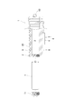
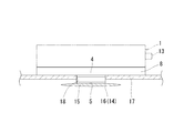
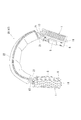
- FIG. 3 is an exploded view of a part of the cooling device unit in a longitudinal section. It is a typical longitudinal section of an embodiment which attached a heat absorption pad to a Peltier device. It is a typical top view of embodiment which attached the heat absorption pad to the Peltier device. It is a perspective view of the cap which provided the opening. It is a perspective view which shows the cap which fixed the cooling device unit. It is a perspective view which shows a headphone-shaped neck hanging member. It is a perspective view which shows the athletic shoe which provided the opening. It is a perspective view which shows the athletic shoes which fixed the cooling device unit. It is a front view of the cooling device unit for hats.
- the cooling device unit 1 includes a radiator 2 provided with a plurality of radiating fins 10, and a battery housing portion provided like a cave in the radiator 2. 3 (refer to FIG. 2), a heat radiation side Peltier surface portion 4 and a heat absorption side Peltier surface portion 5.
- the heat radiator 2, the heat radiating side Peltier surface portion 4, and the heat absorbing side Peltier surface portion 5 are integrally configured as a unit.
- the heat-radiating Peltier surface portion 4 and the heat-absorbing side Peltier surface portion 5 constitute a known Beltier element 6, and a current is passed by the voltage of the battery 7 provided in the battery housing portion 3. And the heat is released from the heat radiation side Peltier surface portion 4 through the heat radiator 2 to the outside.
- the radiator 2 is made of metal such as copper and aluminum having good thermal conductivity, and can accommodate the battery 7 in the battery accommodating portion 3.
- a small dry battery or a small storage battery can be used as the battery 7.
- a custom-made battery that can be used only for the cooling device unit 1 increases the cost of use and limits the location where it can be obtained.
- the battery accommodated in the battery accommodating portion 3 can also be used as a part of the heat dissipation material.
- the battery performance and life tend to be shortened. Therefore, there is an advantage that the battery performance is easily exhibited by appropriately raising the temperature of the dry battery.
- the radiator 2 has a configuration in which a substantially cylindrical portion 9 is formed on a base portion 8.
- a battery housing part 3 is formed by the substantially cylindrical part 9, and a plurality of radiating fins 10 erected in a direction substantially orthogonal to the cylindrical axis are formed on the peripheral wall surface.
- a lid 11 for inserting a battery is provided on one end side of the radiator 2.
- the lid portion 11 is configured to be detachable from the end portion of the substantially cylindrical portion 9 by a structure such as screwing or fitting.
- a flat switch mounting portion 12 (see FIG. 1) is provided on the other end side of the radiator 2, and a switch portion 13 is provided on the switch mounting portion 12.
- the switch unit 13 is configured so that at least the cooling function ON and the cooling function OFF can be operated.
- the switch unit 13 shown in FIGS. 1 and 2 is a push button switch, and is configured to be switched to a weakly cooled state when pressed once in the cylindrical axis direction, to a strongly cooled state when pressed twice, and to an OFF state when pressed three times. It is. That is, the degree of cooling can be set in a plurality of stages (in this case, two stages). When the Peltier element 6 is operated in a state where the cooling effect is high, the battery consumption is increased and the cooling time is shortened.
- the Peltier element 6 when the Peltier element 6 is operated in a state where the cooling effect is low, the battery is consumed and can be cooled for a long time.
- the user can select a plurality of operating conditions by operating the switch unit 13.
- the switch unit 13 may be provided not only with a push button switch but also with a dial type switch unit 13 that rotates in the circumferential direction of the cylinder as shown in FIG.
- the heat dissipation side Peltier surface portion 4 and the heat absorption side Peltier surface portion 5 are integrally attached to the base portion 8 of the radiator 2, and in the configuration shown in FIGS. 1 and 2, only the Peltier element 6 is the central portion of the base portion 8.
- the heat absorption pad 14 can be attached to the heat absorption side Peltier surface part 5 side as needed.
- 3 and 4 are diagrams showing such a configuration example.
- the heat absorbing pad 14 is constituted by a heat absorbing bag 16 in which a gel 15 (liquid having a certain degree of viscosity) having good thermal conductivity is enclosed.
- a gel 15 liquid having a certain degree of viscosity
- those generally used as a cryogen can be exemplified.
- Ingredients of the cryogen are often composed of water, a water-absorbing polymer, a preservative and the like.
- an opening 18 is provided in a part of the body wearing body 17 such as a hat, a helmet, shoes, clothes, etc., and the heat absorbing side of the Peltier element 6 from the opening 18.
- the Peltier surface portion 5 may be exposed to the body side, and the heat absorption bag 16 having a larger area than the heat absorption side Peltier surface portion 5 may be fixed to the exposed surface.
- the fixing method it is simple to apply an adhesive having good thermal conductivity on the exposed surface. If it is such a structure, since the heat absorption bag 16 contacts a body in an area wider than the area of the heat absorption side Peltier surface part 5, the heat of a body can be efficiently sent to the heat radiator 2 side.
- the gel 15 is enclosed in the endothermic bag 16, it can be deformed corresponding to the shape of the body, and there is an advantage that adhesion is improved.
- the body mounting body 17 and the base unit 8 are fixed so that a cloth material (not shown) attached to the base unit 8 is sewn to the body mounting body 17 or is firmly attached by a fixing method such as adhesion. To do.
- the second embodiment is an embodiment in which the cooling device unit according to the present invention is attached to a cap as shown in FIGS.
- the feature of the second embodiment is that, first of all, as shown in FIG. 5, an opening 18 is provided at a predetermined position of the cap 19, and the heat absorption side Peltier surface portion 5 (not shown) is connected to the head through the opening 18. It is in the point comprised so that it might be exposed to the side.
- a heat absorbing pad 14 or a heat absorbing bag 16 filled with gel as shown in FIG. 3 is attached to the exposed surface of the heat absorbing side Peltier surface portion 5 and arranged so as to contact the head.
- the second feature according to the present embodiment is that the base portion 8 of the radiator 2 is curved so as to match the curvature of the cap 19 provided with the opening 18.
- the form of the curve is set as appropriate in accordance with the case where the cooling device unit 1 is arranged around the head or the case where the cooling device unit 1 is arranged around the head.
- the base portion 8 is curved into a shape along the curved surface constituting the cap 19, and the battery housing portion 3 is formed on the curved base portion 8.
- the third embodiment is characterized in that a body-mounted body 17 is configured by a headphone-shaped neck member 20.
- an elastic member 21 made of metal, synthetic resin, or the like is formed in a U shape, and the cooling device units 1, 1 are disposed at both ends of the elastic member 21 with the heat absorption side Peltier surface portions 5, 5 facing inward. It is the installed configuration.
- the elastic member 21 not only a configuration using a plurality of elastic members 21, but also a flat elastic member 21 formed in a U shape can be adopted.
- the elastic member 21 is urged in the elastic direction so that the neck can be pinched, and the heat absorption side Peltier surface portions 5 and 5 of the pair of cooling device units 1 and 1 at both ends are positioned around the neck. The part is cooled by cooling.
- the elastic member 21 located at the rear of the neck is provided with a neck rear abutment 22 as a buffer for improving the contact feeling to the neck, and the neck rear abutment 22 is provided so as to cover the elastic member 21.
- a configuration in which an endothermic pad is attached to the endothermic Peltier surface portion 5 can also be employed.
- almost the whole neck hanging member 20 is wrapped with an exterior member (not shown) such as a cloth or a woven material, the heat absorption side Peltier surface portion 5 is exposed from an opening provided in the exterior member, and the heat dissipator is used as the exterior member. It is also possible to adopt a configuration that exposes from the outside.
- the fourth embodiment is an embodiment in which the cooling device unit according to the present invention is applied to various shoes.
- This embodiment employs athletic shoes 23 as shoes.
- an opening 18 is provided at a predetermined position of the outer surface member 24 constituting the athletic shoe 23, and the cooling device unit 1 according to the present invention is fixed to the opening 18 as shown in FIG. Yes.
- known materials such as camber ground, leather, synthetic leather, and polyvinyl chloride can be used.
- the opening 18 is provided in the tongue piece portion 26 provided on the lower side of the lace portion 25 of the athletic shoe 23, and the cooling device unit 1 is also fixed to the tongue piece portion 26.
- the cooling device unit 1 is fixed from the upper part of the cooling device unit 1 with a fastening string 27, so that the cooling device unit 1 is not easily dropped from the tongue piece portion 26 even if intense exercise is performed. . If exercise is performed, the temperature in the athletic shoe 23 is increased, but a cooling effect including a psychological effect can be obtained by cooling the instep portion with which the tongue piece portion 26 contacts.
- the structure which attaches the cooling device unit 1 not only to the tongue piece part 26 located in the upper part of the athletic shoes 23 but to the outer surface members 24, such as a toe part of the athletic shoes 23, is also employable.
- the fifth embodiment has a configuration in which heat radiating plates 28 are arranged side by side so as to pile up bars at a predetermined interval d in the region L to be cooled.
- the interval d of the heat sink 28 is often set to a constant value in the entire region L, but the heat dissipating plate 28 has more heat, particularly at locations where heat is generated, by reducing the arrangement interval. You may comprise so that it may absorb.
- the heat radiating plate 28 is made of a light metal such as aluminum having a relatively high thermal conductivity in a thin plate having a thickness of 0.2 to 0.8 mm so as not to feel the weight. Further, the number of the heat radiating plates 28 is preferably about 10 to 50.
- the stacked form of the heat dissipation plates 28 is preferably substantially orthogonal to the body surface, but may be stacked with an angle of 90 ° or less.
- the stacking interval d is preferably about 2 mm to 10 mm.
- a film body 29 indicated by a one-dot chain line is composed of a fiber face material, a film formed of a predetermined material, and the like.
- a heat exhaust passage that naturally (or forcibly) sends wind from the top to the bottom can be configured.
- the heat radiating body 28 can be seen from the outside.
- the body-mounted body 17 that emphasizes the fun of design when the heat radiating plate 28 can be seen from the outside can be configured.
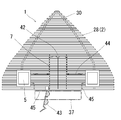
- the heat sink 28 on the base end side is attached with a battery housing portion 3 formed by a notch, an opening, and the like, and a heat conductive member 30 that thermally integrates each heat sink 28. It has the part 31 and the notch part 32 for ventilation which escapes the heat
- the battery accommodating portion 3 is configured by forming an opening having a shape in which two circles for accommodating a pair of dry cells are connected. When the number of batteries 7 is not two but three or four, the openings and notches are appropriately configured to accommodate the batteries.
- the attachment portion 31 is formed with an opening 33 through which the heat conducting member 30 passes.
- Each radiator plate 28 is formed to be curved so as to correspond to the surface shape of the region L to be cooled.
- each radiator plate 28 is curved along the curved surface of the head. Is formed.
- the heat radiating plate 28 shown in FIG. 12 is configured by extracting a part of the heat radiating plate 28 shown in FIG. 10, and does not show all the heat radiating plates 28.
- a plus side electrode portion 42 and a minus side electrode portion 43 are provided corresponding to the battery housing portion 3, and the heat radiation side Peltier surface portion 4 and the heat absorption side Peltier surface portion 5 are provided by wirings 44 and 45. Connected to.
- FIG. 13 a configuration in which an intake port 35 is provided at a lower position near the eaves 34 of the cap 19 and an exhaust port 36 is provided at an upper position near the top of the cap 19 can be adopted.
- the exhaust heat passage 40 extending from the intake port 35 to the exhaust port 36 can be formed.
- the configuration shown in FIG. 13 shows a configuration in which a pair of slit-shaped intake ports 35 are provided near the eaves 34 and a pair of slit-shaped exhaust ports 36 are provided at the upper position of the cap. With this configuration, the air warmed by the head rises upward mainly through the ventilation notch 32 (see FIG.
- the shapes of the exhaust port 35 and the exhaust port 36 are not limited to the slit shape, and various shapes can be adopted.
- the heat in the head and the hat 19 is absorbed from the heat-absorbing side Peltier surface portion 5 and can be conducted to all the heat radiating plates 28 by the heat conducting member 30 arranged on the heat-radiating side Peltier surface portion 4 side. Therefore, heat dissipation can be improved.
- the heat conductive member 30 is comprised by the pipe
- a portion indicated by a one-dot chain line indicates a fan 37 provided as necessary.
- the fan 37 generates forced air on the heat radiating plate 28, and heat can be promoted by sucking air from the intake port 35 and flowing air to the exhaust port 36.
- the fan 37 is driven by a fan power supply (not shown) housed in the heat radiating plate 28.
- the fan 37 is disposed at a preferred position of the exhaust heat passage 40.
- the fan 13 can be used to drive the fan 37 by attaching a sheet-like solar cell 38 as shown by the alternate long and short dash line to the eaves 34 of the cap 19 and supplying or accumulating power to the fan power supply. It is also possible to adopt a storage battery configuration in which the electric power generated by the solar battery 38 is used as the electric power for driving the Peltier element, if necessary.
- the cooling device unit having the above configuration will be briefly described.
- the Peltier element is driven according to the strength of the operated switch (for example, strong cooling, weak cooling, etc.), as shown in FIG.
- heat is absorbed from the heat absorption side Peltier surface portion 5 provided on the head side of the hat, and is radiated from the heat radiation side Peltier surface portion 4.
- the heat conduction member 30 is thermally connected to the heat radiation side Peltier surface portion 4 side, heat is conducted from the heat conduction member 3 to each heat radiation plate 28, and heat is radiated from each heat radiation plate 28.
- thermally connect includes a case where the heat-radiating side Peltier surface portion 4 side and the heat conducting member 30 are in direct contact and a case where heat is conducted through a space or an interposed member.
- a plate surface portion having a size that covers the heat radiation side Peltier surface portion 4 may be provided on the heat conduction member 30 so that the heat of the heat radiation side Peltier surface portion 4 is well transmitted to the heat conduction member 30.
- the radiated air in the cap 19 naturally moves upward through the exhaust heat passage 40 and is exhausted as exhaust air 41.
- the intake air 39 is sucked from the intake port 35, and as a result, a flow of air that exhausts heat from the heat radiating plate 28 can be created.
- the fan 37 By providing the fan 37, this air flow is further promoted, and the heat in the cap 19 can be released to the outside powerfully.
- the heat radiating plate 28 is formed by punching a metal plate, there is an advantage that it is not necessary to use a mold or the like, and the manufacturing cost can be reduced.
- the battery accommodating part 3 is also comprised by die cutting in the heat sink 28, it is cheaper than comprising with another component.
- the housing space for the battery 7 is provided in the heat radiating plate 28, the space is saved and the retainability of the battery 7 can be improved.
- FIG. 14 A sixth embodiment of the present invention will be described with reference to FIG. Also in the sixth embodiment, a description will be given assuming a hat (not shown in FIG. 14) as the body wearing body 17.
- the first feature of this embodiment is that the heat conducting member 30 is formed in a ring shape, and the heat radiating plate 28 supported by the heat conducting member 30 formed in the ring shape is also arranged in a ring shape. That is, the space 47 is formed inside the heat dissipation plate 28 formed in a ring shape.
- the second feature is that a battery housing part 3 for housing the battery 7 is formed in a ring-shaped base side heat sink 51 (one form of the heat sink 28) located on the base end side as viewed from the Peltier surface.
- This 7th Embodiment shows a suitable structure when the structure of this invention is applied to a helmet.
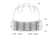
- the helmet 52 shown in FIG. 16 to FIG. 17 is provided so that a large number of heat dissipation plates 28 are arranged on the eaves 53, and heat from the heat dissipation side Peltier surface (not shown in FIG. 15) by the heat conducting member 30. Is conducted to the heat radiating plate 28 via the heat conducting member 30 to radiate heat.
- the heat conduction member 30 is thermally connected to a plurality of heat radiation side Peltier surface portions provided inside the helmet 52. For example, in the configuration shown in FIG.
- the pair of heat conducting members 30 are pulled out from the left and right direction 61 of the helmet 52, bent upward from the left and right side surfaces 53 a of the eaves 53, and connected to the heat dissipation plate 28 on the eaves 53. It is composed.
- the heat conducting member 30 is composed of a flexible heat pipe or the like, and is configured so that it can be appropriately bent according to the existing helmet 52. In other words, the drawer configuration in which the heat conducting member 30 is guided onto the eaves 53 can be appropriately changed in its drawer position and bent shape depending on the shape of the helmet 52 and the like. Although not shown in the figure, it is preferable to cover the heat conducting member 30 at a location that hits the head or a portion that touches the hand with a heat insulating tube.
- the mounting surface material 54 made of a fiber material or a synthetic resin material provided with the Peltier element and the heat conducting member 30 is used as the head holder 55 in the helmet 52. It is possible to adopt a configuration that can be attached detachably with a hook-and-loop fastener. Examples of the hook-and-loop fastener include Velcro (registered trademark). Further, in order to fix the heat conducting member 30 to the helmet 52, a method of attaching the holding clip 56 corresponding to the thickness of each part of the helmet to the heat conducting member 30 in advance can be adopted. As a method of attaching the heat sink 28 on the eaves 53, a configuration in which a suction cup 57 (see FIG.
- the battery unit for driving the Peltier element is configured to be fixed at a predetermined position in the helmet or a predetermined position of the operator's body such as a shoulder.
- the heat conducting member 30 is made of a material that can be bent, and the attachment member 62 such as the detachable mounting surface material 54, the suction cup 57, the holding clip 56, and / or the fixing clip 58 is used as a set for the helmet.
- the helmet 52 is preferably a dedicated product as a heat countermeasure helmet. However, it is not excluded that the helmet used by the worker is attached only to a hot work place or a hot period such as summer. On the other hand, it is of course possible to manufacture it as a heat countermeasure helmet at the factory manufacturing stage.
- the eighth embodiment of the present invention will be described with reference to FIG.
- This eighth embodiment also shows a preferred configuration when the configuration of the present invention is applied to a helmet.
- the helmet 52 of this embodiment is different from the above embodiment in that the radiator plate 28 is fixed to the top of the helmet 52. Further, if necessary, a lightweight upper cover 59 can be provided above the heat radiating plate 28 to enhance the design of the helmet 52.
- the upper cover plate 59 can also function as a wind guide cover. Another difference is that a plurality of holes 60 having a diameter through which the heat conducting member 30 passes are formed at places where the strength and safety of the helmet 52 are not affected at all, and heat conduction in the helmet 52 is conducted from the holes 60.
- FIG. 18 a structure in which the upper cover 59 and the heat radiating plate 28 are disassembled is illustrated on the upper part of the helmet 52 together with the completed helmet 52.
- the helmet 52 provided with the holes 60 at the manufacturing stage before shipment.
- the configuration in which the hole 60 is provided can be similarly adopted in the configuration in which the heat dissipation plate 28 is provided on the eaves 53.
- the present invention can be variously modified within the scope of the present invention other than the above embodiment.
- the heat dissipating fins formed on the outer wall of the heat dissipating body are configured with relatively small ones.
- a configuration in which a predetermined metal is used to project outwardly like a butterfly wing is employed.
- the shape and configuration of the heat dissipating fin according to the present specification are not particularly limited as long as the heat dissipating fin is a protrusion of the heat dissipating body that can increase the contact area of the external air.
- the battery has been described as having a cylindrical shape, but the overall shape of the radiator is changed in accordance with the shape of the battery employed in the present invention. Even in this case, it is preferable that a plurality of heat radiating fins are erected toward the outside of the heat radiating body in which the battery housing portion is formed.
- the number of the cooling device units according to the present invention attached to the body-worn body and the size of the cooling device unit vary depending on the required cooling range. Generally, when a large number of cooling unit units are installed, the total weight of the cooling unit increases. Similarly, when a large cooling device unit is attached, the weight of the body-mounted body increases. Accordingly, the number and size of the cooling device units are appropriately set in consideration of the effect of cooling and the disadvantage caused by the weight increase.
- the heat dissipation side Peltier surface portion and the heat absorption side Peltier surface portion are illustrated as having a rectangular shape, but various forms such as a circle and an ellipse may be adopted as necessary. is there.
- a cooling device unit for a body-worn body can also be configured by fixing a radiator to the outer wall surface of the body-worn body. With this configuration, the cooling device unit can be similarly adopted even for body-worn bodies of various shapes and configurations such as clothes.
- the configuration of the heat dissipation plate in the fifth embodiment and the sixth embodiment can be applied to a body-worn body other than a hat by appropriately changing the shape.
- the heat absorption side Peltier surface portion may be arranged discretely so as to cover a wide range of a body-worn body such as a hat so as to feel cool in a wide range.
- the configuration of the heat absorbing pad 14 described in FIGS. 3 to 4 can also be applied.
- Annular base end side heat radiating plate (one form of radiating plate 28) 52 ... Helmet (body wearing body 17) 53 ... eaves 54 ... mounting surface material (an example of a detachable mounting member 62) 56.
- Holding clip (an example of a detachable mounting member 62) 57 ...
- Suction cup (an example of a detachable mounting member 62) 58...
- Clip for fixing (an example of a detachable mounting member 62) 60 ... Hole 62 ... Mounting member L ... Area to be cooled
Landscapes
- Health & Medical Sciences (AREA)
- Vascular Medicine (AREA)
- Thermal Sciences (AREA)
- Engineering & Computer Science (AREA)
- Biomedical Technology (AREA)
- Heart & Thoracic Surgery (AREA)
- Physics & Mathematics (AREA)
- Life Sciences & Earth Sciences (AREA)
- Animal Behavior & Ethology (AREA)
- General Health & Medical Sciences (AREA)
- Public Health (AREA)
- Veterinary Medicine (AREA)
- Helmets And Other Head Coverings (AREA)
- Thermotherapy And Cooling Therapy Devices (AREA)
Priority Applications (1)
| Application Number | Priority Date | Filing Date | Title |
|---|---|---|---|
| JP2013556197A JP5706008B2 (ja) | 2012-02-04 | 2012-10-12 | 身体装着体用の冷却装置ユニット |
Applications Claiming Priority (2)
| Application Number | Priority Date | Filing Date | Title |
|---|---|---|---|
| JP2012022581 | 2012-02-04 | ||
| JP2012-022581 | 2012-09-19 |
Publications (1)
| Publication Number | Publication Date |
|---|---|
| WO2013114680A1 true WO2013114680A1 (fr) | 2013-08-08 |
Family
ID=48904746
Family Applications (1)
| Application Number | Title | Priority Date | Filing Date |
|---|---|---|---|
| PCT/JP2012/076391 Ceased WO2013114680A1 (fr) | 2012-02-04 | 2012-10-12 | Unité de dispositif de refroidissement pour un élément porté sur le corps |
Country Status (2)
| Country | Link |
|---|---|
| JP (1) | JP5706008B2 (fr) |
| WO (1) | WO2013114680A1 (fr) |
Cited By (4)
| Publication number | Priority date | Publication date | Assignee | Title |
|---|---|---|---|---|
| EP3089713A4 (fr) * | 2014-01-02 | 2017-08-16 | Schawbel Technologies LLC | Dispositif de refroidissement et de chauffage du cou |
| JP2018529032A (ja) * | 2015-09-21 | 2018-10-04 | ストライカー・コーポレイション | 冷却ストリップを備えた個人保護システム |
| CZ307567B6 (cs) * | 2016-12-09 | 2018-12-12 | Vysoká Škola Báňská-Technická Univerzita Ostrava | Univerzální zařízení pro lokální aplikaci hypotermie na oblasti zejména kolenního kloubu |
| JP2020096719A (ja) * | 2018-12-18 | 2020-06-25 | マクセルホールディングス株式会社 | 小型電気機器 |
Families Citing this family (1)
| Publication number | Priority date | Publication date | Assignee | Title |
|---|---|---|---|---|
| CN111194953A (zh) * | 2020-02-24 | 2020-05-26 | 五邑大学 | 一种高温杀病毒口罩 |
Citations (5)
| Publication number | Priority date | Publication date | Assignee | Title |
|---|---|---|---|---|
| JPS55112518U (fr) * | 1979-01-31 | 1980-08-07 | ||
| JPS61155331U (fr) * | 1985-03-19 | 1986-09-26 | ||
| JPH03121067A (ja) * | 1989-10-04 | 1991-05-23 | Kineshio:Kk | 冷却帽子並びに熱交換器 |
| JPH10258079A (ja) * | 1997-03-21 | 1998-09-29 | Sanyo Mach Works Ltd | 保温・保冷具 |
| JP2010082427A (ja) * | 2008-09-03 | 2010-04-15 | Sanesu:Kk | ペルチェ素子を用いた身体冷暖房装置 |
-
2012
- 2012-10-12 WO PCT/JP2012/076391 patent/WO2013114680A1/fr not_active Ceased
- 2012-10-12 JP JP2013556197A patent/JP5706008B2/ja not_active Expired - Fee Related
Patent Citations (5)
| Publication number | Priority date | Publication date | Assignee | Title |
|---|---|---|---|---|
| JPS55112518U (fr) * | 1979-01-31 | 1980-08-07 | ||
| JPS61155331U (fr) * | 1985-03-19 | 1986-09-26 | ||
| JPH03121067A (ja) * | 1989-10-04 | 1991-05-23 | Kineshio:Kk | 冷却帽子並びに熱交換器 |
| JPH10258079A (ja) * | 1997-03-21 | 1998-09-29 | Sanyo Mach Works Ltd | 保温・保冷具 |
| JP2010082427A (ja) * | 2008-09-03 | 2010-04-15 | Sanesu:Kk | ペルチェ素子を用いた身体冷暖房装置 |
Cited By (6)
| Publication number | Priority date | Publication date | Assignee | Title |
|---|---|---|---|---|
| EP3089713A4 (fr) * | 2014-01-02 | 2017-08-16 | Schawbel Technologies LLC | Dispositif de refroidissement et de chauffage du cou |
| JP2018529032A (ja) * | 2015-09-21 | 2018-10-04 | ストライカー・コーポレイション | 冷却ストリップを備えた個人保護システム |
| US10973275B2 (en) | 2015-09-21 | 2021-04-13 | Stryker Corporation | Personal protection system with a cooling strip that is both removable and that is compliant relative to the skin |
| CZ307567B6 (cs) * | 2016-12-09 | 2018-12-12 | Vysoká Škola Báňská-Technická Univerzita Ostrava | Univerzální zařízení pro lokální aplikaci hypotermie na oblasti zejména kolenního kloubu |
| JP2020096719A (ja) * | 2018-12-18 | 2020-06-25 | マクセルホールディングス株式会社 | 小型電気機器 |
| JP7143204B2 (ja) | 2018-12-18 | 2022-09-28 | マクセル株式会社 | 小型電気機器 |
Also Published As
| Publication number | Publication date |
|---|---|
| JP5706008B2 (ja) | 2015-04-22 |
| JPWO2013114680A1 (ja) | 2015-05-11 |
Similar Documents
| Publication | Publication Date | Title |
|---|---|---|
| JP5706008B2 (ja) | 身体装着体用の冷却装置ユニット | |
| US7921473B1 (en) | Head cooling apparatus | |
| US8087254B2 (en) | Personal heat control device and method | |
| JP6869352B2 (ja) | 電子降温装置 | |
| US10765166B2 (en) | Helmet with mechanism for cooling | |
| KR20210079040A (ko) | 냉온감 조끼 | |
| KR101040962B1 (ko) | 다기능 장갑 | |
| JP2009097106A (ja) | 空冷服 | |
| KR102533422B1 (ko) | 쿨링 넥밴드용 쿨링패드 | |
| CN209807220U (zh) | 用于帽子的调温装置 | |
| ES2641890T3 (es) | Instalación de control de temperatura para regular la temperatura en un espacio y armario de distribución con una instalación de control de temperatura de este tipo | |
| KR100813282B1 (ko) | 냉열수단이 구비된 작업화 | |
| CN207783407U (zh) | 一种头戴式显示设备 | |
| JP7564527B1 (ja) | 衣服用の冷却装置 | |
| CN213098699U (zh) | 一种头戴式降温仪 | |
| KR20150003535A (ko) | 냉방 깔창 | |
| JP3142672U (ja) | ヘルメット用冷却ユニット | |
| CN213464100U (zh) | 一种背包辅助散热装置 | |
| JP7616613B2 (ja) | ファン装置とファン装置用ウェアの組合せ | |
| US20110052434A1 (en) | Switch and Motor-Cooling Device for an Electric Fan | |
| CN223554479U (zh) | 冷气背包 | |
| CN218817106U (zh) | 腰戴式风扇装置 | |
| KR20210000100U (ko) | 펠티어 소자를 이용한 목 냉온 장치 | |
| CN224166396U (zh) | 皮肤护理装置及护理系统 | |
| KR101742601B1 (ko) | 냉난방 기능을 가지는 신발용 깔창 |
Legal Events
| Date | Code | Title | Description |
|---|---|---|---|
| 121 | Ep: the epo has been informed by wipo that ep was designated in this application |
Ref document number: 12867618 Country of ref document: EP Kind code of ref document: A1 |
|
| ENP | Entry into the national phase |
Ref document number: 2013556197 Country of ref document: JP Kind code of ref document: A |
|
| NENP | Non-entry into the national phase |
Ref country code: DE |
|
| 122 | Ep: pct application non-entry in european phase |
Ref document number: 12867618 Country of ref document: EP Kind code of ref document: A1 |