WO2013114770A1 - マルチコア光ファイバテープ - Google Patents
マルチコア光ファイバテープ Download PDFInfo
- Publication number
- WO2013114770A1 WO2013114770A1 PCT/JP2012/083637 JP2012083637W WO2013114770A1 WO 2013114770 A1 WO2013114770 A1 WO 2013114770A1 JP 2012083637 W JP2012083637 W JP 2012083637W WO 2013114770 A1 WO2013114770 A1 WO 2013114770A1
- Authority
- WO
- WIPO (PCT)
- Prior art keywords
- core optical
- optical fiber
- core
- fiber tape
- optical fibers
- Prior art date
- Legal status (The legal status is an assumption and is not a legal conclusion. Google has not performed a legal analysis and makes no representation as to the accuracy of the status listed.)
- Ceased
Links
Images





Classifications
-
- G—PHYSICS
- G02—OPTICS
- G02B—OPTICAL ELEMENTS, SYSTEMS OR APPARATUS
- G02B6/00—Light guides; Structural details of arrangements comprising light guides and other optical elements, e.g. couplings
- G02B6/44—Mechanical structures for providing tensile strength and external protection for fibres, e.g. optical transmission cables
- G02B6/4401—Optical cables
- G02B6/4403—Optical cables with ribbon structure
-
- G—PHYSICS
- G02—OPTICS
- G02B—OPTICAL ELEMENTS, SYSTEMS OR APPARATUS
- G02B6/00—Light guides; Structural details of arrangements comprising light guides and other optical elements, e.g. couplings
- G02B6/02—Optical fibres with cladding with or without a coating
- G02B6/02033—Core or cladding made from organic material, e.g. polymeric material
-
- G—PHYSICS
- G02—OPTICS
- G02B—OPTICAL ELEMENTS, SYSTEMS OR APPARATUS
- G02B6/00—Light guides; Structural details of arrangements comprising light guides and other optical elements, e.g. couplings
- G02B6/04—Light guides; Structural details of arrangements comprising light guides and other optical elements, e.g. couplings formed by bundles of fibres
- G02B6/06—Light guides; Structural details of arrangements comprising light guides and other optical elements, e.g. couplings formed by bundles of fibres the relative position of the fibres being the same at both ends, e.g. for transporting images
- G02B6/08—Light guides; Structural details of arrangements comprising light guides and other optical elements, e.g. couplings formed by bundles of fibres the relative position of the fibres being the same at both ends, e.g. for transporting images with fibre bundle in form of plate
-
- G—PHYSICS
- G02—OPTICS
- G02B—OPTICAL ELEMENTS, SYSTEMS OR APPARATUS
- G02B6/00—Light guides; Structural details of arrangements comprising light guides and other optical elements, e.g. couplings
- G02B6/44—Mechanical structures for providing tensile strength and external protection for fibres, e.g. optical transmission cables
- G02B6/4479—Manufacturing methods of optical cables
- G02B6/448—Ribbon cables
-
- G—PHYSICS
- G02—OPTICS
- G02B—OPTICAL ELEMENTS, SYSTEMS OR APPARATUS
- G02B6/00—Light guides; Structural details of arrangements comprising light guides and other optical elements, e.g. couplings
- G02B6/02—Optical fibres with cladding with or without a coating
- G02B6/02042—Multicore optical fibres
Definitions
- the present invention relates to a multi-core optical fiber tape.
- An optical fiber tape is known in which a plurality of single-core optical fibers arranged in parallel are collectively covered with a common resin. Such an optical fiber tape can transmit a large amount of information and is easy to handle.
- a multi-core optical fiber in which a plurality of cores, which are high refractive index portions extending in the fiber axis direction, are covered with a common cladding. If a plurality of multi-core optical fibers arranged in parallel are collectively covered with a common resin, a multi-core optical fiber tape can be manufactured. Such a multi-core optical fiber tape is expected to be capable of transmitting a larger amount of information.
- An object of the present invention is to provide a multi-core optical fiber tape that can be easily optically connected to other optical components, and to provide a method capable of easily manufacturing such a multi-core optical fiber tape. With the goal.
- a multi-core optical fiber tape including a plurality of multi-core optical fibers arranged in parallel and a common resin that collectively coats the plurality of multi-core optical fibers.
- Each multi-core optical fiber includes a plurality of cores that are a plurality of high refractive index portions extending in the axial direction, a common cladding that covers the plurality of cores, and a fiber coating that covers the cladding.
- the core arrangement direction that is the arrangement direction of the plurality of cores of each of the plurality of multi-core optical fibers is parallel to the fiber arrangement direction that is the arrangement direction of the plurality of multi-core optical fibers or It is vertical.
- the core arrangement direction of each of the multi-core optical fibers may be parallel to the fiber arrangement direction at least at both ends.
- the angle between the direction parallel to or perpendicular to the fiber array direction and the core array direction may be 2.3 ⁇ 40 / X (°) or less.
- a connector may be provided at least at one end.
- the method for producing a multi-core optical fiber tape of the present invention is a method for producing the multi-core optical fiber tape of the present invention.
- the first aspect after coating a plurality of multi-core optical fibers with a common resin, Adjusting the orientation of each of the multi-core optical fibers while observing each end face on the surface.
- a plurality of multi-core optical fibers each having a difference between a major axis and a minor axis of a coated cross section or a clad cross section of 1 ⁇ m or more are used, and the orientations of these major axes and minor axes are referred to. Adjusting the orientation of each of the plurality of multi-core optical fibers.
- the third aspect includes providing a fiber curl having a radius of curvature of 4 m or less to each of the plurality of multi-core optical fibers, and adjusting the orientation of each of the plurality of multi-core optical fibers with reference to the orientation of these fiber curls.
- the fiber curl may be imparted by providing a stress imparting portion inside the clad in each of the multiple multi-core optical fibers.
- Each of the (a) region, (b) region, and (c) region is a cross-sectional view showing a configuration example of a multi-core optical fiber.
- Each of the (a) region and (b) region is a cross-sectional view showing a configuration example of a multi-core optical fiber.
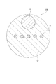
- FIG. 1A, FIG. 1B, and FIG. 1C are cross-sectional views each showing a configuration example of a multi-core optical fiber.
- the cores 11 that are seven high refractive index portions extending in the fiber axis direction are sequentially covered with the common cladding 12 and the fiber coating 13, and in cross section
- the other six cores 11 are arranged at equal intervals on the circumference of one circle centered on one core 11.
- the cores 11 that are five high refractive index portions extending in the fiber axis direction are sequentially covered with the common cladding 12 and the fiber coating 13, and in cross section Five cores 11 are arranged at equal intervals in one row.
- each of the cores 11 and the clad 12 is made of quartz glass.
- the refractive index of each core 11 is higher than the refractive index of the clad 12, and each core 11 can guide light.
- the multi-core optical fiber tape of the present invention includes such a multi-core optical fiber.
- the multi-core optical fiber tape of this invention may be comprised including the multi-core optical fiber which has another structure regarding a core number, a core arrangement
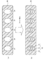
- FIG. 2 is a cross-sectional view showing a multi-core optical fiber tape 2 of a comparative example.
- the multi-core optical fiber tape 2 five multi-core optical fibers 10 arranged in parallel are collectively covered with a common resin 20, and the core arrangement directions of the multi-core optical fibers 10 are various. Therefore, the multi-core optical fiber tape 2 is difficult to optically connect with other optical components, or has a large connection loss during the optical connection.
- FIG. 3 is a cross-sectional view showing the multi-core optical fiber tape 1 according to the embodiment of the present invention.
- the multi-core optical fiber tape 1 five multi-core optical fibers 10 arranged in parallel are collectively covered with a common resin 20, and the core arrangement direction of each multi-core optical fiber 10 is parallel to the fiber arrangement direction. . Therefore, the multi-core optical fiber tape 1 is easy to optically connect with other optical components, and the connection loss at the time of the optical connection is small.
- the multi-core optical fiber 10 may have a configuration as shown in FIGS. 1A to 1C, or may have another configuration.
- the “core arrangement direction” is a direction in which the most cores are arranged in a line in the cross section of the multi-core optical fiber 10. In FIG. 1B and FIG. 1C, the left-right direction is the “core arrangement direction”. In the region of FIG. 1A, there are three “core arrangement directions”.
- the core arrangement direction of each multi-core optical fiber 10 may be “perpendicular to the fiber arrangement direction” instead of “parallel to the fiber arrangement direction”.
- the core arrangement direction of each multi-core optical fiber 10 may be parallel or perpendicular to the fiber arrangement direction at both ends. In an intermediate portion other than both ends of the multi-core optical fiber tape 1, the core arrangement direction of each multi-core optical fiber 10 may not be parallel or perpendicular to the fiber arrangement direction.
- the angle deviation is 2.3 ⁇ 40 / X (°) or less.
- the angle deviation between the direction parallel to or perpendicular to the fiber arrangement direction and the core arrangement direction is 2.3 ° or less.
- the multi-core optical fiber tape 1 is provided with a connector at least at one end. In this case, the optical connection work with other optical components becomes easy.
- FIG. 11 is a conceptual diagram showing an example of a method for manufacturing the multi-core optical fiber tape 1.
- a plurality of multi-core optical fibers 10 are arranged in parallel and then collectively covered with a common resin 20 to form an assembly 3 ((a) region).
- the assembly 3 is cut to a desired length, the common resin 20 at one end thereof is removed, and the multiple multi-core optical fibers 10 are exposed (region (b)).
- the orientation (rotational orientation around the central axis) of each multi-core optical fiber 10 is adjusted and fixed ((c region)).
- the common resin 20 is removed, the multiple multi-core optical fibers 10 are exposed, and the orientation of each multi-core optical fiber 10 is adjusted and fixed while observing the exposed end faces of the multi-core optical fibers 10. To do.
- the multi-core optical fiber tape 1 in which the core arrangement direction of each multi-core optical fiber 10 is parallel or perpendicular to the fiber arrangement direction at least at both ends can be manufactured.
- the multi-core optical fiber tape 1 can also be manufactured as follows, for example.
- the multi-core optical fiber 10D or the multi-core optical fiber 10E having the configuration as shown in FIGS. 4A and 4B is used.
- the clad 12 has a non-circular cross-sectional shape, and a plurality of cores 11 are arranged in the minor axis direction.
- the multi-core optical fiber 10E is provided with the first coating resin layer 13A and the second coating resin layer 13B around the clad 12, the second coating resin layer 13B has a non-circular cross-sectional shape, and the minor axis direction A plurality of cores 11 are arranged in the middle.
- An optical fiber having a clad or coating resin layer having a non-circular cross-sectional shape is disclosed in JP-A-1-203246, JP-A-1-200310, and JP-A-63-208809.
- a multi-core optical fiber tape When arranging a plurality of multi-core optical fibers 10D or 10E in parallel, a multi-core optical fiber tape can be manufactured by aligning the non-circular orientation of the cross section with reference to the major axis and the minor axis of each multi-core optical fiber. it can. In order to ensure alignment of the non-circular orientations of the cross section, it is preferable that the difference between the major axis and the minor axis of the non-circle is 1 ⁇ m or more.
- the core arrangement direction may be the short axis direction, the long axis direction, or a specific direction with respect to the end axis direction or the long axis direction.
- each multi-core optical fiber 10 having a non-circular clad or coating resin layer at the tape end As shown in FIG. 5A, the cross-section of the multi-core optical fiber 10 A connector 30 having a plurality of through holes 31 having the same shape as the non-circular shape and aligned in the directions of the major axis and the minor axis is prepared, and each through hole 31 of the connector 30 as shown in FIG. What is necessary is just to insert the multi-core optical fiber 10 in the.
- a U-groove member 41 having a plurality of U-grooves is prepared as shown in FIG. 6A, and the multi-core optical fiber 10 is placed in each U-groove of the U-groove member 41 as shown in FIG. 6B.
- the U-groove member 42 may be fixed on the U-groove member 41 with the multi-core optical fiber 10 interposed therebetween as shown in FIG. 6C.
- a V-groove member 51 having a plurality of V-grooves is prepared as shown in FIG. 7A, and a multi-core optical fiber is provided in each V-groove of the V-groove member 51 as shown in FIG. 7B. 10 may be arranged, and the V-groove member 52 may be fixed on the V-groove member 51 with the multi-core optical fiber 10 sandwiched between them as shown in FIG.
- each multi-core optical fiber 10 having a non-circular clad or coating resin layer may be used to align the core arrangement direction of each multi-core optical fiber 10 having a non-circular clad or coating resin layer with the entire length of the tape. That is, at the initial stage of manufacture, as shown in FIG. 8, the first guide 62 provided in the front stage of the resin coating device 63 and the second guide 65 provided in the rear stage of the resin curing device 64 are used to The non-circular orientation of the cross-section of the clad or coated resin layer of the drawn multi-core optical fiber 10 is aligned and fixed, and in this state, resin coating by the resin coating device 63 and resin curing by the resin curing device 64 are started. To do.
- each multi-core optical fiber 10 when a part of each multi-core optical fiber 10 is fixed with the collective coating resin, the second guide 65 is removed and the multi-core optical fiber tape 1 after resin curing by the resin curing device 64 is removed. Then, it is wound up by a winding bobbin 68 through a capstan 67.
- a tension of 200 gf or more is applied to each multi-core optical fiber 10 by the tension applying device 66 in order to stabilize the orientation of each multi-core optical fiber 10. It is desirable.
- a fiber curl can also be used when aligning the core arrangement direction of each multi-core optical fiber 10. That is, a multi-core optical fiber tape can be manufactured by providing a fiber curl to each of a plurality of multi-core optical fibers and adjusting the orientation of each multi-core optical fiber with reference to the orientation of these fiber curls. Fiber curl is caused by radial asymmetry of stress remaining in the optical fiber. The size of the fiber curl is generally evaluated by the radius of curvature of an arc drawn by the optical fiber from which the coating has been removed.
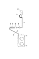
- the multi-core optical fiber 10 ⁇ / b> F can have a fiber curl by providing a stress applying portion 15 inside the cladding 12.
- fiber curl in the left-right direction is not generated due to left-right symmetry, and fiber curl is generated in the vertical direction due to vertical asymmetry, so that the core arrangement direction can be known from the direction of fiber curl.
- the stress applying portion 15 is preferably close to the outer periphery of the clad 12.
- a hole extending in the longitudinal direction of the fiber can be used for applying stress.
- fiber curls with a curvature radius of 4 m or more may occur unintentionally. Therefore, in order to distinguish unintended fiber curls from intentional fiber curls, the intentional in this embodiment
- the fiber curl preferably has a radius of curvature of 4 m or less.
- Optical fibers intentionally provided with fiber curls are disclosed in Japanese Patent Application Laid-Open Nos. 63-217309 and 1-156702.
Landscapes
- Physics & Mathematics (AREA)
- General Physics & Mathematics (AREA)
- Optics & Photonics (AREA)
- Engineering & Computer Science (AREA)
- Manufacturing & Machinery (AREA)
- Mechanical Coupling Of Light Guides (AREA)
- Optical Fibers, Optical Fiber Cores, And Optical Fiber Bundles (AREA)
- Optical Couplings Of Light Guides (AREA)
Description
本発明は、マルチコア光ファイバテープに関するものである。
並列配置された複数本のシングルコア光ファイバが共通の樹脂で一括被覆された光ファイバテープが知られている。このような光ファイバテープは、大容量の情報を伝送することができ、また、取り扱いが容易である。
また、ファイバ軸方向に延在する複数個の高屈折率部分であるコアが共通のクラッドで覆われたマルチコア光ファイバが知られている。並列配置された複数本のマルチコア光ファイバを共通の樹脂で一括被覆すればマルチコア光ファイバテープを製造することができる。このようなマルチコア光ファイバテープは更に大容量の情報を伝送することができると期待される。
本発明は、他の光学部品との光学的接続が容易なマルチコア光ファイバテープを提供することを目的し、また、このようなマルチコア光ファイバテープを容易に製造することができる方法を提供することを目的とする。
課題を解決するため、並列配置された複数本のマルチコア光ファイバと、複数本のマルチコア光ファイバを一括被覆する共通の樹脂とを含むマルチコア光ファイバテープが提供される。各々のマルチコア光ファイバは、軸方向に延在する複数個の高屈折率部分であるコアと、該複数個のコアを覆う共通のクラッドと、該クラッドとを覆うファイバコーティングとからなる。マルチコア光ファイバテープは、少なくとも両端において、複数本のマルチコア光ファイバそれぞれの複数個のコアの配列方向であるコア配列方向が、複数本のマルチコア光ファイバの配列方向であるファイバ配列方向に対し平行または垂直である。
本発明のマルチコア光ファイバテープは、少なくとも両端において、複数本のマルチコア光ファイバそれぞれのコア配列方向がファイバ配列方向に対し平行であってもよい。また、複数本のマルチコア光ファイバそれぞれにおいて、中心軸から最も遠い位置にあるコアまでの距離をX(μm)としたときに、ファイバ配列方向に対し平行または垂直な方向とコア配列方向との角度ずれが2.3×40/X(°)以下であってもよい。さらに、少なくとも片端にコネクタが設けられていてもよい。
本発明のマルチコア光ファイバテープ製造方法は、本発明のマルチコア光ファイバテープを製造する方法であって、その第一の態様では、複数本のマルチコア光ファイバを共通の樹脂で一括被覆した後、両端面において各々の端面を観察しながら複数本のマルチコア光ファイバそれぞれの方位を調整することを含む。
第二の態様では、複数本のマルチコア光ファイバそれぞれとして被覆断面またはクラッド断面の長軸と短軸との差が1μm以上であるものを用い、これらの長軸および短軸の方位を参照して複数本のマルチコア光ファイバそれぞれの方位を調整することを含む。
第三の態様では、複数本のマルチコア光ファイバそれぞれに曲率半径4m以下のファイバカールを付与し、これらのファイバカールの方位を参照して複数本のマルチコア光ファイバそれぞれの方位を調整することを含む。この場合、複数本のマルチコア光ファイバそれぞれにおいてクラッド内部に応力付与部を設けることでファイバカールを付与してもよい。
本発明によれば、他の光学部品との光学的接続が容易なマルチコア光ファイバテープを提供することができる。
以下、添付図面を参照して、本発明を実施するための形態を詳細に説明する。なお、図面の説明において同一の要素には同一の符号を付し、重複する説明を省略する。
図1(a)領域、(b)領域、(c)領域各々は、マルチコア光ファイバの構成例を示す断面図である。(a)領域に示されるマルチコア光ファイバ10Aは、ファイバ軸方向に延在する7個の高屈折率部分であるコア11が共通のクラッド12とファイバコーティング13とで順に覆われており、断面において1個のコア11を中心とする一つの円の周上に他の6個のコア11が等間隔に配置されている。(b)領域に示されるマルチコア光ファイバ10Bは、ファイバ軸方向に延在する5個の高屈折率部分であるコア11が共通のクラッド12とファイバコーティング13とで順に覆われており、断面において5個のコア11が1行に等間隔に配置されている。
(c)領域に示されるマルチコア光ファイバ10Cは、ファイバ軸方向に延在する10個の高屈折率部分であるコア11が共通のクラッド12とファイバコーティング13とで順に覆われており、断面において10個のコア11が2行5列に等間隔に配置されている。マルチコア光ファイバ10A~10Cそれぞれにおいて、各コア11およびクラッド12それぞれは石英ガラスからなり、各コア11の屈折率はクラッド12の屈折率より高く、各コア11は光を導波させることができる。
本発明のマルチコア光ファイバテープは、このようなマルチコア光ファイバを含んで構成される。或いは、本発明のマルチコア光ファイバテープは、コア数やコア配列などに関して他の構成を有するマルチコア光ファイバを含んで構成されてもよい。
図2は、比較例のマルチコア光ファイバテープ2を示す断面図である。マルチコア光ファイバテープ2では、並列配置された5本のマルチコア光ファイバ10が共通の樹脂20で一括被覆されており、各マルチコア光ファイバ10のコア配列方向が様々である。それ故、マルチコア光ファイバテープ2は、他の光学部品との光学的接続が困難であり、或いは、該光学的接続の際の接続損失が大きい。
図3は、本発明の実施形態のマルチコア光ファイバテープ1を示す断面図である。マルチコア光ファイバテープ1では、並列配置された5本のマルチコア光ファイバ10が共通の樹脂20で一括被覆されており、各マルチコア光ファイバ10のコア配列方向がファイバ配列方向に対し平行となっている。それ故、マルチコア光ファイバテープ1は、他の光学部品との光学的接続が容易であり、該光学的接続の際の接続損失が小さい。
なお、マルチコア光ファイバ10は、図1(a)領域~(c)領域に示されたような構成を有するものであってもよいし、他の構成を有するものであってもよい。「コア配列方向」は、マルチコア光ファイバ10の断面において最も多くのコアが一列に並ぶ方向とする。図1(b)領域,(c)領域では左右方向が「コア配列方向」である。図1(a)領域では、3つの「コア配列方向」が存在する。各マルチコア光ファイバ10のコア配列方向は、「ファイバ配列方向に対し平行」に替えて「ファイバ配列方向に対し垂直」となっていてもよい。
マルチコア光ファイバテープ1において、その両端において各マルチコア光ファイバ10のコア配列方向がファイバ配列方向に対し平行または垂直となっていればよい。マルチコア光ファイバテープ1の両端以外の中間部では、各マルチコア光ファイバ10のコア配列方向はファイバ配列方向に対し平行または垂直となっていなくてもよい。
マルチコア光ファイバテープ1において、各マルチコア光ファイバ10の中心軸から最も遠い位置にあるコアまでの距離をX(μm)としたときに、ファイバ配列方向に対し平行または垂直な方向とコア配列方向との角度ずれが2.3×40/X(°)以下であるのが好適である。例えば、X=40μmである場合、ファイバ配列方向に対し平行または垂直な方向とコア配列方向との角度ずれは2.3°以下であるのが好適である。このようにすることにより、角度ずれに因る接続損失を0.5dB以下とすることができる。なお、ここでは、モードフィールド径(MFD)を、ITU-T G.652のMFDノミナル値上限に相当する9.5μmとした。
また、マルチコア光ファイバテープ1において少なくとも片端にコネクタが設けられているのが好適である。この場合には他の光学部品との光学的接続作業が容易となる。
図11は、マルチコア光ファイバテープ1の製造方法の一例を示す概念図である。初めに、複数本のマルチコア光ファイバ10を並列配置した上で共通の樹脂20で一括被覆して集合体3とする((a)領域)。次いで、集合体3を所望の長さに切断し、その一方の端における共通の樹脂20を除去し、複数本のマルチコア光ファイバ10を露出させる((b)領域)。その後、露出した複数本のマルチコア光ファイバ10の端面を観察しながら各マルチコア光ファイバ10の方位(中心軸周りの回転方位)を調整し固定する((c領域))。他端においても、共通の樹脂20を除去し、複数本のマルチコア光ファイバ10を露出させ、露出した複数本のマルチコア光ファイバ10の端面を観察しながら各マルチコア光ファイバ10の方位を調整し固定する。これにより、各マルチコア光ファイバ10のコア配列方向が少なくとも両端においてファイバ配列方向に対し平行または垂直となったマルチコア光ファイバテープ1を製造することができる。
また、マルチコア光ファイバテープ1は例えば以下のようにして製造することもできる。この製造方法では、図4(a)領域、(b)領域に示されたような構成を有するマルチコア光ファイバ10Dまたはマルチコア光ファイバ10Eを用いる。マルチコア光ファイバ10Dは、クラッド12の断面形状が非円であり、短軸方向に複数個のコア11が配置されている。また、マルチコア光ファイバ10Eは、クラッド12の周囲に第1被覆樹脂層13Aおよび第2被覆樹脂層13Bが設けられていて、第2被覆樹脂層13Bの断面形状が非円であり、短軸方向に複数個のコア11が配置されている。なお、断面形状が非円であるクラッドまたは被覆樹脂層を有する光ファイバは特開平1-203246号公報、特開平1-200310号公報、特開昭63-208809号公報に開示されている。
複数本のマルチコア光ファイバ10Dまたは10Eを並列配置する際に、各マルチコア光ファイバの長軸および短軸を参照して断面の非円の方位を揃えることで、マルチコア光ファイバテープを製造することができる。断面の非円の方位を確実に揃える為には、非円の長軸と短軸との差が1μm以上であるのが好適である。なお、コア配列方向は、短軸方向であってもよいし、長軸方向であってもよいし、或いは、端軸方向または長軸方向に対して特定の方向であってもよい。
断面形状が非円であるクラッドまたは被覆樹脂層を有する各マルチコア光ファイバ10のコア配列方向をテープ端部で揃えるには、図5(a)領域に示されるようにマルチコア光ファイバ10の断面の非円形状と同じ形状を有し長軸および短軸の方向が揃った複数の貫通孔31を有するコネクタ30を用意し、図5(b)領域に示されるようにコネクタ30の各貫通孔31にマルチコア光ファイバ10を挿入すればよい。
或いは、図6(a)に示されるように複数のU溝を有するU溝部材41を用意し、図6(b)領域に示されるようにU溝部材41の各U溝にマルチコア光ファイバ10を配置し、図6(c)領域に示されるようにU溝部材41上にマルチコア光ファイバ10を挟んでU溝部材42を固定してもよい。
或いは又、図7(a)に示されるように複数のV溝を有するV溝部材51を用意し、図7(b)領域に示されるようにV溝部材51の各V溝にマルチコア光ファイバ10を配置し、図7(c)領域に示されるようにV溝部材51上にマルチコア光ファイバ10を挟んでV溝部材52を固定してもよい。
断面形状が非円であるクラッドまたは被覆樹脂層を有する各マルチコア光ファイバ10のコア配列方向をテープ全長で揃えるには、図8および図9に示されるようにしてもよい。すなわち、製造初期段階において、図8に示されるように、樹脂塗布装置63の前段に設けられた第1ガイド62および樹脂硬化装置64の後段に設けられた第2ガイド65により、サプライボビン61から繰り出されたマルチコア光ファイバ10のクラッドまたは被覆樹脂層の断面の非円の方位を揃えて一部を固定し、その状態で、樹脂塗布装置63による樹脂塗布および樹脂硬化装置64による樹脂硬化を開始する。
そして、図9に示されるように、各マルチコア光ファイバ10の一部が一括被覆樹脂で固定されたら、第2ガイド65を外して、樹脂硬化装置64による樹脂硬化後のマルチコア光ファイバテープ1を、キャプスタン67を経て巻き取りボビン68により巻き取る。なお、各マルチコア光ファイバ10の一部を固定する際は、各マルチコア光ファイバ10の方位を安定させるため、各マルチコア光ファイバ10に対して張力付与装置66により200gf以上の張力を付与しておくことが望ましい。
各マルチコア光ファイバ10のコア配列方向を揃える際にファイバカールを利用することもできる。すなわち、複数本のマルチコア光ファイバそれぞれにファイバカールを付与し、これらのファイバカールの方位を参照して各マルチコア光ファイバの方位を調整することで、マルチコア光ファイバテープを製造することができる。ファイバカールは、光ファイバに残留する応力の径方向非対称性によって生じる。ファイバカールの大きさは、被覆を除去した光ファイバが描く円弧の曲率半径で評価することが一般的である。
図10に示されるように、マルチコア光ファイバ10Fは、クラッド12内部に応力付与部15を設けることにより、ファイバカールを有することができる。マルチコア光ファイバ10Fは、左右対称性により左右方向へのファイバカールが生じず、上下非対称性により上下方向にファイバカールが生じるので、ファイバカールの向きによりコア配列方向を知ることができる。
応力付与部15には、クラッド12に対して熱膨張係数が大きく異なる材料を用いることが好ましい。また、応力付与部15は、クラッド12外周に近いことが好ましい。また、応力付与のために、ファイバ長手方向に延在する空孔を用いることもできる。なお、汎用光ファイバにおいては意図せず曲率半径4m以上のファイバカールが発生する場合があるので、意図しないファイバカールと意図的なファイバカールとを識別可能とするため、本実施形態における意図的なファイバカールは曲率半径4m以下とすることが好ましい。なお、意図的にファイバカールを与えた光ファイバは特開昭63-217309号公報、特開平1-156702号公報に開示されている。
Claims (8)
- 各々が軸方向に延在する複数個の高屈折率部分であるコアと、該複数個のコアを覆う共通のクラッドと、該クラッドとを覆うファイバコーティングとからなり、並列配置された複数本のマルチコア光ファイバと、
前記複数本のマルチコア光ファイバを一括被覆する共通の樹脂と
を含み、 少なくとも両端において、前記複数本のマルチコア光ファイバそれぞれの複数個のコアの配列方向であるコア配列方向が、前記複数本のマルチコア光ファイバの配列方向であるファイバ配列方向に対し平行または垂直であるマルチコア光ファイバテープ。 - 少なくとも両端において、前記複数本のマルチコア光ファイバそれぞれのコア配列方向がファイバ配列方向に対し平行である
請求項1に記載のマルチコア光ファイバテープ。 - 前記複数本のマルチコア光ファイバそれぞれにおいて、中心軸から最も遠い位置にあるコアまでの距離をX(μm)としたときに、ファイバ配列方向に対し平行または垂直な方向とコア配列方向との角度ずれが2.3×40/X(°)以下である
請求項1に記載のマルチコア光ファイバテープ。 - 少なくとも片端にコネクタが設けられている
請求項1に記載のマルチコア光ファイバテープ。 - 請求項1~4の何れか1項に記載のマルチコア光ファイバテープを製造する方法であって、
前記複数本のマルチコア光ファイバを前記共通の樹脂で一括被覆した後、
両端面において各々の端面を観察しながら前記複数本のマルチコア光ファイバそれぞれの方位を調整する
ことを含むマルチコア光ファイバテープを製造する方法。 - 請求項1~4の何れか1項に記載のマルチコア光ファイバテープを製造する方法であって、
前記複数本のマルチコア光ファイバそれぞれとして被覆断面またはクラッド断面の長軸と短軸との差が1μm以上であるものを用い、これらの長軸および短軸の方位を参照して前記複数本のマルチコア光ファイバそれぞれの方位を調整する
ことを含むマルチコア光ファイバテープを製造する方法。 - 請求項1~4の何れか1項に記載のマルチコア光ファイバテープを製造する方法であって、
前記複数本のマルチコア光ファイバそれぞれに曲率半径4m以下のファイバカールを付与し、
これらのファイバカールの方位を参照して前記複数本のマルチコア光ファイバそれぞれの方位を調整する
ことを含むマルチコア光ファイバテープを製造する方法。 - 前記複数本のマルチコア光ファイバそれぞれにおいてクラッド内部に応力付与部を設けることでファイバカールを付与する、
請求項7に記載のマルチコア光ファイバテープ製造方法。
Priority Applications (3)
| Application Number | Priority Date | Filing Date | Title |
|---|---|---|---|
| EP12867397.7A EP2811325A4 (en) | 2012-02-01 | 2012-12-26 | OPTICAL FIBER BAND WITH MULTIPLE SOULS |
| US14/375,533 US9453979B2 (en) | 2012-02-01 | 2012-12-26 | Multi-core optical fiber tape |
| CN201280068682.9A CN104081234B (zh) | 2012-02-01 | 2012-12-26 | 多芯光纤带 |
Applications Claiming Priority (2)
| Application Number | Priority Date | Filing Date | Title |
|---|---|---|---|
| JP2012020059A JP5910123B2 (ja) | 2012-02-01 | 2012-02-01 | マルチコア光ファイバテープの製造方法 |
| JP2012-020059 | 2012-02-01 |
Publications (1)
| Publication Number | Publication Date |
|---|---|
| WO2013114770A1 true WO2013114770A1 (ja) | 2013-08-08 |
Family
ID=48904827
Family Applications (1)
| Application Number | Title | Priority Date | Filing Date |
|---|---|---|---|
| PCT/JP2012/083637 Ceased WO2013114770A1 (ja) | 2012-02-01 | 2012-12-26 | マルチコア光ファイバテープ |
Country Status (5)
| Country | Link |
|---|---|
| US (1) | US9453979B2 (ja) |
| EP (1) | EP2811325A4 (ja) |
| JP (1) | JP5910123B2 (ja) |
| CN (1) | CN104081234B (ja) |
| WO (1) | WO2013114770A1 (ja) |
Cited By (1)
| Publication number | Priority date | Publication date | Assignee | Title |
|---|---|---|---|---|
| JP2015052704A (ja) * | 2013-09-06 | 2015-03-19 | 住友電気工業株式会社 | 光ファイバテープ心線、光ケーブル、光ファイバコード、及びテープ心線接続方法 |
Families Citing this family (11)
| Publication number | Priority date | Publication date | Assignee | Title |
|---|---|---|---|---|
| JP2015145989A (ja) * | 2014-02-04 | 2015-08-13 | 住友電気工業株式会社 | マルチコアファイバの調芯方法、コネクタの製造方法、及びリボンファイバの製造方法 |
| WO2016047658A1 (ja) * | 2014-09-24 | 2016-03-31 | 古河電気工業株式会社 | テープ心線およびテープ心線の製造方法 |
| WO2016084465A1 (ja) * | 2014-11-27 | 2016-06-02 | 古河電気工業株式会社 | 光ファイバ、光ファイバの調芯方法およびその接続構造、テープ心線およびその製造方法 |
| US9835812B2 (en) * | 2015-08-04 | 2017-12-05 | Corning Incorporated | Multi-optical fiber aggregate |
| JP7746010B2 (ja) * | 2018-03-01 | 2025-09-30 | アルコン インコーポレイティド | 安定した光干渉断層撮像のための共通経路導波路 |
| JP7156867B2 (ja) * | 2018-09-03 | 2022-10-19 | Kddi株式会社 | マルチコア光ファイバの融着のための調芯装置 |
| WO2021070241A1 (ja) * | 2019-10-08 | 2021-04-15 | 日本電信電話株式会社 | コア位置把握方法、接続方法、及び接続装置 |
| US12487413B2 (en) | 2022-10-28 | 2025-12-02 | Corning Research & Development Corporation | Core polarity invariant structured multicore fiber optic cabling system |
| DE102023102052A1 (de) | 2023-01-27 | 2024-08-01 | Fraunhofer-Gesellschaft zur Förderung der angewandten Forschung eingetragener Verein | Mehrkern-Lichtwellenleiter mit Polarisationserhaltung |
| CN120476331A (zh) * | 2023-02-14 | 2025-08-12 | 株式会社藤仓 | 多芯光纤 |
| JPWO2024224985A1 (ja) | 2023-04-24 | 2024-10-31 |
Citations (8)
| Publication number | Priority date | Publication date | Assignee | Title |
|---|---|---|---|---|
| JPS62134608A (ja) * | 1985-12-09 | 1987-06-17 | Sumitomo Electric Ind Ltd | 偏波面保存光フアイバテ−プ心線 |
| JPS63208809A (ja) | 1987-02-25 | 1988-08-30 | Sumitomo Electric Ind Ltd | 偏波保持光フアイバ |
| JPS63217309A (ja) | 1987-03-06 | 1988-09-09 | Sumitomo Electric Ind Ltd | 偏波保持光フアイバ用母材 |
| JPH01156702A (ja) | 1987-12-15 | 1989-06-20 | Sumitomo Electric Ind Ltd | 定偏波光フアイバ用母材 |
| JPH01200310A (ja) | 1988-02-05 | 1989-08-11 | Sumitomo Electric Ind Ltd | 偏平クラツド定偏波フアイバの被覆方法 |
| JPH01203246A (ja) | 1988-02-10 | 1989-08-16 | Sumitomo Electric Ind Ltd | 異方性クラッド定偏波光ファイバの被覆方法 |
| JPH10104443A (ja) * | 1996-09-26 | 1998-04-24 | Nippon Telegr & Teleph Corp <Ntt> | マルチコアファイバ |
| JP2003344731A (ja) * | 2002-05-29 | 2003-12-03 | Sumitomo Electric Ind Ltd | 偏波保持光ファイバ伝送部材およびその製造方法 |
Family Cites Families (12)
| Publication number | Priority date | Publication date | Assignee | Title |
|---|---|---|---|---|
| US4420220A (en) * | 1979-06-25 | 1983-12-13 | Bicc Public Limited Company | Optical guides |
| JP3314495B2 (ja) * | 1993-01-14 | 2002-08-12 | 住友電気工業株式会社 | テープ状光ファイバ心線 |
| US6434305B1 (en) * | 2000-02-23 | 2002-08-13 | Corning Cable Systems Llc | Optical transmission element, process as well as device for its manufacture |
| US6421487B1 (en) * | 2000-05-03 | 2002-07-16 | Alcatel | Reinforced buffered fiber optic ribbon cable |
| US6600859B2 (en) * | 2001-07-02 | 2003-07-29 | Fitel Usa Corp. | Composite modular optical fiber ribbon |
| JP3596511B2 (ja) * | 2001-10-18 | 2004-12-02 | 住友電気工業株式会社 | 光ファイバケーブル |
| US7471862B2 (en) * | 2002-12-19 | 2008-12-30 | Corning Cable Systems, Llc | Dry fiber optic cables and assemblies |
| US7415181B2 (en) * | 2005-07-29 | 2008-08-19 | Corning Cable Systems Llc | Fiber optic cables and assemblies for fiber to the subscriber applications |
| CN104169764B (zh) | 2010-03-16 | 2016-03-16 | Ofs菲特尔有限责任公司 | 用于多芯光纤电缆的单工连接器 |
| US9069143B2 (en) | 2010-03-16 | 2015-06-30 | Ofs Fitel, Llc | Multifiber connectors for multicore optical fiber cables |
| US9120693B2 (en) * | 2010-11-08 | 2015-09-01 | Corning Incorporated | Multi-core optical fiber ribbons and methods for making the same |
| US9057815B2 (en) | 2012-05-31 | 2015-06-16 | Corning Cable Systems Llc | Angular alignment of optical fibers for fiber optic ribbon cables, and related methods |
-
2012
- 2012-02-01 JP JP2012020059A patent/JP5910123B2/ja active Active
- 2012-12-26 EP EP12867397.7A patent/EP2811325A4/en not_active Withdrawn
- 2012-12-26 WO PCT/JP2012/083637 patent/WO2013114770A1/ja not_active Ceased
- 2012-12-26 US US14/375,533 patent/US9453979B2/en not_active Expired - Fee Related
- 2012-12-26 CN CN201280068682.9A patent/CN104081234B/zh active Active
Patent Citations (8)
| Publication number | Priority date | Publication date | Assignee | Title |
|---|---|---|---|---|
| JPS62134608A (ja) * | 1985-12-09 | 1987-06-17 | Sumitomo Electric Ind Ltd | 偏波面保存光フアイバテ−プ心線 |
| JPS63208809A (ja) | 1987-02-25 | 1988-08-30 | Sumitomo Electric Ind Ltd | 偏波保持光フアイバ |
| JPS63217309A (ja) | 1987-03-06 | 1988-09-09 | Sumitomo Electric Ind Ltd | 偏波保持光フアイバ用母材 |
| JPH01156702A (ja) | 1987-12-15 | 1989-06-20 | Sumitomo Electric Ind Ltd | 定偏波光フアイバ用母材 |
| JPH01200310A (ja) | 1988-02-05 | 1989-08-11 | Sumitomo Electric Ind Ltd | 偏平クラツド定偏波フアイバの被覆方法 |
| JPH01203246A (ja) | 1988-02-10 | 1989-08-16 | Sumitomo Electric Ind Ltd | 異方性クラッド定偏波光ファイバの被覆方法 |
| JPH10104443A (ja) * | 1996-09-26 | 1998-04-24 | Nippon Telegr & Teleph Corp <Ntt> | マルチコアファイバ |
| JP2003344731A (ja) * | 2002-05-29 | 2003-12-03 | Sumitomo Electric Ind Ltd | 偏波保持光ファイバ伝送部材およびその製造方法 |
Non-Patent Citations (1)
| Title |
|---|
| See also references of EP2811325A4 * |
Cited By (1)
| Publication number | Priority date | Publication date | Assignee | Title |
|---|---|---|---|---|
| JP2015052704A (ja) * | 2013-09-06 | 2015-03-19 | 住友電気工業株式会社 | 光ファイバテープ心線、光ケーブル、光ファイバコード、及びテープ心線接続方法 |
Also Published As
| Publication number | Publication date |
|---|---|
| JP2013160800A (ja) | 2013-08-19 |
| US9453979B2 (en) | 2016-09-27 |
| US20150016791A1 (en) | 2015-01-15 |
| JP5910123B2 (ja) | 2016-04-27 |
| EP2811325A4 (en) | 2015-10-21 |
| EP2811325A1 (en) | 2014-12-10 |
| CN104081234B (zh) | 2017-03-29 |
| CN104081234A (zh) | 2014-10-01 |
Similar Documents
| Publication | Publication Date | Title |
|---|---|---|
| JP5910123B2 (ja) | マルチコア光ファイバテープの製造方法 | |
| CN102681119B (zh) | 光纤缆线以及光纤带 | |
| JP4619424B2 (ja) | 光ファイバケーブル | |
| JP5782104B2 (ja) | マルチコアファイバへの低損失でモードフィールドが整合された結合のための方法、および装置 | |
| CN103814312B (zh) | 通信用多芯光纤 | |
| CN109642999B (zh) | 光纤缆线 | |
| JP5235125B2 (ja) | 光ファイバテープ及び光ファイバケーブル | |
| EP2799920B1 (en) | Multicore optical fiber | |
| JP2015052704A (ja) | 光ファイバテープ心線、光ケーブル、光ファイバコード、及びテープ心線接続方法 | |
| US12298571B2 (en) | Optical fiber bundle structure, optical connection structure, and method of manufacturing optical fiber bundle | |
| JP2020024257A (ja) | 光ファイバテープ心線、光ファイバケーブル、および光ファイバテープ心線の融着接続方法 | |
| JP6632544B2 (ja) | 光ファイバ、光ファイバの調芯方法およびその接続構造、テープ心線の製造方法 | |
| CN103969773A (zh) | 光缆 | |
| JP2016148709A (ja) | 光ファイバユニットおよび光ケーブル | |
| US11886026B2 (en) | Optical fiber ribbon, optical fiber cable, and connector-equipped optical fiber cord | |
| US12481106B2 (en) | Optical-fiber bundle structure, optical connection structure, and method of manufacturing optical-fiber bundle structure | |
| US20240255709A1 (en) | Optical fiber bundle, optical connection structure, and method for manufacturing optical fiber bundle | |
| JP2006139209A (ja) | 光ファイバコード及び光ファイバコードと光コネクタとの接続方法 | |
| JP2023082856A (ja) | 光ファイババンドル構造、光接続構造体、及び、光ファイババンドル構造の製造方法 | |
| JP2006154448A (ja) | 光ファイバコード | |
| US20240255705A1 (en) | Method for manufacturing optical fiber bundle, optical fiber bundle, optical connection structure, and determination method | |
| JPH06230242A (ja) | 多芯型光ファイバカプラの補強構造 | |
| JP2004012616A (ja) | 光ファイバ心線、2次元テープ状光ファイバ心線および光ファイバコード | |
| JP4615592B2 (ja) | 光ファイバケーブル | |
| US8870473B2 (en) | Method of terminating a fiber optic cable |
Legal Events
| Date | Code | Title | Description |
|---|---|---|---|
| 121 | Ep: the epo has been informed by wipo that ep was designated in this application |
Ref document number: 12867397 Country of ref document: EP Kind code of ref document: A1 |
|
| WWE | Wipo information: entry into national phase |
Ref document number: 2012867397 Country of ref document: EP |
|
| WWE | Wipo information: entry into national phase |
Ref document number: 14375533 Country of ref document: US |
|
| NENP | Non-entry into the national phase |
Ref country code: DE |