WO2013114848A1 - 画像処理装置及び画像処理方法 - Google Patents
画像処理装置及び画像処理方法 Download PDFInfo
- Publication number
- WO2013114848A1 WO2013114848A1 PCT/JP2013/000423 JP2013000423W WO2013114848A1 WO 2013114848 A1 WO2013114848 A1 WO 2013114848A1 JP 2013000423 W JP2013000423 W JP 2013000423W WO 2013114848 A1 WO2013114848 A1 WO 2013114848A1
- Authority
- WO
- WIPO (PCT)
- Prior art keywords
- image
- unit
- mask
- mask area
- range
- Prior art date
- Legal status (The legal status is an assumption and is not a legal conclusion. Google has not performed a legal analysis and makes no representation as to the accuracy of the status listed.)
- Ceased
Links
Images






















Classifications
-
- G—PHYSICS
- G06—COMPUTING OR CALCULATING; COUNTING
- G06T—IMAGE DATA PROCESSING OR GENERATION, IN GENERAL
- G06T5/00—Image enhancement or restoration
- G06T5/80—Geometric correction
-
- G—PHYSICS
- G06—COMPUTING OR CALCULATING; COUNTING
- G06T—IMAGE DATA PROCESSING OR GENERATION, IN GENERAL
- G06T3/00—Geometric image transformations in the plane of the image
-
- G—PHYSICS
- G06—COMPUTING OR CALCULATING; COUNTING
- G06T—IMAGE DATA PROCESSING OR GENERATION, IN GENERAL
- G06T5/00—Image enhancement or restoration
- G06T5/20—Image enhancement or restoration using local operators
-
- H—ELECTRICITY
- H04—ELECTRIC COMMUNICATION TECHNIQUE
- H04N—PICTORIAL COMMUNICATION, e.g. TELEVISION
- H04N1/00—Scanning, transmission or reproduction of documents or the like, e.g. facsimile transmission; Details thereof
- H04N1/387—Composing, repositioning or otherwise geometrically modifying originals
- H04N1/3872—Repositioning or masking
-
- H—ELECTRICITY
- H04—ELECTRIC COMMUNICATION TECHNIQUE
- H04N—PICTORIAL COMMUNICATION, e.g. TELEVISION
- H04N23/00—Cameras or camera modules comprising electronic image sensors; Control thereof
- H04N23/60—Control of cameras or camera modules
- H04N23/698—Control of cameras or camera modules for achieving an enlarged field of view, e.g. panoramic image capture
-
- H—ELECTRICITY
- H04—ELECTRIC COMMUNICATION TECHNIQUE
- H04N—PICTORIAL COMMUNICATION, e.g. TELEVISION
- H04N5/00—Details of television systems
- H04N5/222—Studio circuitry; Studio devices; Studio equipment
- H04N5/262—Studio circuits, e.g. for mixing, switching-over, change of character of image, other special effects ; Cameras specially adapted for the electronic generation of special effects
- H04N5/2628—Alteration of picture size, shape, position or orientation, e.g. zooming, rotation, rolling, perspective, translation
-
- H—ELECTRICITY
- H04—ELECTRIC COMMUNICATION TECHNIQUE
- H04N—PICTORIAL COMMUNICATION, e.g. TELEVISION
- H04N7/00—Television systems
- H04N7/18—Closed-circuit television [CCTV] systems, i.e. systems in which the video signal is not broadcast
-
- G—PHYSICS
- G06—COMPUTING OR CALCULATING; COUNTING
- G06T—IMAGE DATA PROCESSING OR GENERATION, IN GENERAL
- G06T2207/00—Indexing scheme for image analysis or image enhancement
- G06T2207/30—Subject of image; Context of image processing
- G06T2207/30232—Surveillance
-
- H—ELECTRICITY
- H04—ELECTRIC COMMUNICATION TECHNIQUE
- H04N—PICTORIAL COMMUNICATION, e.g. TELEVISION
- H04N1/00—Scanning, transmission or reproduction of documents or the like, e.g. facsimile transmission; Details thereof
- H04N1/387—Composing, repositioning or otherwise geometrically modifying originals
Definitions
- the present invention relates to an image processing apparatus and an image processing method for performing distortion correction on an image having distortion (distorted image) and performing mask processing on a partial area thereof.
- an omnidirectional camera that can capture an omnidirectional image by using a fisheye lens may be used as the surveillance camera.
- the horizontal angle of view is about 360 degrees, and a circular or donut-shaped omnidirectional image is obtained.
- the omnidirectional image is distorted unevenly depending on the location.
- distortion correction is performed on the all-around image. Specifically, for example, a process of performing a distortion correction after cutting out a partial area of the entire surrounding image, or performing a distortion correction on the entire surrounding image to develop it into a panoramic image is performed.
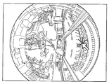
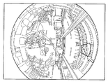
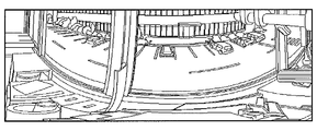
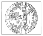
- FIG. 41A shows an example of the omnidirectional image
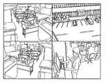
- FIG. 41B shows an example of displaying a panoramic image of the omnidirectional image
- FIG. An example is shown.
- FIGS. 41A to 41C when an omnidirectional image is acquired, a plurality of distortion corrections can be performed on the omnidirectional image.
- the conventional surveillance camera can obtain a cutout distortion corrected image by arbitrarily specifying a cutout range, that is, a cutout view angle and a cutout position in the entire surrounding image.
- a moving image can be taken and the cutout range can be changed in real time. For example, it is possible to generate a cutout distortion-corrected image of the cutout range while detecting the moving body in the image and changing the cutout range so as to track the moving body.
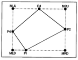
- FIG. 18 is a diagram for explaining processing in Patent Document 1.
- P1 to P4 are vertices of the mask area
- MLU, MRU, MLD, and MRD are vertices of a horizontal ⁇ vertical rectangle circumscribing the figure surrounded by P1 to P4.
- the mask when the mask can be masked only in a horizontal ⁇ vertical rectangle due to the configuration of the signal generator, if the mask area surrounded by P1 to P4 is distorted, it circumscribes the mask area. A region surrounded by MLU, MRU, MLD, and MRD is masked.
- the surveillance camera system of Patent Document 1 only masks the horizontal and vertical rectangles circumscribing the mask areas P1 to P4 at the request of the signal generation unit, and the shape of the mask area is formed from the viewpoint of improving the appearance. It is not deformed. That is, always masking a horizontal ⁇ vertical rectangle circumscribing the mask areas P1 to P4 is not always easy to see.
- a processing range is specified in an image after distortion correction, and the specified processing range is coordinate-projected on a distorted image before distortion correction.
- a range is specified by a method for specifying an arbitrary range for a distorted image as described in Patent Document 2
- the shape of the range varies depending on the presence / absence of distortion correction, the difference in display method, and the image cutout position. Will change. In this state, it is difficult for the user to specify the range, and the position of the specified range is difficult to understand.
- the technique described in Patent Document 2 has a problem that it is necessary to project a large amount of coordinates before and after distortion correction, and the amount of information processing increases.
- An object of the present invention is to provide an image processing apparatus and an image processing method capable of providing a distortion-corrected image including a mask region having a good-looking shape.
- Another object of the present invention is to provide an image processing apparatus and an image processing method that are convenient for designating a mask area on a distorted image while checking the mask area after distortion correction.
- Still another object of the present invention is to provide an image processing apparatus that can specify on a distorted image a processing range that becomes a predetermined type of shape when distortion correction is performed on the distorted image, and check the distorted image. And providing an image processing method.
- Still another object of the present invention is to provide an image processing apparatus and an image processing method capable of improving the ease of user's range specification and reducing the amount of shared information processing before and after distortion correction.
- An image processing apparatus includes: a mask region holding unit that holds a mask region set for a distorted image; a mask processing unit that performs mask processing on the distorted image using the mask region of the mask region holding unit; Using a correction parameter for correcting distortion of the distorted image, a distortion correction unit for correcting the masked distorted image, and a mask region shaping unit for shaping the mask region of the corrected image into a predetermined shape And.
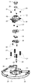
- FIG. 1 is an external view of a camera according to the first embodiment of the present invention.
- FIG. 2 is a partial cutaway perspective view of the camera according to the first embodiment of the present invention.
- FIG. 3 is an exploded perspective view of the optical unit according to the first embodiment of the present invention.
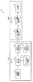
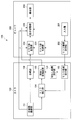
- FIG. 4 is a block diagram showing a configuration of the photographing system according to the first embodiment of the present invention.
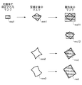
- FIG. 5 is a diagram for explaining the shaping of the mask region in the first embodiment of the present invention.
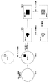
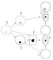
- FIG. 6 is a diagram for explaining the flow of processing in the photographing system according to the first embodiment of the present invention.
- FIG. 7 is a diagram showing processing in the camera and viewer according to the modified example of the first embodiment of the present invention and data exchange between them.
- FIG. 1 is an external view of a camera according to the first embodiment of the present invention.
- FIG. 2 is a partial cutaway perspective view of the camera according to the first embodiment of the present invention.
- FIG. 3 is an exploded perspective view of the
- FIG. 8 is a diagram showing processing in the camera and viewer according to another modified example of the first embodiment of the present invention and data exchange between them.
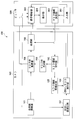
- FIG. 9 is a block diagram showing a configuration of an imaging system according to the second embodiment of the present invention.
- FIG. 10 is a diagram for explaining the flow of processing in the photographing system according to the second embodiment of the present invention.
- FIG. 11 is a block diagram illustrating a configuration of an imaging system according to the third embodiment of the present invention.
- FIG. 12 is a diagram for explaining the flow of processing in the imaging system according to the third embodiment of the present invention.
- FIG. 13A is a diagram illustrating a cutting direction (radial direction) of a first modification of shaping a mask region in the embodiment of the present invention.
- FIG. 13B is a diagram for explaining a cut-out direction (non-radial direction) of a first modification of mask region shaping in the embodiment of the present invention.
- FIG. 14 is a diagram for explaining mask region shaping in a first modification of mask region shaping in the embodiment of the present invention.
- FIG. 15 is a diagram for explaining a second modification of mask area shaping in the embodiment of the present invention.
- FIG. 16 is a diagram for explaining a second modification of mask area shaping in the embodiment of the present invention.
- FIG. 17 is a diagram for explaining a second modification of mask area shaping in the embodiment of the present invention.
- FIG. 18 is a diagram for explaining processing for a conventional mask region.
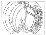
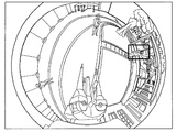
- FIG. 19 is a diagram illustrating an example of a preview image according to the fourth embodiment of the present invention.
- FIG. 19 is a diagram illustrating an example of a preview image according to the fourth embodiment of the present invention.
- FIG. 20 is a block diagram of an imaging system according to the fourth embodiment of this invention.
- FIG. 21 is a diagram illustrating an example of an omnidirectional image according to the fourth embodiment of this invention.
- FIG. 22 is a diagram illustrating an example of mask area designation according to the fourth embodiment of this invention.
- FIG. 23 is a diagram illustrating an example of mask area designation according to the fourth embodiment of this invention.
- FIG. 24 is a diagram illustrating an example of a cutout distortion corrected image according to the fourth embodiment of the present invention.
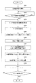
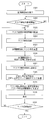
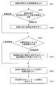
- FIG. 25 is a flowchart for explaining a procedure for generating a preview image in the fourth embodiment of the present invention.
- FIG. 26 is an operation flowchart of the photographing system according to the fourth embodiment of the present invention.
- FIG. 21 is a diagram illustrating an example of an omnidirectional image according to the fourth embodiment of this invention.
- FIG. 22 is a diagram illustrating an example of mask area designation according to the fourth embodiment of this invention.
- FIG. 23 is a diagram
- FIG. 27 is a block diagram of an imaging system according to the fifth embodiment of this invention.
- FIG. 28 is a flowchart for explaining the procedure for generating a preview image in the fifth embodiment of the invention.
- FIG. 29 is an operation flowchart of the imaging system according to the fifth embodiment of the present invention.
- FIG. 30 is a block diagram of an imaging system according to the sixth embodiment of this invention.
- FIG. 31 is a flowchart for explaining a procedure for generating a preview image in the sixth embodiment of the present invention.
- FIG. 32 is an operation flowchart of the imaging system according to the sixth embodiment of the present invention.
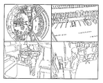
- FIG. 33A is a diagram showing an example in which a mask region is designated on the entire peripheral image in the modification of the present invention.
- FIG. 33A is a diagram showing an example in which a mask region is designated on the entire peripheral image in the modification of the present invention.
- FIG. 33B is a diagram showing an example in which a clipping range is specified on the entire peripheral image in the modification of the present invention.
- FIG. 33C is a diagram showing an example in which display of a preview image is instructed on the entire peripheral image in the modification of the present invention.
- FIG. 33D is a diagram showing a display example of a preview image in a modification of the present invention.
- FIG. 34 is a flowchart showing the operation of the photographing system according to the seventh embodiment of the present invention.
- FIG. 35 is a block diagram showing an imaging system according to the seventh embodiment of the present invention.
- FIG. 36A is a diagram illustrating a processing range (when stored as a set of coordinates) stored in the range storage unit according to the seventh embodiment of the present invention.
- FIG. 36B is a diagram illustrating a processing range (when stored as a set of functions) stored in the range storage unit according to the seventh embodiment of the present invention.
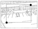
- FIG. 37A is a diagram illustrating designation of the start point of the processing range by the user according to the seventh embodiment of this invention.
- FIG. 37B is a diagram illustrating designation of an end point of a processing range by a user according to the seventh embodiment of this invention.
- FIG. 38A is a diagram illustrating a start point and an end point of the processing range designated on the omnidirectional image according to the seventh embodiment of the present invention.
- FIG. 38B is a diagram illustrating a display range that is determined in accordance with designation of a processing range according to the seventh embodiment of this invention.
- FIG. 39 is a diagram illustrating a processing range superimposed and displayed on a preview image according to the seventh embodiment of the present invention.
- FIG. 40A is a diagram illustrating a display example of the cutout distortion corrected image in the normal mode according to the seventh embodiment of the present invention.
- FIG. 40B is a diagram illustrating a display example of a panoramic image in the normal mode according to the seventh embodiment of the present invention.
- FIG. 41A is a diagram illustrating an example of a conventional omnidirectional image.
- FIG. 41B is a diagram illustrating an example in which cut-out images of a plurality of cut-out ranges are displayed side by side with a conventional omnidirectional image.
- FIG. 41C is a diagram illustrating an example of displaying a panoramic image of a conventional omnidirectional image.
- FIG. 40A is a diagram illustrating a display example of the cutout distortion corrected image in the normal mode according to the seventh embodiment of the present invention.
- FIG. 40B is a diagram illustrating a display
- FIG. 42 is a block diagram illustrating a configuration of an imaging system according to the eighth embodiment of the present invention.
- FIG. 43 is a flowchart showing the processing of the photographing system according to the eighth embodiment of the present invention.
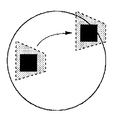
- FIG. 44 is a flow diagram illustrating processing of the range generation unit according to the eighth embodiment of this invention.
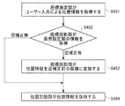
- FIG. 45 is a flowchart showing processing for generating position information in the eighth embodiment of the present invention.
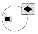
- FIG. 46 is a diagram illustrating an example of image processing according to the eighth embodiment of the present invention.
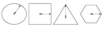
- FIG. 47A is a diagram illustrating an example of range information according to the eighth embodiment of this invention.
- FIG. 47B is a diagram illustrating an example of range information according to the eighth embodiment of this invention.
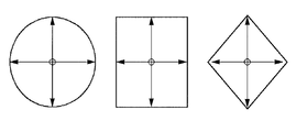
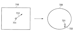
- FIG. 48 is a diagram illustrating an example of designating the shape direction according to the eighth embodiment of the present invention.
- FIG. 49A is a diagram illustrating an example of a conventional omnidirectional image.
- FIG. 49B is a diagram illustrating an example of displaying a panoramic image of a conventional omnidirectional image.
- FIG. 49C is a diagram illustrating an example in which cut-out images of a plurality of cut-out ranges are displayed side by side with a conventional omnidirectional image.
- An image processing apparatus performs mask processing on a distorted image using a mask region holding unit that holds a mask region set for the distorted image, and a mask region of the mask region holding unit.
- a shaping unit performs mask processing on a distorted image using a mask region holding unit that holds a mask region set for the distorted image, and a mask region of the mask region holding unit.
- the image processing apparatus may include a mask region detection unit that detects a mask region of the image corrected by the distortion correction unit.
- the mask region shaping unit converts the mask region detected by the mask region detection unit into a predetermined shape. You may shape it.
- the detected mask area can be shaped.
- the mask area shaping unit may shape the mask area so as to be a rectangle surrounded by lines perpendicular and parallel to the image.
- the mask area can be suitably shaped into a good-looking shape.
- the mask region shaping unit may shape the mask region so that a curved line becomes a straight line by distortion correction by the distortion correction unit.
- the mask area can be shaped into a natural and attractive shape.
- the distorted image may be an image cut out from the omnidirectional image, and the mask area shaping unit shapes the mask area according to the extraction direction of the distorted image from the omnidirectional image. Good.
- the mask area can be shaped so that the erect direction of the subject is aligned with the erect direction of the mask area in the image cut out from the entire surrounding image.
- the distortion correction unit may perform correction by linearly interpolating the coordinates of the conversion source for each square composed of a plurality of pixels and filling in the corresponding coordinate pixels.
- the square including the corrected mask area may be used as the mask area after shaping.
- the mask area can be shaped along the boundary of the square, not the area including the oblique side or the curved side, the appearance of the mask area can be suitably improved.
- the mask area shaping unit may use a plurality of squares including a square including the corrected mask area as a whole as a rectangular area after shaping.
- the mask area can be shaped using the square used for distortion correction, the appearance of the mask area can be suitably improved.
- the image processing apparatus may include an imaging unit that inputs a distorted image.
- the appearance of the mask area in the distortion-corrected image is improved for the distorted image input from the imaging unit.
- the imaging unit may include a fisheye lens.
- the image processing apparatus includes: a designation unit for a user to designate a mask area held by a mask area holding unit on a distorted image; and a mask for correcting the mask area designated by the designation unit using a correction parameter.
- An area correction unit may be provided, and when the user designates the mask area, the corrected mask area may be displayed at the same time.
- the image processing apparatus includes: a designation unit for a user to designate a mask area held by a mask area holding unit on a distorted image; and a mask for correcting the mask area designated by the designation unit using a correction parameter.
- An area correction unit may be provided, and when the user designates the mask area, the corrected mask area may be superimposed and displayed on the distorted image.
- the specified mask area can be confirmed on the distorted image.
- An image processing apparatus uses a mask area holding unit that holds a mask area set for a distorted image, and a correction parameter that corrects distortion of the distorted image.
- a mask area correction unit for correcting the mask area of the holding unit, a mask area shaping unit for shaping the mask area corrected by the mask area correction unit into a predetermined shape, and a correction parameter for the mask area shaped by the mask area shaping unit
- An inverse transformation correction unit that performs inverse transformation using a mask, a mask processing unit that performs mask processing on a distorted image using the mask region inversely transformed by the inverse transformation correction unit, and mask processing using the correction parameter
- a distortion correction unit that corrects a distorted image.
- the mask area to be corrected can be shaped so as to have a shape that is easy to see after the distortion correction on the distorted image subjected to the mask processing in the mask area.
- An image processing apparatus uses a mask area holding unit that holds a mask area set for a distorted image and a correction parameter that corrects distortion of the distorted image.
- a distortion correction unit that corrects a distorted image
- a mask region correction unit that corrects the mask area of the mask area holding unit, using a correction parameter
- a mask that shapes the mask area corrected by the mask area correction unit into a predetermined shape
- the image processing apparatus includes a region shaping unit and a mask processing unit that performs mask processing on the mask region shaped by the mask region shaping unit with respect to the image corrected by the distortion correction unit.
- each of the distorted image and the mask area is corrected, and the mask area is shaped so that it looks better, and then applied to the distortion corrected image.
- An image processing method includes a step of acquiring a distorted image, a step of holding a mask area set for the distorted image, and performing mask processing on the distorted image using the mask area. Performing a step, correcting a masked strained image using a correction parameter for correcting distortion of the strained image, and shaping a mask region of the corrected image into a predetermined shape.
- This configuration also improves the appearance of the masked area in the distortion-corrected image obtained by correcting the distortion of the distorted image.
- FIG. 1 is an external view of a camera in the present embodiment.
- FIG. 2 is a partial cutaway perspective view of the camera according to the present embodiment.
- the camera 100 includes a housing 11, a dome cover 12, and a base 13.
- the camera 100 is used, for example, for facility monitoring and is installed on the wall or ceiling of the facility.
- the outer periphery of the camera 100 is covered with a casing 11 formed in an annular shape with synthetic resin or the like, and a transparent plastic dome cover 12 is disposed at the center.
- the outer surface side of the base 13 is attached to a wall, ceiling, or the like by means of a mounting bracket 18 or the like. In that case, the dome cover 12 faces downward.
- a component housing space is formed around the optical unit 14 of the base 13, and a main board 15 for image processing and power supply is provided.
- a control unit (not shown) including a CPU and a storage unit is mounted.
- the optical unit 14 includes a fisheye lens 16 supported by a lens holder 19 and an opening / closing cover 17.
- FIG. 3 is an exploded perspective view of the optical unit in the present embodiment.
- the fisheye lens 16 is attached to the lens holder 19 via a packing material 20.
- a MOS holder 24 is fixed to the sensor substrate 21 connected to the main substrate 15 by fixing screws 23.
- the sensor substrate 21 to which the MOS holder 24 is fixed is fixed to the lower surface side of the lens holder 19 by a MOS blanket 25 and a fixing screw 26.
- the base 13 is provided with four fitting bosses 29 for fixing the support pillars 28 respectively.
- Each support column 28 passes through the through hole 22 of the lens holder 19 and is fixed by a fixing screw 21.
- a coil spring 27 is extrapolated between the base 13 and the through hole 22 of the lens holder 19, and the coil spring 27 biases the lens holder 19 in a direction to float from the base 13.
- FIG. 4 is a block diagram showing the configuration of the photographing system of the present embodiment.
- the imaging system 101 includes a camera 110 and a viewer 210.
- the camera 110 is a surveillance camera installed at a location to be monitored.
- the viewer 210 is connected to the camera 110 so as to be able to communicate with each other by wire or wirelessly.
- the viewer 210 is, for example, a computer and a monitor provided in a monitoring room, or a portable terminal carried by a monitoring person.
- the camera 110 includes an omnidirectional imaging unit 111, a mask data holding unit 112, a mask execution unit 113, an extraction parameter setting unit 114, and an extraction distortion correction unit 115.
- the omnidirectional imaging unit 111 processes the image data obtained by the fisheye lens, the imaging element on which light from the subject (monitoring target) incident through the fisheye lens is formed, and the image signal obtained by the imaging element, and outputs the image data. This is a known all-around camera including a processing unit to be generated.
- the omnidirectional imaging unit 111 outputs the omnidirectional image generated by shooting to the mask execution unit 113.
- the all-around image is an image taken with a fisheye lens at a horizontal angle of view of about 360 degrees, and is a circular or donut-shaped image.
- the omnidirectional image is distorted, and the degree of the distortion increases as the outer periphery of the image is closer.
- the viewer 210 can also display an image from which distortion has been removed, as will be described later.
- the mask data holding unit 112 holds data representing a mask area on the entire surrounding image (hereinafter also referred to as “mask data” or “mask area”). That is, the mask data held in the mask data holding unit 112 is data indicating the shape of the mask area, its direction, and its position on the entire peripheral image.
- the user can set an arbitrary area in the entire surrounding image as a mask area. That is, the user can set a mask area of an arbitrary shape (for example, a rectangle, an ellipse, a circle, etc.) at an arbitrary position in the entire surrounding image, and can store it in the mask data holding unit 12. Note that mask regions may be set at a plurality of locations in the entire peripheral image.
- the mask execution unit 113 performs a mask process on the mask area set in the mask data holding unit 112 in the all-around image acquired from the all-around imaging unit 111.
- the masking process is a process for reducing the amount of information obtained from an image.
- the resolution of the area is low. This includes processing to convert to (mosaic processing), processing to convert to an image as seen through a rasp glass, and the like.
- a process of painting in one color is adopted.
- the extraction parameter setting unit 114 sets an extraction parameter indicating the extraction range in the entire surrounding image.
- the extraction parameters include, for example, center coordinates of the extraction range, zoom rate (size of the extraction range on the entire surrounding image), and parameters of the extraction direction.
- the cutout distortion correction unit 115 cuts out the cutout range specified by the cutout parameter set by the cutout parameter setting unit 114 from the entire surrounding image in which the mask processing is performed on the mask area by the mask execution unit 113, and distortion is determined. A distortion corrected image is generated by correcting so that it disappears.
- the cutting parameters set in the cutting parameter setting unit 114 are: This is a correction parameter used in the processing of the cutout distortion correction unit 115.
- the clipping parameters set in the clipping parameter setting unit 114 may be set by the user, or a predetermined subject is recognized when the camera 110 itself performs image recognition processing on the entire surrounding image. It may be set so as to include a region.
- the cutout distortion correction unit 115 generates a distortion correction image by cutting out the cutout range of the all-around image subjected to the mask process and performing distortion correction.
- the cutout distortion correcting unit 115 corrects the mask area applied to the all-around image by performing distortion correction on the cutout range of the all-around image.
- the distortion correction image is transmitted to the viewer 210 via a communication interface (not shown). The viewer 210 receives this distortion corrected image.
- the viewer 210 includes a mask area detection unit 211, a mask area shaping unit 212, and an output unit 213.
- the mask area detection unit 211 acquires a distortion correction image transmitted from the camera 110 and detects a mask area from the distortion correction image. In this embodiment, since the mask area is filled with one color, the color area is detected as a mask area. The detected mask area is output to the mask area shaping unit 212 together with the distortion corrected image.
- the mask region shaping unit 212 shapes the shape of the mask region detected by the mask region detection unit 211 into a shape that is easy to see by a method described later, and performs mask processing again on the distortion-corrected image with the shaped shape.
- the output unit 213 is a display device that displays a distortion-corrected image that has been subjected to mask processing again by the mask region shaping unit 212.
- FIG. 5 is a diagram for explaining mask region shaping in the mask region shaping unit 212.
- a rectangular mask area mo ⁇ b> 1 composed of horizontal and vertical sides is set in the mask data holding unit 112 on the entire surrounding image that is the original image.
- the original mask area mo1 is, for example, FIG.
- the mask area mm1 is corrected.
- the mask area applied to the omnidirectional image before distortion correction has a rectangular shape composed of horizontal and vertical sides, and has a well-defined shape. It has become.
- the mask area after distortion correction shown in this figure is an example, and is actually a shape determined by a distortion correction parameter determined from lens distortion or the like, and is not limited to a quadrangle but a shape including a curve There is also.
- the mask area shaping unit 212 shapes such a distorted rectangular mask area into a rectangle composed of horizontal and vertical sides including all or part of the mask area.
- the mask area ms11 after shaping is a rectangle including horizontal and vertical sides that completely include a square distorted by distortion correction
- the mask area ms12 after shaping is obtained by distortion correction.
- the mask area shaping unit 22 performs the mask process again on these rectangular ms11 or ms12 areas.
- the mask region mm2 after distortion correction has a shape that is a curved line with four sides recessed by distortion correction.
- the mask region shaping unit 22 shapes the concave curved portion in the mask region mm2 having such a shape so as to be a straight line.
- the mask region mm3 after distortion correction has a shape in which two opposing sides are concave curves, and the other two opposing sides are convex curves. Yes.
- the mask region shaping unit 212 shapes the concave curved portion in the mask region mm3 having such a shape into a straight line and also forms the convex curved portion into a straight line.
- FIG. 6 is a diagram for explaining the flow of processing in the photographing system 101.
- the omnidirectional imaging unit 111 captures the omnidirectional image IM11 by photographing the monitoring target part (step S61).
- the all-around image IM11 is a circular image as shown in FIG. 6 and is distorted with increasing degree toward the outer periphery.
- the mask execution unit 13 performs mask processing on the mask area MA11 read from the mask data holding unit 12 with respect to the all-around image IM11 (step S62). Thereby, the all-around image IM11 becomes an image IM12 in which the mask process is performed on the mask area MA11.
- the cutout range (ie, correction parameter) set by the cutout parameter setting unit 112 is used to cut out the cutout range and perform distortion correction.
- Step S63 the image is extracted from the omnidirectional image IM12 that has been subjected to the mask processing in a state in which the extraction range is corrected for distortion, and a distortion corrected image IM13 is obtained.
- This distortion correction image IM13 includes a mask area MA12, but the mask area MA12 is corrected by the cutting and distortion correction by the cutting distortion correction unit 15 so that the original mask area MA11 is corrected to have a distorted shape. Yes.
- the distortion-corrected image IM13 generated in this way is transmitted from the camera 110 to the viewer 210 and given to the mask area detection unit 211 of the viewer 210.
- the mask area detection unit 211 detects a mask area from the distortion corrected image IM13 (step S64).
- the mask area shaping unit 212 shapes the mask area to obtain a shaped mask area MA13 (step S65).
- the mask area MA13 after shaping is a rectangle composed of horizontal and vertical sides surrounding the original distorted mask area MA12.
- the mask area shaping unit 212 performs mask processing on the distortion-corrected image IM13 for the mask area MA13 after shaping (step S66). In this way, the mask area shaping unit 212 obtains a distortion-corrected image IM14 in which a mask process is performed on a rectangular mask area MA13 having horizontal and vertical sides.
- a masking process is performed on a distorted omnidirectional image using a desired region as a mask region, and then such an image is processed.
- Perform distortion correction This distortion correction eliminates the distortion of the image other than the mask area, but the mask area has a distorted shape. Therefore, the mask area detection unit 211 detects a mask area from the distortion-corrected image, the mask area shaping unit 212 shapes the mask area into a good-looking shape, and performs mask processing again. Therefore, in the finally obtained distortion-corrected image, the masked region has a good-looking shape.
- the mask data holding unit 112, the mask execution unit 113, the extraction parameter setting unit 114, and the extraction distortion correction unit 115 are provided in the camera 110, and the mask region detection unit 211 and the mask region shaping unit are provided.
- the unit 212 is provided in the viewer 210, but these components may be provided in either the camera 110 or the viewer 210.
- the camera 110 may be provided with only the omnidirectional imaging unit 111, and all other components may be provided in the viewer 210.
- FIG. 7 is a diagram showing processing in the camera 110 and the viewer 210 and data exchange between them in this case.
- the cutout correction unit 115 cuts out the entire peripheral image cutout region to perform cutout correction (step S73), and the output unit 213 displays the distortion correction image (step S74).
- description regarding the mask processing is omitted.
- FIG. 8 shows processing in the camera 110 and the viewer 210 and exchange of data between them when the clipping parameter setting unit 114 is modified to be included in the viewer 210 with respect to the imaging system 101 having the configuration shown in FIG. FIG.
- imaging is performed by the omnidirectional imaging unit 111 of the camera 110 (step S81), and when the extraction range is specified by the extraction parameter setting unit 114 of the viewer 210 (step S82), the extraction range is changed.
- the specified clipping parameter is transmitted from the viewer 210 to the camera 110 (step S83).
- the cutout distortion correction unit 115 of the camera 110 performs distortion correction on the entire surrounding image using the cutout parameter as a correction parameter (step S84) to obtain a distortion correction image.
- the distortion corrected image is transmitted from the camera 110 to the viewer 210 (step S85) and displayed on the output unit 213 (step S86).
- FIG. 9 is a block diagram illustrating a configuration of an imaging system according to the second embodiment.
- the imaging system 102 according to the second embodiment includes a camera 120 and a viewer 220.
- the same components as those in the first embodiment are denoted by the same reference numerals, and detailed description thereof is omitted.
- the camera 120 includes an omnidirectional imaging unit 111, a mask data holding unit 112, a mask execution unit 113, an extraction distortion correction unit 115, and a mask area shaping unit 126.
- the mask region shaping unit 126 shapes the mask region read from the mask data holding unit 112 so that the mask region shaping unit 126 has a good-looking shape by receiving distortion correction in the cutout distortion correction unit 115.
- the mask execution unit 113 performs mask processing on the entire peripheral image for the mask region having such a pre-shaped shape, and the cutout distortion correction unit 115 performs mask processing on the mask region. Cutout distortion correction is performed on the applied all-around image.
- the camera 120 has a mask area shaping unit 126 between the mask holding unit 112 and the mask execution unit 113.
- the mask area shaping unit 126 includes a corrected mask area generation unit 1261, a corrected mask area shaping unit 1262, and an inverse transformation correction unit 1263.
- the clipping parameters set by the clipping parameter setting unit 114 of the viewer 220 are transmitted from the viewer 220 to the camera 120 and given to the post-correction mask area generation unit 161, the inverse transformation correction unit 163, and the clipping distortion correction unit 115 of the camera 120. It is done.
- the post-correction mask region generation unit 1261 reads out the mask region from the mask data holding unit 112, corrects the mask region using the extraction parameter as a correction parameter, and generates a post-correction mask region.
- This mask area correction is performed by the same method as the distortion correction performed by the cutout distortion correction unit 115 using the same cutout parameter.
- the mask data correction unit 112 holds a rectangular mask region composed of horizontal and vertical sides, but the corrected mask region generation unit 1261 performs the above-described correction using the extraction parameter.
- the corrected mask region has a distorted shape. This corrected mask area is given to the corrected mask area shaping unit 1262.
- the post-correction mask area shaping unit 1262 shapes the post-correction mask area so that it looks good.
- the specific method of shaping is as described above.
- the shaped mask area is given to the inverse transformation correction unit 1263.
- the inverse conversion correction unit 1263 performs correction opposite to the correction performed by the post-correction mask region generation unit 1261 and the extraction distortion correction unit 115 using the extraction parameter.
- the mask region having a good appearance shaped by the corrected mask region shaping unit 1262 becomes a distorted shape again.
- This distorted shape is a shape that returns to a good-looking shape obtained by shaping in the corrected mask area shaping unit 1262 by performing distortion correction using the cut-out parameter.
- the mask area subjected to the inverse transformation by the inverse transformation correction unit 1263 is given to the mask execution unit 113, and the mask execution unit 113 performs a mask process on the entire surrounding image in this mask region.
- the cutout distortion correction unit 115 performs cutout and distortion correction using cutout parameters for the entire surrounding image obtained by masking the mask region thus obtained.
- the cut-out parameters used as correction parameters in the cut-out distortion correction unit 115 are the cut-out parameters used for correcting the mask region in the post-correction mask region generation unit 1261 and the inverse transformation correction unit 1263. This is the same parameter as the cut-out parameter used for the inverse transformation in.
- the mask area has a good shape and the distortion other than the mask area is also eliminated.
- the distortion-corrected image after mask processing obtained in this way is transmitted from the camera 120 to the viewer 220, the viewer 220 displays the distortion-corrected image on the output unit 213.
- FIG. 10 is a diagram for explaining the flow of processing in the imaging system 102.
- the corrected mask area generation unit 1261 acquires the mask area MA21 from the mask data holding unit 112, acquires the extraction parameter from the extraction parameter setting unit 14, and uses the extraction parameter as a correction parameter in the mask area MA21. Then, distortion correction is performed, and a corrected mask area MA22 is generated (step S101).
- the post-correction mask area shaping unit 1262 shapes the post-correction mask area MA22 into the post-correction mask area MA23 (step S102).
- the inverse transformation correction unit 1263 obtains a cut-out parameter from the cut-out parameter setting unit 14, and uses the reciprocal number of the cut-out parameter as a correction parameter for the corrected mask area MA23 in the direction opposite to the correction in step S102. Are converted (step S103), and an inverse conversion correction mask area MA24 is obtained.
- the omnidirectional imaging unit 111 acquires the omnidirectional image IM21 by photographing the monitoring target portion (step S104)
- the mask execution unit 113 uses the inverse transformation correction mask area NA obtained by the correction inverse change unit 1263.
- the mask process is performed on the all-around image IM21 (step S105), and the image IM22 subjected to the mask process is obtained.
- the cutout distortion correction unit 115 performs cutout of the cutout range and distortion correction using the cutout parameters set by the cutout parameter setting unit 114 for the image IM22 subjected to this masking process (step S106).
- a distortion corrected image IM23 is obtained.
- mask processing is performed in the mask area having a good appearance shaped by the post-correction mask area shaping unit 1262.
- the mask region is corrected using the same correction parameter as that used in the clipping distortion correction for the entire surrounding image. Is a distorted shape. Then, the mask area having the distorted shape is formed into a mask area having a good appearance, and such a mask area is once inversely transformed by the above correction parameter, and the distortion is obtained using such an area as a mask area. Mask processing is performed on the entire surrounding image. Then, the cutout distortion correction unit 115 performs distortion correction again using the same correction parameters as described above. Thereby, in the distortion correction image obtained in this way, the mask area has a good-looking shape shaped by the post-correction mask area shaping unit 1262.
- the viewer 220 only needs to include the extraction parameter setting unit 114 and the output unit 213 as a configuration related to the present invention. Since the load is not large, the viewer 220 can be realized even in an apparatus with limited processing capability. For example, this embodiment is effective when the viewer 220 is a portable terminal.
- FIG. 11 is a block diagram illustrating a configuration of an imaging system according to the third embodiment.
- the imaging system 103 according to the third embodiment includes a camera 130 and a viewer 230.
- the same components as those in the first embodiment are denoted by the same reference numerals, and detailed description thereof is omitted.
- the camera 130 includes an omnidirectional imaging unit 111, a mask data holding unit 112, a mask execution unit 113, an extraction parameter setting unit 114, an extraction distortion correction unit 115, a mask region distortion correction unit 137, and a mask region shaping unit 138. .
- the mask region distortion correction unit 137 performs extraction of the extraction range and distortion correction on the mask region held in the mask data holding unit 112, using the extraction parameter acquired from the extraction parameter setting unit 114 as a correction parameter, A distortion correction mask area on the entire surrounding image is generated. This distortion correction mask area is a mask area on the cutout range and has a distorted shape.
- the distortion correction mask region is output to the mask region shaping unit 138.
- the mask area shaping unit 138 shapes the distortion correction mask area on the cut-out range generated by the mask area distortion correction unit 137 into a shape having a good appearance.
- a specific shaping method is as described above.
- the cutout distortion correction unit 115 performs cutout of the cutout region and distortion correction using the cutout parameters read out from the cutout parameter setting unit 114 as correction parameters for the entire surrounding image acquired by the all-around imaging unit 111.
- a distortion corrected image is generated.
- the mask execution unit 113 receives the distortion corrected image generated by the cutout distortion correcting unit 115 and the mask area shaped by the mask area shaping unit 138, and the mask area shaped with respect to the distortion corrected image. The mask process is performed.
- the distortion correction image masked by the mask execution unit 113 is transmitted from the camera 130 to the viewer 230.
- the output unit 213 of the viewer 230 displays the distortion corrected image transmitted from the camera 130.
- FIG. 12 is a diagram for explaining the flow of processing in the photographing system 103.
- the mask area distortion correction unit 137 reads out the extraction parameter from the extraction parameter setting unit 114, and uses the correction parameter as a correction parameter to correct the mask area MA31 read out from the mask data holding unit 112 (step S121).
- a region MA32 is generated.
- the mask area distortion correction unit 137 performs distortion correction on the mask area MA31 on the entire peripheral image after cutting out the extraction range using the extraction parameter.
- the mask region shaping unit 138 shapes the mask region corrected by the mask region distortion correction unit 137 into a shape that looks good (step S122), and generates a shaped mask region MA33.
- the clipping distortion correction unit 115 uses the clipping parameter set by the clipping parameter setting unit 114 to use this omnidirectional image.
- a cutout range is cut out from IM31, distortion correction is performed (step S124), and a distortion correction image IM32 is generated.
- the mask execution unit 113 receives the distortion-corrected image IM32 and the mask region MA33 after shaping generated by the mask region shaping unit 138.
- the mask execution unit 113 performs mask processing on the mask area MA33 after shaping with respect to the distortion correction image IM32 (step S125), and generates a distortion correction image IM33 in which the mask area MA33 is masked.
- cutout distortion correction is performed on the mask area and the entire surrounding image using the same cutout parameter.
- the mask region corrected in this way is shaped and applied to the all-around image (distortion corrected image) subjected to cutout distortion correction.
- the viewer 230 only includes the output unit 213 as a configuration related to the present invention, and thus the viewer 230 can be realized even in an apparatus having a small processing capacity.
- the other components are as follows.
- the camera 120 or 130 may be provided, or the viewer 220 or 230 may be provided.
- the extraction parameter setting unit 114 is provided in the viewer 230, and the extraction range can be specified on the viewer 230 side. You may do it.
- a part or all of the components other than the omnidirectional imaging unit 111 and the output unit are separate from the camera and the viewer, and between the camera and the viewer. It may be provided in the apparatus provided in the.
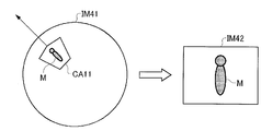
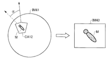
- FIG. 13 is a diagram for explaining a cutting direction by the cutting distortion correction unit 115 described in the first to third embodiments.
- FIG. 13A shows a case of cutting out in a radial direction of a circular omnidirectional image
- FIG. 13B shows cutting out in a direction different from the radial direction of the omnidirectional image (a direction that forms an angle ⁇ with the cutting direction in FIG. 13A). Shows the case.
- cutting out in a certain direction means cutting out a rectangular image after cutting out the cutout range and correcting the distortion so that the certain direction is on the top.
- the erecting direction of the subject including the person M shown in the extraction range CA11 coincides with the vertical direction in the distortion correction image IM42.
- the distortion correction image is generated by cutting out in the direction that forms the angle ⁇ with the radial direction.
- the upright direction of the subject including the person M shown in the cutout range CA12 is the distortion correction image IM43. Is inclined by an angle ⁇ from the vertical direction at.
- FIG. 14 is a diagram for explaining mask area shaping in the case of FIGS. 13A and 13B.
- the cutout area CA11 is cut out in the radial direction and the erecting direction of the subject in the distortion correction image IM42 coincides with the vertical direction of the distortion correction image IM42, the mask area MA41 having a distorted shape by distortion correction is displayed.
- the mask area MA42 By shaping the mask area MA42 so as to be surrounded by an upright rectangle, the mask shape can be easily seen by the user.
- the distortion correction results in a distorted shape. If the mask area MA44 is such that the mask area MA43 is surrounded by an upright rectangle, the subject is tilted, but the mask area MA44 is upright, which causes a sense of incongruity.
- the distortion is corrected by distortion correction in consideration of the inclination.
- the mask area MA43 having the shape is shaped. Specifically, the mask area MA43 is shaped into a mask area MA45 having a direction inclined by the same angle as the inclination angle of the cutout direction with respect to the radial direction.
- the erect direction of the subject matches the formation direction of the mask area after shaping, so that natural mask process without a sense of incongruity is performed.
- a corrected distortion image is obtained.
- FIGS. 15 to 17 are diagrams for explaining a second modified example of shaping a mask region.
- processing for generating a distortion corrected image by cutting out a cutout range from the entire surrounding image and performing distortion correction will be described.
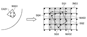
- the pixels in the cutout area CA21 in the all-around image IM51 are each coordinate-converted and projected onto the distortion corrected image.
- the pixels P11, P12, and P13 in the omnidirectional image IM51 are P21, P22, and P23 on the distortion corrected image, respectively.
- Pixels that are deficient in the distortion-corrected image are filled, for example, by linearly interpolating the coordinates of the conversion source for each square of 16 pixels, and finally a distortion-corrected image IM52 is generated.
- FIG. 16 is a diagram illustrating a first method of the present modification.
- the mask area MA51 set there is a distorted mask area.
- MA52 a plurality of squares that surround the mask area MA52 and are entirely rectangular are defined as a mask area MA53 after shaping.
- the square of the line including the square SQ1 including the uppermost point of the mask area MA52 that has been distorted by distortion correction is set as the uppermost square of the mask area after shaping
- the rightmost point of the mask area MA52 is
- the square of the column including the square SQ2 is the square of the rightmost column of the mask area after shaping
- the square of the row including the square SQ3 including the lowest point of the mask area MA52 is the square of the bottom line of the mask area after shaping.
- the square of the column including the square SQ4 including the leftmost point of the mask area MA52 is surrounded by the uppermost row, the rightmost column, the lowermost row, and the leftmost column as the leftmost column square of the mask region after shaping.
- a rectangular area is defined as a mask area MA53 after shaping.
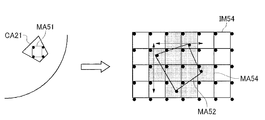
- FIG. 17 is a diagram showing a second method of this modification.
- the square (only) including the mask area MA52 that has been distorted by distortion correction is used as the mask area MA54 after shaping.
- the mask area MA54 after shaping is an area consisting of only horizontal and vertical line segments, and since there is no oblique line segment like the mask area MA52 before shaping, the appearance is improved.
- the first to third embodiments of the present invention have been described by taking as an example the case where the cutout range on the omnidirectional image is cut out and distortion correction is performed.
- the present invention can also be applied to a case where a panoramic image is generated by performing distortion correction and mask processing is performed on a partial region of the panoramic image at that time.
- an omnidirectional image is captured as an image having distortion
- an image having distortion is not limited to an omnidirectional image (horizontal angle of view of approximately 360 degrees).
- the present invention is effectively applied to any imaging system that sets a mask region and corrects distortion for an image having distortion.
- each of the fourth to sixth embodiments will be described by taking as an example an imaging system in which the camera uses a fish-eye lens to capture an all-around image as a distorted image.
- the distorted image of the present invention is not limited to the omnidirectional image, but may be any image that is distorted by imaging using a wide-angle lens.
- FIG. 20 is a block diagram showing an image display system according to an embodiment of the present invention.
- the photographing system 104 is configured by connecting a camera 140 and a viewer 240.
- the camera 140 is a surveillance camera
- the camera 140 is installed so as to be able to capture a portion to be monitored
- the viewer 240 is a device for a user to view an image captured by the camera 140 and subjected to image processing.
- the viewer 240 may be, for example, a personal computer or a mobile terminal.
- the camera 140 is a so-called network camera, and may be connected to the viewer 240 by wire or wirelessly.
- the viewer 240 may include a part or all of the configuration of the camera 140 other than the all-around imaging unit 141.
- the camera 140 includes an all-around imaging unit 141, a mask region receiving unit 142, a mask frame generating unit 143, a mask frame superimposing unit 144, a mask executing unit 145, a clipping distortion correcting unit 146, and a combining unit 147.
- the viewer 240 includes an input unit 241, a mask area determination unit 242, a display switching unit 243, and a display unit 244.
- the all-around imaging unit 141 of the camera 140 is an imaging system having a fish-eye lens that is a kind of wide-angle lens.
- the omnidirectional image capturing unit 141 captures a circular omnidirectional image. This all-around image is a distorted image in which the distortion becomes stronger toward the outer periphery.
- the omnidirectional imaging unit 141 outputs the omnidirectional image acquired by imaging to the mask frame superimposing unit 144 and the mask execution unit 145, and transmits it to the viewer 240.
- the image captured and output by the omnidirectional imaging unit 141 may be a still image or a moving image. In the case of a moving image, processing described below is performed for each frame.
- the input unit 241 of the viewer 240 inputs various instructions by the user. These instructions include a display switching instruction, a mask area designation, a mask area cancellation / determination instruction, and the like. Among these, a display switching instruction is input to the display switching section 243, and a mask area designation and mask area cancellation / determination instruction is input to the mask area determination section 242.
- the input unit 241 is, for example, a touch sensor integrated with a mouse and a keyboard or a display unit 244.
- the mask area determination unit 242 obtains a mask area from the input content input by the input unit 241. Specifically, a rectangle (vertical and horizontal sides) with a point on the entire image clicked with the mouse as one vertex and the current pointer position at the opposite corner of that vertex ( (Rectangle). Information on the position and shape of the rectangle on the omnidirectional image (the height in the vertical direction and the width in the horizontal direction) is transmitted to the camera 140 as instruction information for the mask area.
- the mask area receiving unit 142 receives the instruction information of the mask area determined by the mask area determining unit 242 and outputs it to the mask frame generating unit 143 and the mask executing unit 145.
- the mask frame generation unit 143 generates a mask frame indicating the extension of the mask region based on the mask region instruction information obtained from the mask region reception unit 142. This mask frame also includes information indicating the position of the mask frame in the entire surrounding image.
- the mask frame superimposing unit 144 acquires the all-around image from the all-around imaging unit 141, acquires the mask frame from the mask frame generating unit 143, and superimposes the shape of the mask frame on the all-around image.
- the mask frame superimposing unit 144 outputs the all-around image on which the mask frame is superimposed to the synthesizing unit 147 and the display switching unit 243.
- the mask execution unit 145 acquires an all-around image from the all-around imaging unit 141, acquires mask area designation information from the mask area reception unit 142, and applies the mask area corresponding to the designation information in the all-around image to the mask area. Then, mask processing is performed.
- the mask process performed by the mask execution unit 145 according to the present embodiment is a process of painting the mask area black. However, the mask process is not limited to this, and other mask processes may be used as long as the process reduces the information amount of the image in the mask area, such as a mosaic process.
- the mask execution unit 145 outputs the all-around image that has been subjected to the mask process in the mask area, and outputs the image to the distortion correction unit 146.
- the cutout distortion correction unit 146 cuts out a cutout range of the entire surrounding image that has been subjected to mask processing in the mask area, performs distortion correction, and generates a cutout distortion corrected image.
- the cutout range is determined in advance. Note that a frame indicating the cutout range may be displayed so as to be superimposed on the entire surrounding image.
- the cutout distortion correction unit 146 outputs the cutout distortion correction image to the synthesis unit 147 and transmits the image to the viewer 240.
- the synthesizing unit 147 obtains the entire image obtained by superimposing the mask frame obtained from the mask region frame superimposing unit 144 and the cutout distortion corrected image obtained from the cutout distortion correcting unit 146 and already subjected to mask processing in the mask region. A composite image is generated to generate a preview image that displays both images simultaneously. The composition unit 147 transmits the generated preview image to the viewer 240.
- the display switching unit 243 receives the omnidirectional image from the omnidirectional imaging unit 141, receives the omnidirectional image on which the mask frame is superimposed from the mask frame superimposing unit 144, and performs mask processing on the mask area from the clipping correction unit 146.
- the clipped distortion corrected image thus received is received, and a preview image is received from the synthesizing unit 147.
- the imaging system 104 is provided with a mask area designation mode for determining a mask area and a normal mode for displaying a cutout distortion corrected image obtained by performing mask processing on the mask area. These display modes are switched based on an input from the input unit 241.
- the display switching unit 243 acquires mode switching information from the input unit 241 and switches the display mode.
- the display switching unit 243 In the mask area designation mode, the display switching unit 243 first outputs the all-around image obtained from the all-around imaging unit 141 to the display unit 244. When the omnidirectional image with the mask frame superimposed is obtained from the mask frame superimposing unit 144 in the mask area designation mode, the display switching unit 243 outputs the omnidirectional image with the mask frame superimposed to the display unit 244. When the preview image is obtained from the synthesis unit 147, the preview image is output to the display unit 244. Further, in the normal mode, the display switching unit 243 displays either the omnidirectional image obtained from the omnidirectional imaging unit 141 or the cutout distortion corrected image obtained by performing mask processing on the mask area obtained from the cutout distortion correcting unit 146. Output to the unit 244. It is instructed from the input unit 241 to output either the omnidirectional image or the cut-out distortion corrected image subjected to mask processing.
- the display unit 244 displays the image obtained from the display switching unit 243.
- the display unit 244 is, for example, a liquid crystal display device including a liquid crystal display panel.
- the display unit 244 is an input unit 241 touch sensor, the display unit 244 is a touch panel integrated therewith.
- FIG. 21 is a diagram illustrating an example of the omnidirectional image according to the present embodiment.
- the horizontal viewing angle of the omnidirectional imaging unit 141 is 360 degrees, and the omnidirectional image is circular as shown in FIG.
- This circular all-around image has a distorted image, the degree of which is not uniform over the entire image area, and the distortion increases as it approaches the circular edge.
- the omnidirectional image shown in FIG. 21 is displayed when display of the omnidirectional image is selected in the normal mode and when the mask area is designated in the mask area designation mode.
- FIG. 22 is a diagram showing an example of mask area designation according to the embodiment of the present invention.
- a mask area is designated on the entire peripheral image.
- a pointer that moves in accordance with the operation of the mouse as the input unit 241 is displayed on the entire peripheral image, and the start point of the mask area is designated by clicking the mouse.
- the mask area determination unit 242 makes a rectangle composed of a side parallel to the vertical direction of the screen and a side parallel to the horizontal direction of the screen, with the start point and the position of the pointer as diagonal vertices. Is required.
- an all-around image in which the mask frame is superimposed by the mask frame superimposing unit 144 is generated using the rectangular information (mask area designation information), it is displayed on the display unit 244.
- FIG. 23 is a diagram showing an example of mask area designation according to the embodiment of the present invention.
- a frame indicating the obtained rectangle is superimposed on the all-around image.
- the pointer is moved to create a frame indicating the desired mask area, when the mouse is clicked again at that position, a preview image is generated using the mask area designation information at that time and displayed on the display unit 244.
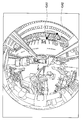
- FIG. 19 is a diagram showing an example of a preview image according to the embodiment of the present invention.
- the cutout distortion corrected image in which the mask process is performed on the mask area is superimposed and displayed on the entire peripheral image on which the mask frame is superimposed.
- the cutout distortion corrected image is arranged in a balloon blown out from the mask frame superimposed on the entire surrounding image.
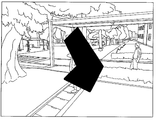
- FIG. 24 is a diagram showing an example of a cutout distortion corrected image according to the embodiment of the present invention.
- This cutout distortion corrected image is displayed when display of the cutout distortion corrected image is selected in the normal mode.
- the mask processing is performed on the determined mask region.
- this mask area is specified and fixed as a rectangular area on the entire peripheral image, the cutout distortion corrected image is rectangular by the distortion correction when generating it from the entire peripheral image.
- the designated mask area has a distorted shape.
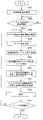
- FIG. 25 is a flowchart for explaining a procedure for generating a preview image in the fourth embodiment of the present invention.
- a procedure for generating a preview image in the present embodiment will be described with reference to FIG.
- the omnidirectional imaging unit 141 captures the omnidirectional image D71.
- a mask area D72 is designated on the entire peripheral image.
- the mask frame superimposing unit 144 uses the mask region D72 to generate the omnidirectional image D73 in which the generated mask frame is superimposed on the omnidirectional image D71.
- the mask execution unit 145 performs a mask process in the mask area D72 on the all-around image D71, and generates an all-around image D74 in which the mask process is performed on the mask area.
- the cutout distortion correction unit 146 performs cutout and distortion correction of the cutout range on the entire peripheral image D74 in which the mask process is performed on the mask area, and the cutout distortion correction image D75 in which the mask process is performed on the mask area. Is generated.
- the compositing unit 147 superimposes a balloon including the cutout distortion corrected image D75 masked in the mask area on the entire surrounding image D73 in which the mask frame is superimposed on the mask area, and previews it. An image D76 is generated.
- FIG. 26 is an operation flowchart of the photographing system according to the fourth embodiment of the present invention.
- the flow in FIG. 26 shows the operation of the imaging system 104 in the mask area designation mode.
- the operation of the imaging system 104 of the fourth embodiment will be described.
- the omnidirectional imaging unit 141 captures an omnidirectional image, and the display unit 244 displays it (step S261).
- it is determined by the input unit 241 whether or not the mask area has been designated step S262. Specifically, when the start point of the mask area is clicked by the operation of the input unit 241, it is determined that the designation of the mask area has started. If the designation of the mask area has not started (NO in step S262), the entire surrounding image is displayed and waits until the designation of the mask area is started.
- the mask area is determined according to the movement of the pointer by the mouse operation.
- the determination unit 242 obtains the mask area and transmits the designation information to the camera 140, and the mask area reception unit 142 acquires the designation information of the mask area (step S263).
- the mask frame generation unit 143 generates a mask frame based on the mask area designation information (step S264), and the mask frame superimposition unit 144 superimposes the mask frame on the entire surrounding image (step S265).
- the generation of the mask frame and the superimposition on the entire surrounding image are performed according to the position of the pointer while the pointer moves after the start point is clicked.
- the mask execution unit 145 determines the provisionally confirmed mask area (hereinafter simply referred to as “mask area”) for the entire surrounding image.
- mask processing for masking is performed (step S266).
- the cut-out distortion correction unit 146 performs cut-out and distortion correction of the cut-out range from the all-around image on which the mask processing has been performed on the mask area, and generates a cut-out distortion correction image (step S267). In this cutout distortion corrected image, mask processing is performed on the mask area.
- the synthesizing unit 147 combines the omnidirectional image on which the mask frame is superimposed and the cutout distortion corrected image in which the mask process is performed on the mask region, generates a preview image (step S268), and transmits the preview image to the viewer 240.
- the display switching unit 243 of the viewer 240 Upon receiving the preview image, the display switching unit 243 of the viewer 240 outputs the preview image to the display unit 244, and the display unit 244 displays the preview image (step S269).
- the user determines whether or not the mask area indicated by the preview image has been confirmed with respect to the input unit 241 (step S270). When the mask area indicated by the preview image is confirmed (YES in step S270), The process ends.
- display switching unit 243 switches the image output to display unit 244 to the all-around image, The process returns to step S263 where the mask area designation information is acquired again.
- the mask area is specified on the entire surrounding image, and the specified mask area is displayed on the preview image. It is shown to be recognizable on the omnidirectional image, and the distortion is corrected including this mask area, and the cut out distortion corrected image capable of recognizing the mask area is also displayed at the same time. It is possible to confirm the position and shape of the region in the cutout distortion corrected image. If the mask area is acceptable as a result of the confirmation, the mask area can be determined by instructing “decision” to the preview image.
- FIG. 27 is a block diagram of an imaging system according to the fifth embodiment of this invention.
- the photographing system 105 is configured by connecting a camera 150 and a viewer 250.
- the camera 150 is a surveillance camera
- the camera 150 is installed so as to be able to capture a portion to be monitored
- the viewer 250 is a device for a user to view an image captured by the camera 150 and subjected to image processing.
- the viewer 250 may be, for example, a personal computer or a portable terminal.
- the camera 150 is a so-called network camera, and may be connected to the viewer 250 by wire or wirelessly.
- the viewer 250 may include a part or all of the configuration other than the omnidirectional imaging unit 121 of the camera 150.
- the camera 150 includes an omnidirectional imaging unit 151, a mask area receiving unit 152, a cutout range determining unit 153, a mask executing unit 154, a cutout distortion correcting unit 155, and a combining unit 156.
- the viewer 250 includes an input unit 251, a mask region determination unit 252, a mask frame generation unit 253, a mask frame superimposition unit 254, a display switching unit 255, and a display unit 256.
- the present embodiment is mainly different from the fourth embodiment in the following two points.
- the first difference is a difference in distribution between the camera 150 and the viewer 250 having a procedure for generating a preview image and a configuration for the procedure. That is, in the fourth embodiment, in the camera 140, the cutout distortion corrected image in which the masking process is performed on the entire surrounding image by the mask execution unit 145 and then the masking process is performed in the mask area by the cutout distortion correction unit 146.
- the mask frame superimposing unit 144 generates an all-around image in which the mask frame is superimposed on the all-around image by superimposing the frame of the mask region
- the combining unit 147 generates a mask in the mask region.
- the preview image shown in FIG. 19 was generated by synthesizing the processed cutout distortion corrected image and the all-around image on which the mask frame was superimposed.
- cutout distortion correction image correction is performed to generate a cutout distortion correction image.
- the corrected image is synthesized with the entire surrounding image and transmitted to the viewer 250.
- the viewer 250 generates a preview image as shown in FIG. 19 by superimposing a mask frame on the composite image.
- the second difference is that, in the fourth embodiment, the cutout range in the cutout distortion correcting unit 146 is fixed, but in this embodiment, the cutout range is determined based on the mask area designation information. It is a point to be done. This will be specifically described below.
- the mask region determination unit 252 When receiving the input content from the input unit 251, the mask region determination unit 252 obtains a mask region, outputs instruction information indicating the mask region to the mask frame generation unit 253, and transmits it to the camera 150.
- the mask area reception unit 152 obtains mask area designation information and outputs it to the cutout range determination unit 153 and the mask execution unit 154.
- the cutout range determination unit 153 determines the cutout range based on the mask region designation information obtained from the mask region reception unit 152.
- the cut-out range determining unit 153 stores the relationship between the mask area and the cut-out range indicated by the designation information. When the mask area designation information is given, the cut-out range corresponding to the mask area is obtained.
- the cutout range determination unit 153 has the same center and orientation as the mask area, and the 10 / A rectangular area having a size of 7 is determined as a cutout range.
- the mask execution unit 154 performs a mask process on the mask area obtained from the mask area reception unit 152 on the all-around image obtained from the all-around imaging unit 151.
- the cutout distortion correction unit 155 performs cutout and distortion correction of the cutout range determined by the cutout range determination unit 153 on the entire surrounding image in which the mask process is performed on the mask region, and the mask processing is performed on the mask region.
- a cut-out distortion corrected image is generated.
- the generated cutout distortion corrected image is output to the synthesis unit 156.
- the omnidirectional image captured by the omnidirectional imaging unit 151 is output to the synthesizing unit 156 as it is and transmitted to the viewer 250.
- the synthesizing unit 156 combines the omnidirectional image and the cutout distortion corrected image generated by the cutout distortion correcting unit 155 to generate a combined image.
- a balloon including the cutout distortion corrected image is superimposed on the entire surrounding image.
- the mask frame indicating the mask area designated by the user is not superimposed on the entire surrounding image.
- the combining unit 156 transmits the generated combined image to the viewer 250.
- the mask frame superimposing unit 254 of the viewer 250 receives the composite image.
- the mask frame generation unit 253 generates a mask frame based on the mask region instruction information obtained from the mask region determination unit 252 and outputs the mask frame to the mask frame superimposing unit 254.
- the mask frame superimposing unit 254 generates a preview image as shown in FIG. 19 by superimposing the mask frame obtained from the mask frame generating unit 253 on the composite image obtained from the camera 150 and outputs the preview image to the display switching unit 255.
- the mask frame superimposing unit 254 When the mask frame superimposing unit 254 directly receives the all-around image from the all-around imaging unit 151, the mask frame superimposing unit 254 superimposes the mask frame generated by the mask frame generating unit 253 on the all-around image, and the display switching unit 255. Output to.
- the mask frame superimposing unit 254 creates a rectangular mask frame with the pointer at the end point according to the position of the pointer between the time when the viewpoint of the mask area is specified in the entire surrounding image and the end point is determined.
- the mask frame When superimposing on the omnidirectional image, the mask frame is superimposed on the omnidirectional image obtained from the omnidirectional imaging unit 151 as described above.
- the cutout distortion correction unit 155 generates a cutout distortion correction image obtained by masking the temporarily determined mask region
- the synthesis unit 156 includes the cutout distortion correction image in the balloon.
- the mask frame superimposing unit 254 receives the composite image
- the mask frame superimposing unit 254 does not display the entire surrounding image obtained from the all-around imaging unit 151, but the composite image.
- a mask frame is superimposed to generate a preview image, which is output to the display switching unit 255.
- the display switching unit 255 acquires an all-around image from the all-around imaging unit 151, acquires an all-around image on which a preview image or a mask frame is superimposed, from the mask frame superimposing unit 254, and adds a preview image or a mask frame from the clipping distortion correcting unit 155 to the mask region. To obtain a cutout distortion corrected image subjected to mask processing.
- the display switching unit 255 acquires display mode switching information from the input unit 251 and switches the display mode.
- the display switching unit 255 In the mask area designation mode, the display switching unit 255 first outputs the all-around image obtained from the all-around imaging unit 151 to the display unit 256.
- the display switching unit 255 When the omnidirectional image with the mask frame superimposed is obtained from the mask frame superimposing unit 254 in the mask area designation mode, the display switching unit 255 outputs the omnidirectional image with the mask frame superimposed to the display unit 256.
- the preview image is obtained from the mask frame superimposing unit 254
- the preview image is output to the display unit 256.
- the display switching unit 255 displays either the omnidirectional image obtained from the omnidirectional imaging unit 151 or the cutout distortion corrected image obtained by performing mask processing on the mask area obtained from the cutout distortion correcting unit 155. To the unit 256. It is instructed from the input unit 251 to output either the omnidirectional image or the cut-out distortion corrected image subjected to mask processing.
- FIG. 28 is a flowchart for explaining a procedure for generating a preview image in the fifth embodiment of the present invention.
- a procedure for generating a preview image in the present embodiment will be described.
- the omnidirectional imaging unit 151 captures the omnidirectional image D11.
- a mask area D12 is designated on the entire peripheral image.
- the mask execution unit 154 performs a mask process in the mask area D12 on the all-around image D11, and generates an all-around image D13 in which the mask process is performed on the mask area.
- the cutout range determination unit 153 determines the cutout range based on the mask region D12.
- the cutout distortion correction unit 155 cuts out a cutout range from the entire surrounding image D13 in which the mask process is performed on the mask region, performs distortion correction, and generates a cutout distortion corrected image D14.
- the synthesizing unit 156 generates a synthesized image D15 by superimposing a balloon including the cutout distortion corrected image D14 masked in the mask area on the entire surrounding image D11.
- the mask frame generation unit 253 generates a mask frame D16.
- the mask frame superimposing unit 254 superimposes this mask frame D16 on the composite image D15 to generate a preview image D17.
- FIG. 29 is an operation flowchart of the imaging system according to the fifth embodiment of the present invention.
- the flow in FIG. 29 shows the operation of the imaging system 105 in the mask area designation mode.
- an image display method according to the fifth embodiment will be described.
- the omnidirectional imaging unit 151 captures an omnidirectional image, and the display unit 256 displays it (step S291).
- it is determined by the input unit 251 whether or not the mask area has been designated step S292. Specifically, when the start point of the mask area is clicked by the operation of the input unit 251, it is determined that the designation of the mask area has started. If the designation of the mask area has not started (NO in step S292), the entire surrounding image is displayed and waits until the designation of the mask area is started.
- the mask area is determined according to the movement of the pointer by the mouse operation.
- the determination unit 252 obtains a mask area, transmits the designation information to the camera 150, and outputs it to the mask frame generation unit 253.
- the mask area receiving unit 152 of the camera 150 acquires the designation information of the mask area (step S293).
- the mask frame generation unit 253 of the viewer 250 generates a mask frame based on the mask area designation information (step S294) and outputs the mask frame to the mask frame superimposition unit 254.
- the mask superimposing unit 254 superimposes the mask frame on the entire surrounding image, and the display unit 256 displays the mask frame.
- the generation of the mask frame and the superimposition on the entire surrounding image are performed according to the position of the pointer while the pointer moves after the start point is clicked.
- the mask execution unit 124 performs a mask process on the tentatively determined mask area in the omnidirectional image (step S1).
- the cutout range determination unit 153 determines the cutout range based on the temporarily determined mask region (step S296).
- the cut-out distortion correction unit 155 performs cut-out and distortion correction of the cut-out range from the omnidirectional image on which the mask process is performed on the mask area, and generates a cut-out distortion correction image (step S297). In this cutout distortion corrected image, mask processing is performed on the mask area.
- the synthesizing unit 156 synthesizes the omnidirectional image acquired from the omnidirectional imaging unit 151 and the cut-out distortion corrected image in which the mask processing is performed on the mask area, generates a synthesized image (step S298), and transmits the synthesized image to the viewer 250. To do.
- the mask frame superimposing unit 254 of the viewer 250 When receiving the composite image, the mask frame superimposing unit 254 of the viewer 250 generates a preview image by superimposing the mask frame generated by the mask frame generating unit 253 on the composite image, and outputs the preview image to the display switching unit 255. (Step S299), the display unit 256 displays this preview image (step S300). The user determines whether or not the mask area indicated by the preview image has been confirmed with respect to the input unit 251 (step S301), and when the mask area indicated by the preview image is confirmed (YES in step S301). The process ends.
- step S301 When the user cancels the mask area indicated by the preview image with respect to input unit 251 (NO in step S301), display switching unit 253 switches the image output to display unit 254 to the all-around image, The process returns to step S293 where the mask area designation information is acquired again.
- a mask frame is generated by the viewer 250 and a preview image is generated by superimposing it on the synthesized image by the viewer 250, or a mask frame is superimposed on the entire surrounding image. Or generate an all-around image.
- a mask area is specified, after specifying the start point, a rectangular frame having the start point and the current position of the pointer as two diagonal vertices is generated and superimposed on the entire surrounding image.
- the mask frame is a viewer including an input unit 251 for designating the position of the pointer and a display unit 256 for displaying an all-around image on which the mask frame is superimposed. It is generated on the 250 side and superimposed on the entire surrounding image. Therefore, regardless of the communication status between the camera 150 and the viewer 250, the mask frame can be displayed superimposed on the entire surrounding image without delay.
- the cutout range determination unit 153 determines the cutout range based on the mask area designation information, so that the cutout correction image including the mask area can be confirmed together with the entire surrounding image. Note that the configuration described in the present embodiment for determining the extraction range based on the mask region designation information can also be applied to the imaging systems of the other embodiments of the present application.
- FIG. 30 is a block diagram of an image display system according to the sixth embodiment of the present invention.
- the imaging system 106 is configured by connecting a camera 160 and a viewer 260.
- the camera 160 is a surveillance camera
- the camera 160 is installed so as to be able to capture a portion to be monitored
- the viewer 260 is a device for a user to view an image captured by the camera 160 and subjected to image processing.
- the viewer 260 may be a personal computer or a mobile terminal, for example.
- the camera 160 is a so-called network camera, and may be connected to the viewer 260 by wire or wirelessly.
- a part or all of the configuration of the camera 160 other than the omnidirectional imaging unit 161 may be provided in the viewer 260.
- the camera 160 includes an omnidirectional imaging unit 161, a mask area receiving unit 162, a mask frame generating unit 163, a mask frame superimposing unit 164, a mask region distortion correcting unit 165, a cut mask executing unit 166, and a cut correction unit. 167 and a combining unit 168.
- the viewer 260 includes an input unit 261, a mask area determination unit 262, a display switching unit 263, and a display unit 264.
- a cutout distortion correction is performed on the entire surrounding image to generate a cutout distortion corrected image, and the mask area is also corrected. Also, the cutout distortion correction is performed using the same correction parameters (conversion matrix) as the cutout distortion correction for the entire surrounding image to generate a cutout distortion correction mask area. Then, by performing mask processing on the cutout distortion correction mask region in the cutout distortion correction image, a cutout distortion correction image in which the mask processing is performed on the mask region is generated. This will be specifically described below.
- the mask area determination unit 262 obtains the mask area and transmits the mask area specification information to the camera 160.
- the mask area receiving unit 162 of the camera 160 receives the mask area designation information and outputs it to the mask area distortion correcting unit 165 and the mask frame generating unit 163.
- the mask frame generation unit 163 generates a mask frame based on the mask region instruction information obtained from the mask region reception unit 162 and outputs the mask frame to the mask frame superimposing unit 164.
- the mask frame superimposing unit 164 obtains an omnidirectional image from the omnidirectional imaging unit 161, superimposes the mask frame thereon, generates an omnidirectional image on which the mask frame is superimposed, and outputs it to the synthesizing unit 168.
- the mask region distortion correction unit 165 generates an extraction distortion correction mask region by performing extraction distortion correction on the mask region based on the mask region designation information obtained from the mask region reception unit 162, The data is output to the extraction mask execution unit 166.
- the cutout distortion correction unit 167 generates cutout distortion corrected images by performing cutout distortion correction on the omnidirectional image obtained from the omnidirectional imaging unit 161, and outputs the cut distortion correction image to the cutout mask execution unit 166.
- the cut-out mask execution unit 166 generates a cut-out distortion correction image in which the mask process is performed on the mask area by performing mask processing on the cut-out distortion correction mask area in the cut-out distortion correction image, and sends this to the synthesizing unit 168. Output.
- the synthesizing unit 168 acquires an all-around image on which the mask frame is superimposed from the mask frame superimposing unit 164, acquires from the cut-out mask execution unit 166 the cut-out distortion corrected image that has been masked in the mask region, By using this, a preview image as shown in FIG. 19 is generated. Since the display switching unit 263 and the display unit 264 in the viewer 260 are the same as the display switching unit 243 and the display unit 244 in the viewer 240 according to the fourth embodiment, description thereof is omitted.
- FIG. 31 is a flowchart for explaining a procedure for generating a preview image in the sixth embodiment of the present invention.
- a procedure for generating a preview image in the present embodiment will be described.
- the omnidirectional imaging unit 161 captures the omnidirectional image D31.
- a mask area D32 is designated on this all-around image D3.
- the mask frame generation unit 163 generates a mask frame, and the mask frame superimposing unit 264 superimposes the mask frame on the all-around image D31 to generate the all-around image D34 on which the mask frame is superimposed.
- the cutout distortion correction unit 167 generates a cutout distortion corrected image D35 by cutting out a cutout range from the entire surrounding image D31 and performing distortion correction. Further, the mask region distortion correction unit 165 generates the cutout distortion correction mask region D36 by performing the same cutout distortion correction as the cutout distortion correction unit 167 on the mask region D32. Then, the cut-out mask execution unit 166 performs a mask process on the cut-out distortion correction mask area D36 in the cut-out distortion correction image D35, thereby generating a cut-out distortion correction image D37 that has been masked in the mask area.
- the compositing unit 168 superimposes a balloon including the cutout distortion corrected image D37 masked in the mask area on the entire surrounding image D34 in which the mask frame is superimposed on the mask area, and previews it.
- An image D38 is generated.
- FIG. 32 is an operation flowchart of the photographing system according to the sixth embodiment of the present invention.
- the flow in FIG. 32 shows the operation of the imaging system 106 in the mask area designation mode.
- An image display method according to the sixth embodiment will be described with reference to FIG.
- the omnidirectional imaging unit 161 captures an omnidirectional image, and the display unit 264 displays it (step S321).
- the mask area is determined according to the movement of the pointer by the mouse operation.
- the determination unit 262 obtains a mask area and transmits the designation information to the camera 160.
- the mask area reception unit 162 of the camera 160 acquires the designation information of the mask area (step S323)
- the mask frame generation unit 163 generates a mask frame based on the mask area designation information (step S324)
- the mask The superimposing unit 164 superimposes the mask frame on the entire surrounding image (step S325), and the display unit 264 displays it.
- the generation of the mask frame and the superimposition on the entire surrounding image are performed according to the position of the pointer while the pointer moves after the start point is clicked.
- the cutout distortion correction unit 167 generates a cutout distortion corrected image by performing cutout distortion correction on the entire surrounding image (step S326). Further, the mask area distortion correction unit 165 performs the same correction as the cutout distortion correction in step S326 on the mask area to generate a cutout distortion correction mask area (step S327). Next, the cut-out mask execution unit 166 performs mask processing on the cut-out distortion correction mask area generated in step S327 in the cut-out distortion correction image subjected to the mask process generated in step S326 (step S328).
- the synthesizing unit 168 obtains an all-around image on which the mask frame is superimposed from the mask frame superimposing unit 164, and obtains a cutout corrected image obtained by performing mask processing on the mask area from the cutout mask executing unit 166, and then combines them.
- a preview image as shown in FIG. 19 is generated (step S329) and output to the display switching unit 263.
- the display unit 264 displays this preview image (step S330).
- the user determines whether or not the mask area indicated by the preview image has been confirmed with respect to the input unit 261 (step S331). When the mask area indicated by the preview image is confirmed (YES in step S331). The process ends.
- step S331 When the user cancels the mask area indicated by the preview image with respect to input unit 261 (NO in step S331), display switching unit 263 switches the image output to display unit 264 to the all-around image, The process returns to step S323 where the mask area designation information is acquired again.
- cutout distortion correction is performed on the mask area and the entire surrounding image using the same correction parameter, and the cutout distortion corrected image is masked with the mask area obtained by the correction.
- the mask process is executed after distortion correction, a display method such as drawing only a frame, not a masked image, is possible in the preview.
- the configuration for determining the cutout range based on the mask area designation information described in the second embodiment may be applied to the present embodiment.
- the cutout range information determined by the mask area designation information is shared by the cutout distortion correction unit 167 and the mask region distortion correction unit 165.
- FIGS. 33A to 33D are diagrams showing modified examples of the instruction operation for displaying the preview image according to the present invention.
- FIGS. 33A to 33D show displays from the mask area designation to the preview image display instruction when a touch panel including a liquid crystal panel as a display unit and a touch sensor as an input unit is used.
- FIG. 33A is a diagram illustrating an example in which a mask region is designated on the entire surrounding image. The user first designates a mask area by performing a pinch-in operation on the touch panel on which the all-around image is displayed.
- a rectangular area composed of vertical and horizontal sides with two points designated by the pinch-in operation as vertices is a mask area.
- FIG. 33B is a diagram illustrating an example in which a clipping range is specified on the entire surrounding image.
- the user designates the cutout range by performing a pinch-out operation on the entire surrounding image on which the mask area is superimposed.
- a shape in which two points designated by the pinch-out operation are two diagonal vertices in the cut-out correction image is the cut-out range.
- FIG. 33C is a diagram illustrating an example in which display of a preview image is instructed on the entire surrounding image. When the user performs a flick operation on the mask area or the cutout area, a cutout corrected image obtained by performing mask processing in the mask area on the entire surrounding image is displayed.
- 33D is a diagram illustrating a display example of a preview image.
- the preview image of this modification there is no balloon including the cutout distortion corrected image, and the cutout distortion corrected image is displayed as it is superimposed on the entire surrounding image.
- the cut-out distortion corrected image is arranged at the previous position where the flick operation is performed.
- the preview image is not limited to the above-described embodiment as long as the entire surrounding image and the cut-out distortion image are displayed simultaneously.
- the all-around image and the cutout distortion corrected image may be arranged in parallel.
- the mask frame is superimposed on the entire peripheral image to show the mask area, and the mask processing is actually performed on the mask area to show the mask area on the cut-out distortion corrected image.
- the mask area of the entire peripheral image may be masked to indicate the mask area on the entire peripheral image, and a mask frame may be superimposed on the extracted distortion corrected image to indicate the mask area in the extracted distortion corrected image. .
- the start point and the end point are specified on the all-around image, and the two points on the all-around image are the vertical vertices.
- the rectangle composed of the horizontal and horizontal sides is defined as the mask area, the present invention is not limited to this.
- a rectangular region consisting of vertical and horizontal sides having the two points as two vertices in the cut-out distortion corrected image is obtained and cut out with respect to the area.
- the mask area to be specified is not limited to a rectangle.
- the mask area is specified by specifying two points of the entire surrounding image, but the present invention is not limited to this.
- the size and shape of the mask area may be determined in advance. In this case, the user designates the position of the mask area of the predetermined size and shape on the entire peripheral image as the designation of the mask area. It is only necessary to specify one point.
- the cutout distortion correction masked in the mask area is combined with the entire surrounding image to generate a preview image.
- the present invention is not limited to this.
- the cutout distortion correction image is displayed first and the mask area is designated on the cutout distortion correction image, the specified mask area is indicated in the cutout distortion correction image, and the mask area is displayed.
- the all-around image that has been masked with the mask frame that indicates and the cut-out distortion corrected image may be combined and displayed.
- the cutout range is determined by another method.
- the extraction range may be determined in response to the specification of the extraction range by a user independent of the specification of the mask area.
- the position of the cutout range may be fixed or moved. Further, each time a preview image is displayed, “cancelled”, and a mask area is designated again, a different cutout range may be set.
- the cutout distortion corrected image obtained by performing the mask process on the mask area designated on the entire surrounding image is combined with the entire surrounding image in the preview image.
- a plurality of cutout distortion corrected images in which mask processing is performed on the mask area may be displayed. That is, even when one mask area is specified on the entire surrounding image, if the cutout range is different, the mask area has a different shape on the cutout distortion corrected image in each cutout range.
- the preview image may display a plurality of distortion images that have been mask-processed in the mask region corresponding to the plurality of extraction ranges together with the entire surrounding image.
- the same processing as described above may be performed on each mask area to generate a preview image including a plurality of cut-out distortion corrected images.
- the mask process is a process for protecting the privacy, and the process range is painted black.
- the present invention is not limited to this.
- the resolution of the mask area is reduced (for example, mosaic process).
- the privacy may be protected by other processing that reduces the amount of information.
- an important range is designated as a processing range, a code amount is preferentially assigned to this processing range, and ROI (Region Of that preferentially secures image quality for the processing range even in a low-speed communication network. Interest) processing may be performed.
- the omnidirectional imaging unit captures the omnidirectional image as a distorted image using a fisheye lens, and the image display system acquires the omnidirectional image.
- the image is not limited to the all-around image as long as the image has a possible distortion.
- FIG. 35 is a block diagram showing an imaging system according to the embodiment of the present invention.
- the imaging system 107 includes a camera 170, a viewer 270, and an image processing device 370.
- a camera 170 and a viewer 270 are connected to the image processing apparatus 370.
- the camera 170 is an object of image processing in the image processing apparatus 370 and takes an image to be displayed by the viewer 270.
- the camera 170 is fixed at a predetermined location so as to photograph a subject to be photographed.
- the viewer 270 is a device for a user to browse an image shot by the camera 170 and processed by the image processing device 370.
- the viewer 270 may be, for example, a personal computer or a mobile terminal.
- the camera 170 is a surveillance camera
- the camera 170 is installed so as to be able to capture a location to be monitored, and the viewer 270 is used by a person who monitors the image.
- the imaging system 107 is disposed between the camera 170 and the viewer 270 and is connected to the camera 170 and the viewer 270, respectively.
- the image processing apparatus 370 may be connected to the camera 170 and the viewer 270 by wire or may be connected wirelessly. In addition, the image processing apparatus 370 may have a part or all of the configuration of the camera 170 or the viewer 270.
- the camera 170 includes an omnidirectional imaging unit 171.
- the all-around imaging unit 171 is an imaging system having a fish-eye lens that is a kind of wide-angle lens.
- the omnidirectional imaging unit 171 captures a circular omnidirectional image.
- This all-around image is a distorted image captured by a fish-eye lens having a projection method such as stereoscopic projection, equidistant projection, equisolid angle projection, and orthographic projection.
- the omnidirectional imaging unit 171 outputs the captured image to the image processing device 370. Note that the image captured and output by the omnidirectional imaging unit 171 may be a still image or a moving image.
- the viewer 270 includes an input unit 272 and an image display unit 271.
- the input unit 272 performs various inputs using an input device such as a mouse or a touch panel.
- a position designation input is performed on the entire surrounding image captured by the camera 170, and a range determination input is performed.
- the image display unit 271 displays an image output from the image processing device 370.
- the image display unit 271 may be a liquid crystal display panel, for example.
- the image display unit 271 displays a preview image for the user to specify a processing range in a range specifying mode to be described later, and displays a normal image that has been processed in the processing range in a normal mode to be described later.
- the image processing device 370 includes a display switching unit 371, a range processing unit 372, a range storage unit 373, a range superimposing unit 374, a determination determining unit 375, a distortion correcting unit 376, an image output unit 377, a range calculating unit 378, and a range specifying unit. 379.
- the image processing device 370 operates in either the normal mode or the range designation mode.
- the normal mode is a mode for displaying an image captured by the camera 170 on the viewer 270
- the range designation mode is a mode for determining a processing range.
- the display switching unit 371 receives an input of the omnidirectional image captured by the omnidirectional imaging unit 171 of the camera 170 and determines an output destination of the omnidirectional image.
- the display switching unit 371 outputs the input image to the range processing unit 372 in the normal mode, and outputs the input image to the range superimposing unit 374 in the range designation mode. Further, the display switching unit 371 outputs information indicating which output destination the input image has been determined to the image output unit 377.
- the normal mode further includes a plurality of display modes such as a mode for displaying a panoramic image, a mode for displaying a plurality of cropped distortion corrected images, a mode for displaying a single cropped distortion corrected image, and the display switching unit 371 includes:
- the display mode information is also output to the range processing unit 372 together with the input image.
- the range processing unit 372 acquires the all-around image from the display switching unit 371, and performs image processing on the processing range in the all-around image using the processing range information stored in the range storage unit 373.
- the range processing unit 372 performs a masking process that fills the processing range with one black color as the image processing. Therefore, the processing range corresponds to the mask area.
- the range processing unit 372 employs a processing range corresponding to the display mode among the processing ranges stored in the range storage unit 373. Further, when a plurality of processing ranges respectively corresponding to a plurality of display modes are stored in the range storage unit 373, when the entire surrounding image is displayed as it is, the range processing unit 372 displays the plurality of processing ranges.
- a range obtained by summing (AND processing) is defined as a processing range.
- the range storage unit 373 stores information on a processing range to be subjected to image processing by the range processing unit 372.
- the range storage unit 373 stores a processing range for each display mode. Information on this processing range is acquired from the confirmation determination unit 375.
- the range storage unit 373 may store the processing range as a set of coordinates of the position of the outer periphery (frame) of the processing range on the all-around image, and a function indicating a curve of the outer periphery (frame) of the processing range.
- the processing range may be stored as a set of.
- FIG. 36A and 36B are diagrams showing processing ranges stored in the range storage unit 373.
- FIG. 36A shows a case where the processing range is stored as a set of coordinates
- FIG. 36B shows a case where the processing range is stored as a set of functions.
- the range storage unit 373 stores the coordinates (x0, y0), (x1, y1),... Of all points (pixels) that form the outer periphery of the processing range.
- the range storage unit 373 stores four functions f (x), g (x), h (x), and k (x) indicating the outer peripheral curve of the processing range.
- the range superimposing unit 374, the confirmation determining unit 375, the range calculating unit 378, and the range specifying unit 379 are used in the range specifying mode. Whether the range designation mode or the normal mode is selected is designated by the user using the input unit 272 of the viewer 270, and the information is given to the image processing apparatus 370.
- the range superimposing unit 374 obtains the all-around image from the display switching unit 371 and superimposes the image information indicating the unconfirmed processing range output from the confirmation determining unit 375 on the image. Output to the output unit 377.
- the image information indicating the processing range is a line segment surrounding the processing range, but is not limited thereto, and may be other image information such as a filled processing range.
- the range designation unit 379 acquires the coordinates designated on the all-around image by the input unit 272 when the all-around image is displayed as the preview image in the image display unit 271 of the viewer 270 in the range designation mode. And output to the range calculator 378.
- FIG. 37A and FIG. 37B are diagrams for explaining specification of a range by the user.
- FIG. 37A is a diagram for explaining the start of range designation
- FIG. 37B is a diagram for explaining the middle or finalization of range designation.
- the input unit 272 is a device that moves a pointer with a mouse, and the start point and the end point are specified using such an input unit 272.
- the user designates the two vertices of the diagonal in the range that becomes a rectangle after distortion correction.
- the user uses the input unit 272 to place the pointer on the location where the user wants to be the start point and click, as shown in FIG. 37A, and drag to the location where the end point is desired, as shown in FIG. 37B. .
- the position of the pointer at that time becomes the end point, and the start point and end point are determined by this operation.
- the processing range obtained from the start point and the end point that is the position of the dragged pointer is superimposed and displayed on the preview image.
- the range specifying unit 379 outputs the coordinates of the start point and the end point that are the positions of the dragged pointer while the user is dragging the pointer to the range calculation unit 378 when the user finishes dragging. To do.
- the range calculation unit 378 uses the coordinates of the start point and end point acquired from the range specification unit 379 to calculate a range on the entire surrounding image that becomes a rectangle after distortion correction.
- the shape in the omnidirectional image of the rectangular shape after distortion correction with the two points specified by the range specifying unit 379 as diagonal vertices is a distortion correction parameter, that is, a distortion correction method (panorama correction, cutout distortion correction). And the like, and cutout distortion correction differ depending on the position (center of cutout) and the angle of view (zoom magnification) that are distortion correction targets.
- distortion correction parameters are, for example, a distortion correction method (panorama correction, cutout distortion correction, etc.), and a cutout distortion correction position (center of cutout) and angle of view (zoom magnification).
- the range calculation unit 378 may have information on the cut position in advance. When there are a plurality of pre-fixed cutout positions, the range calculation unit 378 may have information about each display range. Such a fixed cut-out position is used when cutting distortion correction is always performed at a position corresponding to the door when monitoring a person entering or leaving the door.
- the user's input to the input unit 272 regarding the distortion correction parameter may be acquired via the range specifying unit 379, and the distortion correction parameter may be determined based on the user input. Note that these distortion correction parameters are also shared by the distortion correction unit 376, and in the normal mode, the distortion correction unit 376 performs distortion correction based on these distortion correction parameters.
- the distortion correction parameter used when calculating the processing range may be determined based on the processing range specified by the user.
- 38A and 38B are diagrams illustrating processing for determining a display range based on designation of a processing range.
- FIG. 38A is a diagram showing the start point and end point of the processing range designated on the omnidirectional image
- FIG. 38B is a diagram showing the processing range shown in FIG. 38A on the image after cutout distortion correction.
- the range calculation unit 378 makes the center point between the two points.
- the cutting position of the distortion correction parameter is determined.
- the cut-out view angle may be fixed or may be determined according to the distance between the start point and the end point.
- the line connecting the start point and the end point may be a fixed ratio of the diagonal line of the cutout area. In the example of FIGS.
- the distortion correction parameter is determined so that the line connecting the start point and the end point is 70% of the diagonal line of the cutout region, and the midpoint between the start point and the end point is the center of the cutout region. Has been.
- the processing range and the cut-out area coincide with each other. In this case, the range processing unit for the entire cut-out area Image processing according to 372 is performed.
- the range calculation unit 378 uses the distortion correction parameter and the information on the start point and end point of the processing range. Then, the processing range in the entire surrounding image is calculated. This processing range is a range that becomes a rectangle when the distortion is corrected and displayed based on the distortion correction parameter.
- the range calculation unit 378 calculates a range that becomes a rectangle after distortion correction for the distortion correction parameters in each display mode.
- FIG. 39 is a diagram showing the processing range superimposed on the preview image. In the following, it is assumed that there are a first distortion correction parameter (for example, a cutout distortion correction image of an arbitrary partial range) and a second distortion correction parameter (for example, a panoramic image) as distortion correction parameters.
- a first distortion correction parameter for example, a cutout distortion correction image of an arbitrary partial range
- a second distortion correction parameter for example, a panoramic image
- the range calculation unit 378 calculates a processing range that becomes a rectangle after performing correction based on each of the first and second distortion correction parameters.
- the range calculation unit 378 obtains a first rectangle having the start point and the end point subjected to coordinate conversion by the first distortion correction parameter as diagonal vertices.
- the range calculation unit 378 performs the inverse transformation of the coordinate transformation based on the first distortion correction parameter previously performed on the first rectangle.
- the range calculation unit 378 performs coordinate conversion using an inverse function of the conversion function of the coordinate conversion method indicated by the first distortion correction parameter.
- the first rectangle becomes a distorted shape. This distorted shape becomes the first processing range CA1 in the all-around image shown in FIG.
- the range calculation unit 378 obtains a second rectangle having the start point and end point whose coordinates are converted by the second correction parameter as diagonal vertices.
- the range calculation unit 378 performs the inverse transformation of the coordinate transformation based on the second distortion correction parameter previously performed on the second rectangle. Thereby, the second rectangle becomes a distorted shape. This distorted shape becomes the second processing range CA2 in the all-around image shown in FIG.
- the confirmation determination unit 379 outputs the processing range calculated by the range calculation unit 378 to the range superimposition unit 374, and the user inputs to the input unit 272.
- the processing range calculated by the range calculation unit 378 at that time is stored in the range storage unit 373.
- the range superimposing unit 374 receives an input image (an all-around image) from the display switching unit 371 in the range specifying mode, and superimposes the processing range output from the confirmation determining unit 375 on the image to the image output unit 377. . As described above, when the plurality of processing ranges corresponding to the plurality of display ranges are calculated by the range calculation unit 378, the range superimposing unit 374 superimposes all of the plurality of processing ranges on the entire surrounding image. To do.
- the distortion correction unit 376 is used in the normal mode. In the normal mode, the all-around image input to the display switching unit 371 is output to the range processing unit 372, and image processing is performed on the processing range stored in the range storage unit 373 by the range processing unit 372. An all-around image subjected to partial image processing is input to the distortion correction unit 376.
- the distortion correction unit 376 performs distortion correction on the input omnidirectional image (image processing is performed for the processing range), and generates a distortion corrected image.
- the range processing unit 372 displays the processing range corresponding to the display mode. And image processing is performed on the processing range.
- the cutting center may be different from that obtained when the processing range is obtained. In this case, the processing range is located outside the center of the cutting area and is a slightly distorted rectangle. It becomes. Further, when a processing range based on a plurality of extraction centers is obtained when calculating the processing range, image processing is performed on the processing range calculated at the extraction center closest to the extraction center used by the distortion correction unit 376. It is good to give.
- the distortion correction unit 376 also performs cutout and distortion correction within the display range corresponding to this display mode.
- this cropped distortion-corrected image is a panoramic image.
- this cropped distortion-corrected image is This is an image obtained by cutting out the partial range and correcting the distortion.
- the cutout distortion corrected image generated by the distortion correction unit 376 is output to the image output unit 377.
- the image output unit 377 outputs the image output from the range superimposing unit 374 to the image display unit 271 of the viewer 270 in the range designation mode, and the image output from the distortion correction unit 376 in the normal mode.
- the data is output to the display unit 271.
- the image output unit 377 displays the information indicating whether to output either the image output from the range superimposing unit 374 or the image output from the distortion correcting unit 376, that is, the range designation mode or the normal mode. From the unit 371.
- the image display unit 271 displays the image output from the image output unit 377 as a preview image in the range designation mode, and performs image processing on a part of the image output from the image output unit 377 in the normal mode. Displayed as a normal image.
- FIG. 40A and 40B are diagrams illustrating display examples of the image display unit 271 in the normal mode.
- FIG. 40A shows an example of displaying a cutout distortion corrected image obtained by cutting out and correcting an arbitrary partial range of the entire surrounding image
- FIG. 40B shows an example of displaying a panoramic image obtained by panoramic development of the right half of the entire surrounding image. Show.
- the first processing range CA1 superimposed on the omnidirectional image in FIG. 39 is rectangular in the cut-out distortion corrected image, and masking processing is performed on this rectangular processing range.
- the second processing range CA2 superimposed on the omnidirectional image in FIG. 39 is rectangular in the panoramic image, and masking processing is performed on this rectangular processing range.
- FIG. 34 is a flowchart showing the operation of the image processing apparatus 370.
- the display switching unit 371 determines whether the mode is the range designation mode or the normal mode (step S342).
- the display switching unit 371 When it is the range designation mode (“range designation mode” in step S342), the display switching unit 371 outputs the all-around image (input image) to the range superimposing unit 374, and this all-around image is the range superposing unit. Displayed as a preview image on the image display unit 271 from the image output unit 377 via the image output unit 374, and information on the start point and the end point for specifying the processing range specified by the input unit 272 using the preview image is as follows. The value is input to the range specifying unit 379 (step S343).
- the range calculation unit 378 performs the coordinate conversion of the start point and the end point using the start point and end point information and the display range information input to the range specification unit 379, and sets the converted start point and end point as diagonal vertices.
- a rectangle to be processed is obtained, and the processing range is calculated by performing inverse transformation of the original coordinate transformation on the rectangle (step S344).
- Range determination unit 375 determines whether or not the range has been determined (step S345). If the range has not been determined (NO in step S345), the outer periphery of the processing range calculated by range calculation unit 378 is determined. The indicated line segment is output to the range superimposing unit 374, and the range superimposing unit 374 superimposes (combines) the line segment on the entire surrounding image input from the display switching unit 371 (step S346). The all-around image on which the line segment indicating the processing range is superimposed is output to the image display unit 271 via the image output unit 377 and displayed on the image output unit 377 (step S347). An example of this display image is shown in FIG.
- step S347 is completed through steps S345 to S346, the process returns to step S343 to allow the user to specify a new end point.
- range determination unit 375 When the processing range is determined (YES in step S345), range determination unit 375 outputs information on this processing range to range storage unit 373, and stores this processing range in range storage unit 373 (step S348).
- step S348 the normal mode is set.
- the range processing unit 372 receives the processing range input from the range storage unit 373 from the display switching unit 371. The image processing is applied to the entire surrounding image and image processing is performed for the processing range (step S349).
- the distortion correction unit 376 acquires an all-around image that has been subjected to image processing on the processing region by the range processing unit 372, extracts the display range from the all-around image, corrects the distortion, and generates an extracted distortion-corrected image. (Step S350).
- the image output unit 377 outputs the cutout distortion corrected image generated by the distortion correction unit 376 to the image display unit 31, and the image display unit 271 displays the image display unit 271 (step S351). Examples of this display image are FIG. 40A and FIG. 40B.
- the distorted correction unit 376 distorts the omnidirectional image.
- a range that is a rectangular range having the two specified points as two diagonal vertices is displayed on the omnidirectional image. Therefore, when the distorted correction is performed on the omnidirectional image, the user The processing range can be confirmed on the entire surrounding image.
- the processing range at the position of the mouse pointer being dragged is displayed, it is possible to confirm whether the position on the image desired by the user is within the processing range when the current position is determined as the end point. it can.
- each processing range that becomes a rectangle by distortion correction corresponding to each display mode is set. It can be confirmed simultaneously on all surrounding images. As a result, it is possible to confirm whether the position on the image desired by the user is within the processing range regardless of the display mode.
- image processing is performed on the inside of the processing range, but image processing may be performed on the outside of the processing range.
- a range in which an image is to be obtained may be designated as a processing range, and the masking process may be performed around the processing range without performing image processing.
- an important range is designated as a processing range, a code amount is preferentially assigned to this processing range, and ROI (Region Of Interest) processing for preferentially ensuring image quality for the processing range is also achieved in a low-speed communication network. You may go.
- the range to be cut out by the distortion correcting unit 376 may be determined based on the range specified by the range specifying unit 379, and in this case, the entire specified range may be set as the processing range.
- this processing range may be a range in which the distortion correction unit 376 performs the clipping process.
- the range processing unit 372 cuts out a processing range as image processing, and the distortion correction unit 376 performs distortion correction on the image of the cut out range acquired from the range storage unit 373.
- the range calculation unit 378 calculates the processing range that is rectangular after distortion correction, but the processing range after distortion correction may be other types of shapes such as a circle and an ellipse. Good. Further, when the processing range after distortion correction has a shape other than a rectangle, the user may designate three or more points as points for calculating the processing range. Furthermore, when the shape and size of the processing range are fixed, the user may specify only the position (for example, only one point indicating the center may be specified).
- the user performs an operation on the stored processing range using the input unit 272 and performs processing on the preview image.
- the specification of the processing range may be changed by changing the range.
- the processing range to be deformed is always deformed into a shape that becomes a predetermined type of shape such as a rectangle after distortion correction.
- the omnidirectional imaging unit 171 captures an omnidirectional image as a distorted image using a fisheye lens, and the image processing device 370 acquires the omnidirectional image.
- the image is not limited to the all-around image.
- the entire surrounding image can be transformed into a panoramic image.
- a part of the entire peripheral image can be cut out and corrected for display.
- the entire surrounding image can have a plurality of display methods.
- a video camera may designate an arbitrary range and perform image processing on the range. For example, this is mask processing for privacy protection.
- an imaging system capable of improving the ease of user's range specification and reducing the amount of information shared between before and after distortion correction will be described.
- FIG. 42 is a block diagram showing a configuration of the imaging system 108 according to the eighth embodiment of the present invention. As shown in FIG. 42, a camera 180 and a viewer 280 are connected to the image processing apparatus 380, and the imaging system 108 is configured.
- the camera 180 is a target of image processing in the image processing apparatus 380 and takes an image to be displayed by the viewer 280.
- the camera 180 is fixed at a predetermined location so as to photograph a subject to be photographed.
- the viewer 280 is a device for a user to browse an image photographed by the camera 180 and subjected to image processing by the image processing device 380.
- the viewer 280 may be a personal computer or a mobile terminal, for example.
- the camera 180 is a surveillance camera
- the camera 180 is installed so as to be able to shoot a location to be monitored, and the viewer 280 is used by a person who monitors images.
- the image processing apparatus 380 is disposed between the camera 180 and the viewer 280, and is connected to each of the camera 180 and the viewer 280.
- the image processing apparatus 380 may be connected to the camera 180 and the viewer 280 by wire or may be connected wirelessly.
- the image processing apparatus 380 may be provided with a part or all of the configuration in the camera 180 or the viewer 280.
- the camera 180 includes an omnidirectional imaging unit 181.
- the all-around imaging unit 181 is an imaging system having a fisheye lens that is a kind of wide-angle lens.
- the omnidirectional imaging unit 181 captures a circular omnidirectional image.
- This all-around image is a distorted image captured by a fish-eye lens having a projection method such as stereoscopic projection, equidistant projection, equisolid angle projection, and orthographic projection.
- the omnidirectional imaging unit 181 outputs the captured image to the image processing device 380. Note that the image captured and output by the omnidirectional imaging unit 181 may be a still image or a moving image.
- the viewer 280 includes an input unit 282 and an image display unit 281.
- the input unit 282 performs various inputs using an input device such as a mouse or a touch panel.
- position designation is input on the entire surrounding image captured by the camera 180.
- the image display unit 281 displays an image output from the image processing device 380.
- the image display unit 281 may be a liquid crystal display panel, for example.
- the image display unit 281 displays an image for the user to specify a processing range when a range to be described later is displayed, and displays an image that has been processed in the processing range when an image to be described later is displayed.
- the image processing device 380 includes an image acquisition unit 381, a distortion correction unit 382, a range application unit 383, an image processing unit 384, a display setting unit 385, a range generation unit 386, a position designation unit 387, a position storage unit 388, and a coordinate projection unit 389. It has.
- the image processing apparatus 380 has two functions: a function for creating an image to be displayed on the viewer 280 from an image photographed by the camera 180 and a function for designating a processing range.
- the image acquisition unit 381 acquires the all-around image captured by the all-around imaging unit 181 of the camera 180.
- FIG. 49A is a diagram illustrating an example of a conventional omnidirectional image
- FIG. 49B is a diagram illustrating an example of displaying a panoramic image of the conventional omnidirectional image
- FIG. 49C includes a plurality of images together with the conventional omnidirectional image. It is a figure which shows the example which displays the cut-out image of the cut-out range side by side. For example, with respect to the omnidirectional image of FIG. 49A, a method of cutting out and correcting a plurality of ranges from the omnidirectional image as shown in FIG.
- cutout distortion correction a method of generating and displaying panoramic images using 180 degrees out of all surrounding images (hereinafter referred to as panorama correction or panoramic development). Note that the entire surrounding image may be output without performing distortion correction.
- the distortion correction unit 12 performs processing by cutout distortion correction or panorama correction, and outputs an image.
- the distortion correction parameters include a distortion correction method and parameters necessary for the method (for example, a cutout position and size in cutout distortion correction).
- the display setting unit 385 sets distortion correction parameters for distortion correction performed by the distortion correction unit 382. When no distortion correction is performed, no distortion correction parameter is set.
- the distortion correction parameters set by the display setting unit 385 are transferred to the distortion correction unit 382, the range generation unit 386, and the coordinate projection unit 389.
- the range application unit 383 acquires the image subjected to the distortion correction from the distortion correction unit 382, adds the range information generated by the range generation unit 386 to the image, and outputs the image. This added range information is used as a processing range for arbitrary image processing. If the range generation unit 386 has not generated range information, the input image is output as it is.
- the image processing unit 384 acquires the image with the range information added from the range application unit 383, and performs arbitrary image processing on the range of the range information. Image processing may be applied to the reverse range of the range information. In the present embodiment, the image processing unit 384 performs privacy mask processing that fills the processing range with one black color as image processing. Therefore, the processing range corresponds to the mask area.
- the position designation unit 387 transmits coordinate information on the display image based on the input from the input unit 282.
- the position information is a coordinate value of one point on the image displayed on the image display unit 281.
- the coordinate projection unit 389 converts the coordinate information on the display image input from the position specifying unit 387 into coordinate information on the all-around image based on the distortion correction parameter of the display setting unit 385.
- the position storage unit 388 stores coordinate information (hereinafter referred to as “position information”) on the all-around image input from the coordinate projection unit 389.
- position information hereinafter referred to as “position information”
- the position storage unit 388 stores the position coordinates of one point in the orthogonal coordinate system on the entire surrounding image.
- the position information may use another coordinate system such as a polar coordinate system, or may be held as a table of position information that can be shared by each display setting.
- the range generation unit 386 generates range information of a predetermined shape at a specific position based on the position information stored in the position storage unit 388 and the distortion correction parameter of the display setting unit 385.
- the position coordinates on the omnidirectional image stored in the position storage unit 388 are converted into a coordinate system on the distortion-corrected image based on the distortion correction parameter, and the position coordinates are fixed around the position coordinates.
- a circle with a radius is generated as range information.
- FIG. 43 is a flowchart showing processing of the image display apparatus according to the eighth embodiment of the present invention.
- the distortion correction unit 382 When there is a distortion correction parameter, the distortion correction unit 382 performs a distortion correction process based on the distortion correction parameter (step S433). If there is no distortion correction parameter, step S433 is omitted, and the process proceeds to the next step S434.
- the presence / absence of position information in the position storage unit 388 is determined (step S434).
- the position information in the position storage unit 388 is generated when a range setting operation described later is performed.
- the range generation unit 386 outputs range information corresponding to the position information, and the range application unit 383 adds the range information to the video output from the distortion correction unit 382. (Step S435). If there is no position information, such as when the range has not been set or the setting has been reset, no range information is added.
- FIG. 44 is a flowchart showing processing of the range generation unit of the present embodiment.
- the range generation unit 386 acquires position information from the position storage unit (step S441). In the present embodiment, this position information is the coordinates of one point on the entire surrounding image.
- the range generation unit 386 determines whether or not there is a distortion correction parameter from the display setting unit 385 (step S442).
- the range generation unit 386 converts the position information based on the distortion correction parameter acquired from the display setting unit 385.
- the coordinates on the omnidirectional image are converted into the coordinates in the distortion-corrected image (step S443). If it is determined that there is no distortion correction, the process proceeds to step S444 without going through step S443.
- the range generation unit 386 generates range information of a predetermined shape by using the finally obtained position information as a base point (step S444).
- a circle with a predetermined radius centered on the finally obtained coordinates after distortion correction is formed as range information.
- the position information finally obtained when there is no distortion correction parameter means the coordinates on the entire surrounding image (the position information held by the position storage unit 388 remains).
- the image output from the range application unit 383 is input to the image processing unit 384, and arbitrary image processing is applied to the processing range indicated by the range information added to the image (step S436).
- the image to which the image processing is applied is output to the image display unit 281 and displayed to the user (step S437).
- FIG. 45 is a flowchart showing processing for generating position information in the present embodiment.
- the position specifying unit 387 outputs position information on the image displayed on the image display unit 281 (step S451).
- the coordinate projection unit 389 receives the setting information of the display setting unit 385, and determines whether or not there is a distortion correction parameter (step S452).
- step S453 If the setting information includes a distortion correction parameter, the coordinate projection unit 389 converts the position information into coordinates on the entire surrounding image before distortion correction based on the distortion correction parameter (step S453). If it is determined in step S452 that there is no distortion correction parameter, position information is not necessary, and step S453 is not executed, and the process proceeds to step S454. Finally, the coordinates on the entire peripheral image are held in the position storage unit as position information (step S454).
- FIG. 46 is a diagram illustrating an example of image processing according to the present embodiment. An example in which a range is specified for an image and an image subjected to image processing is displayed will be described with reference to FIG.
- the distortion correction image 510 is an image in which the distortion correction unit 382 performs cut-out distortion correction on a plurality of positions of the entire surrounding image 520.
- the user designates a position 511 for designating a range through the input unit 282 for the distortion corrected image 510.
- the coordinate projection unit 389 converts the designated position 511 into the coordinates 521 on the omnidirectional image 520 using the distortion correction parameters for creating the cutout distortion corrected image 510 from the omnidirectional image 520. Subsequently, the position storage unit 388 stores the converted coordinates 521.
- the display setting unit 15 changes the distortion correction parameter from cutout distortion correction to panoramic development.
- the distortion correction unit 382 creates a panorama development image 530 that has undergone panorama development.
- the range generation unit 386 obtains the coordinate 531 on the panorama development image using the coordinate 521 and the distortion correction parameter read from the position storage unit 388. Subsequently, a range 532 is generated so that a circle having a predetermined shape is centered on the coordinate 531.
- the range application unit 383 applies the generated range 532 to the panorama development image 530. Further, the image processing unit 384 performs privacy processing on the range 532. Finally, the image display unit 281 displays an image that has undergone privacy processing. Note that when the position 511 is designated, a circle having a predetermined shape may be displayed with the coordinate 511 as the center.
- the image processing apparatus 380 of the present embodiment it is possible to perform image processing on an arbitrary range in an image simply by the user specifying one point on the distortion-corrected image.
- the image processing range has the same shape regardless of the presence or absence of distortion correction and parameters, and an image display that is easy for the user to understand can be realized.
- FIG. 47A and 47B are diagrams illustrating examples of range information according to the eighth embodiment of this invention.
- FIG. 47A shows a case where a circle, a square, a regular triangle, or a regular hexagon is used as the shape of the range.
- FIG. 47B shows a case where an ellipse, a rectangle, and a rhombus are used as the shape of the range.
- FIG. 48 is a diagram illustrating an example of designating the shape direction according to the eighth embodiment of the present invention.
- Reference numeral 710 denotes an image that has been subjected to distortion correction by the distortion correction unit 382 and displayed.
- the user designates a range designation position 711 and a direction 712 on the image.
- a designation method a method of tapping a position 711 on the touch panel and sliding a finger along the direction 712 from the position 711 is preferable.
- the user may determine the aspect ratio.
- the size of the shape may be set by a method such as where to release the slid finger.
- the shape direction may be determined so that the arrow in FIG. 47A matches the vertical direction of the image.
- the coordinates on the all-around image are used as the position information, but any information can be used as long as it is associated with one point on the all-around image.
- both the distortion correction parameter and the coordinates on the image subjected to distortion correction may be used as position information.
- the coordinates on the image subjected to distortion correction can be associated with the coordinates on the omnidirectional image.
- the size of the shape may be changed according to the zoom magnification of the distortion correction parameter.
- the zoom rate is large (when an object in the image is enlarged and displayed)
- the size of the shape is reduced, and when the zoom rate is low, the size of the shape is increased.
- the zoom magnification changes, the same object on the image can be processed.
- the omnidirectional imaging unit 181 captures an omnidirectional image using a fisheye lens, and the image processing device 380 acquires the omnidirectional image. It is not limited to an all-around image as long as it has an image.
- the present invention has an effect of improving the appearance of a masked area in a distortion-corrected image in which distortion of a strained image is corrected, and performs distortion correction on an image having distortion. It is useful as an image processing apparatus or the like that performs mask processing on a part of the area.
Landscapes
- Engineering & Computer Science (AREA)
- Multimedia (AREA)
- Signal Processing (AREA)
- Physics & Mathematics (AREA)
- General Physics & Mathematics (AREA)
- Theoretical Computer Science (AREA)
- Image Processing (AREA)
- Studio Devices (AREA)
- Closed-Circuit Television Systems (AREA)
- Geometry (AREA)
Abstract
Description
1-1.第1の実施の形態
まず、本実施の形態のカメラの構造について説明する。図1は、本実施の形態におけるカメラの外観図である。図2は、本実施の形態におけるカメラの部切り欠き斜視図である。図1に示すように、カメラ100は、筐体11、ドームカバー12、基台13を備えている。カメラ100は、例えば、施設の監視用途に用いられ、施設の壁や天井に設置される。カメラ100は、合成樹脂等によって円環状に形成された筐体11によって外周を覆われ、中央には透明なプラスチック製のドームカバー12が配置される。基台13の外面側が取り付け金具18等によって壁や天井等に取り付けられる。その場合、ドームカバー12が下向きとなる。
次に、本発明の第2の実施の形態を説明する。図9は、第2の実施の形態の撮影システムの構成を示すブロック図である。図9に示すように、第2の実施の形態の撮影システム102は、カメラ120とビューワ220を含んで構成される。カメラ120及びビューワ220の各構成要素において、第1の実施の形態と同じものについては、同一の符号を付して、詳細な説明は省略する。
次に、第3の実施の形態を説明する。図11は、第3の実施の形態の撮影システムの構成を示すブロック図である。図11に示すように、第3の実施の形態の撮影システム103は、カメラ130とビューワ230を含んで構成される。カメラ130及びビューワ230の各構成要素において、第1の実施の形態と同じものについては、同一の符号を付して、詳細な説明は省略する。
1-4-1.第1の変形例
図13は、第1ないし第3の実施の形態で説明した切出し歪補正部115による、切出し方向を説明する図である。図13Aは、円形状の全周囲画像の半径方向に切り出す場合を示しており、図13Bは、全周囲画像の半径方向とは異なる方向(図13Aの切出し方向と角度αをなす方向)に切り出す場合を示している。なお、切出し歪補正においてある方向に切り出すとは、切出し範囲を切り出して歪補正をした後の矩形の画像において、当該ある方向が上になるように切り出すことを意味する。
図15ないし図17は、マスク領域の整形の第2の変形例を説明するための図である。まず、図15を参照して、全周囲画像に対して切出し範囲を切り出して歪補正を行ない、歪補正画像を生成する処理を説明する。本変形例では、切出し範囲CA21を切出し範囲として切出し歪補正が行なわれる場合には、全周囲画像IM51における切出し範囲CA21内の画素がそれぞれ座標変換されて歪補正画像に投影される。例えば、全周囲画像IM51における画素P11、P12、P13は、それぞれ、歪補正画像上のP21、P22、P23となる。歪補正画像において不足する画素は、例えば16画素四方のスクエアごとに、変換元の座標を線形補間することで埋められて、最終的に歪補正画像IM52が生成される。
以下、本発明の第4~第6の実施の形態の撮影システムを説明する。以下の説明において、第4ないし第6の実施の形態のいずれも、カメラが魚眼レンズを用いて、有歪み画像として全周囲画像を撮像する撮影システムを例に説明する。但し、本発明の有歪み画像は、全周囲画像には限られず、広角レンズを用いた撮像によって歪みが生じている画像であればよい。
図20は、本発明の実施の形態の画像表示システムを示すブロック図である。図20に示すように、撮影システム104は、カメラ140とビューワ240とが接続されて構成されている。カメラ140が監視カメラである場合は、カメラ140は監視対象箇所を撮像できるように設置され、ビューワ240は、カメラ140において撮像されて、画像処理された画像をユーザが閲覧するための装置である。ビューワ240は、例えばパーソナルコンピュータであってよく、携帯端末であってもよい。カメラ140は、いわゆるネットワークカメラであり、ビューワ240とは有線で接続されてよく、無線で接続されてもよい。また、カメラ140の全周囲撮像部141以外の構成の一部又は全部がビューワ240に備えられていてもよい。
次に、本発明の第5の実施の形態を説明する。図27は、本発明の第5の実施の形態の撮影システムのブロック図である。図27に示すように、撮影システム105は、カメラ150とビューワ250とが接続されて構成されている。カメラ150が監視カメラである場合は、カメラ150は監視対象箇所を撮像できるように設置され、ビューワ250は、カメラ150において撮像されて、画像処理された画像をユーザが閲覧するための装置である。ビューワ250は、例えばパーソナルコンピュータであってよく、携帯端末であってもよい。カメラ150は、いわゆるネットワークカメラであり、ビューワ250とは有線で接続されてよく、無線で接続されてもよい。また、カメラ150の全周囲撮像部121以外の構成の一部又は全部がビューワ250に備えられていてもよい。
次に、本発明の第6の実施の形態を説明する。図30は、本発明の第6の実施の形態の画像表示システムのブロック図である。図30に示すように、撮影システム106は、カメラ160とビューワ260とが接続されて構成されている。カメラ160が監視カメラである場合は、カメラ160は監視対象箇所を撮像できるように設置され、ビューワ260は、カメラ160において撮像されて、画像処理された画像をユーザが閲覧するための装置である。ビューワ260は、例えばパーソナルコンピュータであってよく、携帯端末であってもよい。カメラ160は、いわゆるネットワークカメラであり、ビューワ260とは有線で接続されてよく、無線で接続されてもよい。また、カメラ160の全周囲撮像部161以外の構成の一部又は全部がビューワ260に備えられていてもよい。
図33A~図33Dは、本発明のプレビュー画像表示の指示操作の変形例を示す図である。図33A~図33Dは、表示部としての液晶パネルと入力部としてのタッチセンサとで構成されるタッチパネルを用いた場合のマスク領域の指定からプレビュー画像の表示の指示を行うまでの表示を示している。図33Aは、全周囲画像上でマスク領域が指定された例を示す図である。ユーザは、まず全周囲画像が表示されたタッチパネルにピンチイン操作を行うことで、マスク領域を指定する。ここでは、上記の実施の形態と同様に、ピンチイン操作により指定された2点を頂点とする、垂直方向及び水平方向の辺からなる矩形の領域がマスク領域となる。
次に、本発明の第7の実施の形態の撮影システムを説明する。図35は、本発明の実施の形態の撮影システムを示すブロック図である。図35に示すように、撮影システム107は、カメラ170と、ビューワ270と、画像処理装置370とを備えている。画像処理装置370には、カメラ170及びビューワ270が接続されている。
次に、本発明の第8の実施の形態を説明する。上述のように、全周囲画像はパノラマ画像に変形することができる。また、全周囲画像の一部を切出して補正して表示することもできる。この場合、切出し位置をリアルタイムに変化させることで、PTZカメラとして機能することができる。このように、全周囲画像については複数の表示方法を持つことができる。また、ビデオカメラでは、任意の範囲を指定し、その範囲に画像処理を行うことがある。例えば、プライバシー保護のためのマスク処理などがこれに当たる。
11 筐体
12 ドームカバー
13 基台
14 光学ユニット
15 主基板
16 魚眼レンズ
17 開閉カバー
18 取り付け金具
19 レンズホルダ
20 パッキン材
21 センサ基板
22 貫通孔
23 固定ネジ
24 MOSホルダ
25 MOSブランケット
26 固定ネジ
28 支持柱
29 嵌合ボス
27 コイルバネ
101~103 撮影システム
110、120、130 カメラ
111 全周囲撮像部
112 マスクデータ保持部
113 マスク実行部
114 切出しパラメータ設定部
115 切出し歪補正部
126 マスク領域整形部
1261 補正後マスク領域生成部
1262 補正後マスク領域整形部
1263 逆変換補正部
137 マスク領域歪補正部
138 マスク領域整形部
210、220、230 ビューワ
211 マスク領域検出部
212 マスク領域整形部
213 出力部
104~106 撮影システム
140、150、160 カメラ
141、151、161 全周囲撮像部
142、152、162 マスク領域受付部
143、253、163 マスク枠生成部
144、254、164 マスク枠重畳部
145、154 マスク実行部
146、155、167 切出し歪補正部
147、156、168 合成部
155 切出し範囲決定部
165 マスク領域歪み補正部
166 切出しマスク実行部
240、250、260 ビューワ
241、251、261 入力部
242、252、262 マスク領域決定部
243、255、263 表示切替部
244、256、264 表示部
107 撮影システム
170 カメラ
171 全周囲撮像部
270 ビューワ
271 画像表示部
272 入力部
370 画像処理装置
371 表示切替部
372 範囲処理部
373 範囲記憶部
374 範囲重畳部
375 確定判断部
376 歪補正部
377 画像出力部
378 範囲計算部
379 範囲指定部
108 撮影システム
180 カメラ
181 全周囲撮像部
280 ビューワ
281 画像表示部
282 入力部
380 画像処理装置
381 画像取得部
382 歪補正部
383 範囲適用部
384 画像処理部
385 表示設定部
386 範囲生成部
387 位置指定部
388 位置記憶部
389 座標投影部
Claims (14)
- 有歪み画像に対して設定されたマスク領域を保持するマスク領域保持部と、
前記マスク領域保持部のマスク領域を用いて前記有歪み画像にマスク処理を行うマスク処理部と、
前記有歪み画像の歪みを補正する補正パラメータを用いて、前記マスク処理された有歪み画像を補正する歪補正部と、
前記補正後の画像のマスク領域を所定の形状に整形するマスク領域整形部と、
を備えたことを特徴とする画像処理装置。 - 前記歪補正部で補正された画像のマスク領域を検出するマスク領域検出部を備え、前記マスク領域整形部は前記マスク領域検出部で検出されたマスク領域を所定の形状に整形することを特徴とする請求項1記載の画像処理装置。
- 前記マスク領域整形部は、画像に対して垂直及び平行な線によって囲まれる矩形となるように、前記マスク領域を整形することを特徴とする請求項1記載の画像処理装置。
- 前記マスク領域整形部は、前記歪補正部による歪補正によって曲線となる線が直線になるように、前記マスク領域を整形することを特徴とする請求項1記載の画像処理装置。
- 前記有歪み画像は、全周囲画像から切り出した画像であり、前記マスク領域整形部は、前記有歪み画像の前記全周囲画像からの切出し方向に応じて前記マスク領域を整形することを特徴とする請求項1記載の画像処理装置。
- 前記歪補正部は、複数の画素からなるスクエアごとに変換元の座標を線形補間して対応する座標の画素を埋めることで、前記補正を行ない、
前記マスク領域整形部は、前記補正が行なわれたマスク領域を含む前記スクエアを、整形後のマスク領域とすることを特徴とする請求項1記載の画像処理装置。 - 前記マスク領域整形部は、前記補正が行なわれたマスク領域を含む前記スクエアを含み全体として矩形に構成される複数の前記スクエアを、整形後のマスク領域とすることを特徴とする請求項6に記載の画像処理装置。
- 有歪み画像を入力する撮像部を備えたことを特徴とする請求項1記載の画像処理装置。
- 前記撮像部は魚眼レンズを含むことを特徴とする請求項8記載の画像処理装置。
- 前記マスク領域保持部にて保持するマスク領域を、前記有歪み画像上でユーザが指定するための指定部と、
前記指定部より指定されたマスク領域を、前記補正パラメータにより補正するマスク領域補正部と、を備え、
ユーザが前記マスク領域を指定する際に、前記補正されたマスク領域を同時に表示することを特徴とする請求項1に記載の画像処理装置。 - 前記マスク領域保持部にて保持するマスク領域を、前記有歪み画像上でユーザが指定するための指定部と、
前記指定部より指定されたマスク領域を、前記補正パラメータにより補正するマスク領域補正部と、を備え、
ユーザが前記マスク領域を指定する際に、前記補正されたマスク領域を前記有歪み画像上に重畳表示することを特徴とする請求項1に記載の画像処理装置。 - 有歪み画像に対して設定されたマスク領域を保持するマスク領域保持部と、
前記有歪み画像の歪みを補正する補正パラメータを用いて、前記マスク領域保持部のマスク領域を補正するマスク領域補正部と、
前記マスク領域補正部で補正されたマスク領域を所定の形状に整形するマスク領域整形部と、
前記マスク領域整形部で整形されたマスク領域に前記補正パラメータを用いた逆変換を行う逆変換補正部と、
前記逆変換補正部で逆変換されたマスク領域を用いて前記有歪み画像にマスク処理を行うマスク処理部と、
前記補正パラメータを用いて、前記マスク処理された有歪み画像を補正する歪補正部と、
を備えたことを特徴とする画像処理装置。 - 有歪み画像に対して設定されたマスク領域を保持するマスク領域保持部と、
前記有歪み画像の歪みを補正する補正パラメータを用いて、前記有歪み画像を補正する歪補正部と、
前記補正パラメータを用いて、前記マスク領域保持部のマスク領域を補正するマスク領域補正部と、
前記マスク領域補正部で補正されたマスク領域を所定の形状に整形するマスク領域整形部と、
前記歪補正部で補正された画像に対して、前記マスク領域整形部で整形されたマスク領域のマスク処理をするマスク処理部と、
を備えたことを特徴とする画像処理装置。 - 有歪み画像を取得するステップと、
前記有歪み画像に対して設定されたマスク領域を保持するステップと、
前記マスク領域を用いて前記有歪み画像にマスク処理を行うステップと、
前記有歪み画像の歪みを補正する補正パラメータを用いて、前記マスク処理された有歪み画像を補正するステップと、
前記補正後の画像のマスク領域を所定の形状に整形するステップと、
を有することを特徴とする画像処理方法。
Priority Applications (6)
| Application Number | Priority Date | Filing Date | Title |
|---|---|---|---|
| JP2013556256A JP6108176B2 (ja) | 2012-01-31 | 2013-01-28 | 画像処理装置及び画像処理方法 |
| GB1413187.4A GB2514495B (en) | 2012-01-31 | 2013-01-28 | Image processing device and image processing method |
| DE112013000762.2T DE112013000762T5 (de) | 2012-01-31 | 2013-01-28 | Bildverarbeitungsvorrichtung und Bildverarbeitungsverfahren |
| US14/444,275 US9396529B2 (en) | 2012-01-31 | 2014-07-28 | Image processing apparatus and image processing method |
| US15/183,197 US9836829B2 (en) | 2012-01-31 | 2016-06-15 | Image processing apparatus and image processing method |
| US15/802,677 US10366477B2 (en) | 2012-01-31 | 2017-11-03 | Image processing apparatus and image processing method |
Applications Claiming Priority (8)
| Application Number | Priority Date | Filing Date | Title |
|---|---|---|---|
| JP2012017576 | 2012-01-31 | ||
| JP2012-017576 | 2012-01-31 | ||
| JP2012-027160 | 2012-02-10 | ||
| JP2012027160 | 2012-02-10 | ||
| JP2012047166 | 2012-03-02 | ||
| JP2012-047166 | 2012-03-02 | ||
| JP2012075741 | 2012-03-29 | ||
| JP2012-075741 | 2012-03-29 |
Related Child Applications (1)
| Application Number | Title | Priority Date | Filing Date |
|---|---|---|---|
| US14/444,275 Continuation-In-Part US9396529B2 (en) | 2012-01-31 | 2014-07-28 | Image processing apparatus and image processing method |
Publications (1)
| Publication Number | Publication Date |
|---|---|
| WO2013114848A1 true WO2013114848A1 (ja) | 2013-08-08 |
Family
ID=48904895
Family Applications (1)
| Application Number | Title | Priority Date | Filing Date |
|---|---|---|---|
| PCT/JP2013/000423 Ceased WO2013114848A1 (ja) | 2012-01-31 | 2013-01-28 | 画像処理装置及び画像処理方法 |
Country Status (5)
| Country | Link |
|---|---|
| US (3) | US9396529B2 (ja) |
| JP (3) | JP6108176B2 (ja) |
| DE (1) | DE112013000762T5 (ja) |
| GB (1) | GB2514495B (ja) |
| WO (1) | WO2013114848A1 (ja) |
Cited By (7)
| Publication number | Priority date | Publication date | Assignee | Title |
|---|---|---|---|---|
| JP2015185924A (ja) * | 2014-03-20 | 2015-10-22 | アイホン株式会社 | インターホン機器 |
| JP2015210702A (ja) * | 2014-04-28 | 2015-11-24 | キヤノン株式会社 | 画像処理装置及び画像処理方法 |
| US20160300323A1 (en) | 2013-12-20 | 2016-10-13 | Rocoh Company, Ltd. | Image generating apparatus, image generating method, and program |
| JP2016187162A (ja) * | 2015-03-27 | 2016-10-27 | キヤノン株式会社 | 情報処理装置、情報処理方法、及びプログラム |
| WO2016185522A1 (ja) * | 2015-05-15 | 2016-11-24 | 三菱電機株式会社 | 画像処理装置及び画像処理方法及び画像処理プログラム |
| JP2019009507A (ja) * | 2017-06-20 | 2019-01-17 | キヤノン株式会社 | 画像処理装置およびその制御方法、撮像装置、監視システム |
| CN111355863A (zh) * | 2020-04-07 | 2020-06-30 | 北京达佳互联信息技术有限公司 | 一种图像畸变校正方法、装置、电子设备及存储介质 |
Families Citing this family (22)
| Publication number | Priority date | Publication date | Assignee | Title |
|---|---|---|---|---|
| WO2013114848A1 (ja) * | 2012-01-31 | 2013-08-08 | パナソニック株式会社 | 画像処理装置及び画像処理方法 |
| JP5924020B2 (ja) * | 2012-02-16 | 2016-05-25 | セイコーエプソン株式会社 | プロジェクター、及び、プロジェクターの制御方法 |
| JP5791082B2 (ja) * | 2012-07-30 | 2015-10-07 | 国立大学法人横浜国立大学 | 画像合成装置、画像合成システム、画像合成方法およびプログラム |
| USRE50558E1 (en) * | 2014-11-17 | 2025-08-26 | Yanmar Power Technology Co., Ltd. | Display system for remote control of working machine |
| JP6436385B2 (ja) * | 2014-12-17 | 2018-12-12 | パナソニックIpマネジメント株式会社 | 撮像装置、画像処理装置及び画像処理方法 |
| KR102801801B1 (ko) * | 2016-09-12 | 2025-04-30 | 삼성전자주식회사 | 가상 현실 컨텐트의 영상을 투영하기 위한 영상 처리 방법 및 장치 |
| EP3605447B1 (en) * | 2017-03-28 | 2025-09-24 | FUJIFILM Corporation | Image correction device, image correction method and program |
| KR101919132B1 (ko) * | 2017-05-15 | 2019-02-08 | 주식회사 뷰오 | 동영상 처리 장치, 방법 및 그 방법을 실행시키기 위한 컴퓨터 프로그램 |
| JP6606530B2 (ja) * | 2017-06-20 | 2019-11-13 | キヤノン株式会社 | 画像処理装置およびその制御方法、撮像装置、監視システム |
| US10565778B2 (en) | 2017-08-22 | 2020-02-18 | Samsung Electronics Co., Ltd. | Electronic devices for and methods of implementing memory transfers for image warping in an electronic device |
| JP7210188B2 (ja) * | 2017-08-31 | 2023-01-23 | キヤノン株式会社 | 情報処理システム、制御装置及び情報処理方法 |
| JP6692867B2 (ja) * | 2018-09-07 | 2020-05-13 | 日本航空株式会社 | 構造物の内部を確認するためのシステムおよび方法 |
| JP6700539B2 (ja) * | 2018-10-15 | 2020-05-27 | 株式会社アルファコード | 映像処理装置、映像処理方法、及び映像処理プログラム |
| US10897573B2 (en) * | 2018-11-21 | 2021-01-19 | Ricoh Company, Ltd. | Image capturing system, terminal and computer readable medium which correct images |
| US11683464B2 (en) | 2018-12-28 | 2023-06-20 | Canon Kabushiki Kaisha | Electronic device, control method, and non-transitorycomputer readable medium |
| US11295541B2 (en) * | 2019-02-13 | 2022-04-05 | Tencent America LLC | Method and apparatus of 360 degree camera video processing with targeted view |
| JP7093015B2 (ja) * | 2019-04-24 | 2022-06-29 | 日本電信電話株式会社 | パノラマ映像合成装置、パノラマ映像合成方法、及びパノラマ映像合成プログラム |
| JP2022162426A (ja) * | 2021-04-12 | 2022-10-24 | ソニーセミコンダクタソリューションズ株式会社 | 情報処理方法、情報処理装置、プログラム |
| KR20220147949A (ko) | 2021-04-28 | 2022-11-04 | 삼성전자주식회사 | 영상 처리 방법 및 이를 지원하는 전자 장치 |
| EP4325425B1 (en) * | 2022-08-15 | 2024-06-12 | Axis AB | A method and system for defining an outline of a region in an image having distorted lines |
| CN115937010B (zh) * | 2022-08-17 | 2023-10-27 | 北京字跳网络技术有限公司 | 一种图像处理方法、装置、设备及介质 |
| KR102883301B1 (ko) * | 2022-12-02 | 2025-11-13 | (주)커넥티드 인사이트 | 라인 스캔 카메라의 진동을 보정하는 시스템 |
Citations (5)
| Publication number | Priority date | Publication date | Assignee | Title |
|---|---|---|---|---|
| JPH11250238A (ja) * | 1998-02-27 | 1999-09-17 | Kyocera Corp | ブロック単位でディストーション補正を行うディジタル撮像装置 |
| JP2002268624A (ja) * | 2001-03-12 | 2002-09-20 | Mega Chips Corp | 画像補正装置および画像補正方法 |
| JP2009038646A (ja) * | 2007-08-02 | 2009-02-19 | Canon Inc | 画像処理装置及び方法、並びにプログラム |
| JP2009081496A (ja) * | 2007-09-25 | 2009-04-16 | Hitachi Ltd | 車載カメラ |
| JP2011061511A (ja) * | 2009-09-10 | 2011-03-24 | Dainippon Printing Co Ltd | 魚眼監視システム |
Family Cites Families (24)
| Publication number | Priority date | Publication date | Assignee | Title |
|---|---|---|---|---|
| US4862388A (en) * | 1986-12-15 | 1989-08-29 | General Electric Company | Dynamic comprehensive distortion correction in a real time imaging system |
| JPH0855133A (ja) * | 1994-08-16 | 1996-02-27 | Nippon Telegr & Teleph Corp <Ntt> | 顔画像による登録データ検索装置 |
| JP3740351B2 (ja) * | 2000-06-23 | 2006-02-01 | 日本電信電話株式会社 | 画像加工装置および方法およびこの方法の実行プログラムを記録した記録媒体 |
| US7433089B2 (en) * | 2001-09-27 | 2008-10-07 | Fujifilm Corporation | Image processor |
| US7893959B2 (en) * | 2002-01-22 | 2011-02-22 | Sanyo Electric Co., Ltd. | Video display system for correcting the position and size of mask images |
| JP3996805B2 (ja) | 2002-06-06 | 2007-10-24 | 株式会社日立製作所 | 監視カメラ装置、監視カメラシステム装置及び撮像画面のマスク方法 |
| US20100002070A1 (en) * | 2004-04-30 | 2010-01-07 | Grandeye Ltd. | Method and System of Simultaneously Displaying Multiple Views for Video Surveillance |
| US7437013B2 (en) * | 2003-12-23 | 2008-10-14 | General Instrument Corporation | Directional spatial video noise reduction |
| US7366359B1 (en) | 2004-07-08 | 2008-04-29 | Grandeye, Ltd. | Image processing of regions in a wide angle video camera |
| EP1950954B1 (en) | 2005-11-11 | 2011-04-06 | Sony Corporation | Image processing device, image processing method, program thereof, recording medium containing the program, and imaging device |
| US9344612B2 (en) * | 2006-02-15 | 2016-05-17 | Kenneth Ira Ritchey | Non-interference field-of-view support apparatus for a panoramic facial sensor |
| JP4940820B2 (ja) * | 2006-08-09 | 2012-05-30 | パナソニック株式会社 | ネットワークカメラ |
| JP2008061172A (ja) * | 2006-09-04 | 2008-03-13 | Sony Corp | 画像処理装置、画像処理方法、そのブログラム及びそのプログラムを記録した記録媒体 |
| JP4886850B2 (ja) * | 2007-06-28 | 2012-02-29 | パナソニック株式会社 | 画像処理装置、画像処理方法、プログラム |
| JP5088161B2 (ja) | 2008-02-15 | 2012-12-05 | ソニー株式会社 | 画像処理装置、カメラ装置、通信システム、画像処理方法、およびプログラム |
| JP5002506B2 (ja) * | 2008-03-26 | 2012-08-15 | 株式会社エルモ社 | カメラシステム |
| WO2010063827A1 (en) * | 2008-12-05 | 2010-06-10 | Micronic Laser Systems Ab | Gradient assisted image resampling in micro-lithographic printing |
| US8015511B2 (en) * | 2009-01-05 | 2011-09-06 | International Business Machines Corporation | Adjustment of mask shapes for improving printability of dense integrated circuit layout |
| JP5402026B2 (ja) * | 2009-01-30 | 2014-01-29 | 株式会社ニコン | 電子カメラおよび画像処理プログラム |
| WO2012001947A1 (ja) * | 2010-06-28 | 2012-01-05 | 株式会社ニコン | 撮像装置、画像処理装置、画像処理プログラム記録媒体 |
| JP5791256B2 (ja) * | 2010-10-21 | 2015-10-07 | キヤノン株式会社 | 表示制御装置、表示制御方法 |
| WO2013114848A1 (ja) * | 2012-01-31 | 2013-08-08 | パナソニック株式会社 | 画像処理装置及び画像処理方法 |
| US9049355B2 (en) * | 2012-09-21 | 2015-06-02 | Htc Corporation | Methods for image processing of face regions and electronic devices using the same |
| JP6112479B2 (ja) | 2012-11-29 | 2017-04-12 | パナソニックIpマネジメント株式会社 | 監視カメラ装置、それを含む監視システム、マスク処理方法、及びマスク処理プログラム |
-
2013
- 2013-01-28 WO PCT/JP2013/000423 patent/WO2013114848A1/ja not_active Ceased
- 2013-01-28 GB GB1413187.4A patent/GB2514495B/en active Active
- 2013-01-28 JP JP2013556256A patent/JP6108176B2/ja active Active
- 2013-01-28 DE DE112013000762.2T patent/DE112013000762T5/de active Pending
-
2014
- 2014-07-28 US US14/444,275 patent/US9396529B2/en active Active
-
2016
- 2016-06-15 US US15/183,197 patent/US9836829B2/en active Active
-
2017
- 2017-02-22 JP JP2017030820A patent/JP6388176B2/ja active Active
- 2017-11-03 US US15/802,677 patent/US10366477B2/en active Active
-
2018
- 2018-08-01 JP JP2018145254A patent/JP6587113B2/ja active Active
Patent Citations (5)
| Publication number | Priority date | Publication date | Assignee | Title |
|---|---|---|---|---|
| JPH11250238A (ja) * | 1998-02-27 | 1999-09-17 | Kyocera Corp | ブロック単位でディストーション補正を行うディジタル撮像装置 |
| JP2002268624A (ja) * | 2001-03-12 | 2002-09-20 | Mega Chips Corp | 画像補正装置および画像補正方法 |
| JP2009038646A (ja) * | 2007-08-02 | 2009-02-19 | Canon Inc | 画像処理装置及び方法、並びにプログラム |
| JP2009081496A (ja) * | 2007-09-25 | 2009-04-16 | Hitachi Ltd | 車載カメラ |
| JP2011061511A (ja) * | 2009-09-10 | 2011-03-24 | Dainippon Printing Co Ltd | 魚眼監視システム |
Cited By (11)
| Publication number | Priority date | Publication date | Assignee | Title |
|---|---|---|---|---|
| US20160300323A1 (en) | 2013-12-20 | 2016-10-13 | Rocoh Company, Ltd. | Image generating apparatus, image generating method, and program |
| US10186013B2 (en) | 2013-12-20 | 2019-01-22 | Ricoh Company, Ltd. | Image generating apparatus, image generating method, and program |
| US10628916B2 (en) | 2013-12-20 | 2020-04-21 | Ricoh Company, Ltd. | Image generating apparatus, image generating method, and program |
| JP2015185924A (ja) * | 2014-03-20 | 2015-10-22 | アイホン株式会社 | インターホン機器 |
| JP2015210702A (ja) * | 2014-04-28 | 2015-11-24 | キヤノン株式会社 | 画像処理装置及び画像処理方法 |
| JP2016187162A (ja) * | 2015-03-27 | 2016-10-27 | キヤノン株式会社 | 情報処理装置、情報処理方法、及びプログラム |
| WO2016185522A1 (ja) * | 2015-05-15 | 2016-11-24 | 三菱電機株式会社 | 画像処理装置及び画像処理方法及び画像処理プログラム |
| JPWO2016185522A1 (ja) * | 2015-05-15 | 2017-07-20 | 三菱電機株式会社 | 画像処理装置及び画像処理方法及び画像処理プログラム |
| JP2019009507A (ja) * | 2017-06-20 | 2019-01-17 | キヤノン株式会社 | 画像処理装置およびその制御方法、撮像装置、監視システム |
| CN111355863A (zh) * | 2020-04-07 | 2020-06-30 | 北京达佳互联信息技术有限公司 | 一种图像畸变校正方法、装置、电子设备及存储介质 |
| CN111355863B (zh) * | 2020-04-07 | 2022-07-22 | 北京达佳互联信息技术有限公司 | 一种图像畸变校正方法、装置、电子设备及存储介质 |
Also Published As
| Publication number | Publication date |
|---|---|
| GB2514495A (en) | 2014-11-26 |
| JPWO2013114848A1 (ja) | 2015-05-11 |
| US9836829B2 (en) | 2017-12-05 |
| JP6587113B2 (ja) | 2019-10-09 |
| US20160292833A1 (en) | 2016-10-06 |
| US20150016746A1 (en) | 2015-01-15 |
| GB201413187D0 (en) | 2014-09-10 |
| US20180053286A1 (en) | 2018-02-22 |
| JP2017126352A (ja) | 2017-07-20 |
| US10366477B2 (en) | 2019-07-30 |
| JP6388176B2 (ja) | 2018-09-12 |
| JP6108176B2 (ja) | 2017-04-05 |
| JP2019017069A (ja) | 2019-01-31 |
| GB2514495B (en) | 2015-04-22 |
| DE112013000762T5 (de) | 2014-12-11 |
| US9396529B2 (en) | 2016-07-19 |
Similar Documents
| Publication | Publication Date | Title |
|---|---|---|
| JP6587113B2 (ja) | 画像処理装置及び画像処理方法 | |
| US9398214B2 (en) | Multiple view and multiple object processing in wide-angle video camera | |
| JP4098808B2 (ja) | 遠隔映像表示方法、映像取得装置及びその方法とそのプログラム | |
| US9602700B2 (en) | Method and system of simultaneously displaying multiple views for video surveillance | |
| KR101329470B1 (ko) | 화상 처리 장치, 화상 처리 방법 및 그 프로그램을 기록한 기록 매체 | |
| JP4268206B2 (ja) | 魚眼レンズカメラ装置及びその画像歪み補正方法 | |
| US20100119177A1 (en) | Editing apparatus and method | |
| US20100111440A1 (en) | Method and apparatus for transforming a non-linear lens-distorted image | |
| JP7150456B2 (ja) | 撮像システム、情報処理装置、情報処理装置の制御方法、及び、プログラム | |
| JP2015506030A (ja) | ビデオムービーを撮影するためのシステム | |
| KR101778744B1 (ko) | 다중 카메라 입력의 합성을 통한 실시간 모니터링 시스템 | |
| JP2006262030A (ja) | 画角調整装置、カメラシステムおよび画角調整方法 | |
| JP6376743B2 (ja) | 撮像装置、撮像システム、撮像装置の制御方法、撮像システムの制御方法、及びプログラム | |
| US8937676B2 (en) | Video processing apparatus, imaging apparatus, video processing method, and storage medium | |
| EP4016464A1 (en) | Apparatus, system, method, and carrier means | |
| JP2000341574A (ja) | カメラ装置及びカメラ制御システム | |
| JP2000253391A (ja) | パノラマ映像生成システム | |
| JP2014165866A (ja) | 画像処理装置及びその制御方法、プログラム | |
| KR20170055455A (ko) | 초광각 카메라를 이용한 렌즈 왜곡 영상 보정 카메라 시스템 및 그가 적용된 tvi 장치 | |
| JP2019008494A (ja) | 画像処理装置 | |
| JP2024064155A (ja) | 映像合成用フレーム生成装置、映像合成装置及びプログラム | |
| JP6234859B2 (ja) | 画像処理システム | |
| JPH1032755A (ja) | 大画面画像合成処理装置 | |
| JP2013214823A (ja) | 撮像装置、及び画像処理方法 |
Legal Events
| Date | Code | Title | Description |
|---|---|---|---|
| 121 | Ep: the epo has been informed by wipo that ep was designated in this application |
Ref document number: 13742939 Country of ref document: EP Kind code of ref document: A1 |
|
| ENP | Entry into the national phase |
Ref document number: 2013556256 Country of ref document: JP Kind code of ref document: A |
|
| ENP | Entry into the national phase |
Ref document number: 1413187 Country of ref document: GB Kind code of ref document: A Free format text: PCT FILING DATE = 20130128 |
|
| WWE | Wipo information: entry into national phase |
Ref document number: 1413187.4 Country of ref document: GB |
|
| WWE | Wipo information: entry into national phase |
Ref document number: 112013000762 Country of ref document: DE Ref document number: 1120130007622 Country of ref document: DE |
|
| 122 | Ep: pct application non-entry in european phase |
Ref document number: 13742939 Country of ref document: EP Kind code of ref document: A1 |