WO2013114916A1 - Procédé d'étalonnage et gabarit d'étalonnage de jauge de niveau d'eau chaude de moule - Google Patents
Procédé d'étalonnage et gabarit d'étalonnage de jauge de niveau d'eau chaude de moule Download PDFInfo
- Publication number
- WO2013114916A1 WO2013114916A1 PCT/JP2013/050113 JP2013050113W WO2013114916A1 WO 2013114916 A1 WO2013114916 A1 WO 2013114916A1 JP 2013050113 W JP2013050113 W JP 2013050113W WO 2013114916 A1 WO2013114916 A1 WO 2013114916A1
- Authority
- WO
- WIPO (PCT)
- Prior art keywords
- mold
- level
- detection head
- calibration
- feedback amplifier
- Prior art date
- Legal status (The legal status is an assumption and is not a legal conclusion. Google has not performed a legal analysis and makes no representation as to the accuracy of the status listed.)
- Ceased
Links
Images




Classifications
-
- G—PHYSICS
- G01—MEASURING; TESTING
- G01B—MEASURING LENGTH, THICKNESS OR SIMILAR LINEAR DIMENSIONS; MEASURING ANGLES; MEASURING AREAS; MEASURING IRREGULARITIES OF SURFACES OR CONTOURS
- G01B7/00—Measuring arrangements characterised by the use of electric or magnetic techniques
- G01B7/003—Measuring arrangements characterised by the use of electric or magnetic techniques for measuring position, not involving coordinate determination
-
- B—PERFORMING OPERATIONS; TRANSPORTING
- B22—CASTING; POWDER METALLURGY
- B22D—CASTING OF METALS; CASTING OF OTHER SUBSTANCES BY THE SAME PROCESSES OR DEVICES
- B22D11/00—Continuous casting of metals, i.e. casting in indefinite lengths
- B22D11/16—Controlling or regulating processes or operations
- B22D11/168—Controlling or regulating processes or operations for adjusting the mould size or mould taper
-
- G—PHYSICS
- G01—MEASURING; TESTING
- G01B—MEASURING LENGTH, THICKNESS OR SIMILAR LINEAR DIMENSIONS; MEASURING ANGLES; MEASURING AREAS; MEASURING IRREGULARITIES OF SURFACES OR CONTOURS
- G01B7/00—Measuring arrangements characterised by the use of electric or magnetic techniques
Definitions
- the present invention relates to a calibration method and calibration jig for a mold level meter in a mold for measuring a level level in a mold used for continuous casting.
- Patent Document 1 an eddy current type distance meter described in Patent Document 1 is known as this kind of mold level meter in a mold.
- An eddy current type distance meter disclosed in Patent Document 1 includes a sensor comprising a primary coil and a pair of secondary coils that are coaxially arranged vertically and sandwiched between the primary coil and differentially connected to each other, and an oscillator connected to the primary coil.
- An amplifier that amplifies and applies the alternating voltage from the signal, and a signal amplifier that amplifies the differential output voltage of the pair of secondary coils and feeds back to the amplifier.
- Patent Document 1 since the secondary coil that is divided into the upper and lower axes coaxially as the sensor coil is used as described above and the secondary coils are differentially connected to each other to obtain a feedback signal, The detection sensitivity can be maintained only in the axial direction, so the influence of the side conductor is also eliminated by being compensated by the divided secondary coil, and the secondary coil is also divided against temperature changes. Therefore, it is said that the characteristics are excellent and a vortex rangefinder with high measurement accuracy can be obtained.
- a stainless steel virtual level plate 103 is suspended from a calibration jig 104 in a mold 101 in which a detection head 102 containing a sensor in a casing is fixed, and a handle (not shown) attached to the calibration jig 104 )
- a handle (not shown) attached to the calibration jig 104
- the amount of elevation can be measured by the counter and dial gauge 105.
- the virtual level plate 103 since the size of the virtual level plate 103 is constant, in a mold having a large taper, such as a thin slab continuous casting machine, depending on the distance from the detection head, the virtual level plate 103 And the long side of the mold 101 are 2 mm or more. For this reason, even if the distance from the lower end of the detection head 102 is exactly the same on the virtual level plate 103 and the molten steel surface when it is actually cast, the output voltage of the positive feedback amplifier shows a different value. Specifically, since the virtual level plate 103 has a smaller area than the molten steel surface, the generation of eddy currents is reduced and the output voltage of the positive feedback amplifier is also increased. As a result, the true distance from the lower end of the detection head to the molten steel surface is different from the distance measured and displayed by the sensor of the mold level meter in the mold.
- an object of the present invention is to provide a calibration method and calibration jig for a mold level meter in a mold that can reduce the error of the mold level signal measured by the mold level meter even in a mold having a large taper. .
- the present invention includes an oscillator that transmits an AC signal having a predetermined frequency, a feedback amplifier to which the AC signal is supplied, and a detection head that includes a primary coil and a pair of secondary coils that are differentially connected to each other.
- the output of the feedback amplifier is supplied to the primary coil, the output of the secondary coil is fed back to the feedback amplifier, and the output of the feedback amplifier that changes in response to a change in the molten metal surface level is set in the mold.
- a method for calibrating a hot water level meter in a mold for measuring a molten metal surface level wherein a portion from a lower end position of the detection head to a measurement lower limit of the detection head is divided at a predetermined interval pitch and divided at a predetermined interval pitch.
- a plurality of virtual level plates having a gap with the long side of the mold of 1 mm or less are prepared, and the corresponding virtual level plate at each height position is prepared. Calibrated with a plate, to provide a method of calibrating mold molten steel surface meter.
- the present invention also includes an oscillator for transmitting an alternating current signal having a predetermined frequency, a feedback amplifier to which the alternating current signal is supplied, and a detection head having a primary coil and a pair of secondary coils that are differentially connected to each other.
- the output of the feedback amplifier is supplied to the primary coil, the output of the secondary coil is fed back to the feedback amplifier, and the output of the feedback amplifier that changes in response to a change in the molten metal surface level is set in the mold.
- the virtual level plate holding means that can hold the virtual level plate at each of the height positions, and the height position divided at a pitch of these predetermined intervals,
- a mold level meter having a plurality of virtual level plates configured so that a gap with a long side of the mold is 1 mm or less, and performing calibration using the corresponding virtual level plates at each height position.
- the output voltage of the feedback amplifier on the virtual level plate becomes a value close to the output voltage of the feedback amplifier on the molten steel surface at the same position, and the surface level signal measured by the mold level meter in the mold even with a large taper The error can be reduced.
- FIG. 2 is a view showing a mold level meter used in an embodiment of the present invention
- FIG. 3 is a block diagram.
- reference numeral 1 denotes a continuous casting mold.
- the mold level gauge 20 is configured as an eddy current type distance meter, and includes an oscillator 3 for sending an AC signal having a predetermined frequency, a feedback amplifier 4 to which the sent AC signal is supplied, a detection head 11, a signal And an amplifier 10.
- the detection head 11 is provided above the molten metal surface 2 in the mold 1 and includes a primary coil 7 serving as a transmission coil wound around a coil bobbin 6 and a pair of secondary coils 8 and 9 serving as reception coils arranged coaxially.
- the sensor 5 is configured in a state of being accommodated in the casing.
- the pair of secondary coils 8 and 9 are differentially connected.
- the primary coil 7 is supplied with an AC voltage having a fixed frequency from the oscillator 3 via the feedback amplifier 4, thereby generating an AC magnetic field, crossing the secondary coils 8 and 9, crossing the molten steel, and in the hot water surface. Eddy currents are generated in the molten steel. Due to the reaction of the eddy current, an AC magnetic field having a reverse polarity is generated. By this reaction, a voltage is induced in the pair of secondary coils 8 and 9, and the difference between the induced voltages is amplified by the signal amplifier 10, and then the feedback amplifier 4. It returned to, and output as an output voltage E 0.
- the detection head 11 is installed above the level surface 2 in the mold 1, and an AC voltage having a fixed frequency is supplied from the oscillator 3 to the primary coil 7 via the feedback amplifier 4. Supply. This generates an alternating magnetic field.
- the AC magnetic field intersects with the secondary coils 8 and 9 as receiving coils and also intersects with the molten steel in the mold 1, and an eddy current is generated in the molten metal surface by the intersection. Due to the generation of this eddy current, an AC magnetic field having a polarity opposite to that generated from the primary coil 7 serving as the transmission coil is generated as a reaction, and the induced voltage induced in the pair of secondary coils 8 and 9 changes due to the influence.
- E 0 ⁇ G1 ⁇ E in / ⁇ 1 ⁇ G1 (K + G2 ⁇ f (h)) ⁇ (1)
- the calibration jig 30 uses a virtual level plate 40 made of stainless steel, and the virtual level plate 40 is installed at a position of a predetermined pitch whose distance from the lower end of the detection head 11 is known. Calibration is performed by storing the output voltage E 0 of a total of 20 feedback amplifiers 4. At the time of casting, the distance from the lower end of the detection head 11 to the molten steel surface is obtained by calculating backward from the output voltage of the feedback amplifier 4 obtained by measurement.
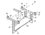
- the calibration jig 30 includes a first holding portion 31 and a second holding portion 32 that are provided along the mold 1 from the upper end to the inside of the mold 1 and hold the virtual level plate 40. These lower ends are connected by a connecting portion 33. Support members 34 and 35 suspended from the long side portion of the mold 1 are connected to the upper end of the first holding portion 31 and the upper end of the second holding portion 32, respectively. The support members 34 and 35 are provided with pins 36 for finely adjusting the level of the calibration jig 30.
- the first holding part 31 is formed with a holding groove 37 for holding the virtual level plate 40 at a predetermined pitch, for example, a 10 mm pitch, from the lower end of the detection head 11 to the measurement lower limit of the detection head 11.
- the second holding portion 32 is provided with holding pin insertion holes 38 at a pitch corresponding to the holding grooves 37 in the depth direction of the mold 1, and the holding pins 39 are inserted into the holding pin insertion holes 38. It is like that.
- These holding grooves 37, holding pin insertion holes 38, and holding pins 39 function as virtual level plate holding means.
- the virtual level plate 40 is held by the holding groove 37 at a predetermined position and the holding pin 39 (virtual level plate holding means) inserted into the holding pin insertion hole 38 corresponding thereto, and the mold at the position of the virtual level plate 40 is held.
- the output voltage E 0 of the feedback amplifier 4 of the inner bath level meter 20 is stored. Calibration is performed by performing this operation at all positions of a predetermined pitch.
- the virtual level plate holding means (holding groove 37 and holding pin insertion hole 38 and holding pin 39) are provided at each of the height positions divided by the predetermined interval pitches.
- a plurality of virtual level plates 40 having different sizes and having a gap of 1 mm or less between the long side of the mold 1 at the position are prepared, and calibration is performed using the corresponding virtual level plate 40 at each height position. .
- the gap between the virtual level plate 40 and the long side of the mold 1 can be 1 mm or less at any height position, and even a mold with a large taper is measured by the mold level meter 20 in the mold.
- the error of the hot water level signal can be reduced.
- the virtual level plate 40 having a gap with the long side of the mold 1 of 1 mm or less can be installed at any position provided at a predetermined pitch, for example, a 10 mm pitch.
- the output voltage of the amplifier 4 becomes a value close to the output voltage of the feedback amplifier 4 on the molten steel surface at the same position, and the distance from the lower end of the detection head 11 to the molten steel surface measured by the molten metal surface gauge 20 is from the lower end of the detection head 11. It can be a value close to the true distance to the molten steel surface. For this reason, the error of the hot water level signal measured by the hot water level meter 20 in the mold can be reduced.
- the holding groove 37 and the holding pin insertion hole 38 are provided in advance at a predetermined pitch, and the virtual level plate 40 is placed on the holding groove 37 and the 39 inserted into the holding pin insertion hole 38. It is easy to install the level plate 40 so as to be parallel to the lower surface of the detection head 11. Further, since the parallelism of the calibration jig 30 is finely adjusted by the pins 36, calibration can be performed with high accuracy.
- the present invention is not limited to the above embodiment and can be variously modified.
- the example in which the pitch of the virtual level plate holding means is 10 mm is shown, but the pitch is not limited to this.
- 39 inserted into the holding groove 37 and the holding pin insertion hole 38 is used as the virtual level plate holding means, any device may be used as long as the virtual level plate can be held at a predetermined pitch.
- a mold hot water meter having the same configuration as the mold hot water meter 20 and a calibration jig having the same structure as the calibration jig 30 are installed.
- FIG. 5 shows the relationship between the true distance and the sensor measurement value of the mold level gauge in comparison with the result when the conventional calibration method described with reference to FIG. 1 is used.
Landscapes
- Physics & Mathematics (AREA)
- General Physics & Mathematics (AREA)
- Engineering & Computer Science (AREA)
- Mechanical Engineering (AREA)
- Continuous Casting (AREA)
- Measurement Of Levels Of Liquids Or Fluent Solid Materials (AREA)
- Measurement Of Length, Angles, Or The Like Using Electric Or Magnetic Means (AREA)
Applications Claiming Priority (2)
| Application Number | Priority Date | Filing Date | Title |
|---|---|---|---|
| JP2012019118A JP2013154395A (ja) | 2012-01-31 | 2012-01-31 | モールド内湯面計の校正方法および校正治具 |
| JP2012-019118 | 2012-01-31 |
Publications (1)
| Publication Number | Publication Date |
|---|---|
| WO2013114916A1 true WO2013114916A1 (fr) | 2013-08-08 |
Family
ID=48904960
Family Applications (1)
| Application Number | Title | Priority Date | Filing Date |
|---|---|---|---|
| PCT/JP2013/050113 Ceased WO2013114916A1 (fr) | 2012-01-31 | 2013-01-08 | Procédé d'étalonnage et gabarit d'étalonnage de jauge de niveau d'eau chaude de moule |
Country Status (2)
| Country | Link |
|---|---|
| JP (1) | JP2013154395A (fr) |
| WO (1) | WO2013114916A1 (fr) |
Citations (3)
| Publication number | Priority date | Publication date | Assignee | Title |
|---|---|---|---|---|
| JPS61239120A (ja) * | 1985-04-16 | 1986-10-24 | Nippon Kokan Kk <Nkk> | 鋳造モールド湯面計 |
| JPH029832U (fr) * | 1988-07-05 | 1990-01-22 | ||
| JP2006192473A (ja) * | 2005-01-14 | 2006-07-27 | Nippon Steel Corp | 連続鋳造設備の鋳型内溶鋼レベル測定方法 |
-
2012
- 2012-01-31 JP JP2012019118A patent/JP2013154395A/ja not_active Withdrawn
-
2013
- 2013-01-08 WO PCT/JP2013/050113 patent/WO2013114916A1/fr not_active Ceased
Patent Citations (3)
| Publication number | Priority date | Publication date | Assignee | Title |
|---|---|---|---|---|
| JPS61239120A (ja) * | 1985-04-16 | 1986-10-24 | Nippon Kokan Kk <Nkk> | 鋳造モールド湯面計 |
| JPH029832U (fr) * | 1988-07-05 | 1990-01-22 | ||
| JP2006192473A (ja) * | 2005-01-14 | 2006-07-27 | Nippon Steel Corp | 連続鋳造設備の鋳型内溶鋼レベル測定方法 |
Also Published As
| Publication number | Publication date |
|---|---|
| JP2013154395A (ja) | 2013-08-15 |
Similar Documents
| Publication | Publication Date | Title |
|---|---|---|
| JP5463440B1 (ja) | モールド内湯面計の校正方法および校正治具 | |
| JPH09119857A (ja) | 電磁流量計 | |
| JP2016090524A (ja) | 電磁流量計の校正方法および校正システム | |
| CN105093138A (zh) | 磁场检测传感器及使用其的磁场检测装置 | |
| US4567435A (en) | Method and apparatus for continuously measuring distance utilizing eddy current and having temperature difference influence elimination | |
| JP5149562B2 (ja) | 非破壊測定方法及び非破壊測定装置 | |
| JP5293755B2 (ja) | 磁性体の複素透磁率測定装置およびこれを用いた磁性体の結晶粒径測定方法 | |
| RU2696909C1 (ru) | Способ и устройство для горячего измерения, во время прокатки, размера металлических профилей | |
| KR101470998B1 (ko) | 몰드내 탕면계의 교정 방법 및 교정 지그 | |
| WO2013114916A1 (fr) | Procédé d'étalonnage et gabarit d'étalonnage de jauge de niveau d'eau chaude de moule | |
| US10928178B2 (en) | Method and device for measuring the thickness of non-magnetisable layers on a magnetisable base material | |
| JP4736811B2 (ja) | 磁性体の複素透磁率測定装置の脚部間隔決定方法 | |
| JP3948594B2 (ja) | 鋼材のSi濃度測定方法 | |
| JP2005031014A (ja) | 磁気センサ | |
| JP2001264025A (ja) | ロール間距離の測定方法及び装置 | |
| JP4879518B2 (ja) | 渦電流を用いた加工深さの測定試験方法及びこれを用いた測定試験装置 | |
| JP6743130B2 (ja) | 圧延時に金属プロファイルのサイズを熱測定するためのデバイスおよび方法 | |
| JP2018080966A (ja) | 電磁流量計 | |
| US10060763B2 (en) | Sensor assembly for measuring the relative position of a control rod connected to a lead screw within a nuclear reactor | |
| US9804286B2 (en) | Method of optimising the output of a sensor for indicating the relative location of a mettalic object | |
| JP2014153093A (ja) | 電磁流速計の校正システム、校正係数の算出システム及びその方法 | |
| JP2005315732A (ja) | 強磁性体の変位測定装置 | |
| JP2005207755A (ja) | 電磁流量計 | |
| JP2014215082A (ja) | 測定装置及び測定方法 | |
| JPH08211085A (ja) | 流速測定装置 |
Legal Events
| Date | Code | Title | Description |
|---|---|---|---|
| 121 | Ep: the epo has been informed by wipo that ep was designated in this application |
Ref document number: 13743729 Country of ref document: EP Kind code of ref document: A1 |
|
| NENP | Non-entry into the national phase |
Ref country code: DE |
|
| 122 | Ep: pct application non-entry in european phase |
Ref document number: 13743729 Country of ref document: EP Kind code of ref document: A1 |