WO2013115373A1 - 加熱調理器 - Google Patents
加熱調理器 Download PDFInfo
- Publication number
- WO2013115373A1 WO2013115373A1 PCT/JP2013/052365 JP2013052365W WO2013115373A1 WO 2013115373 A1 WO2013115373 A1 WO 2013115373A1 JP 2013052365 W JP2013052365 W JP 2013052365W WO 2013115373 A1 WO2013115373 A1 WO 2013115373A1
- Authority
- WO
- WIPO (PCT)
- Prior art keywords
- tray
- heating chamber
- stopper
- stoppers
- heating
- Prior art date
- Legal status (The legal status is an assumption and is not a legal conclusion. Google has not performed a legal analysis and makes no representation as to the accuracy of the status listed.)
- Ceased
Links
Images


Classifications
-
- F—MECHANICAL ENGINEERING; LIGHTING; HEATING; WEAPONS; BLASTING
- F24—HEATING; RANGES; VENTILATING
- F24C—DOMESTIC STOVES OR RANGES ; DETAILS OF DOMESTIC STOVES OR RANGES, OF GENERAL APPLICATION
- F24C15/00—Details
- F24C15/16—Shelves, racks or trays inside ovens; Supports therefor
Definitions
- the present invention relates to a cooking device.
- a heating chamber having an opening on the front side, a heating chamber that can be taken in and out through the opening, a tray on which an object to be heated is mounted, and each side in the heating chamber are provided.
- the shelf holder extends from the vicinity of the opening on the front side of the heating chamber to the vicinity of the rear end wall of the heating chamber, and also serves to guide the tray into the heating chamber when the tray is placed in the heating chamber.
- the shelf holder when the tray is taken out from the inside of the heating chamber, the shelf holder is located on the lower side of the tray, so the front end of the shelf holder is hidden behind the tray and cannot be seen. As a result, there is a problem that the user accidentally pulls out the tray and drops the tray or the object to be heated on the tray.
- an object of the present invention is to provide a cooking device that can prevent the tray and the object to be heated from falling.
- the heating cooker of the present invention is A casing, A heating chamber provided in the casing and having an opening on the front side; A door that opens and closes the opening of the heating chamber; A tray that is provided so as to be able to be taken in and out of the heating chamber, and on which a heated object is mounted, Provided on the inner surface of the heating chamber, and a support portion for supporting the tray in the heating chamber; Provided on the inner surface of the heating cabinet, and a regulating portion that regulates the forward movement of the tray by contacting a part of the tray; When pulling out the tray from the inside of the heating chamber, the regulating portion with respect to a part of the tray is tilted in a direction different from the front in a state where the regulating portion is in contact with a part of the tray. Is released, and the tray can be pulled out of the heating chamber.
- the regulating portion abuts against a part of the tray before the entire tray comes out of the heating chamber, thereby restricting the forward movement of the tray. . Therefore, even if the front side of the support portion is not visible on the tray, it is possible to prevent the user from accidentally pulling out the tray and dropping the tray and the object to be heated.
- the restricting portion when pulling out the tray from the inside of the heating chamber, the restricting portion abuts against a part of the tray by tilting the tray in a direction different from the front in a state where the restricting portion is in contact with a part of the tray. Since the tray is released and can be pulled out of the heating chamber, the tray can be easily cleaned outside the heating chamber, and an object to be heated can be easily mounted on the tray.
- the restricting portion contacts the upper side of the tray and restricts the vertical rotation of the tray.
- the restricting portion abuts on the upper side of the tray and restricts the vertical rotation of the tray. Therefore, even if the user does not support the tray, the tray rotates by its own weight and falls down. Can be prevented.
- the tray can be prevented from rotating and falling due to its own weight, so the user can easily take out the object to be heated from the tray using both hands.
- the tray has a tray body and a first stopper provided on the tray body, A part of the tray is the first stopper.
- the restricting portion comes into contact with the first stopper provided in the tray body, so that the forward movement of the tray can be reliably restricted.
- the first stopper is provided on the lower surface of the tray body.
- the first stopper is provided on the lower surface of the tray, when the tray is viewed from above, the first stopper is not easily noticeable, and the deterioration of the aesthetics of the tray can be prevented.
- the first stopper includes a first end surface that comes into contact with the regulating portion when the tray is taken out from the heating chamber, and a second end surface that comes into sliding contact with the regulating portion when the tray is inserted into the heating chamber.
- Have The angle formed by the second end surface of the first stopper with respect to the tray insertion / removal direction is smaller than the angle formed by the first end surface of the first stopper with respect to the tray insertion / removal direction.
- the first end surface of the first stopper with respect to the tray insertion / removal direction is formed as compared with the angle formed by the second end surface of the first stopper with respect to the tray insertion / removal direction. Since the angle is large, the first end surface of the first stopper can come into contact with the restricting portion to restrict the movement of the tray.
- the angle formed by the second end surface of the first stopper with respect to the tray insertion / removal direction is smaller than the angle formed by the first end surface of the first stopper with respect to the tray insertion / removal direction.
- the second end surface of the first stopper is in sliding contact with the restricting portion, and the first stopper can get over the restricting portion. Therefore, the tray can be placed in the heating chamber relatively smoothly.
- the first stopper is provided on the upper surface of the tray body.
- the contact state of the restricting portion with respect to the first stopper can be easily recognized. Tilt operation becomes easier.
- the outer periphery of the tray has a substantially rectangular shape
- the first stopper is located at a corner portion on the rear side of the tray.
- the tray since the first stopper is located at the corner portion on the rear side of the tray, the tray can be tilted to reliably release the contact of the restricting portion with respect to the first stopper.
- the four corner portions of the tray have substantially the same shape.
- the four corner portions of the tray have substantially the same shape, so that it is not necessary to uniquely determine that the tray is placed in the heating chamber, and usability can be improved.
- the tray has a second stopper for positioning in the heating chamber.
- the tray can be positioned in the heating chamber by the second stopper, the target heating can be reliably performed on the object to be heated.
- the first stopper is provided integrally with the tray body.
- the first stopper is provided integrally with the tray body, the first stopper and the tray body can be obtained by integral molding. Therefore, the number of manufacturing steps of the tray can be reduced, and the manufacturing cost of the tray can be reduced.
- the restricting portion is located near the opening of the heating chamber.
- the restriction portion when the restriction portion is in contact with the first stopper to restrict the forward movement of the tray, the restriction portion is located in the vicinity of the opening of the heating chamber. The part can be protruded. Therefore, the object to be heated can be taken out from the tray more easily.
- the restricting portion includes a protruding portion positioned above the support portion and a protruding portion positioned forward of the support portion.
- the restricting portion includes the protruding portion positioned above the supporting portion and the protruding portion positioned in front of the supporting portion, so that the tray and the object to be heated are prevented from falling.
- the contact of the restricting portion is released by tilting the tray so that the near side of the tray is higher than the far side of the tray.
- the tray when the tray is mounted with an object to be heated, the tray is tilted so that the front side of the tray is higher than the back side of the tray, thereby releasing the contact of the restricting portion.
- the contact of the restricting portion is released, the heated object can be prevented from moving to the near side of the tray and falling from the tray.
- the cooking device of the present invention is provided in a casing, a heating chamber having an opening on the front side, a door that opens and closes the opening of the heating chamber, and a heating chamber that can be taken in and out.
- a tray on which an object to be heated is mounted; an inner surface of the heating chamber; a support portion that supports the tray in the heating chamber; an inner surface of the heating chamber; And a restricting portion that restricts the forward movement of the tray, so that the tray and the object to be heated can be prevented from falling.
- the restricting portion when pulling out the tray from the inside of the heating chamber, the restricting portion abuts against a part of the tray by tilting the tray in a direction different from the front in a state where the restricting portion is in contact with a part of the tray. Since the tray is released and can be pulled out of the heating chamber, the tray can be easily cleaned outside the heating chamber, and an object to be heated can be easily mounted on the tray.
- FIG. 1 is a front view of a heating cooker according to an embodiment of the present invention.
- FIG. 2 is a top view of the heating cooker with the handle door opened.
- FIG. 3 is a front view of the heating cooker with the handle door opened.
- FIG. 4 is a schematic cross-sectional view of the heating cooker.
- FIG. 5 is a perspective view of the heating cooker with the casing removed.
- FIG. 6 is a schematic view of the inside of the heating chamber of the heating cooker as viewed from the opening side.
- FIG. 7 is a schematic top view of a metal tray of the cooking device.
- FIG. 8 is a schematic right side view of the metal tray.
- FIG. 9 is a schematic left side view of the metal tray.
- FIG. 10 is a schematic top view of the glass tray of the cooking device.
- FIG. 1 is a front view of a heating cooker according to an embodiment of the present invention.
- FIG. 2 is a top view of the heating cooker with the handle door opened.
- FIG. 3
- FIG. 11 is a schematic right side view of the glass tray.
- FIG. 12 is a schematic left side view of the glass tray.
- FIG. 13 is a schematic view of the right side wall of the heating chamber as viewed from the inside.
- FIG. 14 is a schematic view of the left side wall of the heating chamber as viewed from the inside.
- FIG. 15 is a schematic diagram for explaining the operation at the time of taking out the metal tray.
- FIG. 16 is a schematic diagram for explaining the operation at the time of taking out the metal tray.
- FIG. 17 is a schematic diagram for explaining the operation at the time of taking out the metal tray.
- FIG. 18 is a schematic diagram for explaining the operation at the time of taking out the metal tray.
- FIG. 19 is a schematic diagram for explaining the operation when the metal tray is inserted.
- FIG. 20 is a schematic diagram for explaining the operation when the metal tray is inserted.
- FIG. 21 is a schematic diagram for explaining the operation at the time of taking out the glass tray.
- FIG. 22 is a schematic diagram for explaining the operation at the time of taking out the glass tray.
- FIG. 23 is a schematic diagram for explaining the operation at the time of taking out the glass tray.
- FIG. 24 is a schematic diagram for explaining the operation at the time of taking out the glass tray.
- FIG. 25 is a schematic diagram for explaining the operation at the time of taking out the glass tray.
- FIG. 26 is a schematic diagram for explaining the operation at the time of taking out the glass tray.
- FIG. 27 is a schematic diagram for explaining the operation when the glass tray is inserted.
- FIG. 28 is a schematic diagram for explaining the operation when the glass tray is inserted.
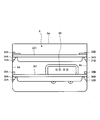
- FIG. 1 is a front view of a heating cooker according to an embodiment of the present invention.
- the heating cooker includes a casing 1 and a door 2 with a handle attached to the front side of the casing 1.
- a heat-resistant glass 5 is attached to the approximate center of the door 2 with a handle.
- An operation panel 3 is provided on the front side of the casing 1 so as to be adjacent to the door 2 with a handle when closed.
- a dew receptacle 4 is arranged below the door 2 with handle and the operation panel 3.
- the door with handle 2 is an example of a door.
- the operation panel 3 has a liquid crystal display unit 7, and the liquid crystal display unit 7 performs display according to the operation. Although not shown, the operation panel 3 is provided with a plurality of push buttons and the like.
- the dew receptacle 4 is a container that can be attached to and detached from the two front legs 6 and 6 provided on the front side of the bottom of the casing 1.
- the dew receiving device 4 is inserted into the lower side of the casing 1 from the front to the rear and attached to the front legs 6 and 6, the rear surface (rear surface) of the door 2 with the handle when the dew receiving device 4 is closed. Located below.
- FIG. 2 is a top view of a state where the door 2 with a handle of the heating cooker is fully opened (open state) as viewed from above.
- FIG. 3 is the front view (front view) which looked at the state which opened the door 2 with a handle of the said heating cooker from the front.
- a heating chamber 8 for heating the object to be heated 23 (see FIG. 4) is installed.
- the heating chamber 8 has an opening 8 a on the front side, and the opening 8 a is opened and closed by the lateral rotation of the door 2 with a handle.
- the side of the door with handle 2 opposite to the side of the operation panel 3 is rotatably attached to the side of the casing 1 opposite to the side of the operation panel 3 via a hinge (not shown). It has been.
- a latch hook 90 is provided on the rear surface of the door 2 with a handle. When the door with handle 2 is closed, the latch hook 90 is inserted into an insertion hole 91 provided at the peripheral edge of the opening 8a and is releasably locked to a latch mechanism (not shown) in the casing 1. . Further, the latch hook 90 can be unlocked by the user grasping the handle 2a of the door 2 with the handle.
- reference numeral 80 denotes a steam outlet from which steam generated by the steam generator 13 (see FIG. 5) blows out into the heating chamber 8.
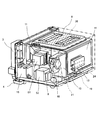
- FIG. 4 is a schematic cross-sectional view of the cooking device.
- a part of the air in the heating chamber 8 is discharged to the exhaust duct 100 through the exhaust port 8c and the exhaust tube 18, and is mixed with the air flowing from the cooling air inlet 101 in the exhaust duct 100 to be diluted. Is done.
- the air diluted in the exhaust duct 100 is blown out from the plurality of outlets 102 provided in the exhaust duct 100 toward one end of the dew receiving device 4.
- a part of the air flowing through the air passage 112 is blown out from the plurality of cooling air outlets 70 provided on the front surface side of the bottom plate of the casing 1 toward one end of the dew receiver 4.
- each intake port 17 is formed by a slit provided at the rear portion of the casing 1.
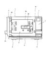
- FIG. 5 is a perspective view of the state where the casing 1 of the heating cooker is removed as viewed from the rear and obliquely upward.
- an electrical component chamber 9 is provided on the side of the heating chamber 8 (see FIGS. 3 and 4) and behind the operation panel 3, and on the side of the heating chamber 8 and behind the electrical component chamber 9.
- An intake space 10 is provided.
- a heater 26 for heating the object to be heated 23 is disposed in the upper space in the heating chamber 8.
- heat shield plates 11, 11,... are arranged above, below, behind, and on both sides of the heating chamber 8. That is, the heat shield plates 11, 11,... Are arranged around the opening 8 a of the heating chamber 8.
- a space between the heat shield plate 11 and the heating chamber 8 is filled with a heat insulating material (not shown).
- FIG. 5 the illustration of the heat shield plate above the heating chamber 8 is omitted.
- a steam generator 13 for generating steam is disposed on the rear side of the heating chamber 8.
- a water supply pump 19 connected to the steam generator 13 via a water supply tube (not shown) is disposed below the heating chamber 8.
- a tank storage unit 15 In the electrical component room 9, a tank storage unit 15, a magnetron 51, a power transformer 52 and the like for storing a water supply tank (not shown) are arranged.
- a water supply tank (not shown)
- Microwaves generated by the magnetron 51 are guided to the lower center of the heating chamber 8 through a waveguide (not shown) and directed upward in the heating chamber 8 while being stirred by a rotating antenna (not shown). And the object to be heated 23 is heated.
- the water in the water supply tank stored in the storage unit 15 is supplied to the steam generator 13 by a water supply pump 19 via a water supply tube (not shown).
- the steam generator 13 generates water vapor by heating water from the feed water pump 19 with a steam generating heater 24.
- the air outside the casing 1 flows into the intake space 10 from the plurality of intake ports 17 (see FIG. 4) as the cooling fan 16 is driven.
- the air in the intake space 10 is sent into the electrical component chamber 9 by the cooling fan 16.
- reference numeral 21 denotes a partition wall that partitions the electrical component chamber 9 and the intake space 10.
- a cooling fan 16 is attached to the partition wall 21.
- FIG. 6 is a schematic view of the inside of the heating chamber 8 viewed from the opening 8a.
- the metal tray 201 and the glass tray 301 can be taken in and out of the heating chamber 8.
- Upper shelf receivers 31A and 31B are provided above the inner surfaces of the right side wall 8d and the left side wall 8e of the heating chamber 8, and the upper shelf receivers 31A and 31B support the metal tray 201 from the lower side.
- lower shelf receivers 32A and 32B are provided below the inner surfaces of the right side wall 8d and the left side wall 8e of the heating chamber 8, and the lower shelf receivers 32A and 32B support the glass tray 301 from the lower side. .
- the metal tray 201 is supported by the upper shelf receivers 31A and 31B, the metal tray 201 is positioned at a height of, for example, about 23 cm from the installation surface of the heating cooker.
- the glass tray 301 when the glass tray 301 is supported by the lower shelf receivers 32A and 32B, the glass tray 301 is positioned at a height of, for example, about 15 cm from the installation surface of the heating cooker.
- the upper shelf supports 31A and 31B can also support the glass tray 301
- the lower shelf supports 32A and 32B can also support the metal tray 201.
- the metal tray 201 and the glass tray 301 are examples of trays.
- the upper shelf receivers 31A and 31B and the lower shelf receivers 32A and 32B are examples of a support portion.
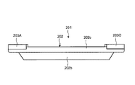
- FIG. 7 is a schematic top view of the metal tray 201 as viewed from above.
- FIG. 8 is a schematic right side view of the metal tray 201 as viewed from the right side.
- FIG. 9 is a schematic left side view of the metal tray 201 viewed from the left side.
- the metal tray 201 has a tray body 202 made of metal such as iron or stainless steel, and stoppers 203A, 203B, 203C, and 203D made of heat resistant resin.
- the periphery has a substantially rectangular shape. Further, the four corner portions of the metal tray 201 have substantially the same shape.
- the metal tray 201 is placed in the upper or lower part of the heating chamber 8 so that the stoppers 203A and 203B are located on the inner side of the heating chamber 8, or the stoppers 203C and 203D are placed on the inner side of the heating chamber 8. It can be put in the upper part or the lower part in the heating chamber 8 so as to be positioned.
- the stoppers 203A, 203B, 203C, and 203D are examples of first stoppers and examples of second stoppers.
- the tray main body 202 includes a bottom portion 202a on which the object to be heated 23 is mounted, a side portion 202b erected over the entire periphery of the peripheral portion of the bottom portion 202a, and a flange portion 202c connected to the upper end portion of the side portion 202b. It consists of.
- the bottom portion 202a is provided with a plurality of through holes 202d so that liquid such as water does not accumulate on the bottom portion 202a.
- the four corner portions of the flange portion 202c are shaped to draw an arc when viewed from above. That is, the outer peripheral edges of the four corner portions of the flange portion 202c are rounded.
- a pair located on the back side in the heating chamber 8 plays a role of regulating the movement of the metal tray 201 in the heating chamber 8
- the pair located on the near side in the heating chamber 8 plays a role of determining the position of the metal tray 201 in the heating chamber 8.
- the stoppers 203A, 203B, 203C, and 203D have a fan shape when viewed from above, and are disposed on the corner portion of the flange portion 202c and fixed with screws 203.
- the widths of the stoppers 203A, 203B, 203C, and 203D are slightly wider than the corners of the flange portion 202c, and a step is generated between the upper surfaces of the stoppers 203A, 203B, 203C, and 203D and the upper surface of the flange portion 202c. ing.
- the corner portions of the flange portion 202c are the upper surfaces of the upper shelf receivers 31A and 31B. It is supposed not to touch.
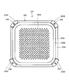
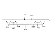
- FIG. 10 is a schematic top view of the glass tray 301 as viewed from above.
- FIG. 11 is a schematic right side view of the glass tray 301 viewed from the right side.
- FIG. 12 is a schematic left side view of the glass tray 301 as viewed from the left side.
- the glass tray 301 has a bottom portion 301a on which the object to be heated 23 is mounted, a right side portion 301b erected on the right edge portion of the bottom portion 301a, and a left edge portion of the bottom portion 301a. It has a standing left side portion 301c, a flat plate-like right end portion 301d continuous with the upper end portion of the right side portion 301b, and a flat plate-like left end portion 301e continuous with the upper end portion of the left side portion 301c.
- the bottom portion 301a is not provided with a through-hole, and a liquid such as water can be held by the bottom portion 301a.
- the outer peripheral edges of the four corner portions of the glass tray 301 are rounded.
- the glass tray 301 is placed in the upper or lower part of the heating chamber 8 so that stoppers 302A and 302B, which will be described later, are located on the back side in the heating chamber 8, or stoppers 302C and 302D which will be described later are placed in the heating chamber 8. It can be put in the upper part or the lower part in the heating chamber 8 so as to be located on the back side.
- the bottom portion 301a, the right side portion 301b, the left side portion 301c, the right end portion 301d, and the left end portion 301e are examples of the tray body.
- stoppers 302A and 302C having a trapezoidal shape when viewed from the side are provided on the lower surface of the right end portion 301d.
- the stopper 302A has a first inclined end face 303A on the stopper 302C side, and a second inclined end face 304A on the opposite side to the stopper 302C side.
- the stopper 302C also has a first inclined end face 303C on the stopper 302A side, and a second inclined end face 304C on the opposite side to the stopper 302A side.
- the inclination angles of the first inclined end surfaces 303A and 303C with respect to the lower surface of the right end portion 301d are larger than the inclination angles of the second inclined end surfaces 304A and 304C with respect to the lower surface of the right end portion 301d.
- the stoppers 302A and 302C are examples of first stoppers.
- the first inclined end surfaces 303A and 303C are examples of the first end surface.
- the second inclined end surfaces 304A and 304C are examples of the second end surface.
- stoppers 302B and 302D having a trapezoidal shape when viewed from the side are provided on the lower surface of the left end portion 301e.
- the stopper 302B has a first inclined end face 303B on the stopper 302D side, and a second inclined end face 304B on the opposite side to the stopper 302D side.
- the stopper 302D also has a first inclined end face 303D on the stopper 302B side, and a second inclined end face 304D on the opposite side to the stopper 302B side.
- the inclination angles of the first inclined end surfaces 303B and 303D with respect to the lower surface of the left end portion 301d are larger than the inclination angles of the second inclined end surfaces 304B and 304D with respect to the lower surface of the left end portion 301d.
- the stoppers 302B and 302D are examples of first stoppers.
- the first inclined end surfaces 303B and 303D are examples of the first end surface.
- the second inclined end surfaces 304B and 304D are examples of the second end surface.
- the stoppers 302A, 302B, 302C, 302D are convex portions protruding downward from the lower surface of the right end portion 301d or the left end portion 301e, and are a bottom portion 301a, a right side portion 301b, a left side portion 301c, a right end portion 301d, and a left end portion 301e. In addition, it is formed by integral molding using a heat-resistant glass material.
- the lower surface of the left end portion 301d is a surface that is substantially parallel to the direction in which the glass tray 301 is put in and out.
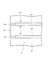
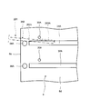
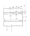
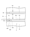
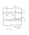
- FIG. 13 is a schematic view of the right side wall 8d of the heating chamber 8 as viewed from the inside.
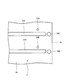
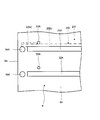
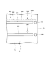
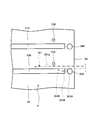
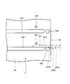
- FIG. 14 is the schematic diagram which looked at the left side wall 8e of the said heating chamber 8 from the inner side.
- the upper shelf receivers 31A, 31B and the lower shelf receivers 32A, 32B extend in a straight line from the vicinity of the opening 8a of the heating chamber 8 toward the rear portion of the heating chamber 6, as shown in FIGS. Further, the upper surfaces of the upper shelf receivers 31A and 31B and the upper surfaces of the lower shelf receivers 32A and 32B are inclined obliquely downward with respect to the horizontal direction.
- the flange 202c of the tray main body 202 of the metal tray 201 slides on the upper surfaces of the upper shelf receivers 31A and 31B.
- the right end portion 301d and the left end portion 301e of the glass tray 301 slide on the upper surfaces of the lower shelf supports 32A and 32B.
- first upper protrusions 33A and 33B positioned above the front end portions of the upper shelf receivers 31A and 31B are provided above the inner surfaces of the right side wall 8d and the left side wall 8e of the heating chamber 8, and the upper shelf receiver Cylindrical second upper protrusions 34A and 34B are provided in front of the front end portions of 31A and 31B.
- the first upper protrusions 33A and 33B and the second upper protrusions 34A and 34B are located in the vicinity of the opening 8a of the heating chamber 8.
- the diameters of the first upper protrusions 33A and 33B are smaller than the diameters of the second upper protrusions 34A and 34B.
- the upper ends of the second upper protrusions 34A and 34B are substantially the same height as the upper surfaces of the upper shelf supports 31A and 31B.
- the metal tray 201 when the metal tray 201 is pulled out from the heating chamber 8 by a preset length, even if the metal tray 201 tries to rotate under its own weight, the first upper protrusions 33A and 33B are not connected to the flange portion of the tray body 202. Abutting on the upper surface of 202c, the rotation of the metal tray 201 is also restricted.
- the first upper protrusions 33A and 33B and the second upper protrusions 34A and 34B are examples of restricting portions.
- first lower protrusions 35A and 35B are provided on the lower side of the inner surfaces of the right side wall 8d and the left side wall 8e of the heating chamber 8 positioned cylindrical first lower protrusions 35A and 35B positioned above the front end portions of the lower shelf receivers 32A and 32B.
- Cylindrical second lower protrusions 36A and 36B are provided in front of the front end portions of the lower shelf supports 32A and 32B.
- the first lower protrusions 35A and 35B and the second lower protrusions 36A and 36B are located in the vicinity of the opening 8a of the heating chamber 8.
- the diameters of the first lower protrusions 35A and 35B are smaller than the diameters of the second lower protrusions 36A and 36B.
- the upper ends of the second lower protrusions 36A and 36B are substantially the same height as the upper surfaces of the lower shelf supports 32A and 32B. Further, when the glass tray 301 with the stoppers 302A and 302B located behind the stoppers 302C and 302D is pulled out from the heating chamber 8 by moving in the horizontal direction, the glass tray 301 has a preset length from the heating chamber 8. When pulled out so far, the second lower protrusions 36A and 36B come into contact with the first inclined end surfaces 303A and 303B of the stoppers 302A and 302B, so that the horizontal movement of the glass tray 301 is restricted.
- the first lower protrusions 35 ⁇ / b> A and 35 ⁇ / b> B are positioned at the right end of the glass tray 301 even if the glass tray 301 tries to rotate by its own weight. In contact with the upper surface of 301d and the left end part 301e, rotation of the glass tray 301 is also restricted.
- the first lower protrusions 35A and 35B and the second lower protrusions 36A and 36B are examples of restricting portions.
- the stoppers 203A and 203B are placed on the back side (rear side) in the heating chamber 6 after the object to be heated 23 is placed on the bottom 202a of the tray body 202 of the metal tray 201.
- the metal tray 201 is placed in the upper part of the heating chamber 8 so that the metal tray 201 is supported by the upper shelf receivers 31A and 31B.
- the glass tray 301 is placed in the lower part of the heating chamber 8 so that the stoppers 302A and 302B are located on the back side (rear side) in the heating chamber 6, and the glass tray 301 is supported by the lower shelf receivers 32A and 32B.
- the first upper protrusions 33A and 33B come into contact with the front end surfaces of the stoppers 203A and 203B, and the metal tray 201 can be pulled out. Disappear. Thereby, even if the front end portions of the upper shelf receivers 31A and 31B are not visible on the metal tray 201, it is possible to prevent the user from accidentally pulling out the metal tray 201 and dropping the metal tray 201 and the object to be heated 23. .
- the metal tray 201 when the metal tray 201 is in the state of FIGS. 15 and 16, even if the metal tray 201 tries to rotate by its own weight around the second upper protrusions 34A and 34B, the first upper protrusions 33A and 33B The metal tray 201 can be prevented from rotating by contacting the upper surface of the flange portion 202c. Therefore, even if the user does not support the metal tray 201, the state in which most of the metal tray 201 has come out of the heating chamber 8 can be maintained. Therefore, in the above state, the user can freely use both hands, so that the object to be heated 23 can be easily taken out from the metal tray 201. For example, in the state of FIGS. 15 and 16, even if a weight of 2 kg is placed on the near side of the metal tray 201 and the hand is released from the metal tray 201, the metal tray 201 can be prevented from falling.
- the object to be heated 23 can be taken out in the state of FIGS. 15 and 16, the object to be heated 23 can be taken out without worrying about the place where the metal tray 201 is placed even in a small kitchen, for example. Can be improved.
- the first upper protrusions 33 ⁇ / b> A and 33 ⁇ / b> B are released from contact by tilting the metal tray 201. That is, the stoppers 203A and 203B are separated from the first upper protrusions 33A and 33B. Accordingly, the entire metal tray 201 can be taken out of the heating chamber 8 by passing the stoppers 203A and 203B under the first upper protrusions 33A and 33B. As a result, the metal tray 201 can be easily cleaned outside the heating chamber 8, and the article to be heated 23 can be easily placed on the bottom 202 a of the tray body 202.
- the stoppers 203A and 203B are on the flange portion 202c, the contact state of the first upper protrusions 33A and 33B with respect to the stoppers 203A and 203B can be easily seen. Therefore, the tilting operation of the metal tray 201 for releasing the contact of the first upper protrusions 33A and 33B can be easily performed.
- stoppers 203A and 203B are disposed on the corner portion of the flange portion 202c, the stoppers 203A and 203B can be reliably removed from the first upper protrusions 33A and 33B by tilting the metal tray 201.
- the metal tray 201 is stopped. The majority of the metal tray 201 can be reliably taken out of the heating chamber 8. Therefore, the heated object 23 can be taken out from the metal tray 201 more easily.
- the metal tray 201 when the metal tray 201 is placed in the upper part of the heating chamber 8 so that the stoppers 203A and 203B are located on the back side (rear side) in the heating chamber 6, as shown in FIGS. 2 By tilting the metal tray 201 around the upper protrusions 34A and 34B, the stoppers 203A and 203B are passed under the first upper protrusions 33A and 33B, and the metal tray 201 is pushed into the heating chamber 8. Then, as shown in FIGS. 19 and 20, the first upper protrusions 33A and 33B come into contact with the rear end surfaces of the stoppers 203C and 203D, and the metal tray 201 cannot be pushed into the heating chamber 8. As a result, since the metal tray 201 can be reliably disposed at a predetermined location, the target heating on the heated object 23 on the bottom portion 202a can be reliably performed.
- the second lower projections 36A and 36B are stoppers. It abuts on the second inclined end faces 304C and 304D of 302C and 302D.
- the second inclined end surfaces 304C and 304D of the stoppers 302C and 302D are brought into sliding contact with the second lower protrusions 36A and 36B, and the stoppers 302C and 302D are engaged with the second lower protrusions 36A and 36B. get over. Therefore, the glass tray 301 can be further pulled out from the heating chamber 8. Accordingly, the glass tray 301 can be pulled out from the heating chamber 8 relatively smoothly.
- the glass tray 301 When the glass tray 301 is further pulled out, as shown in FIGS. 23 and 24, when most of the glass tray 301 (for example, half or more) goes out of the heating chamber 8, the second lower protrusions 36A and 36B are The glass tray 301 cannot be pulled out by coming into contact with the first inclined end surfaces 303A and 303B of the stoppers 302A and 302B. Thereby, even if the front end portions of the lower shelf receivers 32A and 32 are not visible on the metal tray 201, it is possible to prevent the user from accidentally pulling out the glass tray 301 and dropping the glass tray 301.
- the glass tray 301 when the glass tray 301 is in the state of FIGS. 23 and 24, even if the glass tray 301 tries to rotate by its own weight around the second lower protrusions 36A and 36B, the first lower protrusions 35A and 35B Such rotation of the glass tray 301 can be prevented by contacting the upper surfaces of the right end portion 301d and the left end portion 301e. Therefore, even if the user does not support the glass tray 301, the state in which most of the glass tray 301 has come out of the heating chamber 8 can be maintained. Therefore, if the glass tray 301 has the object to be heated 23 mounted thereon, the user can easily take out the object to be heated 23 from the glass tray 301 in the above state. For example, in the state of FIGS. 23 and 24, even if a weight of 2 kg is placed on the near side of the glass tray 301 and the hand is released from the glass tray 301, the glass tray 301 can be prevented from falling.
- the object to be heated 23 can be taken out in the state of FIGS. 23 and 24, the object to be heated 23 can be taken out without worrying about the place where the glass tray 301 is placed even in a small kitchen, for example. Can be improved.
- the stoppers 302A and 302B are separated from the second lower protrusions 36A and 36B. Therefore, the stoppers 302A and 302B can get over the second upper protrusions 33A and 33B, and the entire glass tray 301 can be taken out of the heating chamber 8. As a result, the object to be heated 23 can be easily placed on the bottom 301 a of the glass tray 301, and the glass tray 301 can be easily cleaned outside the heating chamber 8.
- the first inclined end surfaces 303C and 303D of the stoppers 302C and 302D come into contact with each other, but the glass tray 301 is tilted as in FIGS. By doing so, the contact of the second lower protrusions 36A and 36B is released. That is, the stoppers 302C and 302D are separated from the second lower protrusions 36A and 36B. Therefore, the entire glass tray 301 can be put in the lower part of the heating chamber 6 by getting the stoppers 302C and 302D over the second lower protrusions 36A and 36B.
- the metal tray 201 can be used in an overlapping manner on the glass tray 301. Therefore, the convenience of the glass tray 301 can be improved.
- stoppers 302A and 302C are provided on the lower surface of the right end portion 301d, and the stoppers 302B and 302D are provided on the lower surface of the left end portion 301e. Therefore, when the glass tray 301 is viewed from above, the stoppers 302A, 302B and 302C are provided. , 302D is inconspicuous, and the deterioration of the aesthetic appearance of the glass tray 301 can be prevented.
- the stoppers 302A, 302B, 302C, and 302D are formed by integral molding using a heat-resistant glass material together with the bottom portion 301a, the right side portion 301b, the left side portion 301c, the right end portion 301d, the left end portion 301e, and the like.
- the manufacturing cost of the glass tray 301 can be reduced by reducing the number of manufacturing steps of the glass tray 301.
- the second lower protrusions 36A and 36B are located in the vicinity of the opening 8a of the heating chamber 8, the second lower protrusions 36A and 36B come into contact with the stoppers 302A and 302B so that the glass tray 301 is stopped. And most of the glass tray 301 can be reliably taken out of the heating chamber 8. Therefore, when the glass tray 301 has the object to be heated 23 mounted thereon, the object to be heated 23 can be taken out from the glass tray 301 more easily.
- the glass tray 301 is not provided with a stopper for determining the position in the heating chamber 8, but the glass tray 301 may be provided with a stopper for determining the position in the heating chamber 8. Good.
- the metal tray 201 is placed in the upper part of the heating chamber 8 so that the stoppers 203A and 203B are located on the inner side of the heating chamber 6, but the stoppers 203C and 203D are located in the inner side of the heating chamber 6.
- the metal tray 201 can also be placed in the upper part of the heating chamber 8 so as to be located on the side.
- the stoppers 203C and 203D are positioned on the inner side of the heating chamber 6
- the stoppers 203A and 203B are positioned on the inner side of the heating chamber 6.
- the glass tray 301 is placed in the lower part of the heating chamber 8 so that the stoppers 302A and 302B are located on the inner side of the heating chamber 6, but the stoppers 302C and 302D are disposed in the inner side of the heating chamber 6.
- the glass tray 301 can also be put in the lower part in the heating chamber 8 so that it may be located in the side.
- the stoppers 302C and 302D are located on the inner side of the heating chamber 6
- the stoppers 302A and 302B are located on the inner side of the heating chamber 6.
- the metal tray 201 is supported by the upper shelf receivers 31A and 31B, but the glass tray 301 can also be supported by the upper shelf receivers 31A and 31B.
- the same operation and effect as when the glass tray 301 is supported by the lower shelf receivers 32A and 32B can be obtained.
- the glass tray 301 is supported by the lower shelf receivers 32A and 32B, but the metal tray 201 can also be supported by the lower shelf receivers 32A and 32B.
- both the first upper protrusions 33A and 33B and the second upper protrusions 34A and 34B are provided on the inner surface of the heating chamber 8, but the first upper protrusions 33A and 33B and the second upper protrusion 33A and 34B are provided on the inner surface of the heating chamber 8. Only one of the upper protrusions 34A and 34B may be provided.
- both the first lower protrusions 35A and 35B and the second lower protrusions 36A and 36B are provided on the inner surface of the heating chamber 8, but the first lower protrusions 35A and 35B and the second lower projections 35A and 36B are provided on the inner surface of the heating chamber 8. Only one of the lower protrusions 36A and 36B may be provided.
- the contact of the first upper protrusions 33A and 33B with the front end surfaces of the stoppers 203A and 203B tilts the metal tray 201 so that the front side of the metal tray 201 is higher than the back side of the metal tray 201.
- the first upper protrusions 33 ⁇ / b> A and 33 ⁇ / b> A are released so as to be released by tilting the metal tray 201 so that the back side of the metal tray 201 is higher than the near side of the metal tray 201.
- the shape or position of 33B and stoppers 203A and 203B may be changed.
- the glass tray is such that the second lower protrusions 36A and 36B are in contact with the first inclined end surfaces 303A and 303B of the stoppers 302A and 302B so that the front side of the glass tray 301 is higher than the back side of the glass tray 301.
- the glass tray in order to be released by tilting the glass tray 301 so that the back side of the glass tray 301 is higher than the near side of the glass tray 301, it is released.
- the shape or position of the lower protrusions 36A and 36B and the stoppers 302A and 302B may be changed.
- the present invention can be applied not only to heating cookers such as ovens, ranges, and microwave ovens that use superheated steam or steam, but also to cookers such as ovens, ranges, and microwave ovens that do not use superheated steam and steam. .
Landscapes
- Engineering & Computer Science (AREA)
- Chemical & Material Sciences (AREA)
- Combustion & Propulsion (AREA)
- Mechanical Engineering (AREA)
- General Engineering & Computer Science (AREA)
- Electric Ovens (AREA)
- Baking, Grill, Roasting (AREA)
Description
本発明は加熱調理器に関する。
従来、加熱調理器としては、前側に開口部を有する加熱庫と、この開口部を通して加熱庫内に出し入れ可能に設けられ、被加熱物を搭載するトレイと、加熱庫内の各側面に設けられ、トレイを下側から支持する棚受けとを備えたものがある(例えば特開2011-163697号公報(特許文献1)参照)。
上記棚受けは、加熱庫の前側の開口部近傍から加熱庫の後端壁近傍まで延びており、上記加熱庫内にトレイを入れるとき、トレイを加熱庫内へ案内する役割も果たす。
ところが、上記加熱調理器では、加熱庫内からトレイを出すとき、棚受けがトレイの下側に位置するため、棚受けの前端部がトレイで隠れて見えない。その結果、ユーザがトレイを誤って引き出し過ぎて、トレイ、または、トレイ上の被加熱物を落下させてしまうという問題がある。
そこで、本発明の課題は、トレイや被加熱物の落下を防ぐことができる加熱調理器を提供することにある。
上記課題を解決するため、本発明の加熱調理器は、
ケーシングと、
上記ケーシング内に設けられ、前側に開口部を有する加熱庫と、
上記加熱庫の上記開口部を開閉する扉と、
上記加熱庫内に出し入れ可能に設けられて、被加熱物を搭載するトレイと、
上記加熱庫の内面に設けられ、上記加熱庫内で上記トレイを支持する支持部と、
上記加熱庫の内面に設けられて、上記トレイの一部と当接することで上記トレイの前方への移動を規制する規制部と
を備え、
上記加熱庫内から上記トレイを引き出す場合、上記規制部が上記トレイの一部に当接した状態で、上記トレイを前方とは異なる方向に傾動させることで、上記トレイの一部に対する上記規制部の当接が解除されて、上記トレイを上記加熱庫外に引き出せるようになっていることを特徴としている。
上記構成によれば、上記加熱庫内からトレイを引き出す場合、トレイの全部が加熱庫外に出る前に、規制部がトレイの一部に当接することで、トレイの前方への移動を規制する。したがって、上記支持部の前側がトレイで見えないとしても、ユーザがトレイを誤って引き出し過ぎて、トレイや被加熱物が落下するのを防ぐことができる。
また、上記加熱庫内からトレイを引き出す場合、規制部がトレイの一部に当接した状態で、トレイを前方とは異なる方向に傾動させることで、トレイの一部に対する規制部の当接が解除されて、トレイを加熱庫外に引き出せるようになっているので、トレイを加熱庫外で容易に清掃できるし、トレイに被加熱物を容易に搭載できる。
一実施形態の加熱調理器では、
上記規制部は上記トレイの上側に当接して上記トレイの鉛直方向の回動を規制する。
上記規制部は上記トレイの上側に当接して上記トレイの鉛直方向の回動を規制する。
上記実施形態によれば、上記規制部はトレイの上側に当接してトレイの鉛直方向の回動を規制するので、ユーザがトレイを支持しなくても、トレイが自重で回動して転倒するのを防ぐことができる。
また、ユーザがトレイを支持しなくても、トレイが自重で回動して転倒するのを防ぐことができるので、ユーザは両手を使ってトレイから被加熱物を容易に取り出すことができる。
一実施形態の加熱調理器では、
上記トレイは、トレイ本体と、上記トレイ本体に設けられた第1ストッパとを有し、
上記トレイの一部は上記第1ストッパである。
上記トレイは、トレイ本体と、上記トレイ本体に設けられた第1ストッパとを有し、
上記トレイの一部は上記第1ストッパである。
上記実施形態によれば、上記規制部が、トレイ本体に設けられた第1ストッパと当接するので、トレイの前方への移動を確実に規制できる。
一実施形態の加熱調理器では、
上記第1ストッパは上記トレイ本体の下面に設けられている。
上記第1ストッパは上記トレイ本体の下面に設けられている。
上記実施形態によれば、上記トレイの下面に第1ストッパを設けるので、トレイを上方から見たとき、第1ストッパが目立ち難く、トレイの美観の低下を防ぐことができる。
一実施形態の加熱調理器では、
上記第1ストッパは、上記加熱庫内から上記トレイを出す場合に上記規制部に当接する第1端面と、上記加熱庫内に上記トレイを入れる場合に上記規制部に摺接する第2端面とを有し、
上記トレイの出し入れ方向に対する上記第1ストッパの上記第1端面が成す角度に比べて、上記トレイの出し入れ方向に対する上記第1ストッパの上記第2端面が成す角度は小さい。
上記第1ストッパは、上記加熱庫内から上記トレイを出す場合に上記規制部に当接する第1端面と、上記加熱庫内に上記トレイを入れる場合に上記規制部に摺接する第2端面とを有し、
上記トレイの出し入れ方向に対する上記第1ストッパの上記第1端面が成す角度に比べて、上記トレイの出し入れ方向に対する上記第1ストッパの上記第2端面が成す角度は小さい。
上記実施形態によれば、上記加熱庫内からトレイを出す場合、トレイの出し入れ方向に対する第1ストッパの第2端面が成す角度に比べて、トレイの出し入れ方向に対する第1ストッパの第1端面が成す角度が大きいので、第1ストッパの第1端面が規制部に当接して、トレイの移動を規制することができる。一方、上記加熱庫内にトレイを入れる場合、トレイの出し入れ方向に対する第1ストッパの第1端面が成す角度に比べて、トレイの出し入れ方向に対する第1ストッパの第2端面が成す角度が小さいので、第1ストッパの第2端面が規制部に摺接して、第1ストッパは規制部を乗り越えることができる。したがって、上記トレイを加熱庫内に比較的スムーズに入れることができる。
一実施形態の加熱調理器では、
上記第1ストッパは上記トレイ本体の上面に設けられている。
上記第1ストッパは上記トレイ本体の上面に設けられている。
上記実施形態によれば、上記トレイ本体の上面に第1ストッパを設けることによって、第1ストッパに対する規制部の当接状態が視認し易くなるので、規制部の当接を解除するためのトレイの傾動操作がやり易くなる。
一実施形態の加熱調理器では、
上記トレイの外周縁は略矩形状を呈し、
上記第1ストッパは上記トレイの後側のコーナ部に位置する。
上記トレイの外周縁は略矩形状を呈し、
上記第1ストッパは上記トレイの後側のコーナ部に位置する。
上記実施形態によれば、上記第1ストッパがトレイの後側のコーナ部に位置するので、トレイを傾動をさせて、第1ストッパに対する規制部の当接を確実に解除することができる。
一実施形態の加熱調理器では、
上記トレイの4つのコーナ部は互いに略同じ形状を有する。
上記トレイの4つのコーナ部は互いに略同じ形状を有する。
上記実施形態によれば、上記トレイの4つのコーナ部は互いに略同じ形状を有するので、加熱庫内にトレイを入れる一意に決めなくてよく、使用性を向上させることができる。
一実施形態の加熱調理器では、
上記トレイは、上記加熱庫内で位置決めするための第2ストッパを有する。
上記トレイは、上記加熱庫内で位置決めするための第2ストッパを有する。
上記実施形態によれば、上記第2ストッパによってトレイを加熱庫内で位置決めできるので、被加熱物に目的とする加熱を確実に行うことができる。
一実施形態の加熱調理器では、
上記第1ストッパは上記トレイ本体と一体に設けられている。
上記第1ストッパは上記トレイ本体と一体に設けられている。
上記実施形態によれば、上記第1ストッパをトレイ本体と一体に設けるので、第1ストッパおよびトレイ本体を一体成型で得ることができる。したがって、上記トレイの製造工程数を減らして、トレイの製造コストを低減できる。
一実施形態の加熱調理器では、
上記規制部は上記加熱庫の上記開口部近傍に位置する。
上記規制部は上記加熱庫の上記開口部近傍に位置する。
上記実施形態によれば、上記規制部が第1ストッパと当接することでトレイの前方への移動を規制した時、規制部が加熱庫の開口部近傍に位置するので、加熱庫からトレイの大部分を突出させることができる。したがって、上記トレイから被加熱物をより容易に取り出すことができる。
一実施形態の加熱調理器では、
上記規制部は、上記支持部よりも上方に位置する突起部と、上記支持部よりも前方に位置する突起部とからなる。
上記規制部は、上記支持部よりも上方に位置する突起部と、上記支持部よりも前方に位置する突起部とからなる。
上記実施形態によれば、上記規制部は、支持部よりも上方に位置する突起部と、支持部よりも前方に位置する突起部とからなるので、トレイや被加熱物が落下するのを防ぐ効果と、トレイを加熱庫外で容易に清掃できる効果と、トレイに被加熱物を容易に搭載できる効果とが簡単な構造で得られる。
一実施形態の加熱調理器では、
上記規制部の当接は、上記トレイの手前側が上記トレイの奥側よりも高くなるように上記トレイを傾動させることで解除される。
上記規制部の当接は、上記トレイの手前側が上記トレイの奥側よりも高くなるように上記トレイを傾動させることで解除される。
上記実施形態によれば、上記トレイが被加熱物を搭載している場合、トレイの手前側がトレイの奥側よりも高くなるようにトレイを傾動させることで、規制部の当接を解除するので、規制部の当接を解除するときに、被加熱物がトレイの手前側に移動してトレイから転落するのを防ぐことができる。
本発明の加熱調理器は、ケケーシングと、ケーシング内に設けられ、前側に開口部を有する加熱庫と、加熱庫の上記開口部を開閉する扉と、加熱庫内に出し入れ可能に設けられて、被加熱物を搭載するトレイと、加熱庫の内面に設けられ、加熱庫内でトレイを支持する支持部と、加熱庫の内面に設けられて、トレイの一部と当接することで上記トレイの前方への移動を規制する規制部とを備えるので、トレイや被加熱物が落下するのを防ぐことができる。
また、上記加熱庫内からトレイを引き出す場合、規制部がトレイの一部に当接した状態で、トレイを前方とは異なる方向に傾動させることで、トレイの一部に対する規制部の当接が解除されて、トレイを加熱庫外に引き出せるようになっているので、トレイを加熱庫外で容易に清掃できるし、トレイに被加熱物を容易に搭載できる。
以下、本発明の加熱調理器を図示の実施の形態により詳細に説明する。
図1は本発明の一実施形態の加熱調理器の正面図である。
上記加熱調理器は、ケーシング1と、このケーシング1の前面側に取り付けられた把手付きドア2とを備えている。この把手付きドア2の略中央に耐熱ガラス5を取り付けている。また、ケーシング1の前面側には、閉鎖時の把手付きドア2と隣り合うように操作パネル3を設けている。そして、把手付きドア2と操作パネル3の下方には露受容器4を配置している。なお、把手付きドア2は扉の一例である。
上記操作パネル3は液晶表示部7を有し、この液晶表示部7が操作に応じた表示を行う。また、図示しないが、操作パネル3には、複数の押ボタンなどを設けている。
上記露受容器4は、ケーシング1の底部の前側に設けられた2つの前脚6,6に着脱可能な容器である。そして、露受容器4を前方から後方に向かってケーシング1の下側に挿入して前脚6,6に取り付けると、露受容器4の一部が閉鎖時の把手付きドア2の後面(裏面)の下方に位置する。
図2は、上記加熱調理器の把手付きドア2を全開にした状態(開放状態)を上方から見た上面図である。また、図3は、上記加熱調理器の把手付きドア2を全開にした状態を正面から見た正面図(前面図)である。
図2,図3に示すケーシング1内には、被加熱物23(図4参照)を加熱するための加熱庫8を設置している。加熱庫8は前面側に開口部8aに有し、この開口部8aは把手付きドア2の横方向の回動により開閉される。ここで、把手付きドア2において操作パネル3側とは反対側の側部は、ケーシング1において操作パネル3側とは反対側の側部にヒンジ(図示せず)を介して回動自在に取り付けられている。
上記把手付きドア2の後面にはラッチフック90を設けている。このラッチフック90は、把手付きドア2の閉鎖時、開口部8aの周縁部に設けられた挿通孔91に挿通され、ケーシング1内のラッチ機構(図示せず)に解除可能に係止される。また、ラッチフック90の係止の解除は、ユーザが把手付きドア2の把手2aを握ることで行える。
なお、図3において、80は、蒸気発生装置13(図5参照)で発生した蒸気が加熱庫8内に向かって吹き出す蒸気吹出口である。
図4は上記加熱調理器の模式断面図である。
上記加熱調理器では、ケーシング1外の空気が、冷却ファン16によって、複数の吸気口17を介してケーシング1内に吸い込まれる。この複数の吸気口17を介してケーシング1内に吸い込まれた空気の一部は、電装品室9を通過した後、給気ダンパ50が開いて開状態の複数の給気口8bから加熱庫8に流入する。一方、上記複数の吸気口17を介してケーシング1内に吸い込まれた空気の他の一部は、電装品室9を通過した後、ケーシング1の底部側に流れて加熱庫8の下側の風通路112を介して排気ダクト100の冷却空気入口101に流入する。
また、上記加熱庫8内の空気の一部は、排気口8cおよび排気チューブ18を介して排気ダクト100に排出されて、排気ダクト100内で冷却空気入口101から流入した空気と混合されて希釈される。この排気ダクト100内で希釈された空気は、排気ダクト100に設けられた複数の排出口102から、露受容器4の一方の端部内に向かって吹き出す。
ここで、上記風通路112を流れる空気の一部は、ケーシング1の底板の前面側に設けられた複数の冷却風吹出口70から、露受容器4の一方の端部内に向かって吹き出す。
なお、図4において、26は、被加熱物23を加熱するためのヒータである。また、各吸気口17はケーシング1の後部に設けられたスリットで構成されている。
図5は、上記加熱調理器のケーシング1を取り外した状態を後方かつ斜め上方から見た斜視図である。
上記ケーシング1内において、加熱庫8(図3,図4参照)の側方かつ操作パネル3の後方には電装品室9を設け、加熱庫8の側方かつ電装品室9の後方には吸気空間10を設けている。
上記加熱庫8内の上側の空間には、被加熱物23を加熱するためのヒータ26を配置している。
一方、上記加熱庫8外においては、加熱庫8の上方、下方、後方および両側方のそれぞれに、遮熱板11,11,…を配置している。つまり、遮熱板11,11,…は、加熱庫8の開口部8aを除く周囲に配置されている。また、遮熱板11と加熱庫8との間の空間には断熱材(図示せず)を充填している。なお、図5において、加熱庫8の上方の遮熱板の図示は省略している。
また、上記加熱庫8の後面側には、蒸気を発生する蒸気発生装置13を配置している。また、加熱庫8の下側には、蒸気発生装置13に給水チューブ(図示せず)を介して接続された給水ポンプ19を配置している。
上記電装品室9内には、給水タンク(図示せず)が収納されるタンク収納部15、マグネトロン51、電源トランス52などが配置されている。そして、被加熱物23の加熱時には、冷却ファン16からの冷却風が電装品室9内を流れ、マグネトロン51などの電装品を冷却できるようにしている。
上記マグネトロン51で発生したマイクロ波は、導波管(図示せず)を介して加熱庫8の下部中央に導かれ、回転アンテナ(図示せず)によって攪拌されながら加熱庫8内の上方に向かって放射されて被加熱物23を加熱する。
上記収納部15に収納された給水タンク内の水は、給水ポンプ19によって、給水チューブ(図示せず)を介して蒸気発生装置13に供給される。蒸気発生装置13は、給水ポンプ19からの水を蒸気発生用ヒータ24で加熱して、水蒸気を発生する。
上記吸気空間10には、冷却ファン16の駆動に伴い、ケーシング1外の空気が複数の吸気口17(図4参照)から流れ込む。そして、吸気空間10内の空気は冷却ファン16で電装品室9内に送られる。
なお、図5において、21は、電装品室9と吸気空間10とを仕切る間仕切壁である。この間仕切壁21に冷却ファン16を取り付けている。
図6は、上記開口部8aから加熱庫8内を見た模式図である。
上記加熱庫8内には金属トレイ201およびガラストレイ301が出し入れが可能になっている。加熱庫8の右側壁8d,左側壁8eの内面の上側には上棚受け31A,31Bを設けてあり、この上棚受け31A,31Bが金属トレイ201を下側から支持している。また、加熱庫8の右側壁8d,左側壁8eの内面の下側には下棚受け32A,32Bを設けてあり、この下棚受け32A,32Bがガラストレイ301を下側から支持している。金属トレイ201は、上棚受け31A,31Bに支持されているとき、加熱調理器の設置面から例えば23cmぐらいの高さに位置する。また、ガラストレイ301は、下棚受け32A,32Bに支持されているとき、加熱調理器の設置面から例えば15cmぐらいの高さに位置する。上棚受け31A,31Bはガラストレイ301も支持できるようになっていると共に、下棚受け32A,32Bは金属トレイ201も支持できるようになっている。なお、金属トレイ201,ガラストレイ301はトレイの一例である。また、上棚受け31A,31B,下棚受け32A,32Bは支持部の一例である。
図7は、上記金属トレイ201を上方から見た概略上面図である。また、図8は、上記金属トレイ201を右側方から見た概略右側面図である。また、図9は、上記金属トレイ201を左側方から見た概略左側面図である。
上記金属トレイ201は、図7~図9に示すように、例えば鉄やステンレスなどの金属から成るトレイ本体202と、耐熱性樹脂から成るストッパ203A,203B,203C,203Dとを有して、外周縁が略矩形状を呈している。また、金属トレイ201の4つのコーナ部は互いに略同じ形状となっている。また、金属トレイ201は、ストッパ203A,203Bを加熱庫8内の奥側に位置するように、加熱庫8内の上部または下部に入れたり、ストッパ203C,203Dを加熱庫8内の奥側に位置するように、加熱庫8内の上部または下部に入れたりすることができるようになっている。なお、ストッパ203A,203B,203C,203Dは、第1ストッパの一例であり、第2ストッパの一例でもある。
上記トレイ本体202は、被加熱物23を搭載する底部202aと、この底部202aの周縁部の全周に渡って立設された側部202bと、この側部202bの上端部に連なるフランジ部202cとから成っている。底部202aには複数の貫通孔202dを設けて、水などの液体が底部202a上に溜まらないようにしている。また、フランジ部202cの4つのコーナ部は上面視で円弧を描くような形状となっている。すなわち、フランジ部202cの4つのコーナ部の外周縁は丸みをおびている。
上記ストッパ203A,203Bのペアとストッパ203C,203Dのペアとのうち、加熱庫8内の奥側に位置するペアが、加熱庫8内での金属トレイ201の移動を規制する役割を担う一方、加熱庫8内の手前側に位置するペアが、加熱庫8内での金属トレイ201の位置を決める役割を担う。また、ストッパ203A,203B,203C,203Dは、上方から見た形状が扇形状となっていて、フランジ部202cのコーナ部上に配置されてネジ203で固定されている。また、ストッパ203A,203B,203C,203Dの幅はフランジ部202cのコーナ部の幅よりも少し広く、ストッパ203A,203B,203C,203Dの上面とフランジ部202cの上面との間には段差が生じている。また、上棚受け31A,31Bが金属トレイ201を下側から支持し、かつ、トレイ本体202bの底部202aが略水平になっているとき、フランジ部202cの各コーナ部は上棚受け31A,31Bの上面に接触しないようになっている。
図10は、上記ガラストレイ301を上方から見た概略上面図である。また、図11は、上記ガラストレイ301を右側方から見た概略右側面図である。また、図12は、上記ガラストレイ301を左側方から見た概略左側面図である。
上記ガラストレイ301は、図10に示すように、被加熱物23を搭載する底部301aと、この底部301aの右側の縁部に立設された右側部301bと、底部301aの左側の縁部に立設された左側部301cと、右側部301bの上端部に連なる平板形状の右端部301dと、左側部301cの上端部に連なる平板形状の左端部301eとを有している。この底部301aには貫通孔を設けておらず、水などの液体を底部301aで保持できるようにしている。また、ガラストレイ301の4つのコーナ部の外周縁は丸みをおびている。また、ガラストレイ301は、後述するストッパ302A,302Bを加熱庫8内の奥側に位置するように、加熱庫8内の上部または下部に入れたり、後述するストッパ302C,302Dを加熱庫8内の奥側に位置するように、加熱庫8内の上部または下部に入れたりすることができるようになっている。なお、底部301a,右側部301b,左側部301c,右端部301d,左端部301eはトレイ本体の一例である。
上記右端部301dの下面には、図11に示すように、側方から見た形状が台形状を呈するストッパ302A,302Cを設けている。ストッパ302Aは、ストッパ302C側に第1傾斜端面303Aを有する一方、ストッパ302C側とは反対側に第2傾斜端面304Aを有している。また、ストッパ302Aと同様に、ストッパ302Cも、ストッパ302A側に第1傾斜端面303Cを有する一方、ストッパ302A側とは反対側に第2傾斜端面304Cを有している。また、右端部301dの下面に対する第1傾斜端面303A,303Cの傾斜角は、右端部301dの下面に対する第2傾斜端面304A,304Cの傾斜角よりも大きくしている。なお、ストッパ302A,302C,は第1ストッパの一例である。また、第1傾斜端面303A,303Cは第1端面の一例である。また、第2傾斜端面304A,304Cは第2端面の一例である。
上記左端部301eの下面には、図12に示すように、側方から見た形状が台形状を呈するストッパ302B,302Dを設けている。ストッパ302Bは、ストッパ302D側に第1傾斜端面303Bを有する一方、ストッパ302D側とは反対側に第2傾斜端面304Bを有している。また、ストッパ302Bと同様に、ストッパ302Dも、ストッパ302B側に第1傾斜端面303Dを有する一方、ストッパ302B側とは反対側に第2傾斜端面304Dを有している。また、左端部301dの下面に対する第1傾斜端面303B,303Dの傾斜角は、左端部301dの下面に対する第2傾斜端面304B,304Dの傾斜角よりも大きくしている。なお、ストッパ302B,302Dは第1ストッパの一例である。また、第1傾斜端面303B,303Dは第1端面の一例である。また、第2傾斜端面304B,304Dは第2端面の一例である。
上記ストッパ302A,302Bのペアとストッパ302C,302Dのペアとのうち、加熱庫8内の奥側に位置するペアが、加熱庫8内での金属トレイ201の移動を規制する役割を担う。また、ストッパ302A,302B,302C,302Dは、右端部301dまたは左端部301eの下面から下方に突出する凸部であって、底部301a、右側部301b、左側部301c、右端部301dおよび左端部301eなどと共に、耐熱ガラス材料を用いた一体成型で形成されたものである。
なお、上記左端部301dの下面は、ガラストレイ301の出し入れ方向と略平行となる面である。
図13は、上記加熱庫8の右側壁8dを内側から見た模式図である。また、図14は、上記加熱庫8の左側壁8eを内側から見た模式図である。
上記上棚受け31A,31Bおよび下棚受け32A,32Bは、図13,図14に示すように、加熱庫8の開口部8a近傍から加熱庫6の後部に向かって一直線状に伸びている。また、上棚受け31A,31Bの上面と下棚受け32A,32Bの上面とは、水平方向に対して斜め下側に傾斜している。上棚受け31A,31Bの上面上では、金属トレイ201のトレイ本体202のフランジ部202cが摺動する。一方、下棚受け32A,32Bの上面上では、ガラストレイ301の右端部301d,左端部301eが摺動する。
また、上記加熱庫8の右側壁8d,左側壁8eの内面の上側には、上棚受け31A,31Bの前端部の上方に位置する円柱形状の第1上突起33A,33Bを設けると共に、上棚受け31A,31Bの前端部の前方に位置する円柱形状の第2上突起34A,34Bを設けている。この第1上突起33A,33Bおよび第2上突起34A,34Bは加熱庫8の開口部8a近傍に位置している。また、第1上突起33A,33Bの径は第2上突起34A,34Bの径よりも小さくなっている。また、第2上突起34A,34Bの上端は上棚受け31A,31Bの上面と略同じ高さとなっている。また、ストッパ203A,203Bがストッパ203C,203Dよりも奥側にある状態の金属トレイ201を水平方向の移動で加熱庫8内から引き出す場合、加熱庫8内から金属トレイ201が予め設定された長さだけ引き出されると、第1上突起33A,33Bがストッパ203A,203Bの前端面(開口部8a側の端面)に当接して、金属トレイ201の水平方向の移動が制限されるようになっている。また、加熱庫8内から金属トレイ201が予め設定された長さだけ引き出された状態において、金属トレイ201が自重で回動しようとしても、第1上突起33A,33Bがトレイ本体202のフランジ部202cの上面に当接して、金属トレイ201の回動が制限されるようにもなっている。なお、第1上突起33A,33Bおよび第2上突起34A,34Bは規制部の一例である。
また、上記加熱庫8の右側壁8d,左側壁8eの内面の下側には、下棚受け32A,32Bの前端部の上方に位置する円柱形状の第1下突起35A,35Bを設けると共に、下棚受け32A,32Bの前端部の前方に位置する円柱形状の第2下突起36A,36Bを設けている。この第1下突起35A,35Bおよび第2下突起36A,36Bは加熱庫8の開口部8a近傍に位置している。また、第1下突起35A,35Bの径は第2下突起36A,36Bの径よりも小さくなっている。また、第2下突起36A,36Bの上端は下棚受け32A,32Bの上面と略同じ高さとなっている。また、ストッパ302A,302Bがストッパ302C,302Dよりも奥側にある状態のガラストレイ301を水平方向の移動で加熱庫8内から引き出す場合、加熱庫8内からガラストレイ301が予め設定された長さだけ引き出されると、第2下突起36A,36Bがストッパ302A,302Bの第1傾斜端面303A,303Bに当接して、ガラストレイ301の水平方向の移動が制限されるようになっている。また、加熱庫8内からガラストレイ301が予め設定された長さだけ引き出された状態において、ガラストレイ301が自重で回動しようとしても、第1下突起35A,35Bがガラストレイ301の右端部301d,左端部301eの上面に当接して、ガラストレイ301の回動が制限されるにようにもなっている。なお、第1下突起35A,35Bおよび第2下突起36A,36Bは規制部の一例である。
上記構成の加熱調理器で例えば蒸し料理をする場合、金属トレイ201のトレイ本体202の底部202a上に被加熱物23を置いた後、ストッパ203A,203Bが加熱庫6内の奥側(後側)に位置するように、金属トレイ201を加熱庫8内の上部に入れ、上棚受け31A,31Bに金属トレイ201を支持させる。これと共に、ストッパ302A,302Bが加熱庫6内の奥側(後側)に位置するように、ガラストレイ301を加熱庫8内の下部に入れ、下棚受け32A,32Bにガラストレイ301を支持させる。そして、把手付きドア2を閉じて、操作パネル3の複数の押ボタンを操作して、被加熱物23を蒸す。このとき、金属トレイ201上で生じた結露水などは、トレイ本体202の底部202aの複数の貫通孔202dから滴下して、ガラストレイ301の底部202a上に溜まる。
このようにして、上記被加熱物23を蒸した後、加熱庫8内から被加熱物23を取り出すために、把手付きドア2を開いて、金属トレイ201を引き出す場合、図15,図16に示すように、金属トレイ201の大部分(例えば半分以上)が加熱庫8外に出た時、第1上突起33A,33Bがストッパ203A,203Bの前端面に当接して、金属トレイ201が引き出せなくなる。これにより、上棚受け31A,31Bの前端部が金属トレイ201で見えなくても、ユーザが金属トレイ201を誤って引き出し過ぎて、金属トレイ201および被加熱物23が落下するのを防ぐことができる。
また、上記金属トレイ201が図15,図16の状態になった時、金属トレイ201が第2上突起34A,34B付近を中心に自重で回動しようとしても、第1上突起33A,33Bがフランジ部202cの上面に当接して、そのような金属トレイ201の回動を防ぐことができる。したがって、ユーザが金属トレイ201を支持しなくても、金属トレイ201の大部分が加熱庫8外に出た状態を保持できる。したがって、上記状態において、ユーザは両手を自由に使えるので、金属トレイ201から被加熱物23を容易に取り出すことができる。例えば、図15,図16の状態において、金属トレイ201の手前側に2kgの重りを乗せて、金属トレイ201から手を離しても、金属トレイ201の転倒を防ぐことができる。
また、図15,図16の状態で被加熱物23の取り出しができることによって、例えば狭いキッチンであっても、金属トレイ201の置き場所を気にせずに被加熱物23を取り出せるので、使用性を向上させることができる。
また、図17,図18に示すように、金属トレイ201を傾動させることにより、第1上突起33A,33Bの当接が解除される。つまり、第1上突起33A,33Bからストッパ203A,203Bが離間する。したがって、ストッパ203A,203Bに第1上突起33A,33Bの下をくぐらせて、金属トレイ201の全部を加熱庫8外に出すことができる。その結果、金属トレイ201を加熱庫8外で容易に清掃できるし、トレイ本体202の底部202a上に被加熱物23を容易に置くこともできる。
また、上記ストッパ203A,203Bがフランジ部202c上にあるので、ストッパ203A,203Bに対する第1上突起33A,33Bの当接状態が視認し易くなる。したがって、第1上突起33A,33Bの当接を解除するための金属トレイ201の傾動操作を容易に行うことができる。
また、上記フランジ部202cのコーナ部上にストッパ203A,203Bを配置しているので、金属トレイ201を傾動させて、第1上突起33A,33Bからストッパ203A,203Bを確実に外すことができる。
また、上記第1上突起33A,33Bは加熱庫8の開口部8a近傍に位置しているので、第1上突起33A,33Bがストッパ203A,203Bに当接することで金属トレイ201が止まった時、金属トレイ201の大部分を加熱庫8外に確実に出すことができる。したがって、金属トレイ201から被加熱物23をより容易に取り出すことができる。
また、上記ストッパ203A,203Bが加熱庫6内の奥側(後側)に位置するように、金属トレイ201を加熱庫8内の上部に入れる場合、図17,図18に示すように、第2上突起34A,34Bを中心に金属トレイ201を傾動させることにより、ストッパ203A,203Bに第1上突起33A,33Bの下をくぐらせて、金属トレイ201を加熱庫8内に押し込む。そうすると、図19,図20に示すように、第1上突起33A,33Bがストッパ203C,203Dの後端面に当接して、金属トレイ201を加熱庫8内に押し込むことができなくなる。その結果、金属トレイ201を予め定めた場所に確実に配置できるので、底部202a上の被加熱物23に目的とする加熱を確実に行うことができる。
一方、上記ガラストレイ301を引き出す場合、図21,図22に示すように、ガラストレイ301の一部(例えば半分未満)が加熱庫8外に出た時、第2下突起36A,36Bがストッパ302C,302Dの第2傾斜端面304C,304Dに当接する。この状態で、ガラストレイ301をさらに引くと、ストッパ302C,302Dの第2傾斜端面304C,304Dが第2下突起36A,36Bに摺接して、ストッパ302C,302Dが第2下突起36A,36Bを乗り越える。したがって、ガラストレイ301を加熱庫8内からさらに引き出すことができる。したがって、ガラストレイ301を加熱庫8内から比較的スムーズに引き出すことができる。
また、上記ガラストレイ301をさらに引き出す場合、図23,図24に示すように、ガラストレイ301の大部分(例えば半分以上)が加熱庫8外に出た時、第2下突起36A,36Bがストッパ302A,302Bの第1傾斜端面303A,303Bに当接して、ガラストレイ301が引き出せなくなる。これにより、下棚受け32A,32の前端部が金属トレイ201で見えなくても、ユーザがガラストレイ301を誤って引き出し過ぎて、ガラストレイ301が落下するのを防ぐことができる。
また、上記ガラストレイ301が図23,図24の状態になった時、ガラストレイ301が第2下突起36A,36B付近を中心に自重で回動しようとしても、第1下突起35A,35Bが右端部301d,左端部301eの上面に当接して、そのようなガラストレイ301の回動を防ぐことができる。したがって、ユーザがガラストレイ301を支持しなくても、ガラストレイ301の大部分が加熱庫8外に出た状態を保持できる。したがって、ガラストレイ301が被加熱物23を搭載しているなら、ユーザは上記状態のままでガラストレイ301から被加熱物23を容易に取り出すことができる。例えば、図23,図24の状態において、ガラストレイ301の手前側に2kgの重りを乗せて、ガラストレイ301から手を離しても、ガラストレイ301の転倒を防ぐことができる。
また、図23,図24の状態のままで被加熱物23の取り出しができることによって、例えば狭いキッチンであっても、ガラストレイ301の置き場所を気にせずに被加熱物23を取り出せるので、使用性を向上させることができる。
また、図25,図26に示すように、ガラストレイ301を傾動させることにより、第2下突起36A,36Bの当接が解除される。つまり、第2下突起36A,36Bからストッパ302A,302Bが離間する。したがって、ストッパ302A,302Bに第2上突起33A,33Bを乗り越えさせて、ガラストレイ301の全部を加熱庫8外に出すことができる。その結果、ガラストレイ301の底部301a上に被加熱物23を容易に置くことができると共に、ガラストレイ301を加熱庫8外で容易に清掃できる。
また、上記ストッパ302A,302Bが加熱庫6内の奥側(後側)に位置するように、ガラストレイ301を加熱庫8内の下部に入れる場合、図27,図28に示すように、第2下突起36A,36Bがストッパ302A,302Bの第2傾斜端面304A,304Bに当接する。この状態で、ガラストレイ301をさらに押すと、ストッパ302A,302Bの第2傾斜端面304A,304Bが第2下突起36A,36Bに摺接して、ストッパ302A,302Bが第2下突起36A,36Bを乗り越える。したがって、ガラストレイ301を加熱庫8内にさらに入れることができる。したがって、ガラストレイ301を加熱庫8内に比較的スムーズに入れることができる。
また、上記ストッパ302A,302Bが第2下突起36A,36Bを乗り越えた後、ストッパ302C,302Dの第1傾斜端面303C,303Dが当接するが、図25,図26と同様にガラストレイ301を傾動させることにより、第2下突起36A,36Bの当接が解除される。つまり、第2下突起36A,36Bからストッパ302C,302Dが離間する。したがって、ストッパ302C,302Dに第2下突起36A,36Bを乗り越えさせて、ガラストレイ301の全部を加熱庫6内の下部に入れることができる。
また、上記右端部301dの下面にストッパ302A,302Cを設け、かつ、左端部301eの下面にストッパ302B,302Dを設けているので、ガラストレイ301上に例えば金属トレイ201を重ねて使用できる。したがって、ガラストレイ301の利便性を向上させることができる。
また、上記右端部301dの下面にストッパ302A,302Cを設け、かつ、左端部301eの下面にストッパ302B,302Dを設けているので、ガラストレイ301を上方から見たとき、ストッパ302A,302B,302C,302Dが目立ち難く、ガラストレイ301の美観の低下を防ぐことができる。
また、上記ストッパ302A,302B,302C,302Dは、底部301a、右側部301b、左側部301c、右端部301dおよび左端部301eなどと共に、耐熱ガラス材料を用いた一体成型で形成されたものであるので、ガラストレイ301の製造工程数を減らして、ガラストレイ301の製造コストを低減できる。
また、上記第2下突起36A,36Bは加熱庫8の開口部8a近傍に位置しているので、第2下突起36A,36Bがストッパ302A,302Bに当接することでガラストレイ301が止まった時、ガラストレイ301の大部分を加熱庫8外に確実に出すことができる。したがって、ガラストレイ301が被加熱物23を搭載している場合、ガラストレイ301から被加熱物23をより容易に取り出すことができる。
上記実施形態では、ガラストレイ301に、加熱庫8内での位置を決めるためのストッパを設けていなかったが、ガラストレイ301に、加熱庫8内での位置を決めるためのストッパを設けてもよい。
上記実施形態では、ストッパ203A,203Bが加熱庫6内の奥側に位置するように、金属トレイ201を加熱庫8内の上部に入れていたが、ストッパ203C,203Dが加熱庫6内の奥側に位置するように、金属トレイ201を加熱庫8内の上部に入れることもできる。
また、上記ストッパ203C,203Dが加熱庫6内の奥側に位置するように、金属トレイ201を加熱庫8内の上部に入れる場合も、ストッパ203A,203Bが加熱庫6内の奥側に位置するように、金属トレイ201を加熱庫8内の上部に入れる場合と同様の作用効果が得られる。
上記実施形態では、ストッパ302A,302Bが加熱庫6内の奥側に位置するように、ガラストレイ301を加熱庫8内の下部に入れていたが、ストッパ302C,302Dが加熱庫6内の奥側に位置するように、ガラストレイ301を加熱庫8内の下部に入れることもできる。
また、上記ストッパ302C,302Dが加熱庫6内の奥側に位置するように、ガラストレイ301を加熱庫8内の下部に入れた場合も、ストッパ302A,302Bが加熱庫6内の奥側に位置するように、ガラストレイ301を加熱庫8内の下部に入れた場合と同様の作用効果が得られる。
上記実施形態では、上棚受け31A,31Bに金属トレイ201を支持させていたが、上棚受け31A,31Bにガラストレイ301を支持させることもできる。
また、上記上棚受け31A,31Bにガラストレイ301を支持させる場合も、下棚受け32A,32Bにガラストレイ301を支持させる場合と同様の作用効果が得られる。
上記実施形態では、下棚受け32A,32Bにガラストレイ301を支持させていたが、下棚受け32A,32Bに金属トレイ201を支持させることもできる。
また、上記下棚受け32A,32Bに金属トレイ201を支持させる場合も、下棚受け32A,32Bにガラストレイ301を支持させる場合と同様の作用効果が得られる。
上記実施形態では、加熱庫8の内面に第1上突起33A,33Bおよび第2上突起34A,34Bの両方を設けていたが、加熱庫8の内面に第1上突起33A,33Bおよび第2上突起34A,34Bの一方だけを設けるようにしてもよい。
上記実施形態では、加熱庫8の内面に第1下突起35A,35Bおよび第2下突起36A,36Bの両方を設けていたが、加熱庫8の内面に第1下突起35A,35Bおよび第2下突起36A,36Bの一方だけを設けるようにしてもよい。
上記実施形態では、ストッパ203A,203Bの前端面に対する第1上突起33A,33Bの当接は、金属トレイ201の手前側が金属トレイ201の奥側よりも高くなるように金属トレイ201を傾動させることで解除されるようにしていたが、例えば、金属トレイ201の奥側が金属トレイ201の手前側よりも高くなるように金属トレイ201を傾動させることで解除されるように、第1上突起33A,33B,ストッパ203A,203Bの形状または位置などを変更してもよい。
上記実施形態では、ストッパ302A,302Bの第1傾斜端面303A,303Bに対する第2下突起36A,36Bの当接は、ガラストレイ301の手前側がガラストレイ301の奥側よりも高くなるようにガラストレイ301を傾動させることで解除されるようにしていたが、例えば、ガラストレイ301の奥側がガラストレイ301の手前側よりも高くなるようにガラストレイ301を傾動させることで解除されるように、第2下突起36A,36B,ストッパ302A,302Bの形状または位置などを変更してもよい。
本発明は、例えば、過熱水蒸気または水蒸気を使用するオーブン、レンジ、オーブンレンジ等の加熱調理器のみならず、過熱水蒸気および水蒸気を使用しないオーブン、レンジ、オーブンレンジ等の加熱調理器にも適用できる。
1…ケーシング
2…把手付きドア
8…加熱庫
8a…開口部
8b…給気口
8c…排気口
8d…右側壁
8e…左側壁
23…被加熱物
31A,31B…上棚受け
32A,32B…下棚受け
33A,33B…第1上突起
34A,34B…第2上突起
35A,35B…第1下突起
36A,36B…第2下突起
201…金属トレイ
202…トレイ本体
202a…底部
202b…側部
202c…フランジ部
202d…貫通孔
203A,203B,203C,203D…ストッパ
301…ガラストレイ
301a…底部
301b…右側部
301c…左側部
301d…右端部
301e…左端部
302A,302B,302C,302D…ストッパ
303A,303B,303C,303D…第1傾斜端面
304A,304B,304C,304D…第2傾斜端面
Claims (11)
- ケーシング(1)と、
上記ケーシング(1)内に設けられ、前側に開口部(8a)を有する加熱庫(8)と、
上記加熱庫(8)の上記開口部(8a)を開閉する扉(2)と、
上記加熱庫(8)内に出し入れ可能に設けられて、被加熱物(23)を搭載するトレイ(201,301)と、
上記加熱庫(8)の内面に設けられ、上記加熱庫(8)内で上記トレイ(201,301)を支持する支持部(31A,31B,32A,32B)と、
上記加熱庫(8)の内面に設けられて、上記トレイ(201,301)の一部と当接することで上記トレイ(201,301)の前方への移動を規制する規制部(33A,33B,34A,34B,35A,35B,36A,36B)と
を備え、
上記加熱庫(8)内から上記トレイ(201,301)を引き出す場合、上記規制部(33A,33B,34A,34B,35A,35B,36A,36B)が上記トレイ(201,301)の一部に当接した状態で、上記トレイ(201,301)を前方とは異なる方向に傾動させることで、上記トレイ(201,301)の一部に対する上記規制部(33A,33B,34A,34B,35A,35B,36A,36B)の当接が解除されて、上記トレイ(201,301)を上記加熱庫(8)外に引き出せるようになっていることを特徴とする加熱調理器。 - 請求項1に記載の加熱調理器において、
上記規制部(33A,33B,34A,34B,35A,35B,36A,36B)は上記トレイ(201,301)の上側に当接して上記トレイ(201,301)の鉛直方向の回動を規制することを特徴とする加熱調理器。 - 請求項1または2に記載の加熱調理器において、
上記トレイ(201,301)は、トレイ本体(201,301a,301b,301c,301d,301e)と、上記トレイ本体(301a,301b,301c,301d,301e)に設けられた第1ストッパ(203A,203B,203C,203D,302A,302B,302C,302D)とを有し、
上記トレイ(201,301)の一部は上記第1ストッパ(203A,203B,203C,203D,302A,302B,302C,302D)であることを特徴とする加熱調理器。 - 請求項3に記載の加熱調理器において、
上記第1ストッパ(302A,302B,302C,302D)は上記トレイ本体(301a,301b,301c,301d,301e)の下面に設けられていることを特徴とする加熱調理器。 - 請求項4に記載の加熱調理器において、
上記第1ストッパ(302A,302B,302C,302D)は、上記加熱庫(8)内から上記トレイ(301)を出す場合に上記規制部(33A,33B,34A,34B,35A,35B,36A,36B)に当接する第1端面(303A,303B,303C,303D)と、上記加熱庫(8)内に上記トレイ(301)を入れる場合に上記規制部(33A,33B,34A,34B,35A,35B,36A,36B)に摺接する第2端面(304A,304B,304C,304D)とを有し、
上記トレイ(301)の出し入れ方向に対する上記第1ストッパ(302A,302B,302C,302D)の上記第1端面(303A,303B,303C,303D)が成す角度に比べて、上記トレイ(301)の出し入れ方向に対する上記第1ストッパ(302A,302B,302C,302D)の上記第2端面(304A,304B,304C,304D)が成す角度は小さいことを特徴とする加熱調理器。 - 請求項3に記載の加熱調理器において、
上記第1ストッパ(203A,203B,203C,203D,302A,302B,302C,302D)は上記トレイ本体(202)の上面に設けられていることを特徴とする加熱調理器。 - 請求項6に記載の加熱調理器において、
上記トレイ(201)の外周縁は略矩形状を呈し、
上記第1ストッパ(203A,203B,203C,203D)は上記トレイ(201,301)の後側のコーナ部に位置することを特徴とする加熱調理器。 - 請求項7に記載の加熱調理器において、
上記トレイ(201)の4つのコーナ部は互いに略同じ形状を有することを特徴とする加熱調理器。 - 請求項6から8までのいずれか一項に記載の加熱調理器において、
上記トレイ(201)は、上記加熱庫(8)内で位置決めするための第2ストッパ(203A,203B,203C,203D)を有することを特徴とする加熱調理器。 - 請求項3から9までのいずれか一項に記載の加熱調理器において、
上記第1ストッパ(203A,203B,203C,203D)は上記トレイ本体(202)と一体に設けられていることを特徴とする加熱調理器。 - 請求項1から10までのいずれか一項に記載の加熱調理器において、
上記規制部(33A,33B,34A,34B,35A,35B,36A,36B)は上記加熱庫(8)の上記開口部(8a)近傍に位置することを特徴とする加熱調理器。
Priority Applications (1)
| Application Number | Priority Date | Filing Date | Title |
|---|---|---|---|
| EP13743452.8A EP2811231A4 (en) | 2012-02-02 | 2013-02-01 | COOKER |
Applications Claiming Priority (2)
| Application Number | Priority Date | Filing Date | Title |
|---|---|---|---|
| JP2012-020632 | 2012-02-02 | ||
| JP2012020632A JP2013160403A (ja) | 2012-02-02 | 2012-02-02 | 加熱調理器 |
Publications (1)
| Publication Number | Publication Date |
|---|---|
| WO2013115373A1 true WO2013115373A1 (ja) | 2013-08-08 |
Family
ID=48905400
Family Applications (1)
| Application Number | Title | Priority Date | Filing Date |
|---|---|---|---|
| PCT/JP2013/052365 Ceased WO2013115373A1 (ja) | 2012-02-02 | 2013-02-01 | 加熱調理器 |
Country Status (3)
| Country | Link |
|---|---|
| EP (1) | EP2811231A4 (ja) |
| JP (1) | JP2013160403A (ja) |
| WO (1) | WO2013115373A1 (ja) |
Families Citing this family (1)
| Publication number | Priority date | Publication date | Assignee | Title |
|---|---|---|---|---|
| JP2018056004A (ja) * | 2016-09-29 | 2018-04-05 | パナソニックIpマネジメント株式会社 | 誘導加熱調理器 |
Citations (4)
| Publication number | Priority date | Publication date | Assignee | Title |
|---|---|---|---|---|
| JPS52102964U (ja) * | 1976-02-02 | 1977-08-04 | ||
| JPS55140912U (ja) * | 1979-03-28 | 1980-10-08 | ||
| JPH06209865A (ja) * | 1993-01-20 | 1994-08-02 | Matsushita Electric Ind Co Ltd | 加熱調理器 |
| JP2011163697A (ja) | 2010-02-12 | 2011-08-25 | Panasonic Corp | マイクロ波加熱調理器 |
Family Cites Families (5)
| Publication number | Priority date | Publication date | Assignee | Title |
|---|---|---|---|---|
| US1974830A (en) * | 1932-07-15 | 1934-09-25 | American Stove Co | Rack or slide for cooking stoves or the like |
| US2466360A (en) * | 1945-12-15 | 1949-04-05 | Union Steel Prod Co | Rack assembly for refrigerators, ovens, and the like |
| JPH0476317A (ja) * | 1990-07-16 | 1992-03-11 | Toshiba Corp | 加熱調理装置 |
| IT236942Y1 (it) * | 1995-06-06 | 2000-08-31 | Candy Spa | Forno di cottura per alimenti |
| DE102009002217A1 (de) * | 2009-04-06 | 2010-10-14 | BSH Bosch und Siemens Hausgeräte GmbH | Hausgerät, insbesondere Gargerät |
-
2012
- 2012-02-02 JP JP2012020632A patent/JP2013160403A/ja active Pending
-
2013
- 2013-02-01 EP EP13743452.8A patent/EP2811231A4/en not_active Withdrawn
- 2013-02-01 WO PCT/JP2013/052365 patent/WO2013115373A1/ja not_active Ceased
Patent Citations (4)
| Publication number | Priority date | Publication date | Assignee | Title |
|---|---|---|---|---|
| JPS52102964U (ja) * | 1976-02-02 | 1977-08-04 | ||
| JPS55140912U (ja) * | 1979-03-28 | 1980-10-08 | ||
| JPH06209865A (ja) * | 1993-01-20 | 1994-08-02 | Matsushita Electric Ind Co Ltd | 加熱調理器 |
| JP2011163697A (ja) | 2010-02-12 | 2011-08-25 | Panasonic Corp | マイクロ波加熱調理器 |
Non-Patent Citations (1)
| Title |
|---|
| See also references of EP2811231A4 * |
Also Published As
| Publication number | Publication date |
|---|---|
| EP2811231A1 (en) | 2014-12-10 |
| JP2013160403A (ja) | 2013-08-19 |
| EP2811231A4 (en) | 2016-01-06 |
Similar Documents
| Publication | Publication Date | Title |
|---|---|---|
| US20100276414A1 (en) | Cooking range | |
| JP7300587B2 (ja) | 加熱調理器 | |
| JP7432828B2 (ja) | 加熱調理器 | |
| KR102104894B1 (ko) | 조리기기 및 그 제어방법 | |
| WO2013115373A1 (ja) | 加熱調理器 | |
| KR20230106837A (ko) | 조리기기 | |
| KR20100122025A (ko) | 조리기기 | |
| KR20100122024A (ko) | 조리기기 | |
| JP6706968B2 (ja) | 加熱調理器 | |
| JP2006210034A (ja) | 加熱調理器 | |
| JP5882284B2 (ja) | 複合調理器 | |
| KR200349530Y1 (ko) | 가스오븐레인지 | |
| JP7209251B2 (ja) | 調理台 | |
| KR101130350B1 (ko) | 전기오븐레인지 | |
| KR20080062782A (ko) | 빌트인 타입의 오븐 설치구조 | |
| JP4896554B2 (ja) | システムキッチン | |
| KR200380333Y1 (ko) | 전기오븐의 탑버너부 유동방지구조 | |
| JP2013019610A (ja) | 加熱調理器 | |
| TWM579481U (zh) | Electrical cabinet with storage tray | |
| TWM539320U (zh) | 具有出風導引功能的收納櫃 | |
| JP2008126001A (ja) | 対面式収納キャビネット |
Legal Events
| Date | Code | Title | Description |
|---|---|---|---|
| 121 | Ep: the epo has been informed by wipo that ep was designated in this application |
Ref document number: 13743452 Country of ref document: EP Kind code of ref document: A1 |
|
| NENP | Non-entry into the national phase |
Ref country code: DE |
|
| REEP | Request for entry into the european phase |
Ref document number: 2013743452 Country of ref document: EP |
|
| WWE | Wipo information: entry into national phase |
Ref document number: 2013743452 Country of ref document: EP |