WO2013118582A1 - Récipient - Google Patents
Récipient Download PDFInfo
- Publication number
- WO2013118582A1 WO2013118582A1 PCT/JP2013/051393 JP2013051393W WO2013118582A1 WO 2013118582 A1 WO2013118582 A1 WO 2013118582A1 JP 2013051393 W JP2013051393 W JP 2013051393W WO 2013118582 A1 WO2013118582 A1 WO 2013118582A1
- Authority
- WO
- WIPO (PCT)
- Prior art keywords
- nozzle
- cap
- engagement
- tip
- adhesive
- Prior art date
- Legal status (The legal status is an assumption and is not a legal conclusion. Google has not performed a legal analysis and makes no representation as to the accuracy of the status listed.)
- Ceased
Links
Images
















Classifications
-
- B—PERFORMING OPERATIONS; TRANSPORTING
- B05—SPRAYING OR ATOMISING IN GENERAL; APPLYING FLUENT MATERIALS TO SURFACES, IN GENERAL
- B05C—APPARATUS FOR APPLYING FLUENT MATERIALS TO SURFACES, IN GENERAL
- B05C17/00—Hand tools or apparatus using hand held tools, for applying liquids or other fluent materials to, for spreading applied liquids or other fluent materials on, or for partially removing applied liquids or other fluent materials from, surfaces
- B05C17/005—Hand tools or apparatus using hand held tools, for applying liquids or other fluent materials to, for spreading applied liquids or other fluent materials on, or for partially removing applied liquids or other fluent materials from, surfaces for discharging material from a reservoir or container located in or on the hand tool through an outlet orifice by pressure without using surface contacting members like pads or brushes
- B05C17/00583—Hand tools or apparatus using hand held tools, for applying liquids or other fluent materials to, for spreading applied liquids or other fluent materials on, or for partially removing applied liquids or other fluent materials from, surfaces for discharging material from a reservoir or container located in or on the hand tool through an outlet orifice by pressure without using surface contacting members like pads or brushes the container for the material to be dispensed being deformable
-
- B—PERFORMING OPERATIONS; TRANSPORTING
- B65—CONVEYING; PACKING; STORING; HANDLING THIN OR FILAMENTARY MATERIAL
- B65D—CONTAINERS FOR STORAGE OR TRANSPORT OF ARTICLES OR MATERIALS, e.g. BAGS, BARRELS, BOTTLES, BOXES, CANS, CARTONS, CRATES, DRUMS, JARS, TANKS, HOPPERS, FORWARDING CONTAINERS; ACCESSORIES, CLOSURES, OR FITTINGS THEREFOR; PACKAGING ELEMENTS; PACKAGES
- B65D35/00—Pliable tubular containers adapted to be permanently or temporarily deformed to expel contents, e.g. collapsible tubes for toothpaste or other plastic or semi-liquid material; Holders therefor
- B65D35/24—Pliable tubular containers adapted to be permanently or temporarily deformed to expel contents, e.g. collapsible tubes for toothpaste or other plastic or semi-liquid material; Holders therefor with auxiliary devices
- B65D35/28—Pliable tubular containers adapted to be permanently or temporarily deformed to expel contents, e.g. collapsible tubes for toothpaste or other plastic or semi-liquid material; Holders therefor with auxiliary devices for expelling contents
-
- B—PERFORMING OPERATIONS; TRANSPORTING
- B65—CONVEYING; PACKING; STORING; HANDLING THIN OR FILAMENTARY MATERIAL
- B65D—CONTAINERS FOR STORAGE OR TRANSPORT OF ARTICLES OR MATERIALS, e.g. BAGS, BARRELS, BOTTLES, BOXES, CANS, CARTONS, CRATES, DRUMS, JARS, TANKS, HOPPERS, FORWARDING CONTAINERS; ACCESSORIES, CLOSURES, OR FITTINGS THEREFOR; PACKAGING ELEMENTS; PACKAGES
- B65D35/00—Pliable tubular containers adapted to be permanently or temporarily deformed to expel contents, e.g. collapsible tubes for toothpaste or other plastic or semi-liquid material; Holders therefor
- B65D35/24—Pliable tubular containers adapted to be permanently or temporarily deformed to expel contents, e.g. collapsible tubes for toothpaste or other plastic or semi-liquid material; Holders therefor with auxiliary devices
- B65D35/36—Pliable tubular containers adapted to be permanently or temporarily deformed to expel contents, e.g. collapsible tubes for toothpaste or other plastic or semi-liquid material; Holders therefor with auxiliary devices for applying contents to surfaces
- B65D35/38—Nozzles
-
- B—PERFORMING OPERATIONS; TRANSPORTING
- B65—CONVEYING; PACKING; STORING; HANDLING THIN OR FILAMENTARY MATERIAL
- B65D—CONTAINERS FOR STORAGE OR TRANSPORT OF ARTICLES OR MATERIALS, e.g. BAGS, BARRELS, BOTTLES, BOXES, CANS, CARTONS, CRATES, DRUMS, JARS, TANKS, HOPPERS, FORWARDING CONTAINERS; ACCESSORIES, CLOSURES, OR FITTINGS THEREFOR; PACKAGING ELEMENTS; PACKAGES
- B65D83/00—Containers or packages with special means for dispensing contents
- B65D83/771—Containers or packages with special means for dispensing contents for dispensing fluent contents by means of a flexible bag or a deformable membrane or diaphragm
-
- B—PERFORMING OPERATIONS; TRANSPORTING
- B05—SPRAYING OR ATOMISING IN GENERAL; APPLYING FLUENT MATERIALS TO SURFACES, IN GENERAL
- B05B—SPRAYING APPARATUS; ATOMISING APPARATUS; NOZZLES
- B05B11/00—Single-unit hand-held apparatus in which flow of contents is produced by the muscular force of the operator at the moment of use
- B05B11/01—Single-unit hand-held apparatus in which flow of contents is produced by the muscular force of the operator at the moment of use characterised by the means producing the flow
- B05B11/04—Deformable containers producing the flow, e.g. squeeze bottles
- B05B11/048—Deformable containers producing the flow, e.g. squeeze bottles characterised by the container, e.g. this latter being surrounded by an enclosure, or the means for deforming it
Definitions
- the present invention relates to a container having a cap for plugging a container containing an adhesive.
- an object of the present invention is to provide a container having a cap that can hardly be damaged by an adhesive and can stably cover the container body.
- the container according to the present invention is a container comprising a container body having a nozzle for applying an adhesive and a cap attached to the container body, wherein the cap extends from the tip of the nozzle in the longitudinal direction of the nozzle. And a sloped rising surface in which a rising portion where the protruding portion rises is inclined with respect to the longitudinal direction of the nozzle.
- the rising area of the protruding portion is inclined from the axial direction, the area is larger than the cross-sectional area from an angle orthogonal to the axial direction of the protruding portion itself.
- the protruding portion can be raised with a larger area, so that the protruding portion having a particularly high strength at the rising portion can be obtained.
- the above-mentioned protrusion is inserted at the tip of the nozzle with high strength, not only can the tip of the nozzle be suitably capped, but also against what the tip of the nozzle faces in the inclined direction with respect to the longitudinal direction. Can effectively secure the shape of the tip.
- the degree of sealing can be further increased by bringing the inclined rising surface and the tip of the nozzle close to each other.
- the tip of the protruding portion is formed so as to face the inclined direction with respect to the longitudinal direction of the nozzle.
- the tip of the nozzle which is difficult to secure the shape, is formed thinly. Specifically, the tip is set to the tip of the nozzle even when the tip thickness is set to 0.3 mm or less. By inserting, the shape of the nozzle can be effectively secured.
- the present invention it is possible to provide a container having a cap that can hardly be damaged by an adhesive and can stably cover the container body.
- FIG. 12 is a cross-sectional view taken along line AA according to FIG. 11. Operation
- FIG. 25 is a central front sectional view corresponding to FIG. 24.
- FIG. 26 is a central front sectional view corresponding to FIG. 25.
- the center longitudinal cross-sectional view concerning FIG. The figure seen from the II line concerning FIG.
- the center longitudinal cross-sectional view concerning FIG. The figure seen from the III line concerning FIG.
- FIG. 37 is a schematic explanatory diagram according to FIG. 36. Same as above. The figure which shows the modification of the embodiment corresponding to FIG. Same as above. Same as above. The perspective view which concerns on 3rd embodiment of this invention. The front view which concerns on the same embodiment. The other front view. The exploded view. Action
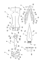
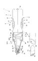
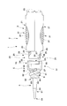
- the container for application which is a container according to the present embodiment is for applying, for example, an adhesive B as an application, and includes a container body 1 for storing the adhesive and a cap for sealing the tip of the container body 1.
- the container body 1 includes a nozzle 6 serving as an application portion of an adhesive B filled in a tube T serving as a sealed portion housed in the housing portion 2 by pressing a push button 3 attached to the housing portion 2 with a finger or the like.
- the adhesive B can be applied to the object from the tip surface 68 of the nozzle 6.
- the tip of the nozzle 6 is sealed by the cap 7, thereby preventing the adhesive B from touching the outside air.
- the specific description of the configuration of the cap 7 will be described later together with the middle cap 5 and the like.
- the tube T includes, for example, a tube main body T1 formed in a state where an aluminum plate formed into a thin plate shape holds the adhesive B hermetically, and an attachment screw portion T2 formed into a male screw shape at one end of the tube main body T1.
- An extraction surface T3 that allows the adhesive B to be extracted to the outside in a state where the aluminum material is torn inside the mounting screw portion T2 by making the aluminum material thin at the one end side of the mounting screw portion T2. have.
- the configuration of the tube T is, for example, an existing one designed to hold the existing adhesive B, liquid or gel chemicals, and the like. That is, the tube T alone can be used as a container.
- the abdomen T4 formed in a planar shape so as to make the front and back surfaces of the tube body T1 face each other is pressed with a finger or the like, so that the applied material, that is, the adhesive B from the portion where the aluminum material of the extraction surface T3 is broken. Can be extracted outside the tube T.
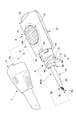
- the container main body 1 includes an inner cap 4 and a nozzle 6 mounted in the housing portion 2 in addition to the housing portion 2, the push button 3 and the nozzle 6. It has a middle cap 5 that is externally fitted to the accommodating portion 2 in a fixed state, and is assembled by appropriately assembling them.
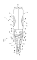
- the cap 7 includes a protrusion 74 that is inserted along the axial direction in which the nozzle 6 extends to the tip of the nozzle 6 in a state where the container body 1 is closed, and the protrusion An inclined rising surface 75 is provided, in which a rising portion where 74 rises is inclined with respect to the axis of the nozzle 6 extending.
- the configuration of the cap 7 will be described in detail later.
- the housing portion 2 is integrally molded of resin, for example, and has a so-called halved structure that is symmetrically molded via a resin hinge provided on the base end side opposite to the tip end where the nozzle 6 is positioned. Is. That is, the accommodating part 2 is hold
- the housing portion 2 is formed by opening a position corresponding to the center in both the longitudinal direction and the width direction so that the push button 3 can be exposed, and a groove for holding the push button 3 on the inner surface side and in the vicinity of the proximal end.
- the middle cap mounting portion 24 includes an engagement guide portion 25 to be described later, a separation guide portion 201 for separating the middle cap 5 at the time of sorting and discarding, and a separation guide portion 202 for guiding the separation guide portion to the separation guide portion. It is what has.
- the disengagement guide portion 201 is a groove extending in the longitudinal direction of the middle cap attachment portion 24 provided in the vicinity of the engagement guide portion 25.
- the disengagement guiding portion 202 is a rounded surface obtained by processing the surface from the engagement guide portion 25 to the disengagement guide portion 201 into a curved surface.
- the press button 3 has a symmetrical shape integrally formed of, for example, an elastic resin.
- the button main body 31 that is directly pressed by the user and the tube main body T1 that is pressed by the button main body 31 in detail.
- the pressing plate 32 that can press the flat abdomen T4 from one side and the other side with uniform strength, and the paired button body 31 and pressing plate 32 can be operated by the elasticity of the resin.
- a base end portion 33 that is exposed on the base end side of the housing portion 2. More specifically, the button main body 31 is curved at the proximal end side of the operation portion 34 and the operation portion 34 formed in an uneven shape in which a plurality of ribs are arranged at equal intervals so that a finger or the like can be easily picked without slipping.
- the pressing plate 32 protrudes in the opposite direction from the vicinity of the distal end portion, and the transmission rib 35 that can come into contact with the button main body 31 at the protruding end portion and the other end of the tube T at the proximal end portion are sandwiched and are preferential because they are thin.
- a sandwiching hinge 37 that can be curved.
- the push button 3 forms a pair of button main bodies 31 attached to the accommodating portion 2 that accommodates the tube T, and presses the button main body 31. It has a pressing plate 32 that forms a pair that is pressed and is in close contact with the abdomen T4 of the tube T.
- the pressing plate 32 presses the abdomen T4 of the tube T in a planar shape from the other end side, which is the opposite side of the extraction surface T3, to the one end side, which is the extraction surface T3 side.
- the tube T is sequentially pressed in a planar shape from the other end side toward one end side where the extraction surface T3 is provided.
- the adhesive B which is the contents in the tube T is stably extracted without waste.
- the contact position between the transmission rib 35 provided on the pressing plate 32 and the button main body 31 during the pressing operation slightly changes from the other end side to the one end side. Thereby, even if it is a tube with few remaining amount of adhesives B as shown in FIG.
- the inner cap 4 is for fixing the tube T inside the housing portion 2, and is inserted into the female screw portion 41 screwed to the mounting screw portion T 2 of the tube T and the inner cap mounting portion 23 of the housing portion 2. And a nozzle contact portion 43 that contacts the nozzle 6 and positions the nozzle 6 in the longitudinal direction.
- irregularities are formed on the outer peripheral surface of the mounting flange 42 so that the inner cap 4 can be smoothly screwed to the tube T. Further, the unevenness of the outer peripheral surface is engaged with a projection (not shown) provided on the inner surface of the inner cap mounting portion 23 when accommodated in the inner cap mounting portion 23, and prohibits relative rotation during mounting.
- the middle cap 5 is provided with a liquid dripping prevention part 50 at the tip, and can effectively avoid the problem that the adhesive B spilled from the nozzle 6 falls.
- the inner cap 5 forms an uneven knurl 5a (FIG. 11) on a part of the surface, and an outer fitting portion 51 that can cover the inner cap mounting portion 23 of the housing portion 2 from the outside, and a surface described later.
- the screw portion 8 screwed into the cap 7, the nozzle mounting portion 53 having the positioning groove 57 for fixing the nozzle 6 in the axial direction, And an opening (not shown) in which a part of the fitting portion 51 is opened.
- the outer fitting portion 51 has a rotation engagement claw 55 that can be engaged with the middle cap mounting portion 24 inward.
- the rotation engaging claw 55 is extended in the circumferential direction by appropriately cutting out the resin material, and protrudes inward at the tip of the extending portion 58, with respect to the middle cap mounting portion 24.
- an engagement end 59 for direct engagement.
- the nozzle 6 is integrally formed of a transparent or translucent resin so that the presence or absence of the internal adhesive B can be easily understood.
- the nozzle 6 includes a nozzle main body 61 that is exposed from the housing portion 2, a mounted portion 62 that is attached to the middle cap 5, and an extraction pipe 63 that extracts the adhesive B on the proximal side of the mounted portion 62. And have.
- the nozzle body 61 has an inclined tip portion 64 that forms a tip surface 68 by notching the tip end side in an inclined direction, and a tapered portion 69 formed so that the outer diameter gradually decreases until reaching the inclined tip portion 64. is doing.
- the mounted portion 62 includes a flange 65 positioned in the longitudinal direction of the middle cap 5, two large and small positioning ribs 66 a and 66 b that prohibit rotation around the axis and determine a relative angle with respect to the middle cap 5.
- the inclined tip portion 64 of the nozzle 6 forms a tip surface 68 by cutting the nozzle body 61 in an oblique direction.
- Such a front end surface 68 presents an obliquely flat cut surface in the nozzle body 61.
- the nozzle 6 makes the front-end
- variety of the adhesive agent B can be changed arbitrarily.
- the nozzle 6 has a directional shape.
- tip part 64 is set to 0.3 mm or less, and the amount of the adhesive agent B apply
- the container body 1 engages the accommodating portion 2 and the nozzle 6 with the nozzle 6 and the inner cap 5 being unable to apply the adhesive B.
- the first engaging position (P) and the nozzle 6 in which the accommodating portion 2 and the nozzle 6 have a predetermined direction from the first engaging position (P) apply the adhesive B.
- the housing portion 2 and the nozzle 6 can be engaged with each other at a second engagement position (Q) to be engaged so as not to be relatively movable in the obtained state, and the second engagement position (P) can be engaged with the second from the first engagement position (P).
- An engagement guide portion 25 that can guide the operation to the engagement position (Q), a disengagement guide portion 201 that can disengage the nozzle 6 and the middle cap 5 from the storage portion 2, and the second engagement position (Q). And a detachment guide part 202 for guiding the operation from the detachment guide part 201 to the detachment guide part 201. .
- the engagement guide portion 25 is provided in the middle cap attachment portion 24 of the housing portion 2, and the engagement guide portion 25 has a nozzle attachment portion 53 that can attach the nozzle 6 in a non-rotatable manner.
- the nozzle 6 is indirectly positioned to the first engagement position (P) and the second engagement position (Q) by engaging and guiding the rotary engagement claw 55 provided on the nozzle.
- the engagement guide portion 25 includes an introduction guide groove 26 for inserting the engagement end 59 and a first position for indirectly positioning the nozzle 6 at the first engagement position (P).
- the nozzle 6 is guided from the first engagement position (P) to the second engagement position (Q), so that the orientation of the nozzle 6 is suitable for use.
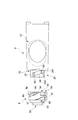
- a series of operations for setting the container body 1 to be usable while positioning the tube 6 and an operation for removing the nozzle 6 from the container 2 together with the middle cap 5 for separating and discarding the tube T will be described.
- FIG. 10 shows a mode in which the middle cap 5 to which the nozzle 6 is fixed is introduced toward the housing portion 2.
- the middle cap 5 is mounted in the cap 7 in such an operation. More specifically, the engagement end 59 of the rotation engagement claw 55 in the middle cap 5 is aligned with a position where it can be inserted into the introduction guide groove 26.
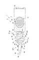
- the engagement end 59 is further moved to the base end side along the introduction guide groove 26 from this state, the engagement end 59 is fitted into the first engagement hole 27 and the first engagement position (P) is set.
- the base end of the nozzle 6, that is, the through end 67 of the extraction pipe 63 is separated from the extraction surface T3 of the tube T, so that the adhesive B can be injected into the nozzle 6. There is no state.
- the middle cap 5 is screw-fed so as to rotate the engagement end 59 along the rotation guide groove 28, the penetration end 67 passes through the extraction surface T3 and is inserted into the tube T while rotating.
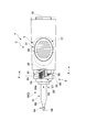
- the screw feeding operation is performed so as to rotate 90 ° from the first engagement position (P)
- the engagement end 59 is inserted into the second engagement hole 29 as shown in FIG.
- the engagement end 59 is fitted deeply into the second engagement hole 29, so that the engagement cannot be released unless the external force greatly exceeds the normal operation force.
- a series of operations up to here are performed through the cap 7. Therefore, in a state where the engagement end 59 is fitted in the second engagement hole 29, the cap positioning portion 70 abuts against the cap stopper 20 of the housing portion, and further rotation is prohibited.
- the positioning rib 66 of the nozzle 6 is fitted in the positioning groove 57 and the rotation operation is prohibited, and the flange 65 contacts the nozzle contact portion 43 and the operation in the extending direction of the nozzle 6 is also prohibited.
- the nozzle 6 is indirectly fixed to the accommodating portion 2 at the second engagement position (Q).
- the tip surface 68 of the nozzle 6 is in the same direction as the direction in which the button main body 31 of the push button 3 attached to the accommodating portion 2 is exposed. That is, the direction in which the operation unit 34 is exposed matches the direction in which the tip surface 68 of the nozzle 6 faces. Therefore, the direction in which the abdomen T4 and the operation unit 34 of the tube body T1 are exposed matches the direction in which the tip surface 68 of the nozzle 6 faces. That is, the pressing operation of the tube T and the visual recognition of the discharge of the adhesive B from the distal end surface 68 are facilitated. Thereby, the user can easily recognize the direction of the distal end surface 68 from the direction in which the button body 31 is pressed.
- a detachment structure in which the middle cap 5 can be detached from the accommodating portion 2 is adopted. That is, the middle cap 5 can be removed from the housing portion 2 by further rotating the middle cap 5 from the second engagement position (Q). Such an operation is performed without using the cap 7, such as picking the knurl 5 a provided on the middle cap 5 with a finger.
- a detachment structure is not limited to the detachment of the middle cap 5 from the housing portion 2, and can be applied to other applications.
- the present embodiment it is a to-be-removed element formed so that the middle cap 5 that is the disengaging element can be further disengaged from the second engaging position (Q) that is the engaging position by operating the middle cap 5.
- a separation guide portion 201 formed in the housing portion 2 and a separation guide portion 202 for guiding the engagement guide portion 201 to the separation guide portion 201 are provided. More specifically, when the knurling 5a provided on the surface of the middle cap 5 is picked and rotated further from the second engagement position (Q) shown in FIGS. 11 and 12, the state shown in FIG. Become. In this state, the engagement end 59 comes out of the second engagement hole 29 and is guided to the separation guide portion 202 so as to substantially contact the groove-shaped separation guide portion 201 extending to the upper end of the middle cap mounting portion 24. Take the position that can be removed.
- the middle cap 5 when the middle cap 5 is pulled from a state where the engaging end 59 is in contact with the separation guide portion 201 having a groove shape, the middle cap 5 can be detached from the housing portion 2 with a small force as shown in FIG. And the used tube T is taken out from the accommodating part 2 which removed the middle cap 5.
- the above-described detachment structure with the middle cap 5 as the detachable element and the accommodating portion 2 as the detachable element can be adopted as the structure of other various assembled products.
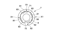
- the screw portion 8 includes a first screw groove 81 that is a single screw groove provided on the surface of the middle cap 5, and a second screw groove 82 that is deeper than the first screw groove 81 and has a larger width dimension.
- a step portion 83 provided at a portion other than the start end portion of the second screw groove including the start end portion of the first screw groove 81, and a step provided near the end of the second screw groove 82.
- an overpass portion 84 which is The second screw groove 82 is a single groove formed at a position where the angular phase is 180 ° different from that of the first screw groove.
- the ride-over portion 84 is When the second convex portion (not shown) of the cap 7 is exceeded, a click feeling is given to the user to let the user know that the second convex portion is approaching the end of the operation.
- the step portion 83 is a portion formed so that the outer diameter of the first end portion of the first screw groove 81 is increased by the difference in depth between the first screw groove 81 and the second screw groove 82. When the second convex portion comes into contact with the step portion 83, screwing of the cap 7 to the screw portion 8 is prohibited.
- the cap 7 is screwed so as to cover the front end side of the container body 1 so as to cover the nozzle 6.
- the cap 7 is formed, for example, by integral molding of a resin, and includes a first convex portion 71 and a second convex portion (not shown) formed by protruding the resin on the inner surface side, and an edge portion at the base end side edge portion.
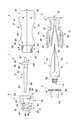
- a positioning portion 70 formed in a step shape, four sliding contact ribs 73 extending in the longitudinal direction in the vicinity of the distal end inside the cap 7 and capable of slidingly contacting the outer surface of the nozzle 6, and the proximal end from the inner surface of the distal end portion of the cap 7. It has a protruding portion 74 that protrudes in a cylindrical shape toward the side and can be inserted into the nozzle 6, and an inclined rising surface 75 that is a bottom surface on which the protruding portion 74 rises.
- the 1st convex part 71 is the 1986
- a second convex part (not shown) is formed at a position facing the first convex part 71, and corresponds to the depth dimension and the width dimension in which the second screw groove 82 is formed, that is, the first convex part.
- the positioning unit 70 can effectively hold the end position (Q1) by contacting the container body 1 side at the end position (Q1).
- the positioning portion 70 abuts against the cap 7 stopper provided in the housing portion, not the middle cap 7 in the container body 1. As a result, even if the user screws the cap 7 with a strong force, the acting force does not affect the middle cap 5.
- the sliding contact ribs 73 are provided at four equal intervals in the circumferential direction inside the cap 7, and the end positions (Q 1) are formed by inclining the tips according to the angle of the taper portion of the nozzle 6. It is slidably contacted with the taper part at the time of screwing up to, and plays the role of scraping off the adhesive B adhering to the taper part.
- the protrusion 74 is inserted so as to plug the inclined tip portion without a gap at the end position (Q1), so that the adhesive B in the nozzle 6 comes into contact with the outside air and is fixed at the end position (Q1). This is to avoid this.
- the projecting portion 74 has an inclined end 74a formed so as to face the forward / backward direction of the screwing, that is, the direction of the axis from the tip portion inside the cap 7 in an inclined direction. Due to the inclined end 74 a, the projecting portion 74 is configured not to interfere with the shape of the inclined tip end portion 64 of the nozzle 6.
- screwing always starts from a start position (P1) that is at a single relative position, regardless of the direction in which the user rotates the cap 7. Similarly, screwing ends at a single end position (Q1).
- the second convex portion rotates while being blocked by the step portion 83.
- the step portion 83 is also formed at the starting end of the first screw groove 81, the second convex portion is not erroneously inserted into the first screw groove 81.
- the 1st convex part 71 and the 2nd convex part enter in the 1st thread groove and the 2nd thread groove 82, it is the starting position (P1) shown in FIG. 15, and screwing is started from here.
- the protrusion 74 is in a state in which the inclined end 74a faces the front of the drawing, and has not yet contacted the inclined tip 64.
- the first convex portion 71 and the second convex portion proceed through the first screw groove 81 and the second screw groove 82, respectively, as shown in FIG.
- the tip surface 68 of the nozzle 6 facing diagonally upward and the inclined end 74a of the projecting portion 74 facing diagonally downward face each other, and The contact is slightly made, and the insertion of the inclined end 74a into the inclined tip portion 64 starts from here.
- the inclined tip portion 64 is set to have a thin material thickness of 0.3 mm, there may be some distortion and bending from the state shown in the figure, but the protrusion 74 is inserted to Bending will be corrected.
- the 1st convex part 71 and the 2nd convex part advance the inside of the 1st thread groove 81 and the 2nd thread groove 82, and rotate 180 degrees from the start position (P1), the cap 7 is the end position (Q1 shown in FIG. 17).
- the end position (Q1) of the cap 7 the first convex portion 71 and the second convex portion do not contact the terminal ends of the first screw groove 81 and the second screw groove 82.
- the tip surface 68 is in a state of being in close proximity to the inclined rising surface 75 and is in a state facing the back in the orientation illustration of the inclined end 74a, that is, the direction of the tip surface 68 has a 90 ° phase. It is in a different state.
- tip part 64 is made small, and the influence on the protrusion part 74 by the adhesive agent B at the time of opening the cap 7 is suppressed to the minimum.
- the rising area of the protrusion 74 is inclined from the axial direction, specifically, from the virtual plane orthogonal to the axial direction. Therefore, the area is larger than the cross-sectional area from the angle orthogonal to the axial direction of the protrusion 74 itself. As a result, the protruding portion 74 can be raised with a larger area, and the strength of the rising portion is particularly high. Thereby, the cap 7 which can hardly be damaged by the adhesive B and can stably cover the container main body 1, that is, the inclined tip portion 64 of the nozzle 6, is realized.
- the inclined tip portion 64 of the nozzle 6 is applied. Secure positioning of the protrusion 74 is ensured.
- the tip of the protrusion 74 is formed as an inclined end, so that it can be smoothly inserted into the inclined tip 64 while avoiding interference with the nozzle 6 during screwing.
- the protrusion 74 is formed into a thin wall that is difficult to secure the shape as in the same embodiment by realizing easy and reliable insertion of the protrusion 74 into the inclined tip 64. Even with respect to the inclined tip portion 64 set to 0.3 mm or less, the shape of the inclined tip portion 64 is effectively secured by inserting the protruding portion 74 easily and reliably.
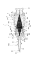
- the container for application is, for example, for applying an adhesive B as an application, and includes a container body 1 that contains the adhesive and a cap 7 that seals the tip of the container body 1.
- the container body 1 includes a nozzle 6 serving as an application portion of an adhesive B filled in a tube T serving as a sealed portion housed in the housing portion 2 by pressing a push button 3 attached to the housing portion 2 with a finger or the like.
- the adhesive B can be applied to the object from the tip surface 68 of the nozzle 6.
- the tip of the nozzle 6 is sealed by the cap 7 as shown in FIG. 20, thereby preventing the adhesive B from touching the outside air.
- the specific description of the configuration of the cap 7 will be described later together with the middle cap 5 and the like.
- the tube T includes, for example, a tube main body T1 formed in a state where an aluminum plate formed into a thin plate shape holds the adhesive B hermetically, and an attachment screw portion T2 formed into a male screw shape at one end of the tube main body T1.
- An extraction surface T3 that allows the adhesive B to be extracted to the outside in a state where the aluminum material is torn inside the mounting screw portion T2 by making the aluminum material thin at the one end side of the mounting screw portion T2. have.
- the configuration of the tube T is, for example, an existing one designed to hold the existing adhesive B, liquid or gel chemicals, and the like. That is, the tube T alone can be used as a container.
- the abdomen T4 formed in a planar shape so as to make the front and back surfaces of the tube body T1 face each other is pressed with a finger or the like, so that the applied material, that is, the adhesive B from the portion where the aluminum material of the extraction surface T3 is broken. Can be extracted outside the tube T.
- the container body 1 includes, as its constituent parts, an inner cap 4 and a nozzle 6 mounted in the housing portion 2 in addition to the housing portion 2, the push button 3 and the nozzle 6. It has a middle cap 5 that is externally fitted to the accommodating portion 2 in a fixed state, and is assembled by appropriately assembling them.
- the container main body 1 is configured to apply the adhesive B accommodated in the accommodating part 2 that accommodates the adhesive B and has a directionality to the object.
- a container body 1 having a nozzle 6 formed with an inclined tip 64 having a directivity and attached to the housing portion 2, wherein the nozzle 6 cannot apply the adhesive B.
- the first engaging position (P) for engaging the accommodating portion 2 and the nozzle 6, and the accommodating portion 2 and the nozzle 6 have a predetermined direction from each other from the first engaging position (P). None and the second engaging position (Q) in which the nozzle 6 can be applied with the adhesive B so that the nozzle 6 can be applied with the adhesive B, the housing portion 2 and the nozzle 6 can be engaged with each other. Movement from one engagement position (P) to the second engagement position (Q) And characterized by being provided with an engaging guide portion 25 that can guide the.
- the screwing structure X applied to the container main body 1 and the cap 7 includes the first screw groove 81 provided in the container main body 1 that is a member to be screwed, and the first screw groove.
- the container body 1 and the cap 7 are provided on a cap 7 that can be screwed onto a container body that can be inserted, and the container body 1 and the cap 7 are rotated relative to each other from a start position (P1) that forms a predetermined relative angle.
- a first threaded portion X1 having a first convex portion 71 provided for screwing at an end position (Q1) forming an angle, and a recess deeper than the first screw groove 81 are provided in the container body 1.
- the second screw groove 82 and the second convex portion 72 provided on the cap 7 so as to be inserted and screwed only into the predetermined second screw groove 82 and not to be inserted into the first screw groove 81 are provided. It has the 2nd screwing part X2 which has. The screw structure X will be described in detail later.
- the housing portion 2 is integrally molded of resin, for example, and has a so-called halved structure that is symmetrically molded via a resin hinge provided on the base end side opposite to the tip end where the nozzle 6 is positioned. Is. That is, the accommodating part 2 is hold
- the housing portion 2 is formed by opening a position corresponding to the center in both the longitudinal direction and the width direction so that the push button 3 can be exposed, and a groove for holding the push button 3 on the inner surface side and in the vicinity of the proximal end.
- a button mounting portion 22 an inner cap mounting portion 23 that is a groove for holding the inner cap 4 on the inner surface side and in the vicinity of the tip, and a middle cap mounting portion 24 to which the middle cap 5 can be fitted.
- this outer cap attaching part 24 has the engagement guide part 25 which concerns on this embodiment, The detailed structure of the said engagement guide part 25 is explained in full detail behind.
- the press button 3 has a symmetrical shape integrally formed of, for example, an elastic resin.
- the button main body 31 that is directly pressed by the user and the tube main body T1 that is pressed by the button main body 31 in detail.
- the pressing plate 32 that can press the flat abdomen T4 from one side and the other side with uniform strength, and the paired button body 31 and pressing plate 32 can be operated by the elasticity of the resin.
- a base end portion 33 that is exposed on the base end side of the housing portion 2.
- the button main body 31 is close to the operation portion 34 formed in a concavo-convex shape in which a plurality of ribs are arranged at equal intervals so that a finger or the like can be easily picked without slipping, and the proximal end side of the operation portion 34. It has a transmission rib 35 that protrudes in the direction and can come into contact with the pressing plate 32 at the protruding end.
- the inner cap 4 is for fixing the tube T inside the housing portion 2, and is inserted into the female screw portion 41 screwed to the mounting screw portion T 2 of the tube T and the inner cap mounting portion 23 of the housing portion 2. And a nozzle contact portion 43 that contacts the nozzle 6 and positions the nozzle 6 in the longitudinal direction.
- irregularities are formed on the outer peripheral surface of the mounting flange 42 so that the inner cap 4 can be smoothly screwed to the tube T.
- the middle cap 5 is provided with a liquid dripping prevention part 50 at the tip, and can effectively avoid the problem that the adhesive B spilled from the nozzle 6 falls.
- this inner cap 5 forms the external fitting part 51 which can cover the inner cap attaching part 23 of the accommodating part 2 from the outer side, and the 1st thread groove 81 and the 2nd thread groove 82 which are the thread surfaces 56 which are mentioned later on the surface.
- the screw portion 8 screwed to the cap 7, the nozzle mounting portion 53 having the positioning groove 57 for fixing the nozzle 6 in the axial direction, and the opening portion 54 in which a part of the outer fitting portion 51 is opened. have.
- the outer fitting portion 51 has a rotation engagement claw 55 that can be engaged with the middle cap mounting portion 24 inward.
- the rotation engaging claw 55 is extended in the circumferential direction by appropriately cutting out the resin material, and protrudes inward at the tip of the extending portion 58, with respect to the middle cap mounting portion 24. And an engagement end 59 for direct engagement.
- a specific configuration of the screw portion 8 will be described in detail later.
- the nozzle 6 is integrally formed of a transparent or translucent resin so that the presence or absence of the internal adhesive B can be easily understood.
- the nozzle 6 includes a nozzle main body 61 that is exposed from the housing portion 2, a mounted portion 62 that is attached to the middle cap 5, and an extraction pipe 63 that extracts the adhesive B on the proximal side of the mounted portion 62. And have.
- the nozzle body 61 has an inclined tip portion 64 that forms a tip surface 68 by notching the tip end side in the inclined direction, and a tapered portion 69 that is formed so that the outer diameter gradually decreases until reaching the inclined tip portion. ing.
- the mounted portion 62 has a flange 65 positioned in the longitudinal direction with respect to the middle cap 5 and a protruding positioning rib 66 for prohibiting rotation around the axis.
- the inclined tip portion 64 of the nozzle 6 forms a tip surface 68 by cutting the nozzle body 61 in an oblique direction.
- Such a front end surface 68 presents an obliquely flat cut surface in the nozzle body 61.
- the nozzle 6 makes the front-end
- the container main body 1 has the first engagement position (P) in which the nozzle 6 is engaged with the housing portion 2 and the nozzle 6 in a state where the adhesive B cannot be applied. And the accommodating portion 2 and the nozzle 6 from the first engagement position (P) are engaged with each other so that the nozzle 6 can apply the adhesive B in a state in which the nozzle 6 has a predetermined direction.
- the accommodating portion 2 and the nozzle 6 can be engaged with each other at the second engagement position (Q), and the operation from the first engagement position (P) to the second engagement position (Q) is performed. It is provided with the engagement guide part 25 which can guide.
- the engagement guide portion 25 is provided in the outer cap attachment portion 24 of the housing portion 2, and the engagement guide portion 25 has the nozzle cap portion 53 that can attach the nozzle 6 in a non-rotatable manner.
- the nozzle 6 is indirectly positioned to the first engagement position (P) and the second engagement position (Q) by engaging and guiding the rotary engagement claw 55 provided on the nozzle.
- the engagement guide portion 25 includes an introduction guide groove 26 for inserting the engagement end 59 and a first position for indirectly positioning the nozzle 6 at the first engagement position (P).
- the rotation guide groove 28 that is a groove continuous from the first engagement hole 27 in the screw feeding direction, and the engagement end 59 is positioned so as not to move by being guided by the rotation guide groove 28.
- a second engagement hole 29 for indirectly fixing the nozzle 6 to the second engagement position (Q).
- the nozzle 6 is guided from the first engagement position (P) to the second engagement position (Q) so that the orientation of the nozzle 6 is suitable for use.
- a series of operations for setting the container main body 1 in a usable state while positioning to the position will be described.
- FIG. 23 shows a mode in which the middle cap 5 to which the nozzle 6 is fixed is introduced toward the housing portion 2. Specifically, the engagement end 59 of the rotation engagement claw 55 is adjusted to a position where it can be inserted into the introduction guide groove 26. When the engagement end 59 is further moved to the proximal end side along the introduction guide groove 26 from this state, the first engagement position (P) shown in FIGS. 25 and 27 is taken. In this first engagement position (P), the base end of the nozzle 6, that is, the through end 67 of the extraction pipe 63 is separated from the extraction surface T3 of the tube T, so that the adhesive B can be injected into the nozzle 6. There is no state.
- the middle cap 5 when the middle cap 5 is screw-fed so as to rotate the engagement end 59 along the rotation guide groove 28 from the state shown in FIG. 25, the penetration end 67 passes through the extraction surface T3 while rotating through the tube T. Is inserted.
- the screw feeding operation when the screw feeding operation is performed so as to rotate 90 ° from the first engagement position (P), the engagement end 59 is inserted into the second engagement hole 29 as shown in FIGS. Is done. In this state, the engagement end 59 is fitted deeply into the second engagement hole 29, so that the engagement cannot be released unless the external force greatly exceeds the normal operation force.
- the positioning rib 66 of the nozzle 6 is fitted in the positioning groove 57 and the rotation operation is prohibited, and the flange 65 contacts the nozzle contact portion 43 and the operation in the extending direction of the nozzle 6 is also prohibited.
- the nozzle 6 is indirectly fixed to the accommodating portion 2 at the second engagement position (Q).
- the front end surface 68 of the nozzle 6 has faced the same direction as the direction which the button main body 31 of the press button 3 attached to the accommodating part 2 exposes. . That is, the direction in which the operation unit 34 is exposed matches the direction in which the tip surface 68 of the nozzle 6 faces. Therefore, the direction in which the abdomen T4 and the operation unit 34 of the tube body T1 are exposed matches the direction in which the tip surface 68 of the nozzle 6 faces. That is, the pressing operation of the tube T and the visual recognition of the discharge of the adhesive B from the distal end surface 68 are facilitated. Accordingly, the user can easily recognize the direction of the distal end surface 68 from the direction in which the button body 31 is pressed, and can apply the adhesive B in a state in which the user can easily grasp it.
- the screwing structure X is realized by the screw portion 8 and the cap X provided in the middle cap 5.
- the screw portion 8 includes a first screw groove 81 that is a single screw groove provided on the surface of the middle cap 5, and a second screw groove 82 that is deeper than the first screw groove 81 and has a larger width dimension.
- a step portion 83 provided at a portion other than the start end portion of the second screw groove including the start end portion of the first screw groove 81, and a step provided near the end of the second screw groove 82.
- an overpass portion 84 which is The second screw groove 82 is a single groove formed at a position where the angular phase is 180 ° different from that of the first screw groove.
- the ride-over portion 84 is When the second convex portion 72 is exceeded, a click feeling is given to the user, so that the second convex portion 72 is approaching the end of the operation.
- the step portion 83 is a portion formed so that the outer diameter of the first end portion of the first screw groove 81 is increased by the difference in depth between the first screw groove 81 and the second screw groove 82. When the second convex portion 72 comes into contact with the step portion 83, screwing of the cap 7 to the screw portion 8 is prohibited.
- the cap 7 is screwed so as to cover the front end side of the container body 1 so as to cover the nozzle 6.
- the cap 7 is formed by integral molding of resin, for example, and includes a first convex portion 71 and a second convex portion 72 formed by protruding the resin on the inner surface side, and a stepped shape at the edge at the base end side edge.
- the formed positioning portion 70 for example, four sliding contact ribs 73 that extend in the longitudinal direction in the vicinity of the distal end inside the cap 7 and can come into sliding contact with the outer surface of the nozzle 6, and toward the proximal end side from the inner surface of the distal end portion of the cap 7.
- the 1st convex part 71 is the protrusion protruded in the substantially rectangular shape corresponding to the depth dimension and width dimension in which said 1st screw groove 81 is formed.
- the second convex part 72 is formed at a position facing the first convex part 71, and corresponds to the depth dimension and the width dimension in which the second screw groove 82 is formed, that is, from the first convex part 71. Furthermore, by projecting into a rectangular shape having a large projecting dimension and projecting area, the second thread groove 82 can be inserted without rattling.
- the positioning unit 70 can effectively hold the end position (Q1) by contacting the container body 1 side at the end position (Q1).
- the positioning portion 70 abuts against the cap stopper 20 provided in the housing portion, not the middle cap 7 in the container body 1.
- the sliding contact ribs 73 are provided at four equal intervals in the circumferential direction inside the cap 7, and the end positions (Q 1) are formed by inclining the tips according to the angle of the taper portion of the nozzle 6. It is slidably contacted with the taper part at the time of screwing up to, and plays the role of scraping off the adhesive B adhering to the taper part.
- the insertion rib 74 is inserted so as to plug the inclined tip portion without a gap at the end position (Q1), so that the adhesive B in the nozzle 6 comes into contact with the outside air and is fixed at the end position (Q1). This is to avoid this.
- the first screw groove 81 and the first convex portion 71 described above constitute the first threaded portion X1 of the present embodiment
- the second screw groove 82 and the second convex portion 72 are the present embodiment.
- the 2nd screwing part X2 is comprised.
- the second convex portion 72 is blocked by the step portion 83 as shown in FIG. Rotate in the state.
- the step portion 83 is also formed at the starting end of the first screw groove 81, the second convex portion 72 is not erroneously inserted into the first screw groove 81.
- the 2nd convex part 72 has started the 2nd thread groove 82, it is a start position (P1) shown in FIG. 36, and screwing is started from here.
- the first convex portion 71 is also inserted into the first screw groove 81.
- the first convex portion 71 and the second convex portion 72 advance in the first screw groove 81 and the second screw groove 82, respectively, as shown in the upper and middle stages of FIGS. .
- the 1st convex part 71 and the 2nd convex part 72 advance in the 1st thread groove 81 and the 2nd thread groove 82, and rotate 180 degrees from the start position (P1), the cap 7 is positioned in the end position (Q1). Is done.
- the first convex portion 71 and the second convex portion 72 are not in contact with the terminal ends of the first screw groove 81 and the second screw groove 82 at the end position (Q1).
- the positioning part 70 provided at a location different from the second convex part 72 abuts not the screw part but the cap stopper 20 provided on the container 2 side of the container body 1.
- the container body 1 applies the adhesive B accommodated in the accommodating part 2 that accommodates the adhesive B and has the directionality, and the adhesive B accommodated in the accommodating part 2 to the object.
- the container 2 and the nozzle 6 can be engaged with each other at a second engagement position (Q) in which the nozzle 6 can be applied with the adhesive B so that the nozzle 6 can be applied without relative movement. From the first engagement position (P) to the second engagement position (Q) And characterized by being provided with an engaging guide portion 25 that can guide the operation.
- the container body 1 according to the present embodiment can be stored, shipped, transported, etc., as long as the nozzle 6 is engaged with a desired position, that is, the first engagement position (P). It is possible to maintain a state in which the adhesive B, which is a coating material, cannot be leaked or applied by mistake.
- the guide can be accurately guided from the first engagement position (P) to the second engagement position (Q) by the engagement guide portion 25, the user can easily use the container body 1.
- the adhesive agent B can be apply
- the relative movement between the accommodating portion 2 and the nozzle 6 is prohibited at the second engagement position (Q), the user can suitably perform the application work.
- the engagement guide portion 25 is rotated relative to the nozzle 6 and the storage portion 2. It is assumed that the second engagement position (Q) is guided by performing a screw feeding operation.
- the inclined tip portion 64 of the nozzle 6 is positioned according to the orientation of the accommodating portion 2, so that the user can easily adjust the orientation of the nozzle 6 and suitably apply the adhesive B. It is said.
- the accommodating part 2 accommodates the adhesive B by accommodating the tube T in which the adhesive B is sealed, and the base end of the nozzle 6 at the second engagement position (Q). It is assumed that the extraction tube 63 located in can be inserted into the tube T.
- a button that can supply the adhesive B to the nozzle 6 when the storage portion 2 is pressed.
- the direction of the nozzle 6 and the supply amount of the adhesive B can be freely adjusted by aligning the direction of the inclined tip 64 in the direction in which the button is exposed from the housing 2. It has become.
- the screwing structure X applied to the container main body 1 and the cap 7 includes the first screw groove 81 provided in the container main body 1 that is a member to be screwed, and the first screw groove.
- a cap 7 that is a screwed body that can be screwed into the container main body 1 that can be inserted is relatively rotated from a start position (P) that forms a predetermined relative angle.
- a first threaded portion X1 having a first convex portion 71 provided to be screwed in an end state (Q) having a relative angle, and a recess deeper than the first screw groove 81, are formed in the container body 1.
- the second screw groove 82 provided and the second protrusion 72 provided in the cap 7 so as to be inserted and screwed only into the predetermined second screw groove 82 and not to be inserted into the first screw groove 81. It has the 2nd screwing part X2 which has.
- the 2nd convex part 72 becomes a structure which can be inserted only in the predetermined
- the length dimension of the second convex portion 72 protruding in the inner direction of the cap 7 is set.
- the first convex portion 71 is set to be larger than the length dimension from which the first convex portion 71 protrudes, and the width dimension of the second thread groove 82 and the dimension of the second convex portion 72 corresponding to the width dimension are set to the first thread groove 81. It is set larger than the width dimension.
- the step 83 is provided at the insertion end for inserting the first convex portion at the start position (P1) in the first thread groove 81, the second convex portion 72 interferes with the first thread groove 81.
- the cap 7 and the container body 1 are smoothly rotated relatively until the second screw groove 82 is reached without causing the user to feel uncomfortable when the second convex portion 72 passes through the first screw groove 81. There is no.
- first screwing portion X1 and the second screwing portion X2 are provided at positions that face each other in order to achieve both a simple configuration and accurate screwing. Further, the first screwing portion X1 and the second screwing portion X2 are opposed to each other, that is, the 180 ° angle phase is varied to effectively avoid a partial strength variation.
- a positioning portion 70 for positioning the container body 1 and the cap 7 at the end position (Q1) at a position different from the first screwing portion X1 and the second screwing portion X2 Even if an acting force in the direction of further screwing is applied from the end position (Q1), it is effectively avoided that unnecessary force is applied to the first screwing portion X1 and the second screwing portion X2.
- FIG. 41 shows the first threaded portion X1 and the second threaded portion X2 provided at the same angle phase as in the above embodiment, but the size of the inner surface of the cap 7 from which the first convex portion 71 projects is shown in FIG. The same ⁇ as that of the biconvex portion 72 is set. Even if it is such, there exists an effect
- first screwing portions X1 are provided, that is, two and three.
- the second convex portion 72 can enter the first thread groove 81 as in the above embodiment. Therefore, the second protrusion 72 can be inserted into the second screw groove 82 at the exact start position (P1) as in the above embodiment. That is, in the screwing structure X according to the present embodiment, the number and arrangement of the first screwing portions X1 can be variously changed.
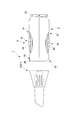
- the container main body 10 is flat in the direction of the front end surface 68 of the nozzle 6 and the direction of the button main body 31a exposed from the accommodating portion 2 at the second engagement position (Q) as in the above embodiment.
- the engagement guide portion 25a has the second engagement in the direction in which the nozzle 6 and the accommodating portion 2 are joined from the first engagement position (P). A mode of guiding to the matching position (Q) is applied.
- the configuration of the container body 10 will be mainly described in the configuration different from the above embodiment.
- the inner cap 4, the nozzle 6, the tube T, and the cap 7 have substantially the same configuration as that of the above embodiment, and thus detailed description thereof is omitted.
- the housing portion 2 has a substantially halved structure having a button hole 21, a button attachment portion 22, and an inner cap attachment portion 23 similar to the above embodiment, but the outer cap attachment portion 24a is an inner cap attachment portion.
- the push button 3 includes a pair of button main bodies 31a that are operatively connected to the base end portion 33.
- An operation portion 34a that can be directly operated by the button main body 31a and a tube main body directly on the back side of the operation portion 34a. It has a pressing surface 32a that can uniformly press the abdominal part T4 of T1, and the configuration of the pressing plate 32 in the above embodiment is omitted.
- the middle cap 5 has a configuration similar to that of the above embodiment with respect to the cover stopper 52 and the nozzle mounting portion 53, but the configuration of the opening 54 is omitted. And it has the insertion part 51a for mounting
- the insertion portion 51a has a total of four pressing engagement claws 55a protruding from the cover stopper 52 to the proximal end side.
- the pressing engagement claws 55a include an extension portion 58a extending to the proximal end side, It has an engagement end 59a that engages with the engagement guide portion 25a at the tip of the extension portion 58a.
- the engagement guide portion 25a is provided with the first engagement position (P) so as to facilitate the accurate positioning of the accommodating portion 2 and the nozzle 6 at the second engagement position (Q). ) To the second engagement position (Q) along the direction in which the nozzle 6 and the accommodating portion 2 are joined is applied.
- the engagement guide portion 25a is a first engagement hole for inserting the engagement end 59a and indirectly positioning the nozzle 6 at the first engagement position (P).
- a pressing guide groove 28a that is a groove that continues linearly from the first engagement hole 27a, and the engagement end 59a that is guided by the pressing guide groove 28a is positioned so as to be immovable.
- a second engagement hole 29a that is indirectly fixed to the second engagement position (Q).
- the nozzle 6 is guided from the first engagement position (P) to the second engagement position (Q), so that the orientation of the nozzle 6 is suitable for use.
- a series of operations for setting the container main body 10 to be usable while positioning to the position will be described.
- FIG. 48 shows a mode in which the middle cap 5 to which the nozzle 6 is fixed is introduced toward the housing portion 2. Specifically, the engagement end 59a of the press engagement claw 55a is engaged with the first engagement hole 27a which is the first engagement position (P). In this first engagement position (P), the base end of the nozzle 6, that is, the through end 67 of the extraction pipe 63 is separated from the extraction surface T3 of the tube T, so that the adhesive B can be injected into the nozzle 6. There is no state.
- the positioning rib 66 of the nozzle 6 is fitted in the positioning groove 57 and the rotation operation is prohibited, and the flange 65 contacts the nozzle contact portion 43 and the operation in the extending direction of the nozzle 6 is also prohibited.
- the nozzle 6 is indirectly fixed to the accommodating portion 2 at the second engagement position (Q).
- the front end surface 68 of the nozzle 6 is in the state which faced the same direction as the direction which the button main body 31a of the press button 3 attached to the accommodating part 2 exposes. . Thereby, the user can apply the adhesive B in a state in which the direction of the front end surface 68 can be easily grasped from the direction in which the button body 31a is pressed.
- the nozzle 6 is preferably positioned to the second engagement position (Q). Ten comfortable uses are guaranteed.
- the aspect in which the cap is mounted by screwing back and forth is disclosed, but of course, the aspect in which the cap is inserted along the axial direction may be used.
- the specific aspect of a nozzle, a tube, or a press button is not limited to the thing of the said embodiment, The thing of various aspects including an existing thing is applicable.
- the present invention can be used as a container having a cap for plugging a container containing an adhesive.
Landscapes
- Engineering & Computer Science (AREA)
- Mechanical Engineering (AREA)
- Closures For Containers (AREA)
Applications Claiming Priority (6)
| Application Number | Priority Date | Filing Date | Title |
|---|---|---|---|
| JP2012025388A JP2013159392A (ja) | 2012-02-08 | 2012-02-08 | 塗布用容器 |
| JP2012-025388 | 2012-02-08 | ||
| JP2012-096624 | 2012-04-20 | ||
| JP2012096625A JP2013224161A (ja) | 2012-04-20 | 2012-04-20 | 螺着構造 |
| JP2012096624A JP2013224160A (ja) | 2012-04-20 | 2012-04-20 | 容器 |
| JP2012-096625 | 2012-04-20 |
Publications (1)
| Publication Number | Publication Date |
|---|---|
| WO2013118582A1 true WO2013118582A1 (fr) | 2013-08-15 |
Family
ID=48947349
Family Applications (1)
| Application Number | Title | Priority Date | Filing Date |
|---|---|---|---|
| PCT/JP2013/051393 Ceased WO2013118582A1 (fr) | 2012-02-08 | 2013-01-24 | Récipient |
Country Status (2)
| Country | Link |
|---|---|
| TW (1) | TW201348085A (fr) |
| WO (1) | WO2013118582A1 (fr) |
Cited By (7)
| Publication number | Priority date | Publication date | Assignee | Title |
|---|---|---|---|---|
| WO2017140724A1 (fr) * | 2016-02-18 | 2017-08-24 | Henkel Ag & Co. Kgaa | Dispositif pour appliquer un adhésif ou un matériau d'étanchéité |
| JP2019025399A (ja) * | 2017-07-28 | 2019-02-21 | コクヨ株式会社 | 塗布製品 |
| EP3666674A1 (fr) * | 2018-12-14 | 2020-06-17 | The Gorilla Glue Company LLC | Outil pour distribuer un matériau visqueux à partir d'un tube déformable |
| USD918295S1 (en) | 2018-12-14 | 2021-05-04 | The Gorilla Glue Company Llc | Dispenser for adhesive |
| USD950645S1 (en) | 2019-11-27 | 2022-05-03 | The Gorilla Glue Company Llc | Dispenser |
| US11407563B2 (en) | 2019-11-27 | 2022-08-09 | The Gorilla Glue Company Llc | Devices and systems for dispensing material |
| KR102564677B1 (ko) | 2023-02-21 | 2023-08-08 | 주식회사 원진포리머 | 튜브용 압출장치 |
Families Citing this family (1)
| Publication number | Priority date | Publication date | Assignee | Title |
|---|---|---|---|---|
| US10939897B2 (en) | 2019-02-21 | 2021-03-09 | GeneJet Biotech Co., Ltd. | Hand-held adhesive deliver apparatus |
Citations (3)
| Publication number | Priority date | Publication date | Assignee | Title |
|---|---|---|---|---|
| US4090647A (en) * | 1976-07-21 | 1978-05-23 | Dunning Belford O | Applicator container |
| JPS6429158U (fr) * | 1987-08-14 | 1989-02-21 | ||
| JPH08506311A (ja) * | 1994-03-11 | 1996-07-09 | ロックタイト コーポレイション | 瞬間接着剤用の新規な容器 |
-
2013
- 2013-01-24 WO PCT/JP2013/051393 patent/WO2013118582A1/fr not_active Ceased
- 2013-02-04 TW TW102104207A patent/TW201348085A/zh unknown
Patent Citations (3)
| Publication number | Priority date | Publication date | Assignee | Title |
|---|---|---|---|---|
| US4090647A (en) * | 1976-07-21 | 1978-05-23 | Dunning Belford O | Applicator container |
| JPS6429158U (fr) * | 1987-08-14 | 1989-02-21 | ||
| JPH08506311A (ja) * | 1994-03-11 | 1996-07-09 | ロックタイト コーポレイション | 瞬間接着剤用の新規な容器 |
Cited By (12)
| Publication number | Priority date | Publication date | Assignee | Title |
|---|---|---|---|---|
| WO2017140724A1 (fr) * | 2016-02-18 | 2017-08-24 | Henkel Ag & Co. Kgaa | Dispositif pour appliquer un adhésif ou un matériau d'étanchéité |
| KR20180113504A (ko) * | 2016-02-18 | 2018-10-16 | 헨켈 아게 운트 코. 카게아아 | 접착제 및/또는 실런트를 도포하기 위한 디바이스 |
| JP2019508236A (ja) * | 2016-02-18 | 2019-03-28 | ヘンケル・アクチェンゲゼルシャフト・ウント・コムパニー・コマンディットゲゼルシャフト・アウフ・アクチェンHenkel AG & Co. KGaA | 接着剤および/またはシーリング剤を塗布するための装置 |
| US11383265B2 (en) | 2016-02-18 | 2022-07-12 | Henkel Ag & Co. Kgaa | Device for applying adhesive and/or sealant |
| KR102621212B1 (ko) | 2016-02-18 | 2024-01-04 | 헨켈 아게 운트 코. 카게아아 | 접착제 및/또는 실런트를 도포하기 위한 디바이스 |
| JP2019025399A (ja) * | 2017-07-28 | 2019-02-21 | コクヨ株式会社 | 塗布製品 |
| EP3666674A1 (fr) * | 2018-12-14 | 2020-06-17 | The Gorilla Glue Company LLC | Outil pour distribuer un matériau visqueux à partir d'un tube déformable |
| USD918295S1 (en) | 2018-12-14 | 2021-05-04 | The Gorilla Glue Company Llc | Dispenser for adhesive |
| US11261018B2 (en) | 2018-12-14 | 2022-03-01 | The Gorilla Glue Company Llc | Tool for dispensing viscous material from a deformable tube |
| USD950645S1 (en) | 2019-11-27 | 2022-05-03 | The Gorilla Glue Company Llc | Dispenser |
| US11407563B2 (en) | 2019-11-27 | 2022-08-09 | The Gorilla Glue Company Llc | Devices and systems for dispensing material |
| KR102564677B1 (ko) | 2023-02-21 | 2023-08-08 | 주식회사 원진포리머 | 튜브용 압출장치 |
Also Published As
| Publication number | Publication date |
|---|---|
| TW201348085A (zh) | 2013-12-01 |
Similar Documents
| Publication | Publication Date | Title |
|---|---|---|
| WO2013118582A1 (fr) | Récipient | |
| JP6067142B2 (ja) | 化粧品容器キャップ | |
| JP6102936B2 (ja) | 塗布製品 | |
| CN103998074B (zh) | 针尖存储和移除装置 | |
| JP5695485B2 (ja) | 注射器 | |
| WO2008067220A3 (fr) | Distributeur | |
| JP2012500753A (ja) | 放出装置用のコネクタ | |
| US12194456B2 (en) | Blood collection tube holder and blood collection kit | |
| US8529519B2 (en) | Tight-sealing cap for liquid drug-expelling part | |
| JP6540001B2 (ja) | 塗布用容器 | |
| JP2013159392A (ja) | 塗布用容器 | |
| JP2008254769A (ja) | チューブ容器 | |
| JP2016159937A (ja) | 積層剥離容器 | |
| JP2013224160A (ja) | 容器 | |
| US9650188B1 (en) | Delayed pierce, sealed container | |
| US20060185107A1 (en) | Cosmetic application device | |
| JP2013224161A (ja) | 螺着構造 | |
| JP5610775B2 (ja) | 液体塗布具 | |
| JP5587584B2 (ja) | 流動物押出用容器 | |
| US20190090613A1 (en) | Cosmetic applicator having side control button | |
| JP6540002B2 (ja) | 塗布用容器 | |
| US20110272439A1 (en) | Discharge structure for a liquid container | |
| KR101477332B1 (ko) | 복수의 재료들을 혼합하고 배출하는 장치 | |
| KR101863707B1 (ko) | 밀폐부재가 구비된 화장품 용기 | |
| JP2016086965A (ja) | カテーテルコネクタ |
Legal Events
| Date | Code | Title | Description |
|---|---|---|---|
| 121 | Ep: the epo has been informed by wipo that ep was designated in this application |
Ref document number: 13746999 Country of ref document: EP Kind code of ref document: A1 |
|
| NENP | Non-entry into the national phase |
Ref country code: DE |
|
| 122 | Ep: pct application non-entry in european phase |
Ref document number: 13746999 Country of ref document: EP Kind code of ref document: A1 |