WO2013118687A1 - Système informatique et procédé de visualisation de réseau virtuel - Google Patents
Système informatique et procédé de visualisation de réseau virtuel Download PDFInfo
- Publication number
- WO2013118687A1 WO2013118687A1 PCT/JP2013/052523 JP2013052523W WO2013118687A1 WO 2013118687 A1 WO2013118687 A1 WO 2013118687A1 JP 2013052523 W JP2013052523 W JP 2013052523W WO 2013118687 A1 WO2013118687 A1 WO 2013118687A1
- Authority
- WO
- WIPO (PCT)
- Prior art keywords
- virtual
- information
- virtual node
- common
- management device
- Prior art date
- Legal status (The legal status is an assumption and is not a legal conclusion. Google has not performed a legal analysis and makes no representation as to the accuracy of the status listed.)
- Ceased
Links
Images






Classifications
-
- H—ELECTRICITY
- H04—ELECTRIC COMMUNICATION TECHNIQUE
- H04L—TRANSMISSION OF DIGITAL INFORMATION, e.g. TELEGRAPHIC COMMUNICATION
- H04L41/00—Arrangements for maintenance, administration or management of data switching networks, e.g. of packet switching networks
- H04L41/12—Discovery or management of network topologies
- H04L41/122—Discovery or management of network topologies of virtualised topologies, e.g. software-defined networks [SDN] or network function virtualisation [NFV]
-
- H—ELECTRICITY
- H04—ELECTRIC COMMUNICATION TECHNIQUE
- H04L—TRANSMISSION OF DIGITAL INFORMATION, e.g. TELEGRAPHIC COMMUNICATION
- H04L12/00—Data switching networks
- H04L12/28—Data switching networks characterised by path configuration, e.g. LAN [Local Area Networks] or WAN [Wide Area Networks]
- H04L12/46—Interconnection of networks
- H04L12/4604—LAN interconnection over a backbone network, e.g. Internet, Frame Relay
- H04L12/462—LAN interconnection over a bridge based backbone
- H04L12/4625—Single bridge functionality, e.g. connection of two networks over a single bridge
-
- H—ELECTRICITY
- H04—ELECTRIC COMMUNICATION TECHNIQUE
- H04L—TRANSMISSION OF DIGITAL INFORMATION, e.g. TELEGRAPHIC COMMUNICATION
- H04L12/00—Data switching networks
- H04L12/28—Data switching networks characterised by path configuration, e.g. LAN [Local Area Networks] or WAN [Wide Area Networks]
- H04L12/46—Interconnection of networks
- H04L12/4641—Virtual LANs, VLANs, e.g. virtual private networks [VPN]
-
- H—ELECTRICITY
- H04—ELECTRIC COMMUNICATION TECHNIQUE
- H04L—TRANSMISSION OF DIGITAL INFORMATION, e.g. TELEGRAPHIC COMMUNICATION
- H04L12/00—Data switching networks
- H04L12/64—Hybrid switching systems
- H04L12/6418—Hybrid transport
-
- H—ELECTRICITY
- H04—ELECTRIC COMMUNICATION TECHNIQUE
- H04L—TRANSMISSION OF DIGITAL INFORMATION, e.g. TELEGRAPHIC COMMUNICATION
- H04L41/00—Arrangements for maintenance, administration or management of data switching networks, e.g. of packet switching networks
- H04L41/08—Configuration management of networks or network elements
- H04L41/0896—Bandwidth or capacity management, i.e. automatically increasing or decreasing capacities
-
- H—ELECTRICITY
- H04—ELECTRIC COMMUNICATION TECHNIQUE
- H04L—TRANSMISSION OF DIGITAL INFORMATION, e.g. TELEGRAPHIC COMMUNICATION
- H04L41/00—Arrangements for maintenance, administration or management of data switching networks, e.g. of packet switching networks
- H04L41/22—Arrangements for maintenance, administration or management of data switching networks, e.g. of packet switching networks comprising specially adapted graphical user interfaces [GUI]
-
- H—ELECTRICITY
- H04—ELECTRIC COMMUNICATION TECHNIQUE
- H04L—TRANSMISSION OF DIGITAL INFORMATION, e.g. TELEGRAPHIC COMMUNICATION
- H04L45/00—Routing or path finding of packets in data switching networks
- H04L45/02—Topology update or discovery
- H04L45/028—Dynamic adaptation of the update intervals, e.g. event-triggered updates
-
- H—ELECTRICITY
- H04—ELECTRIC COMMUNICATION TECHNIQUE
- H04L—TRANSMISSION OF DIGITAL INFORMATION, e.g. TELEGRAPHIC COMMUNICATION
- H04L45/00—Routing or path finding of packets in data switching networks
- H04L45/14—Routing performance; Theoretical aspects
Definitions
- the present invention relates to a computer system and a computer system visualization method, and more particularly to a computer system virtual network visualization method using open flow (also referred to as programmable flow) technology.
- open flow also referred to as programmable flow
- OpenFlow Switch A network switch compatible with this technology (hereinafter referred to as OpenFlow Switch (OFS)) holds detailed information such as protocol type and port number in a flow table, and can control the flow and collect statistical information. it can.
- OFS OpenFlow Switch
- a communication path is set by an OpenFlow controller (also referred to as a programmable flow controller, hereinafter referred to as OFC), and a transfer operation (relay operation) for OFS on the path is set.
- the OFC sets a flow entry in which a rule for specifying a flow (packet data) and an action for defining an operation for the flow are associated with each other in a flow table held by the OFS.
- the OFS on the communication path determines the transfer destination of the received packet data according to the flow entry set by the OFC, and performs transfer processing.
- the client terminal can transmit and receive packet data to and from other client terminals using the communication path set by the OFC. That is, in a computer system using OpenFlow, OFC that sets a communication path and OFS that performs transfer processing are separated, and communication of the entire system can be controlled and managed centrally.
- OFC can control transfer between client terminals in units of flows defined by L1 to L4 header information
- the network can be arbitrarily virtualized.
- restrictions on the physical configuration are relaxed, the construction of the virtual tenant environment is facilitated, and the initial investment cost due to scale-out can be reduced.
- a plurality of OFCs may be installed in one system (network). Or, since one OFC is usually installed for each data center, in the case of a system having a plurality of data centers, a plurality of OFCs manage the network in the entire system.
- Patent Document 1 describes a system that performs network flow control using OpenFlow with a plurality of controllers sharing topology information.
- Patent Document 2 a plurality of controllers for instructing setting of a flow entry to which priority is added to a switch on a communication path, and whether flow entry setting is permitted or not according to priority are determined and set in itself.
- a system includes a switch that performs a relay operation according to a flow entry that is set for a received packet that conforms to the flow entry.
- a plurality of controllers 1 for instructing setting of a flow entry to a switch on a communication path and one of the plurality of controllers 1 are designated as a route determiner, and are set by the route determiner.
- a system including a plurality of switches that perform relay processing of received packets according to a flow entry is described.
- the status of the virtual network managed by each controller can be grasped individually, but the entire virtual network managed by multiple controllers is grasped as one virtual network. It is not possible.
- one virtual tenant network “VTN1” is formed by two virtual networks “VNW1” and “VNW2” managed by two OFCs
- the status of each of the two virtual networks “VNW1” and “VNW2” Can be grasped by each of the two OFCs.
- the two virtual networks “VNW1” and “VNW2” cannot be integrated, it is impossible to centrally grasp the status of the entire virtual tenant network “VTN1”.
- an object of the present invention is to centrally manage the entire virtual network controlled by a plurality of controllers using the open flow technology.
- a computer system includes a plurality of controllers, a switch, and a management device.
- Each of the plurality of controllers calculates a communication path and sets a flow entry for a switch on the communication path.
- the switch performs the relay operation of the received packet according to the flow entry set in its own flow table.
- the management device combines a plurality of virtual networks managed by a plurality of controllers based on the topology information of the virtual network constructed based on the communication path and outputs the combined information so as to be visible.
- a virtual network visualization method includes a plurality of controllers that calculate a communication path and set a flow entry for a switch on the communication path, and are set in its own flow table.
- the processing is executed in a computer system including a switch that performs a relay operation of a received packet.
- the management device acquires the topology information of the plurality of virtual networks managed by the plurality of controllers from the plurality of controllers, and the management device acquires the topology information of each of the plurality of virtual networks. And combining a plurality of virtual networks and outputting them in a visually recognizable manner.
- the virtual network visualization method according to the present invention is preferably realized by a visualization program executed by a computer.
- FIG. 1 is a diagram showing the configuration of an embodiment of a computer system according to the present invention.
- FIG. 2 is a diagram showing a configuration in the embodiment of the OpenFlow controller according to the present invention.
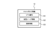
- FIG. 3 is a diagram showing an example of VN topology information held by the OpenFlow controller according to the present invention.
- FIG. 4 is a conceptual diagram of VN topology information held by the OpenFlow controller according to the present invention.
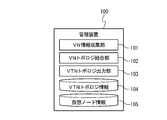
- FIG. 5 is a diagram showing a configuration in the embodiment of the management apparatus according to the present invention.
- FIG. 6 is a diagram showing an example of virtual node information held by the management apparatus according to the present invention.
- FIG. 7 is a diagram showing another example of the virtual node information held by the management apparatus according to the present invention.
- FIG. 8 is a diagram showing an example of VN topology information held by each of the plurality of OpenFlow controllers shown in FIG.
- FIG. 9 is a diagram showing an example of VTN topology information of the entire virtual network generated by integrating the VN topology information shown in FIG.
- FIG. 1 is a diagram showing the configuration of an embodiment of a computer system according to the present invention.
- the computer system according to the present invention performs communication path construction and packet data transfer control using OpenFlow.
- the computer system according to the present invention includes open flow controllers 1-1 to 1-5 (hereinafter referred to as OFC 1-1 to 1-5), a plurality of open flow switches 2 (hereinafter referred to as OFS2), and a plurality of L3 routers 3.
- a plurality of hosts 4 for example, storage 4-1, server 4-2, client terminal 4-3) and management apparatus 100 are provided. Note that the OFCs 1-1 to 1-5 are collectively referred to as OFC1 without distinction.
- the host 4 is a computer device including a CPU, a main storage device, and an external storage device (not shown), and communicates with other hosts 4 by executing a program stored in the external storage device. Communication between the hosts 4 is performed via the switch 2 or the L3 router 3.
- the host 4 realizes functions exemplified in the storage 4-1, server (for example, Web server, file server, application server), client terminal 4-3, and the like according to the program to be executed and its hardware structure.
- the OFC 1 includes a flow control unit 12 that controls communication path packet transfer processing related to packet transfer in the system using the open flow technology.
- the OpenFlow technology refers to a technology in which the controller (here OFC1) performs route control and node control by setting multi-layer and flow unit route information in OFS2 according to a routing policy (flow entry: flow + action). (For details, see Non-Patent Document 1.) As a result, the route control function is separated from the routers and switches, and optimal routing and traffic management are possible through centralized control by the controller.
- OFS2 to which the OpenFlow technology is applied, handles communication as a flow of END2END, not as a unit of packet or frame like a conventional router or switch.
- the OFC 1 controls the operation of the OFS 2 (for example, packet data relay operation) by setting a flow entry (rule + action) in a flow table (not shown) held by the OFS 2.
- the setting of the flow entry for OFS 2 by OFC 1 and the notification of the first packet (packet IN) from OFS 2 to OFC 13 are performed via control network 200 (hereinafter referred to as control NW 200).
- OFC 1-1 to 1-4 are installed as OFC1 for controlling the network (OFS2) in the data center DC1, and OFC1-5 is set as the OFC1 for controlling the network (OFS2) in the data center DC2. is set up.
- the OFCs 1-1 to 1-4 are connected to the OFS 2 in the data center DC1 via the control NW 200-1, and the OFC 1-5 is connected to the OFS 2 in the data center DC2 via the control NW 200-2.
- the network (OFS2) of the data center DC1 and the network (OFS2) of the data center DC2 are networks (sub-networks) of different IP address ranges connected via the L3 router 3 that performs routing in layer 3.
- FIG. 2 is a diagram showing the configuration of the OFC 1 according to the present invention.
- the OFC 1 is preferably realized by a computer including a CPU and a storage device.
- the functions of the VN topology information notification unit 11 and the flow control unit 12 illustrated in FIG. 2 are realized by a CPU (not shown) executing a program stored in a storage device.
- the OFC 1 holds VN topology information 13 stored in the storage device.
- the flow control unit 12 sets or deletes a flow entry (rule + action) in the OFS 2 managed by itself. At this time, the flow control unit 12 associates a controller ID for identifying the OFC 1 with the flow entry (rule + action information) and sets the flow ID in the OFS 2 flow table.
- the OFS 2 refers to the set flow entry and executes an action (for example, relay or discard of packet data) corresponding to the rule according to the header information of the received packet. Details of the rules and actions will be described later.
- a combination of layer 1 to layer 4 addresses and identifiers of an OSI (Open Systems Interconnection) reference model included in header information in TCP / IP packet data is defined.
- OSI Open Systems Interconnection
- each combination of a layer 1 physical port, a layer 2 MAC address, a VLAN tag (VLAN id), a layer 3 IP address, and a layer 4 port number is set as a rule.
- the VLAN tag may be given a priority (VLAN priority).
- identifiers such as port numbers and addresses set in the rules may be set within a predetermined range. Further, it is preferable that the destination and the address of the transmission source are distinguished and set as a rule. For example, a range of a MAC destination address, a range of a destination port number that specifies a connection destination application, and a range of a transmission source port number that specifies a connection source application are set as rules. Furthermore, an identifier for specifying the data transfer protocol may be set as a rule.
- a method for processing TCP / IP packet data is defined. For example, information indicating whether or not the received packet data is to be relayed and the transmission destination in the case of relaying are set. In the action, information instructing to copy or discard the packet data may be set.
- a preset virtual network (VN) is constructed for each OFC 1 by flow control by the OFC 1.
- one virtual tenant network (VTN) is constructed by at least one virtual network (VN) managed for each OFC 1.
- VTN1 is constructed by virtual networks managed by the OFCs 1-1 to 1-5 that control different IP networks.
- one virtual tenant network VTN2 may be constructed by virtual networks managed by the OFCs 1-1 to 1-4 that control the same IP network.
- a virtual network managed by one OFC1 (for example, OFC1-5) may constitute one virtual tenant network VTN3.
- a plurality of virtual tenant networks (VTN) may be constructed in the system.
- the VN topology information notification unit 11 notifies the management apparatus 100 of the VN topology information 13 of the virtual network (VN) managed by the VN topology information notification unit 11.
- the VN topology information 13 includes information regarding the topology of the virtual network (VN) managed (controlled) by the OFC 1, as shown in FIGS. 1, the computer system according to the present invention realizes a plurality of virtual tenant networks VTN1, VTN2,... By being controlled by a plurality of OFC1.
- the virtual tenant network includes a virtual network (VN) managed (controlled) by each of the OFCs 1-1 to 1-5.
- the OFC 1 holds, as VN topology information 13, information related to the topology of a virtual network managed by the OFC 1 (hereinafter referred to as a management target virtual network).
- FIG. 3 is a diagram illustrating an example of the VN topology information 13 held by the OFC 1.
- FIG. 4 is a conceptual diagram of the VN topology information 13 held by the OFC 1.
- the VN topology information 13 includes information regarding the connection status of virtual nodes in a virtual network realized by a physical switch such as the OFS 2 or a router (not shown).
- the VN topology information 13 includes information (virtual node information 132) for identifying a virtual node belonging to the management target virtual network, and connection information 133 indicating the connection status of the virtual node.
- the virtual node information 132 and the connection information 133 are recorded in association with a VTN number 131 that is an identifier of a virtual network (for example, a virtual tenant network) to which the managed virtual network belongs.
- the virtual node information 132 includes information specifying each of a virtual bridge, a virtual external, and a virtual router as a virtual node.
- the virtual external indicates a terminal (host) or router to which a virtual bridge is connected.
- the virtual node information 132 is defined by, for example, a combination of a VLAN name and a MAC address (or port number) to which the virtual node is connected.
- a virtual router identifier 132 (virtual router name) is associated with a MAC address (or port number) and set as virtual node information 132.
- the virtual node name exemplified in the virtual bridge name, the virtual external name, the virtual router name, etc. may be set uniquely for each OFC 1 as the virtual node information 132, or common to all OFCs 1 in the system. A name may be set.
- the connection information 133 includes information for specifying the connection destination of the virtual node, and is associated with the virtual node information 132 of the virtual node.
- virtual router (vRouter) “VR11” and virtual external (vExternal) “VE11” are set as connection information 133 as the connection destination of virtual bridge (vBridge) “VB11”.
- the connection information 133 may include a connection type (bridge / external / router / external network (L3 router)) for specifying a connection partner and information (for example, port number, MAC address, VLAN name) for specifying a connection destination.
- the VLAN name belonging to the virtual bridge is associated with the virtual bridge identifier (virtual bridge name) and set as connection information 133.
- the virtual external identifier (virtual external name) is set to VLAN.
- a combination of name and MAC address (or port number) is associated and set as connection information 133. That is, a virtual external is defined by a combination of VLAN name and MAC address (or port number).
- the virtual network shown in FIG. 4 belongs to the virtual tenant network VTN1, and includes a virtual router “VR11”, virtual bridges “VB11” and “VB12”, and virtual externals “VE11” and “VE12”.
- Virtual bridges “VB11” and “VB12” are separate sub-networks connected via a virtual router “VR11”.
- a virtual external “VE11” is connected to the virtual bridge “VB11”, and a MAC address of the virtual router “VR22” managed by the OFC1-2 “OFC2” is associated with the virtual external “VE11”.
- the VN topology information notification unit 11 notifies the management apparatus 100 of the VN topology information 13 managed by the VN topology information 13 via a secure management network 300 (hereinafter referred to as management NW 300).
- the management apparatus 100 combines the VN topology information 14 collected from the OFCs 1-1 to 1-5 based on the virtual node information 105, and creates a virtual network (for example, virtual tenant networks VTN1, VTN2, etc Of the entire system. Generate.
- FIG. 5 is a diagram showing a configuration in the embodiment of the management apparatus 100 according to the present invention.
- the management device 100 is preferably realized by a computer including a CPU and a storage device.
- the functions of the VN information collection unit 101, the VN topology combination unit 102, and the VTN topology output unit 103 shown in FIG. 5 are realized by executing a visualization program stored in a storage device by a CPU (not shown).
- the management apparatus 100 holds the VTN topology information 104 and the virtual node information 105 stored in the storage device.
- the VTN topology information 104 is not recorded in the initial state, but is recorded for the first time when it is generated by the VN topology coupling unit 102.
- the virtual node information 105 is preferably set in advance in the initial state.
- the VN information collection unit 101 issues a VN topology information collection instruction to the OFC 1 via the management NW 300, and acquires the VN topology information 13 from the OFC 1.
- the acquired VN topology information 13 is temporarily stored in a storage device (not shown).
- the VN topology combining unit 102 Based on the virtual node information 105, the VN topology combining unit 102 combines (integrates) the acquired VN topology information 13 in units of virtual networks (for example, in units of virtual tenants) in the entire system, and corresponds to the virtual networks in the entire system. Generate topology information.
- the topology information generated by the VN topology coupling unit 102 is recorded as VTN topology information 104 and is output so as to be visible by the VTN topology output unit 103.
- the VTN topology output unit 103 displays the VTN topology information 104 in a text format or graphically on an output device (not shown) such as a monitor.
- the VTN topology information 104 has the same configuration as the VN topology information 13 shown in FIG. 3, and includes virtual node information and connection information associated with the VTN number.
- the VN topology coupling unit 102 Based on the VN topology information 13 acquired from the OFC 1 and the virtual node information 105, the VN topology coupling unit 102 identifies a common (identical) virtual node among virtual nodes on the managed virtual network for each OFC 1. To do.
- the VN topology coupling unit 102 couples the virtual network to which the virtual node belongs via a common virtual node.
- the VN topology coupling unit 102 couples the virtual networks via a virtual bridge common to the networks.
- the VN topology combining unit 102 combines virtual networks via a virtual external common to the networks.
- the virtual node information 105 is information for associating a virtual node name uniquely assigned to each OFC 1 with respect to the same virtual node.
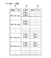
- FIG. 6 is a diagram showing an example of the virtual node information 105 held by the management apparatus 100 according to the present invention.
- the virtual node information 105 illustrated in FIG. 6 includes a controller name 51, a common virtual node name 52, and a corresponding virtual node name 53. Specifically, the virtual node name corresponding to the same virtual node among the virtual node names set for each OFC is recorded in association with the common virtual node name 52 as the corresponding virtual node name 53.
- FIG. 6 is a diagram showing an example of the virtual node information 105 held by the management apparatus 100 according to the present invention.
- the virtual node information 105 illustrated in FIG. 6 includes a controller name 51, a common virtual node name 52, and a corresponding virtual node name 53. Specifically, the virtual node name corresponding to the same virtual node among the virtual node names set for
- the virtual bridge “VBx1” set to the OFC1 with the controller name 51 “OFC1” and the virtual bridge “VBy1” set to the OFC1 of “OFC2” have the common virtual node name “VB1”.
- the VN topology coupling unit 102 refers to the virtual node information 105 using the controller name 51 and the corresponding virtual node name 53 as keys, so that the virtual bridge “included in the VN topology information 13 notified from the OFC1“ OFC1 ”“ It can be recognized that the virtual bridge “VBy1” included in the VN topology information 13 notified from VBx1 ”and OFC1“ OFC2 ”is the same virtual bridge“ VB1 ”.
- the VN topology coupling unit 102 refers to the virtual node information 105 illustrated in FIG. 6, so that the virtual bridge “VBx2” set by OFC1 “OFC1” and the virtual bridge “VBy2” set by OFC1 “OFC2” are displayed. "Can be recognized as the same virtual bridge” VB2 ".
- the virtual external “VEx1” set in OFC1 “OFC1” and the virtual external “VEx2” set in OFC1 “OFC2” are associated with the common virtual node name “VE1” as virtual node information 105. Is set.
- the VN topology coupling unit 102 is notified from the virtual external “VEx1” and the OFC1 “OFC2” included in the VN topology information 13 notified from the OFC1 “OFC1”. It can be recognized that the virtual external “VEy1” included in the VN topology information 13 is the same virtual external “VE1”. Similarly, by referring to the virtual node information 105 illustrated in FIG. 6, the VN topology coupling unit 102 causes the virtual external “VEx2” set by OFC1 “OFC1” and the virtual bridge “VEy2” set by OFC1 “OFC2”. "Can be recognized as the same virtual bridge” VE2 ".
- FIG. 7 is a diagram showing another example of the virtual node information 105 held by the management apparatus 100 according to the present invention.
- the virtual node information 105 illustrated in FIG. 7 includes a virtual node name 61, a VLAN name 62, and a MAC address 63. Specifically, the VLAN to which the virtual node belongs and the MAC address belonging to the virtual node are set as the virtual node information 105 in association with the name of the virtual node (virtual node name 61).
- the VN information collection unit 101 collects virtual node information 132 including the VLAN name to which the virtual node belongs and the MAC address belonging to the virtual node from the OFC 1.
- the VN topology coupling unit 102 refers to the virtual node information 105, specifies the virtual node name 61 using the VLAN name or MAC address included in the virtual node information 132 from the OFC 1 as a key, and is included in the virtual node information 132 Associate with virtual node name.
- the VN topology combining unit 102 recognizes virtual nodes having the same virtual node name 61 specified by the VLAN name or MAC address as the same virtual node even if the virtual node names acquired from other OFCs are different. can do.
- FIG. 8 is a diagram illustrating an example of the VN topology information 13 of the virtual network belonging to the virtual tenant network VTN1 held by each of the plurality of OFCs 1-1 to 1-5 illustrated in FIG.
- OFC1-1 “OFC1” holds virtual bridge “VB11” and virtual external “VE11” connected to each other as VN topology information 13 of the virtual network to be managed.
- the OFC1-2 “OFC2” holds the virtual router “VR21”, the virtual bridges “VB21”, “VB22”, the virtual external “VE21”, and “VE22” as the VN topology information 13 of the management target virtual network.
- Virtual bridges “VB21” and “VB22” indicate different sub-networks connected via the virtual router “VR21”.
- a virtual external “VE21” is connected to the virtual bridge “VB21”.
- a virtual external “VE22” is connected to the virtual bridge “VB22”, and an L3 router “SW1” is associated with the virtual external “VE22”.
- the OFC1-3 “OFC3” holds the virtual bridge “VB31”, the virtual external “VE31”, and “VE32” as the VN topology information 13 of the management target virtual network.
- the OFC1-4 “OFC4” holds a virtual bridge “VB41” and a virtual external “VE41” as the VN topology information 13 of its own management target virtual network.
- the OFC 1-5 “OFC 5” holds the virtual router “VR 51”, the virtual bridges “VB 51”, “VB 52”, the virtual external “VE 51”, and “VE 52” as the VN topology information 13 of the management target virtual network.
- Virtual bridges “VB51” and “VB52” indicate different sub-networks connected via the virtual router “VR51”.
- a virtual external “VE51” is connected to the virtual bridge “VB51”, and an L3 router “SW2” is associated with the virtual external “VE51”.
- a virtual external “VE52” is connected to the virtual bridge “VB52”.
- the VN information collection unit 101 of the management apparatus 100 issues a VN topology information collection instruction for the virtual tenant network “VTN1” to the OFCs 1-1 to 1-5.
- Each of the OFCs 1-1 to 1-5 notifies the management apparatus 100 of the VN topology information 13 belonging to the virtual tenant network “VTN1” via the management NW 300.
- the management apparatus 100 collects, for example, the VN topology information 13 shown in FIG. 8 from each of the OFCs 1-1 to 1-5.
- the VN topology coupling unit 102 of the management apparatus 100 refers to the virtual node information 105 and identifies a common virtual node in the collected VN topology information 13.
- virtual bridges “VB11”, “VB21”, “VB31”, and “VB41” are registered in association with each other as virtual bridges “VB1”, and virtual eternals “VE22” and “VB51” are registered. Are registered in association with each other as a virtual eternal “VE1”.
- the VN topology coupling unit 102 refers to the virtual node information 105, and when the virtual bridges on the two virtual networks are associated with each other, the VN topology coupling unit 102 regards that the virtual network is L2 connected. In this case, the VN topology coupling unit 102 couples the virtual network via the associated virtual bridge.
- the VN topology coupling unit 102 sets the corresponding virtual bridges “VB11”, “VB21”, “VB31”, and “VB41” as the same virtual bridge “VB1” based on the virtual node information 105, the virtual router “ Connect to VR21 ". Further, the VN topology coupling unit 102 refers to the virtual node information 105, and when the virtual externals on the two virtual networks are associated with each other, the VN topology coupling unit 102 considers that the virtual network is L3 connected. In this case, the VN topology coupling unit 102 couples the virtual network via the associated virtual external.
- the VN topology coupling unit 102 corresponds to the virtual eternals “VE22” and “VE51”, so that the virtual eternals “VE22” and “VE51” are the same virtual eternal “VE1”, the virtual bridges “VB22”, “ Connect between VB51 ".
- the VN topology combining unit 102 combines (integrates) the VN topology information 13 for each OFC1 shown in FIG. 8, and obtains the topology information (VTN topology information 104) of the entire virtual tenant network “VTN1” shown in FIG. Generate and record.
- the generated VTN topology information 104 is output so as to be visible as shown in FIG.
- the network manager can centrally manage the topology of the virtual network in the entire system shown in FIG.
- the management apparatus 100 shown in FIG. 1 is provided separately from the OFC 1, but is not limited thereto, and may be provided in any of the OFC 1-1 to OFC 1-5.
- the computer system is shown with five OFCs 1 provided, but the number of OFCs 1 connected to the network and the number of hosts 4 are not limited thereto.
Landscapes
- Engineering & Computer Science (AREA)
- Computer Networks & Wireless Communication (AREA)
- Signal Processing (AREA)
- Computer Security & Cryptography (AREA)
- Human Computer Interaction (AREA)
- Data Exchanges In Wide-Area Networks (AREA)
Priority Applications (4)
| Application Number | Priority Date | Filing Date | Title |
|---|---|---|---|
| JP2013557509A JP5967109B2 (ja) | 2012-02-10 | 2013-02-05 | コンピュータシステム、及び仮想ネットワークの可視化方法 |
| EP13747150.4A EP2814205A4 (fr) | 2012-02-10 | 2013-02-05 | Système informatique et procédé de visualisation de réseau virtuel |
| US14/377,469 US20150019756A1 (en) | 2012-02-10 | 2013-02-05 | Computer system and virtual network visualization method |
| CN201380008655.7A CN104106237B (zh) | 2012-02-10 | 2013-02-05 | 计算机系统和虚拟网络可视化方法 |
Applications Claiming Priority (2)
| Application Number | Priority Date | Filing Date | Title |
|---|---|---|---|
| JP2012-027779 | 2012-02-10 | ||
| JP2012027779 | 2012-02-10 |
Publications (1)
| Publication Number | Publication Date |
|---|---|
| WO2013118687A1 true WO2013118687A1 (fr) | 2013-08-15 |
Family
ID=48947451
Family Applications (1)
| Application Number | Title | Priority Date | Filing Date |
|---|---|---|---|
| PCT/JP2013/052523 Ceased WO2013118687A1 (fr) | 2012-02-10 | 2013-02-05 | Système informatique et procédé de visualisation de réseau virtuel |
Country Status (5)
| Country | Link |
|---|---|
| US (1) | US20150019756A1 (fr) |
| EP (1) | EP2814205A4 (fr) |
| JP (1) | JP5967109B2 (fr) |
| CN (1) | CN104106237B (fr) |
| WO (1) | WO2013118687A1 (fr) |
Cited By (1)
| Publication number | Priority date | Publication date | Assignee | Title |
|---|---|---|---|---|
| CN113824615A (zh) * | 2021-09-26 | 2021-12-21 | 济南浪潮数据技术有限公司 | 一种基于OpenFlow的虚拟网络流量可视化方法、装置及设备 |
Families Citing this family (64)
| Publication number | Priority date | Publication date | Assignee | Title |
|---|---|---|---|---|
| US9781004B2 (en) | 2014-10-16 | 2017-10-03 | Cisco Technology, Inc. | Discovering and grouping application endpoints in a network environment |
| US9800549B2 (en) | 2015-02-11 | 2017-10-24 | Cisco Technology, Inc. | Hierarchical clustering in a geographically dispersed network environment |
| CN104717095B (zh) * | 2015-03-17 | 2018-04-10 | 大连理工大学 | 一种集成多控制器的可视化sdn网络管理方法 |
| US9521071B2 (en) * | 2015-03-22 | 2016-12-13 | Freescale Semiconductor, Inc. | Federation of controllers management using packet context |
| US10440054B2 (en) * | 2015-09-25 | 2019-10-08 | Perspecta Labs Inc. | Customized information networks for deception and attack mitigation |
| US10826788B2 (en) | 2017-04-20 | 2020-11-03 | Cisco Technology, Inc. | Assurance of quality-of-service configurations in a network |
| US10623264B2 (en) | 2017-04-20 | 2020-04-14 | Cisco Technology, Inc. | Policy assurance for service chaining |
| US10560328B2 (en) | 2017-04-20 | 2020-02-11 | Cisco Technology, Inc. | Static network policy analysis for networks |
| US10623271B2 (en) | 2017-05-31 | 2020-04-14 | Cisco Technology, Inc. | Intra-priority class ordering of rules corresponding to a model of network intents |
| US10505816B2 (en) | 2017-05-31 | 2019-12-10 | Cisco Technology, Inc. | Semantic analysis to detect shadowing of rules in a model of network intents |
| US10812318B2 (en) | 2017-05-31 | 2020-10-20 | Cisco Technology, Inc. | Associating network policy objects with specific faults corresponding to fault localizations in large-scale network deployment |
| US10693738B2 (en) | 2017-05-31 | 2020-06-23 | Cisco Technology, Inc. | Generating device-level logical models for a network |
| US20180351788A1 (en) | 2017-05-31 | 2018-12-06 | Cisco Technology, Inc. | Fault localization in large-scale network policy deployment |
| US10554483B2 (en) | 2017-05-31 | 2020-02-04 | Cisco Technology, Inc. | Network policy analysis for networks |
| US10439875B2 (en) | 2017-05-31 | 2019-10-08 | Cisco Technology, Inc. | Identification of conflict rules in a network intent formal equivalence failure |
| US10581694B2 (en) | 2017-05-31 | 2020-03-03 | Cisco Technology, Inc. | Generation of counter examples for network intent formal equivalence failures |
| US11469986B2 (en) | 2017-06-16 | 2022-10-11 | Cisco Technology, Inc. | Controlled micro fault injection on a distributed appliance |
| US11150973B2 (en) | 2017-06-16 | 2021-10-19 | Cisco Technology, Inc. | Self diagnosing distributed appliance |
| US10686669B2 (en) | 2017-06-16 | 2020-06-16 | Cisco Technology, Inc. | Collecting network models and node information from a network |
| US10904101B2 (en) | 2017-06-16 | 2021-01-26 | Cisco Technology, Inc. | Shim layer for extracting and prioritizing underlying rules for modeling network intents |
| US10547715B2 (en) | 2017-06-16 | 2020-01-28 | Cisco Technology, Inc. | Event generation in response to network intent formal equivalence failures |
| US10587621B2 (en) | 2017-06-16 | 2020-03-10 | Cisco Technology, Inc. | System and method for migrating to and maintaining a white-list network security model |
| US10574513B2 (en) | 2017-06-16 | 2020-02-25 | Cisco Technology, Inc. | Handling controller and node failure scenarios during data collection |
| US10498608B2 (en) | 2017-06-16 | 2019-12-03 | Cisco Technology, Inc. | Topology explorer |
| US11645131B2 (en) | 2017-06-16 | 2023-05-09 | Cisco Technology, Inc. | Distributed fault code aggregation across application centric dimensions |
| US10554493B2 (en) | 2017-06-19 | 2020-02-04 | Cisco Technology, Inc. | Identifying mismatches between a logical model and node implementation |
| US10432467B2 (en) | 2017-06-19 | 2019-10-01 | Cisco Technology, Inc. | Network validation between the logical level and the hardware level of a network |
| US10652102B2 (en) | 2017-06-19 | 2020-05-12 | Cisco Technology, Inc. | Network node memory utilization analysis |
| US10536337B2 (en) | 2017-06-19 | 2020-01-14 | Cisco Technology, Inc. | Validation of layer 2 interface and VLAN in a networked environment |
| US10673702B2 (en) | 2017-06-19 | 2020-06-02 | Cisco Technology, Inc. | Validation of layer 3 using virtual routing forwarding containers in a network |
| US10437641B2 (en) | 2017-06-19 | 2019-10-08 | Cisco Technology, Inc. | On-demand processing pipeline interleaved with temporal processing pipeline |
| US10348564B2 (en) | 2017-06-19 | 2019-07-09 | Cisco Technology, Inc. | Validation of routing information base-forwarding information base equivalence in a network |
| US10700933B2 (en) | 2017-06-19 | 2020-06-30 | Cisco Technology, Inc. | Validating tunnel endpoint addresses in a network fabric |
| US10812336B2 (en) | 2017-06-19 | 2020-10-20 | Cisco Technology, Inc. | Validation of bridge domain-L3out association for communication outside a network |
| US10333787B2 (en) | 2017-06-19 | 2019-06-25 | Cisco Technology, Inc. | Validation of L3OUT configuration for communications outside a network |
| US11343150B2 (en) | 2017-06-19 | 2022-05-24 | Cisco Technology, Inc. | Validation of learned routes in a network |
| US10411996B2 (en) | 2017-06-19 | 2019-09-10 | Cisco Technology, Inc. | Validation of routing information in a network fabric |
| US10567228B2 (en) | 2017-06-19 | 2020-02-18 | Cisco Technology, Inc. | Validation of cross logical groups in a network |
| US10560355B2 (en) | 2017-06-19 | 2020-02-11 | Cisco Technology, Inc. | Static endpoint validation |
| US10644946B2 (en) | 2017-06-19 | 2020-05-05 | Cisco Technology, Inc. | Detection of overlapping subnets in a network |
| US10528444B2 (en) | 2017-06-19 | 2020-01-07 | Cisco Technology, Inc. | Event generation in response to validation between logical level and hardware level |
| US10341184B2 (en) | 2017-06-19 | 2019-07-02 | Cisco Technology, Inc. | Validation of layer 3 bridge domain subnets in in a network |
| US10805160B2 (en) | 2017-06-19 | 2020-10-13 | Cisco Technology, Inc. | Endpoint bridge domain subnet validation |
| US10567229B2 (en) | 2017-06-19 | 2020-02-18 | Cisco Technology, Inc. | Validating endpoint configurations between nodes |
| US10505817B2 (en) | 2017-06-19 | 2019-12-10 | Cisco Technology, Inc. | Automatically determining an optimal amount of time for analyzing a distributed network environment |
| US10218572B2 (en) | 2017-06-19 | 2019-02-26 | Cisco Technology, Inc. | Multiprotocol border gateway protocol routing validation |
| US10623259B2 (en) | 2017-06-19 | 2020-04-14 | Cisco Technology, Inc. | Validation of layer 1 interface in a network |
| US11283680B2 (en) | 2017-06-19 | 2022-03-22 | Cisco Technology, Inc. | Identifying components for removal in a network configuration |
| US10587456B2 (en) | 2017-09-12 | 2020-03-10 | Cisco Technology, Inc. | Event clustering for a network assurance platform |
| US10587484B2 (en) | 2017-09-12 | 2020-03-10 | Cisco Technology, Inc. | Anomaly detection and reporting in a network assurance appliance |
| US10554477B2 (en) | 2017-09-13 | 2020-02-04 | Cisco Technology, Inc. | Network assurance event aggregator |
| US10333833B2 (en) | 2017-09-25 | 2019-06-25 | Cisco Technology, Inc. | Endpoint path assurance |
| US11102053B2 (en) | 2017-12-05 | 2021-08-24 | Cisco Technology, Inc. | Cross-domain assurance |
| US10873509B2 (en) | 2018-01-17 | 2020-12-22 | Cisco Technology, Inc. | Check-pointing ACI network state and re-execution from a check-pointed state |
| US10572495B2 (en) | 2018-02-06 | 2020-02-25 | Cisco Technology Inc. | Network assurance database version compatibility |
| US10812315B2 (en) | 2018-06-07 | 2020-10-20 | Cisco Technology, Inc. | Cross-domain network assurance |
| US10659298B1 (en) | 2018-06-27 | 2020-05-19 | Cisco Technology, Inc. | Epoch comparison for network events |
| US11044273B2 (en) | 2018-06-27 | 2021-06-22 | Cisco Technology, Inc. | Assurance of security rules in a network |
| US11019027B2 (en) | 2018-06-27 | 2021-05-25 | Cisco Technology, Inc. | Address translation for external network appliance |
| US11218508B2 (en) | 2018-06-27 | 2022-01-04 | Cisco Technology, Inc. | Assurance of security rules in a network |
| US10911495B2 (en) | 2018-06-27 | 2021-02-02 | Cisco Technology, Inc. | Assurance of security rules in a network |
| US10904070B2 (en) | 2018-07-11 | 2021-01-26 | Cisco Technology, Inc. | Techniques and interfaces for troubleshooting datacenter networks |
| US10826770B2 (en) | 2018-07-26 | 2020-11-03 | Cisco Technology, Inc. | Synthesis of models for networks using automated boolean learning |
| US10616072B1 (en) | 2018-07-27 | 2020-04-07 | Cisco Technology, Inc. | Epoch data interface |
Citations (7)
| Publication number | Priority date | Publication date | Assignee | Title |
|---|---|---|---|---|
| US5948055A (en) * | 1996-08-29 | 1999-09-07 | Hewlett-Packard Company | Distributed internet monitoring system and method |
| JP2006019866A (ja) * | 2004-06-30 | 2006-01-19 | Fujitsu Ltd | 伝送装置 |
| WO2011083780A1 (fr) * | 2010-01-05 | 2011-07-14 | 日本電気株式会社 | Système de communication, appareil de commande, procédé d'établissement de règle de traitement, procédé de transmission de paquet et programme |
| JP2011160363A (ja) | 2010-02-03 | 2011-08-18 | Nec Corp | コンピュータシステム、コントローラ、スイッチ、及び通信方法 |
| JP2011166384A (ja) | 2010-02-08 | 2011-08-25 | Nec Corp | コンピュータシステム、及び通信方法 |
| JP2011166692A (ja) | 2010-02-15 | 2011-08-25 | Nec Corp | ネットワークシステム、ネットワーク機器、経路情報更新方法、及びプログラム |
| JP2012027779A (ja) | 2010-07-26 | 2012-02-09 | Denso Corp | 運転支援車載装置及び路車間通信システム |
Family Cites Families (28)
| Publication number | Priority date | Publication date | Assignee | Title |
|---|---|---|---|---|
| US7752024B2 (en) * | 2000-05-05 | 2010-07-06 | Computer Associates Think, Inc. | Systems and methods for constructing multi-layer topological models of computer networks |
| US20030115319A1 (en) * | 2001-12-17 | 2003-06-19 | Dawson Jeffrey L. | Network paths |
| US7219300B2 (en) * | 2002-09-30 | 2007-05-15 | Sanavigator, Inc. | Method and system for generating a network monitoring display with animated utilization information |
| EP1570604A4 (fr) * | 2002-12-13 | 2008-05-07 | Internap Network Services Corp | Commande d'acheminement tenant compte de la topologie |
| US8627005B1 (en) * | 2004-03-26 | 2014-01-07 | Emc Corporation | System and method for virtualization of networked storage resources |
| US7681130B1 (en) * | 2006-03-31 | 2010-03-16 | Emc Corporation | Methods and apparatus for displaying network data |
| US10313191B2 (en) * | 2007-08-31 | 2019-06-04 | Level 3 Communications, Llc | System and method for managing virtual local area networks |
| US8161393B2 (en) * | 2007-09-18 | 2012-04-17 | International Business Machines Corporation | Arrangements for managing processing components using a graphical user interface |
| EP2582091B1 (fr) * | 2007-09-26 | 2017-05-31 | Nicira Inc. | Système d'exploitation de réseau pour la gestion et la sécurisation des réseaux |
| US8447181B2 (en) * | 2008-08-15 | 2013-05-21 | Tellabs Operations, Inc. | Method and apparatus for displaying and identifying available wavelength paths across a network |
| US8255496B2 (en) * | 2008-12-30 | 2012-08-28 | Juniper Networks, Inc. | Method and apparatus for determining a network topology during network provisioning |
| US8213336B2 (en) * | 2009-02-23 | 2012-07-03 | Cisco Technology, Inc. | Distributed data center access switch |
| US7937438B1 (en) * | 2009-12-07 | 2011-05-03 | Amazon Technologies, Inc. | Using virtual networking devices to manage external connections |
| US8612627B1 (en) * | 2010-03-03 | 2013-12-17 | Amazon Technologies, Inc. | Managing encoded multi-part communications for provided computer networks |
| US8407366B2 (en) * | 2010-05-14 | 2013-03-26 | Microsoft Corporation | Interconnecting members of a virtual network |
| US8743889B2 (en) * | 2010-07-06 | 2014-06-03 | Nicira, Inc. | Method and apparatus for using a network information base to control a plurality of shared network infrastructure switching elements |
| WO2012083079A2 (fr) * | 2010-12-15 | 2012-06-21 | ZanttZ, Inc. | Moteur de simulation réseau |
| US8625597B2 (en) * | 2011-01-07 | 2014-01-07 | Jeda Networks, Inc. | Methods, systems and apparatus for the interconnection of fibre channel over ethernet devices |
| EP2673712B1 (fr) * | 2011-02-09 | 2024-01-17 | Vertiv IT Systems, Inc. | Système et procédé de structure de commande d'infrastructure |
| US9043452B2 (en) * | 2011-05-04 | 2015-05-26 | Nicira, Inc. | Network control apparatus and method for port isolation |
| US9288081B2 (en) * | 2011-08-17 | 2016-03-15 | Nicira, Inc. | Connecting unmanaged segmented networks by managing interconnection switching elements |
| US8593958B2 (en) * | 2011-09-14 | 2013-11-26 | Telefonaktiebologet L M Ericsson (Publ) | Network-wide flow monitoring in split architecture networks |
| US9154433B2 (en) * | 2011-10-25 | 2015-10-06 | Nicira, Inc. | Physical controller |
| US9337931B2 (en) * | 2011-11-01 | 2016-05-10 | Plexxi Inc. | Control and provisioning in a data center network with at least one central controller |
| US9311160B2 (en) * | 2011-11-10 | 2016-04-12 | Verizon Patent And Licensing Inc. | Elastic cloud networking |
| US9195491B2 (en) * | 2011-11-15 | 2015-11-24 | Nicira, Inc. | Migrating middlebox state for distributed middleboxes |
| US8824274B1 (en) * | 2011-12-29 | 2014-09-02 | Juniper Networks, Inc. | Scheduled network layer programming within a multi-topology computer network |
| US8948054B2 (en) * | 2011-12-30 | 2015-02-03 | Cisco Technology, Inc. | System and method for discovering multipoint endpoints in a network environment |
-
2013
- 2013-02-05 WO PCT/JP2013/052523 patent/WO2013118687A1/fr not_active Ceased
- 2013-02-05 JP JP2013557509A patent/JP5967109B2/ja not_active Expired - Fee Related
- 2013-02-05 EP EP13747150.4A patent/EP2814205A4/fr not_active Withdrawn
- 2013-02-05 CN CN201380008655.7A patent/CN104106237B/zh not_active Expired - Fee Related
- 2013-02-05 US US14/377,469 patent/US20150019756A1/en not_active Abandoned
Patent Citations (7)
| Publication number | Priority date | Publication date | Assignee | Title |
|---|---|---|---|---|
| US5948055A (en) * | 1996-08-29 | 1999-09-07 | Hewlett-Packard Company | Distributed internet monitoring system and method |
| JP2006019866A (ja) * | 2004-06-30 | 2006-01-19 | Fujitsu Ltd | 伝送装置 |
| WO2011083780A1 (fr) * | 2010-01-05 | 2011-07-14 | 日本電気株式会社 | Système de communication, appareil de commande, procédé d'établissement de règle de traitement, procédé de transmission de paquet et programme |
| JP2011160363A (ja) | 2010-02-03 | 2011-08-18 | Nec Corp | コンピュータシステム、コントローラ、スイッチ、及び通信方法 |
| JP2011166384A (ja) | 2010-02-08 | 2011-08-25 | Nec Corp | コンピュータシステム、及び通信方法 |
| JP2011166692A (ja) | 2010-02-15 | 2011-08-25 | Nec Corp | ネットワークシステム、ネットワーク機器、経路情報更新方法、及びプログラム |
| JP2012027779A (ja) | 2010-07-26 | 2012-02-09 | Denso Corp | 運転支援車載装置及び路車間通信システム |
Non-Patent Citations (3)
| Title |
|---|
| "Toshindan no OpenFlow Part 2 [Data Center deno Katsuyo Scene] VLAN, Multi Tenant, ''Mieru-ka'' Kizon Gijutsu ga Kakaeru Kadai o Kaiketsu", NIKKEI COMMUNICATIONS, 1 February 2012 (2012-02-01), pages 20 - 23, XP008174778 * |
| OPENFLOW SWITCH SPECIFICATION VERSION 1.1.0 IMPLEMENTED (WIRE PROTOCOL OX02, 28 February 2011 (2011-02-28) |
| See also references of EP2814205A4 |
Cited By (1)
| Publication number | Priority date | Publication date | Assignee | Title |
|---|---|---|---|---|
| CN113824615A (zh) * | 2021-09-26 | 2021-12-21 | 济南浪潮数据技术有限公司 | 一种基于OpenFlow的虚拟网络流量可视化方法、装置及设备 |
Also Published As
| Publication number | Publication date |
|---|---|
| JP5967109B2 (ja) | 2016-08-10 |
| EP2814205A4 (fr) | 2015-09-16 |
| CN104106237A (zh) | 2014-10-15 |
| US20150019756A1 (en) | 2015-01-15 |
| EP2814205A1 (fr) | 2014-12-17 |
| CN104106237B (zh) | 2017-08-11 |
| JPWO2013118687A1 (ja) | 2015-05-11 |
Similar Documents
| Publication | Publication Date | Title |
|---|---|---|
| JP5967109B2 (ja) | コンピュータシステム、及び仮想ネットワークの可視化方法 | |
| JP5811196B2 (ja) | コンピュータシステム、及び仮想ネットワークの可視化方法 | |
| CN103262472B (zh) | 计算机系统、控制器、控制器管理器和通信路由分析方法 | |
| JP5300076B2 (ja) | コンピュータシステム、及びコンピュータシステムの監視方法 | |
| JP5534037B2 (ja) | 情報システム、制御装置、仮想ネットワークの提供方法およびプログラム | |
| US7941539B2 (en) | Method and system for creating a virtual router in a blade chassis to maintain connectivity | |
| CN104639372B (zh) | 基于sdn的覆盖网络和物理网络的关联方法及系统 | |
| JP5757552B2 (ja) | コンピュータシステム、コントローラ、サービス提供サーバ、及び負荷分散方法 | |
| JP5488979B2 (ja) | コンピュータシステム、コントローラ、スイッチ、及び通信方法 | |
| WO2021047011A1 (fr) | Procédé et appareil de traitement de données et support d'enregistrement informatique | |
| CN102857416A (zh) | 一种实现虚拟网络的方法和虚拟网络 | |
| JP2014036240A (ja) | 制御装置、方法及びプログラム、並びにシステム及び情報処理方法 | |
| JP5861772B2 (ja) | ネットワークアプライアンス冗長化システム、制御装置、ネットワークアプライアンス冗長化方法及びプログラム | |
| JPWO2014054691A1 (ja) | 通信システム、制御装置、制御方法及びプログラム | |
| Kumar et al. | Open flow switch with intrusion detection system | |
| WO2016068238A1 (fr) | Système de commande de réseau, dispositif de commande, procédé de gestion d'informations de réseau, et programme | |
| JP2017175522A (ja) | ネットワークシステム、制御装置、方法およびプログラム | |
| KR101527373B1 (ko) | Sdn 기반의 분할 계층적 네트워크 시스템 | |
| JP5854488B2 (ja) | 通信システム、制御装置、処理規則の設定方法およびプログラム | |
| JP5716107B1 (ja) | ノード検出システム及び方法及び仮想ノードの機能制御装置及び方法 | |
| JP2015226235A (ja) | ネットワーク輻輳回避システム及び方法 | |
| Scicluna | Automotive factory network renewal | |
| JP2016225933A (ja) | 制御装置、中継装置の制御方法、プログラム及び通信システム | |
| Abaev et al. | Analytical model for Software Defined Network delay estimation |
Legal Events
| Date | Code | Title | Description |
|---|---|---|---|
| 121 | Ep: the epo has been informed by wipo that ep was designated in this application |
Ref document number: 13747150 Country of ref document: EP Kind code of ref document: A1 |
|
| ENP | Entry into the national phase |
Ref document number: 2013557509 Country of ref document: JP Kind code of ref document: A |
|
| WWE | Wipo information: entry into national phase |
Ref document number: 14377469 Country of ref document: US |
|
| WWE | Wipo information: entry into national phase |
Ref document number: 2013747150 Country of ref document: EP |
|
| NENP | Non-entry into the national phase |
Ref country code: DE |