WO2013121517A1 - Dispositif de commande pour moteur à combustion interne - Google Patents
Dispositif de commande pour moteur à combustion interne Download PDFInfo
- Publication number
- WO2013121517A1 WO2013121517A1 PCT/JP2012/053360 JP2012053360W WO2013121517A1 WO 2013121517 A1 WO2013121517 A1 WO 2013121517A1 JP 2012053360 W JP2012053360 W JP 2012053360W WO 2013121517 A1 WO2013121517 A1 WO 2013121517A1
- Authority
- WO
- WIPO (PCT)
- Prior art keywords
- egr
- pressure
- temperature
- compressor
- amount
- Prior art date
- Legal status (The legal status is an assumption and is not a legal conclusion. Google has not performed a legal analysis and makes no representation as to the accuracy of the status listed.)
- Ceased
Links
Images





Classifications
-
- F—MECHANICAL ENGINEERING; LIGHTING; HEATING; WEAPONS; BLASTING
- F02—COMBUSTION ENGINES; HOT-GAS OR COMBUSTION-PRODUCT ENGINE PLANTS
- F02B—INTERNAL-COMBUSTION PISTON ENGINES; COMBUSTION ENGINES IN GENERAL
- F02B39/00—Component parts, details, or accessories relating to, driven charging or scavenging pumps, not provided for in groups F02B33/00 - F02B37/00
- F02B39/16—Other safety measures for, or other control of, pumps
-
- F—MECHANICAL ENGINEERING; LIGHTING; HEATING; WEAPONS; BLASTING
- F01—MACHINES OR ENGINES IN GENERAL; ENGINE PLANTS IN GENERAL; STEAM ENGINES
- F01M—LUBRICATING OF MACHINES OR ENGINES IN GENERAL; LUBRICATING INTERNAL COMBUSTION ENGINES; CRANKCASE VENTILATING
- F01M11/00—Component parts, details or accessories, not provided for in, or of interest apart from, groups F01M1/00 - F01M9/00
- F01M11/10—Indicating devices; Other safety devices
-
- F—MECHANICAL ENGINEERING; LIGHTING; HEATING; WEAPONS; BLASTING
- F02—COMBUSTION ENGINES; HOT-GAS OR COMBUSTION-PRODUCT ENGINE PLANTS
- F02D—CONTROLLING COMBUSTION ENGINES
- F02D23/00—Controlling engines characterised by their being supercharged
- F02D23/02—Controlling engines characterised by their being supercharged the engines being of fuel-injection type
-
- F—MECHANICAL ENGINEERING; LIGHTING; HEATING; WEAPONS; BLASTING
- F02—COMBUSTION ENGINES; HOT-GAS OR COMBUSTION-PRODUCT ENGINE PLANTS
- F02D—CONTROLLING COMBUSTION ENGINES
- F02D41/00—Electrical control of supply of combustible mixture or its constituents
- F02D41/0002—Controlling intake air
- F02D41/0007—Controlling intake air for control of turbo-charged or super-charged engines
-
- F—MECHANICAL ENGINEERING; LIGHTING; HEATING; WEAPONS; BLASTING
- F02—COMBUSTION ENGINES; HOT-GAS OR COMBUSTION-PRODUCT ENGINE PLANTS
- F02D—CONTROLLING COMBUSTION ENGINES
- F02D41/00—Electrical control of supply of combustible mixture or its constituents
- F02D41/0025—Controlling engines characterised by use of non-liquid fuels, pluralities of fuels, or non-fuel substances added to the combustible mixtures
- F02D41/0047—Controlling exhaust gas recirculation [EGR]
- F02D41/0065—Specific aspects of external EGR control
- F02D41/0072—Estimating, calculating or determining the EGR rate, amount or flow
-
- F—MECHANICAL ENGINEERING; LIGHTING; HEATING; WEAPONS; BLASTING
- F02—COMBUSTION ENGINES; HOT-GAS OR COMBUSTION-PRODUCT ENGINE PLANTS
- F02M—SUPPLYING COMBUSTION ENGINES IN GENERAL WITH COMBUSTIBLE MIXTURES OR CONSTITUENTS THEREOF
- F02M26/00—Engine-pertinent apparatus for adding exhaust gases to combustion-air, main fuel or fuel-air mixture, e.g. by exhaust gas recirculation [EGR] systems
- F02M26/13—Arrangement or layout of EGR passages, e.g. in relation to specific engine parts or for incorporation of accessories
- F02M26/14—Arrangement or layout of EGR passages, e.g. in relation to specific engine parts or for incorporation of accessories in relation to the exhaust system
- F02M26/15—Arrangement or layout of EGR passages, e.g. in relation to specific engine parts or for incorporation of accessories in relation to the exhaust system in relation to engine exhaust purifying apparatus
-
- F—MECHANICAL ENGINEERING; LIGHTING; HEATING; WEAPONS; BLASTING
- F02—COMBUSTION ENGINES; HOT-GAS OR COMBUSTION-PRODUCT ENGINE PLANTS
- F02M—SUPPLYING COMBUSTION ENGINES IN GENERAL WITH COMBUSTIBLE MIXTURES OR CONSTITUENTS THEREOF
- F02M26/00—Engine-pertinent apparatus for adding exhaust gases to combustion-air, main fuel or fuel-air mixture, e.g. by exhaust gas recirculation [EGR] systems
- F02M26/45—Sensors specially adapted for EGR systems
- F02M26/46—Sensors specially adapted for EGR systems for determining the characteristics of gases, e.g. composition
- F02M26/47—Sensors specially adapted for EGR systems for determining the characteristics of gases, e.g. composition the characteristics being temperatures, pressures or flow rates
-
- F—MECHANICAL ENGINEERING; LIGHTING; HEATING; WEAPONS; BLASTING
- F02—COMBUSTION ENGINES; HOT-GAS OR COMBUSTION-PRODUCT ENGINE PLANTS
- F02M—SUPPLYING COMBUSTION ENGINES IN GENERAL WITH COMBUSTIBLE MIXTURES OR CONSTITUENTS THEREOF
- F02M26/00—Engine-pertinent apparatus for adding exhaust gases to combustion-air, main fuel or fuel-air mixture, e.g. by exhaust gas recirculation [EGR] systems
- F02M26/50—Arrangements or methods for preventing or reducing deposits, corrosion or wear caused by impurities
-
- F—MECHANICAL ENGINEERING; LIGHTING; HEATING; WEAPONS; BLASTING
- F02—COMBUSTION ENGINES; HOT-GAS OR COMBUSTION-PRODUCT ENGINE PLANTS
- F02B—INTERNAL-COMBUSTION PISTON ENGINES; COMBUSTION ENGINES IN GENERAL
- F02B39/00—Component parts, details, or accessories relating to, driven charging or scavenging pumps, not provided for in groups F02B33/00 - F02B37/00
- F02B39/16—Other safety measures for, or other control of, pumps
- F02B2039/162—Control of pump parameters to improve safety thereof
- F02B2039/164—Control of pump parameters to improve safety thereof the temperature of the pump, of the pump drive or the pumped fluid being limited
-
- F—MECHANICAL ENGINEERING; LIGHTING; HEATING; WEAPONS; BLASTING
- F02—COMBUSTION ENGINES; HOT-GAS OR COMBUSTION-PRODUCT ENGINE PLANTS
- F02D—CONTROLLING COMBUSTION ENGINES
- F02D2200/00—Input parameters for engine control
- F02D2200/02—Input parameters for engine control the parameters being related to the engine
- F02D2200/04—Engine intake system parameters
- F02D2200/0414—Air temperature
-
- F—MECHANICAL ENGINEERING; LIGHTING; HEATING; WEAPONS; BLASTING
- F02—COMBUSTION ENGINES; HOT-GAS OR COMBUSTION-PRODUCT ENGINE PLANTS
- F02M—SUPPLYING COMBUSTION ENGINES IN GENERAL WITH COMBUSTIBLE MIXTURES OR CONSTITUENTS THEREOF
- F02M26/00—Engine-pertinent apparatus for adding exhaust gases to combustion-air, main fuel or fuel-air mixture, e.g. by exhaust gas recirculation [EGR] systems
- F02M26/02—EGR systems specially adapted for supercharged engines
- F02M26/04—EGR systems specially adapted for supercharged engines with a single turbocharger
- F02M26/05—High pressure loops, i.e. wherein recirculated exhaust gas is taken out from the exhaust system upstream of the turbine and reintroduced into the intake system downstream of the compressor
-
- F—MECHANICAL ENGINEERING; LIGHTING; HEATING; WEAPONS; BLASTING
- F02—COMBUSTION ENGINES; HOT-GAS OR COMBUSTION-PRODUCT ENGINE PLANTS
- F02M—SUPPLYING COMBUSTION ENGINES IN GENERAL WITH COMBUSTIBLE MIXTURES OR CONSTITUENTS THEREOF
- F02M26/00—Engine-pertinent apparatus for adding exhaust gases to combustion-air, main fuel or fuel-air mixture, e.g. by exhaust gas recirculation [EGR] systems
- F02M26/02—EGR systems specially adapted for supercharged engines
- F02M26/04—EGR systems specially adapted for supercharged engines with a single turbocharger
- F02M26/06—Low pressure loops, i.e. wherein recirculated exhaust gas is taken out from the exhaust downstream of the turbocharger turbine and reintroduced into the intake system upstream of the compressor
-
- Y—GENERAL TAGGING OF NEW TECHNOLOGICAL DEVELOPMENTS; GENERAL TAGGING OF CROSS-SECTIONAL TECHNOLOGIES SPANNING OVER SEVERAL SECTIONS OF THE IPC; TECHNICAL SUBJECTS COVERED BY FORMER USPC CROSS-REFERENCE ART COLLECTIONS [XRACs] AND DIGESTS
- Y02—TECHNOLOGIES OR APPLICATIONS FOR MITIGATION OR ADAPTATION AGAINST CLIMATE CHANGE
- Y02T—CLIMATE CHANGE MITIGATION TECHNOLOGIES RELATED TO TRANSPORTATION
- Y02T10/00—Road transport of goods or passengers
- Y02T10/10—Internal combustion engine [ICE] based vehicles
- Y02T10/12—Improving ICE efficiencies
-
- Y—GENERAL TAGGING OF NEW TECHNOLOGICAL DEVELOPMENTS; GENERAL TAGGING OF CROSS-SECTIONAL TECHNOLOGIES SPANNING OVER SEVERAL SECTIONS OF THE IPC; TECHNICAL SUBJECTS COVERED BY FORMER USPC CROSS-REFERENCE ART COLLECTIONS [XRACs] AND DIGESTS
- Y02—TECHNOLOGIES OR APPLICATIONS FOR MITIGATION OR ADAPTATION AGAINST CLIMATE CHANGE
- Y02T—CLIMATE CHANGE MITIGATION TECHNOLOGIES RELATED TO TRANSPORTATION
- Y02T10/00—Road transport of goods or passengers
- Y02T10/10—Internal combustion engine [ICE] based vehicles
- Y02T10/40—Engine management systems
Definitions
- the present invention relates to a control device for an internal combustion engine represented by an automobile engine or the like.
- the present invention relates to an improvement for maintaining high performance of an internal combustion engine provided with a supercharging device.
- a supercharging device (hereinafter sometimes referred to as a “turbocharger”) mounted on an automobile engine
- intake air is supercharged into a cylinder by rotation of a compressor wheel provided in an intake passage.
- the temperature of the intake air rises.
- the temperature of the compressor wheel and the like also rises.
- exhaust gas is recirculated from an exhaust passage downstream of a turbocharger turbine to an intake passage upstream of a turbocharger compressor.
- LPL Low Pressure Loop
- the deposits described above are attached. That is, in an engine equipped with this LPL-EGR mechanism, there is a possibility that oil is contained in the EGR gas recirculated to the intake passage upstream of the compressor, and the intake air (fresh air) flowing into the compressor Since the temperature of the air-fuel mixture with the high-temperature EGR gas) is relatively high, the oil is exposed to high temperatures when the intake air is supercharged.
- Patent Document 2 has been proposed as a technique for suppressing the occurrence of deposits in this compressor.
- the inside of the crankcase is controlled to be at atmospheric pressure, and the flow rate of the blow-by gas is set as much as possible. It is disclosed to reduce.
- the turbocharger supercharging efficiency may be reduced and the engine output may be reduced.
- the NOx amount in the exhaust gas may increase accordingly. This is because, in general, feedback control for maintaining the air-fuel ratio of the exhaust gas at the target air-fuel ratio is performed in the engine, so that the EGR gas amount decreases when the supercharging pressure decreases at the same air-fuel ratio. .
- the present invention has been made in view of such points, and an object of the present invention is to increase the supercharging pressure to the maximum while suppressing generation of deposits with respect to an internal combustion engine equipped with a supercharging device.
- An object of the present invention is to provide a control device for an internal combustion engine that can perform the above-described operation.
- the solution principle of the present invention taken to achieve the above object is to obtain the allowable upper limit temperature on the compressor outlet side where no deposit is generated or the allowable upper limit temperature of the compressor itself from the degree of deterioration of the oil. Based on the upper limit temperature, a supercharging pressure allowable upper limit value in the supercharging device is set to control the supercharging device. Further, when the EGR system is provided, the EGR rate is properly maintained when the EGR rate changes by controlling the supercharging pressure below the allowable upper limit of the supercharging pressure. Thus, the control of the EGR system is executed together.
- the present invention presupposes a control device for an internal combustion engine in which a compressor for a supercharging device is provided in an intake system.
- a compressor for a supercharging device is provided in an intake system.
- the supercharging pressure of the supercharging device is controlled.
- the temperature (the intake air temperature on the compressor outlet side or the temperature of the compressor component) for suppressing the occurrence of this deposit can be determined based on the degree of deterioration of the oil. Further, the temperature of the intake air accompanying supercharging by the supercharging device increases as the supercharging pressure increases. That is, the temperature of the supercharged intake air (temperature on the compressor outlet side) and the temperature of the compressor itself are correlated with the supercharging pressure in the supercharging device.
- the supercharging pressure in the supercharging device is appropriately adjusted, and the temperature accompanying the supercharging (the intake air temperature on the compressor outlet side or the temperature of the compressor components) corresponds to the current degree of oil deterioration. If the temperature is kept below the allowable upper limit temperature, deposits can be avoided, and if the temperature is within the allowable upper limit temperature, the supercharging pressure of the supercharging device can be set arbitrarily. Therefore, by controlling the supercharging pressure of the supercharging device within the control range that is not more than the allowable upper limit temperature as in the above solution, the supercharging pressure of the intake air by the supercharging device is maximized while suppressing the occurrence of deposits.
- an EGR system that includes an EGR valve that allows a part of the exhaust gas discharged to the exhaust system to recirculate to the upstream side of the compressor and adjust the recirculation amount. Then, the EGR rate of the intake air when the supercharging pressure of the supercharging device is controlled within the control range in which the intake air temperature on the compressor outlet side or the temperature of the compressor component is equal to or lower than the allowable upper limit temperature is the operating state of the internal combustion engine.
- the EGR valve is controlled to match the target EGR rate set accordingly.
- the amount of NOx generated due to the decrease in the EGR rate is achieved by controlling the EGR valve so that the target EGR rate can be maintained. Will not increase.
- the configuration for determining the degree of oil deterioration include the following. That is, it is determined that the degree of deterioration of oil flowing into the compressor suction side is higher as the concentration of the suit generated in the oil is higher. The higher the degree of deterioration of the oil, the lower the allowable upper limit temperature of the intake air temperature on the compressor outlet side or the temperature of the compressor components.
- the supercharging pressure of the supercharging device is controlled within a control range that is equal to or lower than the allowable upper limit temperature set according to the degree of deterioration of the oil flowing into the compressor suction side. For this reason, it becomes possible to raise the supercharging pressure of the intake air by the supercharging device to the maximum while suppressing the generation of deposits.
- FIG. 1 is a diagram showing a schematic configuration of an engine (internal combustion engine) 1 according to the present embodiment.
- the engine 1 shown in FIG. 1 is a diesel engine having four cylinders 11, 11,..., And each cylinder 11 has an injector (fuel injection valve) 2 capable of directly injecting fuel into the cylinder 11.
- injectors 2 are constituted by piezoelectric injectors (piezo elements) inside, for example, piezo injectors that are appropriately opened to inject and supply fuel into the cylinder 11. Further, the fuel boosted by the high-pressure fuel pump P is supplied to the injector 2 through the common rail 21.
- Each cylinder 11 is connected to an intake passage 3 constituting an intake system.
- An air cleaner 31 is provided at the upstream end of the intake passage 3.
- a compressor 41, an intercooler 32, and an intake throttle valve (diesel throttle) 33 of a turbocharger (centrifugal supercharger) 4 are provided in order along the intake air flow direction along the intake passage 3. .
- the intake air introduced into the intake passage 3 is purified by the air cleaner 31, then supercharged by the compressor 41 and cooled by the intercooler 32. Thereafter, the intake air passes through the intake throttle valve 33 and is introduced into each cylinder 11.
- the intake air introduced into each cylinder 11 is compressed in the compression stroke, and fuel is burned by being injected into the cylinder 11 from the injector 2.
- a piston (not shown) reciprocates in the cylinder, and an engine output is obtained by rotating the crankshaft via the connecting rod.
- the intake throttle valve 33 is fully opened during normal operation. For example, when the vehicle is decelerating or the like, it is necessary (for example, when it is necessary to prevent a temperature drop of the oxidation catalyst 51 described below). ) Closed to a predetermined opening.
- Each cylinder 11 is connected to an exhaust passage 5 constituting an exhaust system.
- a turbine 42 of the turbocharger 4 is provided in the middle of the exhaust passage 5.
- the turbocharger 4 in the present embodiment is a variable nozzle type turbocharger, and a variable nozzle vane mechanism 43 is provided on the turbine 42 side, and the opening degree of the nozzle vane provided in the variable nozzle vane mechanism 43 is adjusted.
- the supercharging pressure of the engine 1 can be adjusted. Specifically, the supercharging pressure at the compressor 41 is increased by decreasing the opening degree of the nozzle vane, and conversely, the supercharging pressure at the compressor 41 is decreased by increasing the opening degree of the nozzle vane. Since the configuration of the variable nozzle vane mechanism 43 is well known (see, for example, Japanese Patent Application Laid-Open No. 2011-127561, Japanese Patent Application Laid-Open No. 2012-7544, etc.), description thereof is omitted here.
- an oxidation catalyst (CCO; Catalytic Converter Oxidation) 51, a particulate filter (DPF; Diesel Particulate Filter) 52, an exhaust throttle valve 53, and a muffler 54 are arranged along the exhaust flow direction.
- CO oxidation catalyst
- DPF Diesel Particulate Filter
- the exhaust gas (burned gas) generated by the combustion in each cylinder 11 is discharged to the exhaust passage 5.
- the exhaust gas discharged into the exhaust passage 5 passes through a turbine 42 provided in the middle of the exhaust passage 5 and is then purified by an oxidation catalyst 51 and a particulate filter 52, and then passes through an exhaust throttle valve 53 and a muffler 54. And released into the atmosphere.
- the engine 1 according to the present embodiment is provided with an MPL-EGR system including an HPL-EGR mechanism (high pressure EGR mechanism) 6 and an LPL-EGR mechanism (low pressure EGR mechanism) 7.
- HPL-EGR mechanism high pressure EGR mechanism
- LPL-EGR mechanism low pressure EGR mechanism
- the HPL-EGR mechanism 6 sends exhaust gas from the exhaust passage 5 (for example, the exhaust manifold) upstream of the turbine 42 of the turbocharger 4 to the intake passage 3 downstream of the compressor 41 (downstream of the intake throttle valve 33).
- a high-pressure EGR passage 61 that leads a part (high-pressure EGR gas) and a high-pressure EGR valve 62 that can change the flow passage area of the high-pressure EGR passage 61 are provided.
- the amount of high-pressure EGR gas recirculated (recirculated) by the HPL-EGR mechanism 6 is adjusted by the opening degree of the high-pressure EGR valve 62. Further, if necessary, the opening degree of the intake throttle valve 33 is decreased (the degree of closing is increased), and thereby the recirculation amount of the high-pressure EGR gas may be increased.
- the LPL-EGR mechanism 7 exhausts from the exhaust passage 5 downstream of the turbine 42 (downstream of the particulate filter 52) and upstream of the exhaust throttle valve 53 to the intake passage 3 upstream of the compressor 41.
- a low-pressure EGR passage 71 that guides a part of the gas (low-pressure EGR gas), a low-pressure EGR valve 72 that can change the flow area of the low-pressure EGR passage 71, and a low-pressure EGR gas that cools the low-pressure EGR gas that flows through the low-pressure EGR passage 71 EGR cooler 73 is provided.
- the amount of low-pressure EGR gas recirculated (recirculated) by the LPL-EGR mechanism 7 is adjusted by the opening degree of the low-pressure EGR valve 72. Further, the opening degree of the exhaust throttle valve 53 is reduced as necessary, and thereby the recirculation amount of the low pressure EGR gas may be increased.
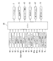
- the injector 2 the intake throttle valve 33, the variable nozzle vane mechanism 43, the exhaust throttle valve 53, the high pressure EGR valve 62, and the low pressure EGR valve 72 are electrically connected to the ECU (Electronic Control Unit) 10. ing.
- ECU Electronic Control Unit
- the ECU 10 includes an A / F sensor 80, an air flow meter 81, an intake air temperature sensor 82, a supercharging pressure sensor 83, a plurality of exhaust gas temperature sensors 84a to 84d, a water temperature sensor 85, a crank position sensor 86, an accelerator opening sensor 87, an intake air throttle. It is electrically connected to various sensors such as a valve opening sensor 88, an LPL differential pressure sensor 89a, a DPF differential pressure sensor 89b, a compressor outlet temperature sensor 8A, a high pressure EGR valve opening sensor 8H, and a low pressure EGR valve opening sensor 8L. Yes.
- the A / F sensor 80 is a sensor that detects the oxygen concentration in the exhaust gas upstream of the oxidation catalyst 51 and downstream of the turbine 42, and outputs a detection signal that continuously changes in accordance with the oxygen concentration.
- the air flow meter 81 is a sensor that measures the amount of air (fresh air amount) that flows into the intake passage 3 from the atmosphere.
- the intake air temperature sensor 82 is a sensor that detects the temperature of the air flowing through the intake passage 3 (specifically, the temperature downstream of the intercooler 32 and upstream of the intake throttle valve 33).
- the supercharging pressure sensor 83 is a sensor that detects the pressure on the downstream side of the intake throttle valve 33 (the pressure of the intake air supercharged by the turbocharger 4).
- the exhaust temperature sensors 84a to 84d are arranged upstream of the oxidation catalyst 51, downstream of the oxidation catalyst 51, downstream of the particulate filter 52, and downstream of the low pressure EGR cooler 73 in the low pressure EGR passage 71 (low pressure EGR valve 72).
- the exhaust gas temperature at each location is detected.
- the water temperature sensor 85 is a sensor that detects the temperature of the cooling water circulating inside the engine 1.
- the crank position sensor 86 is a sensor that detects the rotational position of the crankshaft of the engine 1.
- the accelerator opening sensor 87 is a sensor that detects an operation amount (accelerator opening) of the accelerator pedal by the driver.
- the intake throttle valve opening sensor 88 is a sensor that detects the opening of the intake throttle valve 33.
- the LPL differential pressure sensor 89 a is a sensor that measures the differential pressure between the upstream pressure and the downstream pressure of the low pressure EGR cooler 73 in the LPL-EGR mechanism 7.
- the DPF differential pressure sensor 89b is a sensor that measures the differential pressure between the upstream pressure and the downstream pressure of the particulate filter 52, and estimates the amount of PM (Particulate Matter) accumulation in the particulate filter 52.
- Used for The compressor outlet temperature sensor 8A is a sensor that detects the temperature of the intake air flowing out of the compressor 41 (the mixture of supercharged fresh air and low-pressure EGR gas).
- the high pressure EGR valve opening sensor 8H is a sensor that detects the opening of the high pressure EGR valve 62.
- the low pressure EGR valve opening sensor 8L is a sensor that detects the opening of the low pressure EGR valve 72.
- the ECU 10 controls the injector 2, the intake throttle valve 33, the variable nozzle vane mechanism 43, the exhaust throttle valve 53, the high-pressure EGR valve 62, and the like based on the detected values and measured values of the various sensors 80 to 89a, 89b, 8A, 8H, and 8L.
- the low pressure EGR valve 72 is controlled.
- the ECU 10 controls the HPL-EGR mechanism 6 and the LPL-EGR mechanism 7 in accordance with the operating state (engine load or the like) of the engine 1.
- the EGR mechanisms 6 and 7 to be used are selected according to the map of FIG. That is, when the engine 1 is in the low load operation state, the ECU 10 recirculates the exhaust gas using the HPL-EGR mechanism 6 (recirculation operation in the high pressure EGR region). When the engine 1 is in a high load operation state, the ECU 10 recirculates the exhaust gas by the LPL-EGR mechanism 7 (reflux operation in the low pressure EGR region).
- the ECU 10 When the engine 1 is in the medium load operation state, the ECU 10 performs exhaust gas recirculation by using both the HPL-EGR mechanism 6 and the LPL-EGR mechanism 7 (reflux operation in the MPL region). These specific controls will be described later.
- 3 is an operation region where both the high pressure EGR valve 62 of the HPL-EGR mechanism 6 and the low pressure EGR valve 72 of the LPL-EGR mechanism 7 are closed, that is, an operation region where EGR gas is not recirculated. It is. This is an operation region where the amount of smoke in the exhaust gas increases or the system reliability such as EGR gas temperature restriction is required.
- the usage mode of the HPL-EGR mechanism 6 and the LPL-EGR mechanism 7 is switched according to the operating state of the engine 1, or when the EGR mechanisms 6 and 7 are used together, Therefore, an appropriate amount of EGR gas can be recirculated in a proper operation region, and the NOx concentration in the exhaust gas can be suitably reduced.
- the ECU 10 uses the HPL-EGR mechanism 6 to recirculate the exhaust gas in the operation region other than the region X, as shown in the map of FIG. I do. This is because the HPL-EGR mechanism 6 that does not include an EGR cooler is utilized to recirculate the exhaust gas having a relatively high temperature, thereby prematurely warming up the engine 1 and activating the oxidation catalyst 51 early. Because.
- control of the EGR gas amount in the HPL-EGR mechanism 6 and the control of the EGR gas amount in the LPL-EGR mechanism 7 will be described.
- the control of the EGR gas amount in the HPL-EGR mechanism 6 and the control of the EGR gas amount in the LPL-EGR mechanism 7 are independent controls.
- the target EGR gas recirculation amount (hereinafter referred to as “target high-pressure EGR gas return”).
- the flow rate ”) and the estimated EGR gas recirculation amount (hereinafter referred to as“ estimated high pressure EGR gas recirculation amount ”), and the high pressure EGR gas recirculation amount approaches the target high pressure EGR gas recirculation amount.
- the opening degree of the EGR valve 62 and the opening degree of the intake throttle valve 33 are feedback controlled (hereinafter referred to as “EGR feedback control”).
- the target high-pressure EGR gas recirculation amount in this case is set according to the operating state of the engine 1 (particularly the engine load).
- the estimated high pressure EGR gas recirculation amount is detected by the opening of the high pressure EGR valve 62 detected by the high pressure EGR valve opening sensor 8H, the temperature of the intake air detected by the intake air temperature sensor 82, and the supercharging pressure sensor 83. It is obtained from a predetermined arithmetic expression or map stored in advance in a ROM (Read Only Memory) of the ECU 10 with the differential pressure between the intake pressure and the pressure in the exhaust manifold as a parameter.
- the pressure in the exhaust manifold is obtained from a predetermined arithmetic expression or map stored in advance in the ROM of the ECU 10 with the intake pressure, the operating state amount of the engine 1 and the like as parameters.
- the target EGR gas recirculation amount (hereinafter referred to as “target low pressure EGR”).
- Gas recirculation amount) and the estimated EGR gas recirculation amount (hereinafter referred to as “estimated low pressure EGR gas recirculation amount"), and the estimated low pressure EGR gas recirculation amount approaches the target low pressure EGR gas recirculation amount.
- the opening degree of the low pressure EGR valve 72 and the opening degree of the exhaust throttle valve 53 are feedback controlled (EGR feedback control).
- the target low-pressure EGR gas recirculation amount in this case is set according to the operating state of the engine 1 (particularly the engine load).
- the estimated low-pressure EGR gas recirculation amount is the opening of the low-pressure EGR valve 72 detected by the low-pressure EGR valve opening sensor 8L, the exhaust temperature detected by the exhaust temperature sensors 84a to 84d, and the LPL differential pressure sensor. Using the differential pressure between the upstream side pressure and the downstream side pressure of the low pressure EGR cooler 73 detected by 89a as a parameter, it is obtained from a predetermined arithmetic expression or map stored in the ROM of the ECU 10 in advance.
- the EGR feedback control in the HPL region is performed so that the intake air amount detected by the air flow meter 81 matches the target intake air amount set according to the engine load, the engine speed (engine speed), and the like.
- a target high-pressure EGR gas recirculation amount is set, and as described above, the opening degree of the high-pressure EGR valve 62 is feedback-controlled so that the estimated high-pressure EGR gas recirculation amount matches the target high-pressure EGR gas recirculation amount.
- the low pressure EGR valve 72 is maintained fully closed.
- the intake air amount obtained by the air flow meter 81 is smaller than the target value and the actual EGR rate is higher than the target EGR rate (EGR rate determined according to the operating state of the engine 1 or the like)
- the opening degree of the high pressure EGR valve 62 is increased so as to increase the amount of EGR gas. If the estimated high pressure EGR gas recirculation amount does not reach the target high pressure EGR gas recirculation amount even if the opening amount of the high pressure EGR valve 62 is increased in this way, the opening amount of the intake throttle valve 33 is decreased ( The amount of EGR gas recirculated through the high pressure EGR passage 61 is increased by decreasing the pressure on the downstream side of the intake throttle valve 33. This brings the actual EGR rate closer to the target EGR rate.
- a control mode in which the EGR gas is recirculated using only the HPL-EGR mechanism 6 is referred to as an HPL mode.
- the target value of the intake air amount and the target value of the EGR gas amount may each have a certain range to be a target range.
- the opening degree of the high pressure EGR valve 62 may be adjusted so that the EGR gas amount becomes a target value or a target range.
- the target low-pressure EGR gas return is performed so that the intake air amount detected by the air flow meter 81 matches the target intake air amount set in accordance with the engine load, the engine speed, and the like.
- the flow rate is set, and as described above, the opening degree of the low pressure EGR valve 72 is feedback-controlled so that the estimated low pressure EGR gas recirculation amount matches the target low pressure EGR gas recirculation amount.
- the high pressure EGR valve 62 is kept fully closed (unless the amount of EGR gas is insufficient).
- the opening degree of the low pressure EGR valve 72 is reduced so as to reduce the amount of EGR gas.
- the opening degree of the low pressure EGR valve 72 is increased so as to increase the amount of EGR gas.
- the opening amount of the low pressure EGR valve 72 is increased in this way, the opening amount of the high pressure EGR valve 62 is increased, Alternatively, the opening amount of the exhaust throttle valve 53 is decreased (the degree of closeness is increased), and the amount of EGR gas recirculated through the low pressure EGR passage 71 is increased. This brings the actual EGR rate closer to the target EGR rate.
- a control mode in which the EGR gas is recirculated using only the LPL-EGR mechanism 7 is referred to as an LPL mode.
- the target value of the intake air amount and the target value of the EGR gas amount may each have a certain range to be a target range.
- the opening degree of the low pressure EGR valve 72 may be adjusted so that the EGR gas amount becomes a target value or a target range.
- the opening degree of the high pressure EGR valve 62 is controlled so that the estimated high pressure EGR gas recirculation amount reaches the target high pressure EGR gas recirculation amount.
- the opening degree control for the high pressure EGR valve 62 is the same as that in the low load operation described above.
- the opening degree of the low pressure EGR valve 72 is controlled so that the estimated low pressure EGR gas recirculation amount reaches the target low pressure EGR gas recirculation amount.
- the opening degree control for the low-pressure EGR valve 72 is the same as in the above-described high-load operation.
- a control mode for supplying EGR gas using both the HPL-EGR mechanism 6 and the LPL-EGR mechanism 7 is referred to as an MPL mode.
- the target value of the intake air amount and the target value of the EGR gas amount may each have a certain range to be a target range.
- the opening degree of one of the low pressure EGR valve 72 and the high pressure EGR valve 62 may be adjusted so that the EGR gas amount becomes a target value or a target range.
- engine oil is contained in the EGR gas flowing through the low pressure EGR passage 71 of the LPL-EGR mechanism 7, that is, the EGR gas recirculated upstream of the compressor 41. May be included.
- the temperature of the intake air (mixture of fresh air and high-temperature EGR gas) flowing into the compressor 41 is relatively high. Therefore, when the EGR gas is supercharged together with the intake air in the compressor 41, deposits are generated due to the oil contained in the EGR gas being exposed to a high temperature, and the blades of the compressor wheel and the inner surface of the turbo housing The deposit may adhere to the (wall surface of the compressor passage).
- the supercharging efficiency of the turbocharger 4 is lowered, the engine output is lowered, and the acceleration performance of the vehicle is lowered. Further, the NOx amount in the exhaust gas may increase due to a decrease in the amount of EGR gas accompanying a decrease in the supercharging efficiency of the turbocharger 4.
- the deposit is more likely to be generated in a low temperature environment as the engine oil is more deteriorated (the degree of deterioration is higher). For this reason, as the deterioration of the engine oil progresses, the temperature at which deposits are generated (the temperature of the intake air accompanying the supercharging and the temperature of the compressor wheel) becomes lower. Further, the temperature of the intake air accompanying supercharging increases as the supercharging pressure of the turbocharger 4 increases. That is, the temperature of the supercharged intake air is correlated with the supercharging pressure of the turbocharger 4.
- the turbocharger 4's supercharging pressure is adjusted appropriately, and the intake air temperature (correlation with the compressor wheel temperature) accompanying supercharging is a deposit corresponding to the current deterioration level of engine oil. If the temperature is lower than the generated temperature, the generation of deposit can be avoided, and if the intake air temperature is less than the generated temperature, it is possible to arbitrarily set the turbocharger 4 supercharging pressure. is there.
- the supercharging pressure of the turbocharger 4 can be adjusted by controlling the opening of the variable nozzle vane provided in the variable nozzle vane mechanism 43 as described above.
- the degree of deterioration of the oil is recognized from the soot concentration in the oil.
- an allowable upper limit value of the intake air temperature (actually the outlet temperature of the compressor 41) is obtained from the degree of deterioration of the oil, and the allowable supercharging pressure of the turbocharger 4 is calculated based on the allowable upper limit value.
- the supercharging pressure of the turbocharger 4 is set within the range of the allowable supercharging pressure. For this reason, even if the supercharging pressure of the turbocharger 4 is increased to the maximum pressure within the allowable supercharging pressure range, the deposit does not occur.
- the EGR valve control when the supercharging pressure of the turbocharger 4 is changed, for example, when the supercharging pressure is limited by the allowable supercharging pressure, the EGR rate changes as the intake air amount varies. Therefore, the opening of the EGR valve (high pressure EGR when the EGR gas is recirculated by the HPL-EGR mechanism 6 so that the EGR rate does not change, that is, the target EGR rate is obtained).
- the opening degree of the valve 62, and the opening degree of the low pressure EGR valve 72 when the EGR gas is recirculated by the LPL-EGR mechanism 7 are controlled.
- the target EGR rate is obtained from an EGR map described later according to the engine speed, the engine load, and the like.
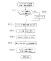
- FIG. 5 is a flowchart showing an outline of procedures of supercharging pressure control and EGR valve control.
- FIG. 6 is a flowchart showing a procedure for extracting the compressor outlet temperature allowable upper limit value.
- FIG. 7 is a diagram showing an allowable upper limit temperature map for obtaining the compressor outlet temperature allowable upper limit value from the suit concentration in the oil.
- FIG. 8 is a flowchart showing a procedure of turbocharger supercharging pressure control.
- FIG. 9 is a flowchart showing a procedure of EGR valve control.
- step ST1 the degree of deterioration of the engine oil is calculated, and the allowable upper limit value of the compressor outlet temperature is extracted based on the degree of deterioration. Details will be described later with reference to the flowchart of FIG.
- step ST2 the process proceeds to step ST2, and within the allowable range in which the occurrence of the deposit can be avoided based on the extracted upper limit value of the compressor outlet temperature and other information (information such as the operating state of the engine 1).
- the control supercharging pressure is obtained, and the supercharging pressure control of the turbocharger 4 is performed so that this control supercharging pressure is obtained. Details will be described later using the flowchart of FIG.
- step ST3 it is determined whether or not the EGR rate varies due to the effect of the supercharging pressure control of the turbocharger 4, and the EGR rate does not vary. If the target boost pressure can be controlled within the allowable range, a NO determination is made in step ST3.
- step ST4 the EGR valve corresponding to the new air amount is used in accordance with the basic operation of the MPL-EGR system described above. Control of 62, 72, etc. (control of intake throttle valve 33 and exhaust throttle valve 53 as required) is performed.
- the supercharging pressure control of the turbocharger 4 in step ST2 is performed, the EGR rate varies, that is, when the target supercharging pressure is limited by the allowable range, In step ST3, a YES determination is made.
- step ST5 control of the EGR valves 62, 72 and the like according to the EGR rate (the EGR rate that changes due to the supercharging pressure control) (if necessary, the intake throttle valve 33 and The control of the exhaust throttle valve 53 is performed. That is, the opening degree control of the EGR valves 62, 72, etc. is performed so that the target EGR rate is achieved. Details will be described later with reference to the flowchart of FIG.
- FIG. 6 is a detailed operation procedure of step ST1 in the flowchart of FIG. 5 described above.
- step ST11 it is determined whether or not there is information for resetting the integrated amount of soot in the oil accumulated during operation of the engine 1.
- the engine oil present in the oil pan of the engine 1 contains almost no suit, and is integrated in past routines.
- the suit amount (suit integrated amount; Sootn) that has been set is reset.
- this information is set so that the operator who has changed the oil can input reset information to the ECU 10 or can automatically recognize the replacement of the engine oil.
- the ECU 10 The reset instruction signal is input to the above.
- step ST11 If there is reset information on the suit integrated amount (reset information is input) and YES is determined in step ST11, the process proceeds to step ST12, the suit integrated amount Sootn is set (reset) to “0”, and the process proceeds to step ST13. Move.
- step ST11 if there is no reset information of the suit integrated amount and NO is determined in step ST11, the suit integrated amount up to that point is stored (while being stored in the backup RAM (Random Access Memory) of the ECU 10), step ST13. Move on.
- step ST13 the operation state quantity of the engine 1 is read.
- the engine load calculated from the engine speed calculated based on the output from the crank position sensor 86, the operation amount of the accelerator pedal detected by the accelerator opening sensor 87, various temperature sensors 82, 84a to 84d,
- the operation state quantity such as the temperature detection signal output from 85 and 8A is read.
- step ST14 based on the operating state amount of the engine 1 read in step ST13, the suit amount Soot generated in the engine oil in this routine is calculated.
- the calculation of the suit amount Soot is performed by using an arithmetic expression or a map (calculation expression set in advance based on experiments, simulations, etc., and stored in the ROM of the ECU 10). Or according to the map).
- Step ST15 the suit amount Soot calculated in the current routine is added to the currently accumulated suit integrated amount Sootn, and the new suit is obtained.
- the accumulated amount is stored as “Sotn” (Sotn ⁇ Sotn + Sot). As a result, the suit amount in the total oil is currently calculated.
- step ST16 the suit concentration in the total oil amount is calculated. That is, the suit concentration is calculated by dividing the suit integrated amount Sootn calculated in step ST15 by the total oil amount stored in advance (for example, the total amount of oil injected at the previous oil change).
- step ST17 the allowable upper limit value of the compressor outlet temperature is extracted from the allowable upper limit temperature map shown in FIG.
- This allowable upper limit temperature map is a map for determining the allowable upper limit value of the compressor outlet temperature so that oil deposits do not occur in the compressor 41. Experiments, simulations and the like are performed in advance for each type of the engine 1. And is stored in the ROM of the ECU 10. As shown in this allowable upper limit temperature map, the higher the suit concentration in the oil, the lower the compressor outlet temperature allowable upper limit value.
- the temperature at which deposits are generated decreases as the suit concentration in the oil increases and the deterioration of the oil proceeds (the degree of deterioration increases).
- the upper limit value of the compressor outlet temperature (the allowable upper limit value of the compressor outlet temperature) at which no deposit is generated for the current suit concentration is extracted. For example, if the suit concentration in the oil is A in the figure, the allowable upper limit value of the compressor outlet temperature is obtained as TA. In this case, if the compressor outlet temperature is equal to or lower than TA, the deposit in the compressor 41 is It will not occur.
- the allowable upper limit temperature map is created assuming engine oil that is most likely to be deposited (for example, specific mineral oil) among engine oils that may be introduced. As a result, if the temperature is kept below the compressor outlet temperature allowable upper limit value obtained from this allowable upper limit temperature map, the occurrence of deposits can be reliably avoided.
- the allowable upper limit temperature map is stored in the backup RAM of the ECU 10 so as to be rewritable, and the operator who has changed the oil rewrites the allowable upper limit temperature map corresponding to the type of engine oil that has been added. You may do it.
- FIG. 8 shows the details of the operation procedure of step ST2 in the flowchart of FIG. 5 described above.
- step ST21 various information such as the operating state and environmental state of the engine 1 and the compressor outlet temperature allowable upper limit value extracted by the operation of FIG. 6 are read.
- the various information such as the operating state and the environmental state of the engine 1 are detected by, for example, the intake air temperature upstream of the compressor 41 estimated from the intake air temperature detected by the intake air temperature sensor 82, and the compressor outlet temperature sensor 8A. Examples include the intake air temperature at the compressor outlet, the intake air amount detected by the air flow meter 81, and the EGR gas recirculation amount estimated by the above-described estimation operation of the EGR gas recirculation amount.
- the sum of the intake air amount detected by the air flow meter 81 and the estimated low-pressure EGR gas recirculation amount among the EGR gas recirculation amount estimated by the EGR gas recirculation amount estimation operation is obtained as the gas amount passing through the compressor 41. Will be.
- the intake air temperature upstream of the compressor 41 may be directly detected by providing an intake air temperature sensor upstream of the compressor 41.
- an allowable upper limit supercharging pressure is calculated.
- This allowable upper limit supercharging pressure is a supercharging pressure at which the intake air temperature at the compressor outlet matches the allowable upper limit value of the compressor outlet temperature, and even if the supercharging pressure of the turbocharger 4 is increased to the allowable upper limit supercharging pressure.
- the value is such that the occurrence of deposits can be suppressed if the degree of deterioration of the oil is present. For this reason, this allowable upper limit supercharging pressure is also obtained as a lower value as the suit concentration in the oil becomes higher and the deterioration of the oil progresses (the deterioration degree becomes higher).
- an arithmetic expression or map for obtaining an allowable upper limit supercharging pressure from the compressor outlet temperature allowable upper limit value is stored in the ROM of the ECU 10, and the allowable upper limit supercharging pressure is obtained from this arithmetic expression or map.
- step ST23 it is determined whether the target boost pressure exceeds the allowable upper limit boost pressure (target boost pressure> allowable upper limit boost pressure). judge.
- This target boost pressure is a parameter such as an engine load calculated from the engine speed calculated based on the output from the crank position sensor 86, an accelerator pedal operation amount detected by the accelerator opening sensor 87, and the like.
- As a calculation formula or map (calculation formula or map (target boost pressure map) set in advance based on experiments, simulations, etc. and stored in the ECU 10) for calculating the target boost pressure.
- the control boost pressure the boost pressure that is the actual control target
- FIG. 9 shows details of the operation procedure of step ST5 in the flowchart of FIG. 5 described above.
- step ST31 various information such as the operating state and environmental state of the engine 1 is read.
- the engine speed calculated based on the output from the crank position sensor 86, the fuel injection amount from the injector 2, the coolant temperature detected by the water temperature sensor 85, and the intake air temperature detected by the intake air temperature sensor 82
- the operation state quantity such as the atmospheric pressure detected by the atmospheric pressure sensor (not shown) and the environmental state quantity are read.
- a target EGR rate is calculated.
- This target EGR rate is determined according to the operating state of the engine 1 and the like. Specifically, an EGR map that determines the EGR amount (EGR rate) using the engine speed and the engine load as parameters is stored in the ROM of the ECU 10 and calculated based on the detection value of the crank position sensor 86. The target EGR rate is obtained by fitting an engine load obtained from the engine speed and the accelerator pedal operation amount detected by the accelerator opening sensor 87 to the EGR map.
- step ST33 when the supercharging pressure is controlled in accordance with the control supercharging pressure, the opening degree of the EGR valve is controlled so that the actual EGR rate matches the target EGR rate.
- the control supercharging pressure is limited by the allowable upper limit supercharging pressure during high load operation (when YES is determined in step ST23)
- the EGR rate decreases as the supercharging pressure decreases.
- the actual EGR rate is lower than the target EGR rate, and the estimated low-pressure EGR gas recirculation amount is smaller than the target low-pressure EGR gas recirculation amount.
- the opening of the low pressure EGR valve 72 is increased so as to increase the EGR gas amount. If the estimated low pressure EGR gas recirculation amount does not reach the target low pressure EGR gas recirculation amount even if the opening amount of the low pressure EGR valve 72 is increased in this way, the opening amount of the high pressure EGR valve 62 is increased, Alternatively, the opening amount of the exhaust throttle valve 53 is decreased (the degree of closeness is increased), and the amount of EGR gas recirculated through the low pressure EGR passage 71 is increased. Thereby, the actual EGR rate can be brought close to the target EGR rate, and the amount of NOx generation can be reduced.
- the EGR rate may decrease as the boost pressure decreases. Since the actual EGR rate is lower than the target EGR rate, the amount of EGR gas is increased according to the EGR distribution rate, as in the case of the above-described operation (basic operation during medium load operation of the MPL-EGR system). Thus, the opening degree of the low pressure EGR valve 72 and the opening degree of the high pressure EGR valve 62 are controlled. If the actual EGR rate does not reach the target EGR rate even if the opening degree of each of the EGR valves 62 and 72 is controlled in this way, the opening degree of the intake throttle valve 33 or the exhaust throttle valve 53 is controlled. To increase the amount of EGR gas. Thereby, the actual EGR rate can be brought close to the target EGR rate, and the amount of NOx generation can be reduced.
- the above-mentioned allowable upper limit temperature map can be used to increase the supercharging pressure to the maximum while suppressing the generation of deposits. Is possible.
- the present invention is applied to the engine 1 including the two EGR mechanisms 6 and 7 .
- the present invention is not limited to this, and can also be applied to an engine having one EGR mechanism (LPL-EGR mechanism) or an engine having three or more EGR mechanisms.
- the intake air temperature flowing out from the compressor 41 is detected by the compressor outlet temperature sensor 8A.
- the present invention is not limited to this, and the intake air temperature flowing out from the compressor 41 may be estimated based on the intake air temperature flowing into the compressor 41. Further, instead of detecting or estimating the compressor outlet temperature, the temperature of the compressor 41 itself (a component of the compressor 41; for example, a blade of a compressor wheel) may be detected or estimated.
- the degree of deterioration of the engine oil is determined based on the suit concentration.
- the present invention is not limited to this, and the degree of engine oil deterioration (degree of deterioration due to oil oxidation) may be determined based on the elapsed time after oil replacement. Further, other methods may be used as a method for determining the degree of engine oil deterioration. For example, deterioration determination based on the electrical resistance value of oil as disclosed in JP 2011-196220 A, deterioration determination based on oil transmittance as disclosed in JP 2011-7084 A, etc. Is mentioned.
- the cause of the deposit is the engine oil contained in the EGR gas.
- the engine oil contained in the blow-by gas may be used.
- the present invention is applicable to control of a diesel engine equipped with a turbocharger and an LPL-EGR mechanism.
Landscapes
- Engineering & Computer Science (AREA)
- Chemical & Material Sciences (AREA)
- Mechanical Engineering (AREA)
- General Engineering & Computer Science (AREA)
- Combustion & Propulsion (AREA)
- Physics & Mathematics (AREA)
- Fluid Mechanics (AREA)
- Analytical Chemistry (AREA)
- Exhaust-Gas Circulating Devices (AREA)
- Output Control And Ontrol Of Special Type Engine (AREA)
- Supercharger (AREA)
Abstract
Le degré de détérioration d'huile est obtenu à partir de la concentration de suie dans l'huile de moteur, et la valeur de limite supérieure admissible pour la température de sortie de compresseur est obtenue à partir de ce degré de détérioration d'huile (étape ST1). La pression de suralimentation limite supérieure admissible correspondant à cette valeur de limite supérieure pour la température de sortie de compresseur est calculée. Une pression de suralimentation cible, qui peut être déterminée à partir de l'état de fonctionnement du moteur, est comparée à la pression de suralimentation limite supérieure admissible, et lorsque la pression de suralimentation cible est inférieure ou égale à la pression de suralimentation limite supérieure admissible, le turbocompresseur est contrôlé avec cette pression de suralimentation cible en tant que pression de suralimentation de commande. Lorsque la pression de suralimentation cible dépasse la pression de suralimentation limite supérieure admissible le turbocompresseur est commandé avec la pression de suralimentation limite supérieure admissible en tant que pression de suralimentation de commande, et la soupape de recirculation des gaz d'échappement est commandée de façon à empêcher le débit de recirculation des gaz d'échappement de diverger du débit de recirculation des gaz d'échappement cible (étape ST5).
Priority Applications (3)
| Application Number | Priority Date | Filing Date | Title |
|---|---|---|---|
| EP12868493.3A EP2816208B1 (fr) | 2012-02-14 | 2012-02-14 | Dispositif de commande pour moteur à combustion interne |
| PCT/JP2012/053360 WO2013121517A1 (fr) | 2012-02-14 | 2012-02-14 | Dispositif de commande pour moteur à combustion interne |
| JP2013558609A JP5935813B2 (ja) | 2012-02-14 | 2012-02-14 | 内燃機関の制御装置 |
Applications Claiming Priority (1)
| Application Number | Priority Date | Filing Date | Title |
|---|---|---|---|
| PCT/JP2012/053360 WO2013121517A1 (fr) | 2012-02-14 | 2012-02-14 | Dispositif de commande pour moteur à combustion interne |
Publications (1)
| Publication Number | Publication Date |
|---|---|
| WO2013121517A1 true WO2013121517A1 (fr) | 2013-08-22 |
Family
ID=48983681
Family Applications (1)
| Application Number | Title | Priority Date | Filing Date |
|---|---|---|---|
| PCT/JP2012/053360 Ceased WO2013121517A1 (fr) | 2012-02-14 | 2012-02-14 | Dispositif de commande pour moteur à combustion interne |
Country Status (3)
| Country | Link |
|---|---|
| EP (1) | EP2816208B1 (fr) |
| JP (1) | JP5935813B2 (fr) |
| WO (1) | WO2013121517A1 (fr) |
Cited By (7)
| Publication number | Priority date | Publication date | Assignee | Title |
|---|---|---|---|---|
| CN104514592A (zh) * | 2013-09-30 | 2015-04-15 | Fpt工业股份公司 | 防止内燃发动机本身低效润滑引起发动机机械损坏的系统 |
| JP2015108326A (ja) * | 2013-12-04 | 2015-06-11 | マツダ株式会社 | 排気ガス還流制御装置 |
| JP2015121160A (ja) * | 2013-12-24 | 2015-07-02 | トヨタ自動車株式会社 | 機関システムの制御装置 |
| JP2015129488A (ja) * | 2014-01-08 | 2015-07-16 | 本田技研工業株式会社 | 内燃機関の制御装置 |
| JP2022097171A (ja) * | 2020-12-18 | 2022-06-30 | トヨタ自動車株式会社 | ターボチャージャのオイルコーキング堆積量の推定装置 |
| US20240011429A1 (en) * | 2022-07-11 | 2024-01-11 | Toyota Jidosha Kabushiki Kaisha | Control device for internal combustion engine |
| CN119801755A (zh) * | 2025-02-14 | 2025-04-11 | 东风汽车集团股份有限公司 | 一种目标egr率的优化控制方法 |
Families Citing this family (1)
| Publication number | Priority date | Publication date | Assignee | Title |
|---|---|---|---|---|
| DE102023113312B3 (de) * | 2023-05-22 | 2024-10-17 | Volkswagen Aktiengesellschaft | Verdichterschutzfunktion zur Einhaltung der Verdichteraustrittstemperatur, Steuervorrichtung, Verbrennungskraftmaschine und Fahrzeug |
Citations (10)
| Publication number | Priority date | Publication date | Assignee | Title |
|---|---|---|---|---|
| JPS61162541U (fr) * | 1985-03-29 | 1986-10-08 | ||
| JPH1019788A (ja) * | 1996-07-03 | 1998-01-23 | Nippon Soken Inc | 潤滑油中のスーツの測定システム |
| JP2006299827A (ja) * | 2005-04-15 | 2006-11-02 | Toyota Industries Corp | ターボチャージャの制御装置 |
| JP2007211595A (ja) * | 2006-02-07 | 2007-08-23 | Toyota Motor Corp | 内燃機関の排気還流装置 |
| JP2010096029A (ja) | 2008-10-14 | 2010-04-30 | Toyota Motor Corp | 内燃機関のブローバイガス処理装置 |
| JP2011007084A (ja) | 2009-06-24 | 2011-01-13 | Nippon Soken Inc | 内燃機関の制御装置 |
| JP2011089470A (ja) | 2009-10-22 | 2011-05-06 | Toyota Motor Corp | Egrシステムの故障診断装置 |
| JP2011127561A (ja) | 2009-12-21 | 2011-06-30 | Toyota Motor Corp | 内燃機関の排気浄化装置 |
| JP2011196220A (ja) | 2010-03-18 | 2011-10-06 | Toyota Motor Corp | オイル異常診断装置 |
| JP2012007544A (ja) | 2010-06-25 | 2012-01-12 | Toyota Motor Corp | 可変容量型過給機の制御装置 |
Family Cites Families (1)
| Publication number | Priority date | Publication date | Assignee | Title |
|---|---|---|---|---|
| JP5075137B2 (ja) * | 2009-01-21 | 2012-11-14 | 本田技研工業株式会社 | 内燃機関のegr制御装置 |
-
2012
- 2012-02-14 JP JP2013558609A patent/JP5935813B2/ja not_active Expired - Fee Related
- 2012-02-14 WO PCT/JP2012/053360 patent/WO2013121517A1/fr not_active Ceased
- 2012-02-14 EP EP12868493.3A patent/EP2816208B1/fr not_active Not-in-force
Patent Citations (10)
| Publication number | Priority date | Publication date | Assignee | Title |
|---|---|---|---|---|
| JPS61162541U (fr) * | 1985-03-29 | 1986-10-08 | ||
| JPH1019788A (ja) * | 1996-07-03 | 1998-01-23 | Nippon Soken Inc | 潤滑油中のスーツの測定システム |
| JP2006299827A (ja) * | 2005-04-15 | 2006-11-02 | Toyota Industries Corp | ターボチャージャの制御装置 |
| JP2007211595A (ja) * | 2006-02-07 | 2007-08-23 | Toyota Motor Corp | 内燃機関の排気還流装置 |
| JP2010096029A (ja) | 2008-10-14 | 2010-04-30 | Toyota Motor Corp | 内燃機関のブローバイガス処理装置 |
| JP2011007084A (ja) | 2009-06-24 | 2011-01-13 | Nippon Soken Inc | 内燃機関の制御装置 |
| JP2011089470A (ja) | 2009-10-22 | 2011-05-06 | Toyota Motor Corp | Egrシステムの故障診断装置 |
| JP2011127561A (ja) | 2009-12-21 | 2011-06-30 | Toyota Motor Corp | 内燃機関の排気浄化装置 |
| JP2011196220A (ja) | 2010-03-18 | 2011-10-06 | Toyota Motor Corp | オイル異常診断装置 |
| JP2012007544A (ja) | 2010-06-25 | 2012-01-12 | Toyota Motor Corp | 可変容量型過給機の制御装置 |
Non-Patent Citations (1)
| Title |
|---|
| See also references of EP2816208A4 * |
Cited By (8)
| Publication number | Priority date | Publication date | Assignee | Title |
|---|---|---|---|---|
| CN104514592A (zh) * | 2013-09-30 | 2015-04-15 | Fpt工业股份公司 | 防止内燃发动机本身低效润滑引起发动机机械损坏的系统 |
| JP2015108326A (ja) * | 2013-12-04 | 2015-06-11 | マツダ株式会社 | 排気ガス還流制御装置 |
| JP2015121160A (ja) * | 2013-12-24 | 2015-07-02 | トヨタ自動車株式会社 | 機関システムの制御装置 |
| JP2015129488A (ja) * | 2014-01-08 | 2015-07-16 | 本田技研工業株式会社 | 内燃機関の制御装置 |
| JP2022097171A (ja) * | 2020-12-18 | 2022-06-30 | トヨタ自動車株式会社 | ターボチャージャのオイルコーキング堆積量の推定装置 |
| JP7388343B2 (ja) | 2020-12-18 | 2023-11-29 | トヨタ自動車株式会社 | ターボチャージャのオイルコーキング堆積量の推定装置 |
| US20240011429A1 (en) * | 2022-07-11 | 2024-01-11 | Toyota Jidosha Kabushiki Kaisha | Control device for internal combustion engine |
| CN119801755A (zh) * | 2025-02-14 | 2025-04-11 | 东风汽车集团股份有限公司 | 一种目标egr率的优化控制方法 |
Also Published As
| Publication number | Publication date |
|---|---|
| EP2816208A1 (fr) | 2014-12-24 |
| JP5935813B2 (ja) | 2016-06-15 |
| EP2816208B1 (fr) | 2018-11-21 |
| JPWO2013121517A1 (ja) | 2015-05-11 |
| EP2816208A4 (fr) | 2015-01-14 |
Similar Documents
| Publication | Publication Date | Title |
|---|---|---|
| JP5935813B2 (ja) | 内燃機関の制御装置 | |
| JP5327393B1 (ja) | Egrシステムの異常診断装置 | |
| JP5301857B2 (ja) | コモンレール式電子噴射制御系エンジン | |
| US8919107B2 (en) | Control device of diesel engine with turbocharger | |
| CN102959208B (zh) | 内燃机的控制装置 | |
| JP2010255462A (ja) | 内燃機関 | |
| US7168408B2 (en) | Control device of internal combustion engine | |
| JP2009281144A (ja) | 過給機付き内燃機関の制御装置 | |
| JP5803622B2 (ja) | Egrシステムの異常診断装置 | |
| JP4415739B2 (ja) | エンジン排気微粒子の捕集量検出装置 | |
| JP5621638B2 (ja) | 内燃機関の排気再循環システム | |
| JP2013213473A (ja) | 温度推定装置及び温度センサ故障診断装置 | |
| CN109989839B (zh) | 用于对置活塞发动机的egr系统和方法 | |
| JP2017115647A (ja) | 吸気温度制御装置 | |
| JP6328519B2 (ja) | ブローバイガス還元装置と過給機を備えたエンジンの排気還流装置 | |
| JP7700745B2 (ja) | 内燃機関の制御装置 | |
| JP2014015913A (ja) | 内燃機関のガス温度推定装置 | |
| JP5262992B2 (ja) | 内燃機関の制御装置 | |
| JP2012163060A (ja) | 内燃機関の排気再循環システム | |
| JP2011127437A (ja) | 内燃機関の制御装置 | |
| JP7130952B2 (ja) | 内燃機関の制御装置 | |
| JP5556302B2 (ja) | エンジンの制御方法及び制御装置 | |
| JP2016061152A (ja) | エンジンの排気還流制御装置 |
Legal Events
| Date | Code | Title | Description |
|---|---|---|---|
| 121 | Ep: the epo has been informed by wipo that ep was designated in this application |
Ref document number: 12868493 Country of ref document: EP Kind code of ref document: A1 |
|
| ENP | Entry into the national phase |
Ref document number: 2013558609 Country of ref document: JP Kind code of ref document: A |
|
| NENP | Non-entry into the national phase |
Ref country code: DE |
|
| WWE | Wipo information: entry into national phase |
Ref document number: 2012868493 Country of ref document: EP |