WO2013121527A1 - Dispositif d'entraînement pour véhicule hybride - Google Patents
Dispositif d'entraînement pour véhicule hybride Download PDFInfo
- Publication number
- WO2013121527A1 WO2013121527A1 PCT/JP2012/053394 JP2012053394W WO2013121527A1 WO 2013121527 A1 WO2013121527 A1 WO 2013121527A1 JP 2012053394 W JP2012053394 W JP 2012053394W WO 2013121527 A1 WO2013121527 A1 WO 2013121527A1
- Authority
- WO
- WIPO (PCT)
- Prior art keywords
- planetary gear
- gear mechanism
- carrier
- gear
- rotating electrical
- Prior art date
- Legal status (The legal status is an assumption and is not a legal conclusion. Google has not performed a legal analysis and makes no representation as to the accuracy of the status listed.)
- Ceased
Links
Images






Classifications
-
- B—PERFORMING OPERATIONS; TRANSPORTING
- B60—VEHICLES IN GENERAL
- B60K—ARRANGEMENT OR MOUNTING OF PROPULSION UNITS OR OF TRANSMISSIONS IN VEHICLES; ARRANGEMENT OR MOUNTING OF PLURAL DIVERSE PRIME-MOVERS IN VEHICLES; AUXILIARY DRIVES FOR VEHICLES; INSTRUMENTATION OR DASHBOARDS FOR VEHICLES; ARRANGEMENTS IN CONNECTION WITH COOLING, AIR INTAKE, GAS EXHAUST OR FUEL SUPPLY OF PROPULSION UNITS IN VEHICLES
- B60K6/00—Arrangement or mounting of plural diverse prime-movers for mutual or common propulsion, e.g. hybrid propulsion systems comprising electric motors and internal combustion engines
- B60K6/20—Arrangement or mounting of plural diverse prime-movers for mutual or common propulsion, e.g. hybrid propulsion systems comprising electric motors and internal combustion engines the prime-movers consisting of electric motors and internal combustion engines, e.g. HEVs
- B60K6/22—Arrangement or mounting of plural diverse prime-movers for mutual or common propulsion, e.g. hybrid propulsion systems comprising electric motors and internal combustion engines the prime-movers consisting of electric motors and internal combustion engines, e.g. HEVs characterised by apparatus, components or means specially adapted for HEVs
- B60K6/36—Arrangement or mounting of plural diverse prime-movers for mutual or common propulsion, e.g. hybrid propulsion systems comprising electric motors and internal combustion engines the prime-movers consisting of electric motors and internal combustion engines, e.g. HEVs characterised by apparatus, components or means specially adapted for HEVs characterised by the transmission gearings
- B60K6/365—Arrangement or mounting of plural diverse prime-movers for mutual or common propulsion, e.g. hybrid propulsion systems comprising electric motors and internal combustion engines the prime-movers consisting of electric motors and internal combustion engines, e.g. HEVs characterised by apparatus, components or means specially adapted for HEVs characterised by the transmission gearings with the gears having orbital motion
-
- B—PERFORMING OPERATIONS; TRANSPORTING
- B60—VEHICLES IN GENERAL
- B60K—ARRANGEMENT OR MOUNTING OF PROPULSION UNITS OR OF TRANSMISSIONS IN VEHICLES; ARRANGEMENT OR MOUNTING OF PLURAL DIVERSE PRIME-MOVERS IN VEHICLES; AUXILIARY DRIVES FOR VEHICLES; INSTRUMENTATION OR DASHBOARDS FOR VEHICLES; ARRANGEMENTS IN CONNECTION WITH COOLING, AIR INTAKE, GAS EXHAUST OR FUEL SUPPLY OF PROPULSION UNITS IN VEHICLES
- B60K6/00—Arrangement or mounting of plural diverse prime-movers for mutual or common propulsion, e.g. hybrid propulsion systems comprising electric motors and internal combustion engines
- B60K6/20—Arrangement or mounting of plural diverse prime-movers for mutual or common propulsion, e.g. hybrid propulsion systems comprising electric motors and internal combustion engines the prime-movers consisting of electric motors and internal combustion engines, e.g. HEVs
- B60K6/22—Arrangement or mounting of plural diverse prime-movers for mutual or common propulsion, e.g. hybrid propulsion systems comprising electric motors and internal combustion engines the prime-movers consisting of electric motors and internal combustion engines, e.g. HEVs characterised by apparatus, components or means specially adapted for HEVs
- B60K6/38—Arrangement or mounting of plural diverse prime-movers for mutual or common propulsion, e.g. hybrid propulsion systems comprising electric motors and internal combustion engines the prime-movers consisting of electric motors and internal combustion engines, e.g. HEVs characterised by apparatus, components or means specially adapted for HEVs characterised by the driveline clutches
- B60K6/387—Actuated clutches, i.e. clutches engaged or disengaged by electric, hydraulic or mechanical actuating means
-
- B—PERFORMING OPERATIONS; TRANSPORTING
- B60—VEHICLES IN GENERAL
- B60K—ARRANGEMENT OR MOUNTING OF PROPULSION UNITS OR OF TRANSMISSIONS IN VEHICLES; ARRANGEMENT OR MOUNTING OF PLURAL DIVERSE PRIME-MOVERS IN VEHICLES; AUXILIARY DRIVES FOR VEHICLES; INSTRUMENTATION OR DASHBOARDS FOR VEHICLES; ARRANGEMENTS IN CONNECTION WITH COOLING, AIR INTAKE, GAS EXHAUST OR FUEL SUPPLY OF PROPULSION UNITS IN VEHICLES
- B60K6/00—Arrangement or mounting of plural diverse prime-movers for mutual or common propulsion, e.g. hybrid propulsion systems comprising electric motors and internal combustion engines
- B60K6/20—Arrangement or mounting of plural diverse prime-movers for mutual or common propulsion, e.g. hybrid propulsion systems comprising electric motors and internal combustion engines the prime-movers consisting of electric motors and internal combustion engines, e.g. HEVs
- B60K6/42—Arrangement or mounting of plural diverse prime-movers for mutual or common propulsion, e.g. hybrid propulsion systems comprising electric motors and internal combustion engines the prime-movers consisting of electric motors and internal combustion engines, e.g. HEVs characterised by the architecture of the hybrid electric vehicle
- B60K6/44—Series-parallel type
- B60K6/445—Differential gearing distribution type
-
- B—PERFORMING OPERATIONS; TRANSPORTING
- B60—VEHICLES IN GENERAL
- B60K—ARRANGEMENT OR MOUNTING OF PROPULSION UNITS OR OF TRANSMISSIONS IN VEHICLES; ARRANGEMENT OR MOUNTING OF PLURAL DIVERSE PRIME-MOVERS IN VEHICLES; AUXILIARY DRIVES FOR VEHICLES; INSTRUMENTATION OR DASHBOARDS FOR VEHICLES; ARRANGEMENTS IN CONNECTION WITH COOLING, AIR INTAKE, GAS EXHAUST OR FUEL SUPPLY OF PROPULSION UNITS IN VEHICLES
- B60K6/00—Arrangement or mounting of plural diverse prime-movers for mutual or common propulsion, e.g. hybrid propulsion systems comprising electric motors and internal combustion engines
- B60K6/20—Arrangement or mounting of plural diverse prime-movers for mutual or common propulsion, e.g. hybrid propulsion systems comprising electric motors and internal combustion engines the prime-movers consisting of electric motors and internal combustion engines, e.g. HEVs
- B60K6/22—Arrangement or mounting of plural diverse prime-movers for mutual or common propulsion, e.g. hybrid propulsion systems comprising electric motors and internal combustion engines the prime-movers consisting of electric motors and internal combustion engines, e.g. HEVs characterised by apparatus, components or means specially adapted for HEVs
- B60K6/38—Arrangement or mounting of plural diverse prime-movers for mutual or common propulsion, e.g. hybrid propulsion systems comprising electric motors and internal combustion engines the prime-movers consisting of electric motors and internal combustion engines, e.g. HEVs characterised by apparatus, components or means specially adapted for HEVs characterised by the driveline clutches
- B60K2006/381—Arrangement or mounting of plural diverse prime-movers for mutual or common propulsion, e.g. hybrid propulsion systems comprising electric motors and internal combustion engines the prime-movers consisting of electric motors and internal combustion engines, e.g. HEVs characterised by apparatus, components or means specially adapted for HEVs characterised by the driveline clutches characterized by driveline brakes
-
- F—MECHANICAL ENGINEERING; LIGHTING; HEATING; WEAPONS; BLASTING
- F16—ENGINEERING ELEMENTS AND UNITS; GENERAL MEASURES FOR PRODUCING AND MAINTAINING EFFECTIVE FUNCTIONING OF MACHINES OR INSTALLATIONS; THERMAL INSULATION IN GENERAL
- F16H—GEARING
- F16H37/00—Combinations of mechanical gearings, not provided for in groups F16H1/00 - F16H35/00
- F16H37/02—Combinations of mechanical gearings, not provided for in groups F16H1/00 - F16H35/00 comprising essentially only toothed or friction gearings
- F16H37/06—Combinations of mechanical gearings, not provided for in groups F16H1/00 - F16H35/00 comprising essentially only toothed or friction gearings with a plurality of driving or driven shafts; with arrangements for dividing torque between two or more intermediate shafts
- F16H37/08—Combinations of mechanical gearings, not provided for in groups F16H1/00 - F16H35/00 comprising essentially only toothed or friction gearings with a plurality of driving or driven shafts; with arrangements for dividing torque between two or more intermediate shafts with differential gearing
- F16H37/10—Combinations of mechanical gearings, not provided for in groups F16H1/00 - F16H35/00 comprising essentially only toothed or friction gearings with a plurality of driving or driven shafts; with arrangements for dividing torque between two or more intermediate shafts with differential gearing at both ends of intermediate shafts
- F16H2037/102—Combinations of mechanical gearings, not provided for in groups F16H1/00 - F16H35/00 comprising essentially only toothed or friction gearings with a plurality of driving or driven shafts; with arrangements for dividing torque between two or more intermediate shafts with differential gearing at both ends of intermediate shafts the input or output shaft of the transmission is connected or connectable to two or more differentials
-
- F—MECHANICAL ENGINEERING; LIGHTING; HEATING; WEAPONS; BLASTING
- F16—ENGINEERING ELEMENTS AND UNITS; GENERAL MEASURES FOR PRODUCING AND MAINTAINING EFFECTIVE FUNCTIONING OF MACHINES OR INSTALLATIONS; THERMAL INSULATION IN GENERAL
- F16H—GEARING
- F16H2200/00—Transmissions for multiple ratios
- F16H2200/20—Transmissions using gears with orbital motion
- F16H2200/2002—Transmissions using gears with orbital motion characterised by the number of sets of orbital gears
- F16H2200/2007—Transmissions using gears with orbital motion characterised by the number of sets of orbital gears with two sets of orbital gears
-
- Y—GENERAL TAGGING OF NEW TECHNOLOGICAL DEVELOPMENTS; GENERAL TAGGING OF CROSS-SECTIONAL TECHNOLOGIES SPANNING OVER SEVERAL SECTIONS OF THE IPC; TECHNICAL SUBJECTS COVERED BY FORMER USPC CROSS-REFERENCE ART COLLECTIONS [XRACs] AND DIGESTS
- Y02—TECHNOLOGIES OR APPLICATIONS FOR MITIGATION OR ADAPTATION AGAINST CLIMATE CHANGE
- Y02T—CLIMATE CHANGE MITIGATION TECHNOLOGIES RELATED TO TRANSPORTATION
- Y02T10/00—Road transport of goods or passengers
- Y02T10/60—Other road transportation technologies with climate change mitigation effect
- Y02T10/62—Hybrid vehicles
Definitions
- the present invention relates to a hybrid vehicle drive device.
- Patent Document 1 is provided with a mode switching mechanism that changes the positional relationship among a prime mover, a first motor / generator, a second motor / generator, an output element, and a reaction force element on the nomograph.
- a hybrid drive technology is disclosed.
- a hybrid vehicle drive device having a plurality of travel modes can be simplified.
- a plurality of EV driving modes and a plurality of HV driving modes can be realized by a hybrid vehicle drive device having a simple configuration.
- An object of the present invention is to provide a hybrid vehicle drive device capable of realizing a plurality of travel modes with a simple configuration.
- a drive device for a hybrid vehicle of the present invention includes a first planetary gear mechanism, a second planetary gear mechanism, a clutch, and a brake, and the first sun gear that is a sun gear of the first planetary gear mechanism is a first rotating electrical machine.
- the first ring gear which is the ring gear of the first planetary gear mechanism, is the engine
- the first carrier which is the carrier of the first planetary gear mechanism
- the first rotating element of the second planetary gear mechanism is connected to the second rotating electrical machine
- the third rotating element is connected to the engine and the first ring gear via the clutch.
- the rotating element is a sun gear of the second planetary gear mechanism, and the brake regulates the rotation of the third rotating element.
- the arrangement order of the rotation elements of the first planetary gear mechanism and the second planetary gear mechanism when the clutch is engaged is the first sun gear, The first rotating element, the first carrier and the second rotating element, the first ring gear and the third rotating element in this order, or the first rotating element, the first sun gear, the first carrier and the first It is preferable that the order is the two-rotating element, the first ring gear, and the third rotating element.
- the clutch and the brake are preferably meshing engagement devices.
- the hybrid vehicle drive device further includes a one-way clutch that restricts the rotation of the third rotation element.
- the second planetary gear mechanism is a single pinion type
- the second rotating element is a carrier of the second planetary gear mechanism
- the third rotating element is of the second planetary gear mechanism.
- a ring gear is preferred.
- the second planetary gear mechanism is a double pinion type
- the second rotating element is a ring gear of the second planetary gear mechanism
- the third rotating element is the second planetary gear mechanism. It is preferable that the carrier.
- the hybrid vehicle drive device includes a first planetary gear mechanism, a second planetary gear mechanism, a clutch, and a brake.
- the first sun gear that is the sun gear of the first planetary gear mechanism is in the first rotating electrical machine
- the first ring gear that is the ring gear of the first planetary gear mechanism is in the engine
- the first carrier that is the carrier of the first planetary gear mechanism is
- the second planetary gear mechanism is connected to the second rotating element and the drive wheel, respectively.
- the first rotating element of the second planetary gear mechanism is connected to the second rotating electric machine
- the third rotating element is connected to the engine and the first ring gear via a clutch.
- the first rotating element is a sun gear of the second planetary gear mechanism.
- the brake regulates the rotation of the third rotating element.
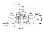
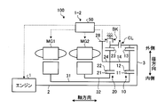
- FIG. 1 is a main part skeleton diagram of a vehicle according to an embodiment.
- FIG. 2 is a diagram illustrating an engagement table of the hybrid vehicle drive device according to the embodiment.
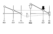
- FIG. 3 is a collinear diagram related to the EV-1 mode.
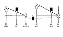
- FIG. 4 is a collinear diagram related to the EV-2 mode.
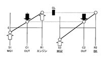
- FIG. 5 is a collinear diagram related to the HV-1 mode.
- FIG. 6 is a collinear diagram related to the HV-2 mode.
- FIG. 7 is a collinear diagram in the four-element mode.
- FIG. 8 is an explanatory diagram of the theoretical transmission efficiency of the hybrid vehicle drive device according to the embodiment.
- FIG. 9 is a main part skeleton diagram of a vehicle according to a first modification of the embodiment.
- FIG. 9 is a main part skeleton diagram of a vehicle according to a first modification of the embodiment.
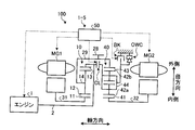
- FIG. 10 is a main part skeleton diagram of a vehicle according to a second modification of the embodiment.
- FIG. 11 is a main part skeleton diagram of a vehicle according to a third modification of the embodiment.
- FIG. 12 is a main part skeleton diagram of the vehicle according to the fourth modification example of the embodiment.
- FIG. 1 is a main part skeleton diagram of a vehicle 100 according to an embodiment of the present invention
- FIG. 2 is a diagram showing an engagement table of a hybrid vehicle drive device 1-1 according to the embodiment.
- the hybrid vehicle drive device 1-1 is a hybrid system having two planetary gears, two motors, and a plurality of engagement devices.
- the electric torque converter mode and the four-element planetary are shared. It has a composite split mode coupled in the order of MG1-MG2-output-engine on the diagram.
- the hybrid vehicle drive device 1-1 has one brake and one clutch as an engagement device, and these engagement / non-engagement results in two or more modes during hybrid operation and the number of drive MGs during EV operation. Two different modes can be realized. Further, the hybrid vehicle drive device 1-1 has two mechanical points on the low gear side, so that high transmission efficiency can be desired.
- a vehicle 100 shown in FIG. 1 includes an engine 1, a first planetary gear mechanism 10, a second planetary gear mechanism 20, a first rotating electrical machine MG1, a second rotating electrical machine MG2, a clutch CL, a brake BK, and an ECU 50. Yes.
- the hybrid vehicle drive device 1-1 according to the present embodiment includes the first planetary gear mechanism 10, the second planetary gear mechanism 20, the clutch CL, and the brake BK.
- the hybrid vehicle drive device 1-1 may further include an ECU 50.
- the engine 1 which is an example of the engine converts the combustion energy of the fuel into a rotary motion of the rotary shaft and outputs it.
- the rotating shaft of the engine 1 is connected to the input shaft 2.
- the input shaft 2 is an input shaft of the first planetary gear mechanism 10 and is arranged coaxially with the rotation shaft of the engine 1.
- the torque of the engine 1 is input to the first planetary gear mechanism 10 via the input shaft 2.
- the first planetary gear mechanism 10 is an example of a first differential mechanism.
- the first planetary gear mechanism 10 is a single pinion type and includes a first sun gear 11, a first pinion gear 12, a first ring gear 13, and a first carrier 14.
- the first ring gear 13 is coaxial with the first sun gear 11 and is disposed on the radially outer side of the first sun gear 11.
- the first pinion gear 12 is disposed between the first sun gear 11 and the first ring gear 13 and meshes with the first sun gear 11 and the first ring gear 13, respectively.
- the first pinion gear 12 is rotatably supported by the first carrier 14.
- the rotating shaft 31 of the first rotating electrical machine MG1 is coaxial with the input shaft 2 and is disposed on the radially outer side of the input shaft 2.
- the first sun gear 11 is connected to the rotating shaft 31. That is, the first sun gear 11 is rotatably supported coaxially with the input shaft 2 and is connected to the first rotating electrical machine MG1.
- the first ring gear 13 is connected to the input shaft 2 and rotates integrally with the input shaft 2. That is, the first ring gear 13 is connected to the engine 1 and can rotate integrally with the engine 1.
- the first carrier 14 is connected to the second carrier 24 via the cylindrical member 27.
- the cylindrical member 27 has a cylindrical shape and is disposed on the radially outer side of the first planetary gear mechanism 10 and the second planetary gear mechanism 20.
- the second planetary gear mechanism 20 is an example of a second differential mechanism.
- the second planetary gear mechanism 20 is a single pinion type and includes a second sun gear 21, a second pinion gear 22, a second ring gear 23, and a second carrier 24.
- the second sun gear 21 corresponds to the first rotating element
- the second carrier 24 corresponds to the second rotating element
- the second ring gear 23 corresponds to the third rotating element.
- the second ring gear 23 is coaxial with the second sun gear 21 and is disposed on the radially outer side of the second sun gear 21.
- the second pinion gear 22 is disposed between the second sun gear 21 and the second ring gear 23 and meshes with the second sun gear 21 and the second ring gear 23, respectively.
- the second pinion gear 22 is rotatably supported by the second carrier 24.
- the rotary shaft 25 of the second ring gear 23 is coaxial with the input shaft 2 and is disposed on an extension line of the input shaft 2.
- the rotating shaft 25 is rotatably supported.
- the second sun gear 21 is connected to the rotating shaft 32 of the second rotating electrical machine MG2.
- the rotating shaft 32 of the second rotating electrical machine MG2 is disposed coaxially with the rotating shaft 25 of the second ring gear 23 and on the radially outer side of the rotating shaft 25.
- the first carrier 14, the second carrier 24, and the cylindrical member 27 are rotatably supported on the same axis as the input shaft 2.
- the first pinion gear 12 can rotate (revolve) around the central axis of the input shaft 2 together with the first carrier 14, and is supported by the first carrier 14 to rotate (rotate) around the central axis of the first pinion gear 12. It is possible.
- the second pinion gear 22 can rotate (revolve) around the central axis of the rotation shaft 25 together with the second carrier 24, and is supported by the second carrier 24 to rotate around the central axis of the second pinion gear 22 (rotation). It is possible.
- a counter drive gear 28 is disposed on the outer peripheral surface of the cylindrical member 27.
- the counter drive gear 28 is connected to drive wheels via a gear mechanism including a differential device and a speed reduction mechanism and a drive shaft.
- the counter drive gear 28 is an output gear disposed on the output shafts of the planetary gear mechanisms 10 and 20, and outputs torque output from the first planetary gear mechanism 10 and the second planetary gear mechanism 20 to the drive wheels.
- the first carrier 14 and the second carrier 24 are connected to drive wheels via a counter drive gear 28, a gear mechanism, and a drive shaft.
- the clutch CL is a clutch device that can connect the input shaft 2 and the rotary shaft 25.
- the second ring gear 23 is connected to the engine 1 and the first ring gear 13 via the clutch CL.
- the clutch CL can be, for example, a friction engagement type clutch, but is not limited thereto, and a known clutch device such as a meshing type clutch may be used as the clutch CL.
- a meshed dog clutch or the like is used as the clutch CL, drag loss in the opened state is suppressed.
- the clutch CL is driven or engaged or released by an actuator that is operated by, for example, hydraulic pressure or electromagnetic force. When an electromagnetic actuator is used, a hydraulic circuit is not necessary, and the transaxle can be simplified and reduced in weight.
- the fully engaged clutch CL can connect the input shaft 2 and the rotary shaft 25 and rotate the input shaft 2 and the rotary shaft 25 integrally. That is, the fully engaged clutch CL restricts relative rotation of the engine 1, the first ring gear 13, and the second ring gear 23.
- the opened clutch CL disconnects the input shaft 2 and the rotary shaft 25 and allows relative rotation between the input shaft 2 and the rotary shaft 25. That is, the opened clutch CL allows relative rotation of the engine 1, the first ring gear 13, and the second ring gear 23.
- the clutch CL can be controlled to be in a semi-engaged state.
- the brake BK is a brake device that can regulate the rotation of the second ring gear 23 by engaging it.
- the brake BK has an engagement element disposed on the disk member 26 and an engagement element connected to the vehicle body side, for example, a case that houses the rotating electrical machines MG1, MG2, the planetary gear mechanisms 10, 20, and the like.
- the disk member 26 is a disk-shaped member that protrudes radially outward from the rotation shaft 25 of the second ring gear 23.
- the brake BK may be a friction engagement type clutch device similar to the clutch CL, but is not limited thereto, and a known clutch device such as a dog clutch, for example, a dog clutch may be used as the brake BK. .
- the brake BK is driven or engaged or released by an actuator that is operated by, for example, hydraulic pressure or electromagnetic force.
- the fully engaged brake BK connects the second ring gear 23 and the vehicle body side and can regulate the rotation of the second ring gear 23.
- the released brake BK disconnects the second ring gear 23 from the vehicle body side and allows the second ring gear 23 to rotate. Note that the brake BK can be controlled to a half-engaged state.
- the first rotating electrical machine MG1, the first planetary gear mechanism 10, the counter drive gear 28 and the clutch CL, the second planetary gear mechanism 20, and the second rotation are arranged on the same axis as the rotation axis of the engine 1 in order from the side closer to the engine 1.
- An electric machine MG2 and a brake BK are arranged.
- the first rotating electrical machine MG1 and the second rotating electrical machine MG2 each have a function as a motor (electric motor) and a function as a generator.
- the first rotating electrical machine MG1 and the second rotating electrical machine MG2 are connected to a battery via an inverter.
- the first rotating electrical machine MG1 and the second rotating electrical machine MG2 can convert the electric power supplied from the battery into mechanical power and output it, and are driven by the input power to convert the mechanical power into electric power. Can be converted.
- the electric power generated by the rotating electrical machines MG1 and MG2 can be stored in the battery.
- an AC synchronous motor generator can be used as the first rotating electrical machine MG1 and the second rotating electrical machine MG2.
- the ECU 50 causes the first rotating electrical machine MG1 to function mainly as a rotating electrical machine that takes the reaction force of the engine 1, and causes the second rotating electrical machine MG2 to function mainly as a rotating electrical machine for driving.
- the present invention is not limited to this, and the first rotating electrical machine MG1 may be made to mainly function as a rotating electrical machine for driving and the second rotating electrical machine MG2 may be made to function mainly as a rotating electrical machine for receiving reaction force.
- the vehicle 100 includes an ECU 50.
- the ECU 50 is an electronic control unit having a computer.
- the ECU 50 has a function as a control device that controls each part of the vehicle 100.
- the ECU 50 is connected to the engine 1, the first rotating electrical machine MG1, the second rotating electrical machine MG2, the clutch CL, and the brake BK, and the engine 50, the first rotating electrical machine MG1, the second rotating electrical machine MG2, the clutch CL, and the brake BK. Can be controlled.
- the ECU 50 can control the torque and rotation speed of the engine 1 by fuel injection control, ignition control, electronic throttle control, and the like of the engine 1. Further, the ECU 50 can control the rotation speed and torque of the first rotating electrical machine MG1 and the second rotating electrical machine MG2. Further, the ECU 50 can control the engagement / release state of the clutch CL and the brake BK by controlling the hydraulic pressure supplied to the clutch CL and the brake BK from a hydraulic control device (not shown).
- the ECU 50 has a vehicle speed, an accelerator opening, a rotational speed of the first rotating electrical machine MG1 (hereinafter also simply referred to as “MG1 rotational speed”), and a rotational speed of the second rotating electrical machine MG2 (hereinafter simply referred to as “MG2 rotational speed”). And a sensor for detecting the output shaft speed, the state of the battery, and the like. ECU 50 calculates a required output for vehicle 100 based on information acquired from each sensor, and can control engine 1, rotating electrical machines MG1, MG2, clutch CL, brake BK, and the like.
- FIG. 2 is a view showing an operation engagement table of the hybrid vehicle drive device 1-1 according to the present embodiment.
- the ⁇ marks in the brake BK column and the clutch CL column indicate engagement, and the blank column indicates disengagement.
- the vehicle 100 can selectively execute hybrid (HV) traveling or EV traveling.
- the HV travel is a travel mode in which the vehicle 100 travels using the engine 1 as a power source.
- HV traveling in addition to the engine 1, at least one of the first rotating electrical machine MG1 and the second rotating electrical machine MG2 can be used as a power source.
- EV traveling is a traveling mode in which traveling is performed using at least one of the first rotating electrical machine MG1 and the second rotating electrical machine MG2 as a power source. In EV traveling, it is possible to travel with the engine 1 stopped.
- the hybrid vehicle drive device 1-1 according to the present embodiment has an EV-1 mode and an EV-2 mode as EV travel modes.
- the EV-1 mode is a single motor EV mode in which the vehicle 100 travels using the second rotating electrical machine MG2 as a single power source.
- the EV-2 mode is a dual motor EV mode in which the vehicle 100 can travel using the first rotating electrical machine MG1 and the second rotating electrical machine MG2 as power sources.
- FIG. 3 is a collinear diagram related to the EV-1 mode.
- symbols S1, C1, and R1 indicate the first sun gear 11, the first carrier 14, and the first ring gear 13, respectively.
- Reference numerals S2, C2, and R2 denote the second sun gear 21, the second carrier 24, and the second ring gear 23, respectively.
- the ECU 50 engages the brake BK and releases the clutch CL.
- the rotation of the second ring gear 23 is restricted. Further, since the clutch CL is in the released state, the engine 1, the first ring gear 13, and the second ring gear 23 can be rotated relative to each other.
- the first carrier 14 that is the output element of the first planetary gear mechanism 10 and the second carrier 24 that is the output element of the second planetary gear mechanism 20 are connected to each other and rotate at the same rotational speed.
- the ECU 50 causes the vehicle 100 to travel using the second rotating electrical machine MG2 as a power source.
- the second ring gear 23 whose rotation is restricted functions as a reaction force receiver for the torque of the second rotating electrical machine MG2 (hereinafter also simply referred to as “MG2 torque”), and outputs the MG2 torque from the second carrier 24.
- MG2 torque the torque of the second rotating electrical machine MG2
- the second planetary gear mechanism 20 decelerates the rotation of the second rotating electrical machine MG2 and outputs it from the second carrier 24. That is, the second planetary gear mechanism 20 can amplify and output the MG2 torque.
- the brake BK regulates the rotation of the second ring gear 23
- the reduction ratio at which the second planetary gear mechanism 20 decelerates the rotation of the second rotating electrical machine MG2 is relatively large.
- the degree of deceleration when the second sun gear 21 is fixed is The smallest degree of deceleration when the second ring gear 23 is fixed is the largest. Therefore, in the hybrid vehicle driving device 1-1 according to the present embodiment, the amplification factor of the MG2 torque can be increased, and the shortage of the starting driving force during EV traveling can be suppressed.
- an increase in the size of the second rotating electrical machine MG2 for securing the starting driving force is suppressed.
- the second rotating electrical machine MG2 can be operated at a thermally advantageous operating point.
- the second rotating electrical machine MG2 can output a positive torque from the second carrier 24 by generating a positive torque by outputting a positive torque, thereby generating a driving force in the forward direction in the vehicle 100. Further, the second rotating electrical machine MG2 can output negative torque from the second carrier 24 by outputting negative torque and rotating negatively, and can cause the vehicle 100 to generate a backward driving force.
- the positive rotation is the rotation direction of the first carrier 14 and the second carrier 24 when the vehicle 100 moves forward, and the positive torque indicates the torque in the positive rotation direction.
- the first ring gear 13 connected to the engine 1 stops rotating, and the first sun gear 11 idles.
- regenerative power generation can be performed by the second rotating electrical machine MG2 to generate a braking force.
- FIG. 4 is a collinear diagram related to the EV-2 mode.
- the ECU 50 engages the brake BK and the clutch CL in the EV-2 mode.
- the clutch CL When the clutch CL is in the engaged state, the relative rotation of the engine 1, the first ring gear 13, and the second ring gear 23 is restricted. Further, when the brake BK is in the engaged state, the rotation of the second ring gear 23 is restricted. Accordingly, in the EV-2 mode, the rotation of the engine 1, the first ring gear 13 and the second ring gear 23 is restricted.
- the first ring gear 13 whose rotation is restricted functions as a reaction force receiver for the torque of the first rotating electrical machine MG1 (hereinafter also simply referred to as “MG1 torque”), and outputs the MG1 torque from the first carrier 14.
- the first rotating electrical machine MG1 can output a positive torque from the first carrier 14 by generating a positive torque by outputting a positive torque, thereby causing the vehicle 100 to generate a driving force in the forward direction. Further, the first rotating electrical machine MG1 can output negative torque from the first carrier 14 by outputting negative torque and rotating negatively, and can cause the vehicle 100 to generate a driving force in the reverse direction.
- the second ring gear 23 whose rotation is restricted functions as a reaction force receiver for the MG2 torque, and can output the MG2 torque from the second carrier 24.
- the second rotating electrical machine MG2 can output positive torque from the second carrier 24 by generating positive torque by outputting positive torque, and can generate a driving force in the forward direction in the vehicle 100. Further, the second rotating electrical machine MG2 can output negative torque from the second carrier 24 by outputting negative torque and rotating negatively, and can cause the vehicle 100 to generate a backward driving force.
- the vehicle 100 can travel by generating a travel driving force by at least one of the first rotating electrical machine MG1 and the second rotating electrical machine MG2.
- the first rotating electrical machine MG1 and the second rotating electrical machine MG2 are used as power sources, and the MG1 torque and MG2 torque are output from the counter drive gear 28 to the driving wheels, respectively, to drive the vehicle 100.
- the MG1 torque and MG2 torque are output from the counter drive gear 28 to the driving wheels, respectively, to drive the vehicle 100.
- at least one of the first rotating electrical machine MG1 and the second rotating electrical machine MG2 can be idled or regenerated.
- FIG. 5 is a collinear diagram related to the HV-1 mode.
- the ECU 50 engages the brake BK and releases the clutch CL. Since the brake BK is in the engaged state, the second ring gear 23 functions as a reaction force receiver for the MG2 torque and can output the MG2 torque from the second carrier 24.
- the ECU 50 can cause the first rotating electrical machine MG1 to output torque so that the first rotating electrical machine MG1 functions as a reaction force receiver for the torque of the engine 1 (hereinafter also simply referred to as “engine torque”).
- engine torque The first rotating electrical machine MG1 can output the positive torque output from the engine 1 from the first carrier 14 by outputting the positive torque.
- the first rotating electrical machine MG1 When the first rotating electrical machine MG1 outputs a positive torque and receives a reaction force in a negative rotation state, the first rotating electrical machine MG1 can generate a power and recover a part of the power of the engine 1 as electric power.
- the second rotating electrical machine MG2 can output an assist torque that assists the engine 1 by outputting a positive torque, or can perform regenerative power generation during deceleration.
- the rotation of the engine 1 can be decelerated and output from the first carrier 14 and the degree of deceleration can be controlled by controlling the first rotating electrical machine MG1. That is, the HV-1 mode is an electric torque converter mode capable of amplifying the engine torque by electrical control and outputting it from the first carrier 14 and controlling the amplification degree.
- FIG. 6 is a collinear diagram related to the HV-2 mode.
- the ECU 50 releases the brake BK and engages the clutch CL.
- the brake BK is in the released state
- the second ring gear 23 is allowed to rotate.
- the clutch CL is in the engaged state, the relative rotation between the first ring gear 13 and the second ring gear 23 is restricted, and both can rotate integrally.
- the first rotating electrical machine MG1 can output the engine torque from the first carrier 14 by receiving a reaction force of the engine torque by outputting a positive torque.
- the second rotating electrical machine MG ⁇ b> 2 receives the reaction force of the engine torque by outputting a positive torque, and can output the engine torque from the second carrier 24.
- the reaction force can be applied to the power output from the engine 1 by either the first rotating electrical machine MG1 or the second rotating electrical machine MG2.
- the reaction force of the engine 1 can be received by one or both of the first rotating electrical machine MG1 and the second rotating electrical machine MG2, and can be operated at an efficient operating point, or a restriction such as torque limitation due to heat. Can be relaxed. Therefore, high efficiency of the hybrid vehicle 100 can be achieved.
- the power of the engine 1 is divided into the output shaft and the first rotating electrical machine MG1 using the first planetary gear mechanism 10 as a power split planetary, or the output shaft using the second planetary gear mechanism 20 as a power split planetary. This is a composite split mode in which the power of the engine 1 can also be divided into the second rotating electrical machine MG2.
- the reaction force is preferentially received by the rotary electric machine that can operate efficiently among the first rotary electric machine MG1 and the second rotary electric machine MG2, the efficiency can be improved.
- the necessary reaction force can be satisfied by assisting with regeneration (or output) of the other rotating electrical machine.
- FIG. 7 is a collinear diagram for the 4-element mode, and is a collinear diagram for the EV-2 mode.
- the first ring gear 13 and the second ring gear 23 are coupled to form one rotating element.
- the first planetary gear mechanism 10 and the second planetary gear mechanism 20 include the first sun gear 11, the first carrier 14 and the second carrier 24, the first ring gear 13 and the second ring gear 23, and the second sun gear 21.
- the four rotating elements function as a four-element differential mechanism that rotates while being associated with each other.
- first sun gear 11 first rotating electrical machine MG1
- second sun gear 21 second Rotating electrical machine MG2
- first carrier 14 and second carrier 24 output
- first ring gear 13 engine 1
- second ring gear 23 second ring gear 23
- the first planetary gear mechanism 10 and the second planetary gear mechanism 20 may be configured so that the ring gears 23 are arranged in order.
- the second sun gear is larger than the distance between the axis (S1 axis) indicating the rotation speed of the first sun gear 11 and the axis (C1 axis) indicating the rotation speed of the first carrier 14 in the alignment chart of FIG.
- gear ratios of the planetary gear mechanisms 10 and 20 are determined so that the distance between the axis indicating the rotational speed of 21 (S2 axis) and the axis indicating the rotational speed of the second carrier 24 (C2 axis) is increased. Good.
- the first planetary gear mechanism 10 and the second planetary gear mechanism 20 are each a single pinion type. Accordingly, in the nomographic chart in the four-element mode, the position of the axis indicating the rotation speed of the first sun gear 11 (S1 axis) and the axis indicating the rotation speed of the second sun gear 21 (S2 axis) do not overlap. . This is because, in the collinear diagram of the single pinion type planetary gear mechanism, the position of the shaft indicating the rotation speed of the carrier is more than the center point between the axis indicating the rotation speed of the sun gear and the axis indicating the rotation speed of the ring gear. This is because it is located on the shaft side indicating the rotation speed of the gear.
- At least one of the first planetary gear mechanism 10 and the second planetary gear mechanism 20 is of a double pinion type or the like, so that the S1 axis indicating the rotation speed of the first sun gear 11 and the second sun gear 21 (third It is also possible to overlap the S2 axis indicating the rotation speed of the rotation element).
- the hybrid vehicle drive device 1-1 has two mechanical points in the HV-2 mode, thereby realizing a highly efficient hybrid system. be able to.
- the mechanical point is a mechanical transmission point and a high-efficiency operating point with zero electrical path.
- FIG. 8 is an explanatory diagram of the theoretical transmission efficiency of the hybrid vehicle drive device 1-1 according to this embodiment.
- the horizontal axis represents the transmission ratio
- the vertical axis represents the theoretical transmission efficiency.
- the transmission ratio is a ratio (reduction ratio) of the input side rotational speed to the output side rotational speed of the first planetary gear mechanism 10 and the second planetary gear mechanism 20, for example, the first carrier 14 and the second carrier 24.
- the ratio of the rotation speed of the first ring gear 13 to the rotation speed of On the horizontal axis the left side is the high gear side with a small gear ratio, and the right side is the low gear side with a large gear ratio.
- the theoretical transmission efficiency is 1 when the power input to the planetary gear mechanisms 10 and 20 is all transmitted to the counter drive gear 28 by mechanical transmission without passing through the electric path.
- the broken line 61 is a transmission efficiency line in the HV-1 mode
- the solid line 62 is a transmission efficiency line in the HV-2 mode.
- the transmission efficiency line 61 in the HV-1 mode has the maximum efficiency at the speed ratio ⁇ 1.
- the gear ratio ⁇ 1 is a gear ratio at which the rotation speed of the first rotating electrical machine MG1 (first sun gear 11) is zero. Therefore, at the speed ratio ⁇ 1, an electric path due to the reaction force of the first rotating electrical machine MG1 does not occur, and power can be transmitted from the engine 1 to the counter drive gear 28 only by mechanical power transmission.
- the speed ratio ⁇ 1 is also referred to as “first mechanical transmission speed ratio ⁇ 1”.
- the first machine transmission speed ratio ⁇ 1 is a speed ratio on the underdrive side, that is, a speed ratio larger than the constant speed.
- the transmission efficiency line 62 in the HV-2 mode indicates the transmission efficiency when a reaction force of the engine torque is appropriately received by at least one of the first rotating electrical machine MG1 and the second rotating electrical machine MG2.
- the torque may be shared between the first rotating electrical machine MG1 and the second rotating electrical machine MG2 so that power can be transmitted most efficiently with respect to the gear ratio.
- the transmission efficiency line 62 in the HV-2 mode has a mechanical point at the speed ratio ⁇ 2 in addition to the first mechanical transmission speed ratio ⁇ 1.
- the gear ratio ⁇ 2 is a gear ratio at which the rotation speed of the second rotating electrical machine MG2 (second ring gear 23) is zero. Therefore, at the speed ratio ⁇ 2, an electric path due to the reaction force of the second rotating electrical machine MG2 does not occur, and power can be transmitted from the engine 1 to the counter drive gear 28 only by mechanical power.
- the speed ratio ⁇ 2 is also referred to as “second mechanical transmission speed ratio ⁇ 2”.
- the second machine transmission speed ratio ⁇ 2 is a speed ratio on the low gear side with respect to the first machine transmission speed ratio ⁇ 1.
- the S2 axis indicating the rotation speed of the second sun gear 21 is C1 indicating the rotation speed of the carriers 14 and 24 relative to the S1 axis indicating the rotation speed of the first sun gear 11.
- the relative relationship between the first mechanical transmission speed ratio ⁇ 1 and the second mechanical transmission speed ratio ⁇ 2 is determined according to the gear ratio ⁇ 1 of the first planetary gear mechanism 10 and the gear ratio ⁇ 2 of the second planetary gear mechanism 20.
- the gear ratios ⁇ 1 and ⁇ 2 can be expressed by the following formulas (1) and (2), for example.
- ⁇ 1 number of teeth of first sun gear 11 / number of teeth of first ring gear 13
- ⁇ 2 number of teeth of second sun gear 21 / number of teeth of second ring gear 23 (2)
- the first machine transmission speed ratio ⁇ 1 and the second machine transmission speed ratio ⁇ 2 become closer to each other.
- the first machine transmission speed ratio ⁇ 1 and the second machine transmission speed ratio ⁇ 2 are separated from each other on the alignment chart shown in FIG. 7, the first machine transmission speed ratio ⁇ 1 and the second machine The difference from the transmission speed ratio ⁇ 2 increases.
- the hybrid vehicle drive device 1-1 includes the two HV modes including the HV-2 mode having two mechanical points in the low gear range, and the two rotating electric machines MG1 and MG2.
- Two EV modes including the EV-2 mode for driving can be realized.
- the two HV modes and the two EV modes can be realized with a simple configuration of the two planetary gear mechanisms 10, 20, one clutch CL, and one brake BK.
- the hybrid vehicle drive device 1-1 has two mechanical points on the low gear side with respect to the constant speed (gear ratio 1) in the HV-2 mode, and thus has a high transmission efficiency during low gear operation. Can be realized. Further, the interval between the first machine transmission speed ratio ⁇ 1 and the second machine transmission speed ratio ⁇ 2 tends to be relatively narrow. For example, in the second planetary gear mechanism 20, the first sun gear 21 is the first rotating element, the second carrier 24 is the second rotating element, and the second ring gear 23 is the third rotating element. The interval between the mechanical transmission speed ratio ⁇ 1 and the second mechanical transmission speed ratio ⁇ 2 is reduced. In other words, although the range of the gear ratio for achieving high efficiency is narrow, the gear train can output the driving force with low loss within the range.
- the reaction force of the engine 1 can be received by sharing the torque with one or both of the rotating electrical machines MG1 and MG2. Therefore, it becomes possible to operate the rotating electrical machines MG1 and MG2 at an efficient operating point, and to ease restrictions such as torque limitation due to heat.
- the hybrid vehicle drive device 1-1 has an EV-2 mode that can be driven by two rotating electric machines MG1 and MG2 as an EV travel mode. Therefore, it is possible to generate (or regenerate) the torque by sharing one or both of the rotating electrical machines MG1 and MG2. As a result, it becomes possible to operate the rotating electrical machines MG1 and MG2 at an efficient operating point, and to ease restrictions such as torque limitation due to heat.
- the first planetary gear mechanism 10 and the second planetary gear mechanism 20 are single pinion type planetary gear mechanisms, and therefore, the number of meshing of the gears is small, which is advantageous in terms of loss reduction. . Further, since the output shaft can be arranged at the outermost diameter, there is an advantage that it is easy to adapt to the multi-axis FF structure.
- the planetary gear mechanisms 10 and 20 have the highest rotational speed at the sun gears 11 and 21, it is advantageous in terms of strength such as centrifugal force.
- FIG. 9 is a main part skeleton diagram of a vehicle according to a first modification of the embodiment.
- the hybrid vehicle drive device 1-2 according to the present modification differs from the hybrid vehicle drive device 1-1 of the above embodiment in that electrical parts and mechanical parts are arranged together. .
- the first rotating electrical machine MG1, the second rotating electrical machine MG2, the counter drive gear 28, the second planetary gear mechanism 20 and the brake BK are sequentially arranged from the side closer to the engine 1.
- a clutch CL and a first planetary gear mechanism 10 are disposed.
- a disk member 3 is connected to the end of the input shaft 2 opposite to the engine side.
- the input shaft 2 is connected to the first ring gear 13 via the disk member 3.
- the rotating shaft 31 of the first rotating electrical machine MG1 is hollow and is disposed on the radially outer side of the input shaft 2.
- the rotating shaft 32 of the second rotating electrical machine MG2 is hollow and is disposed on the radially outer side of the rotating shaft 31 of the first rotating electrical machine MG1.
- the brake BK is disposed on the outer side in the radial direction of the second ring gear 23.
- the brake BK regulates the engagement of the rotation of the second ring gear 23.
- the clutch CL connects and disconnects the engine 1, the first ring gear 13, and the second ring gear 23.
- electrical system parts such as the rotating electrical machines MG1 and MG2 and mechanical system parts such as the planetary gear mechanisms 10 and 20, the clutch CL, and the brake BK are arranged together. be able to.
- electrical parts and mechanical parts can be assembled in different cases in different factories. Therefore, the space and weight of parts to be transported can be reduced.
- inspection and initial setting after each assembly can be performed separately at the component stage.
- FIG. 10 is a main part skeleton diagram of a vehicle according to a second modification of the embodiment.
- the hybrid vehicle drive device 1-3 according to this modification is different from the hybrid vehicle drive device 1-1 of the above embodiment in that a one-way clutch OWC is provided.
- the one-way clutch OWC makes it unnecessary to engage the brake BK when starting the EV mode.
- the one-way clutch OWC is arranged in parallel with the brake BK.
- the one-way clutch OWC regulates the rotation of the second ring gear 23.
- the one-way clutch OWC allows the second ring gear 23 to rotate in the positive direction and restricts the rotation in the negative direction.
- the one-way clutch OWC can be a sprag type, for example.
- the inner ring of the one-way clutch OWC is connected to the disc member 26, and the outer ring is connected to the vehicle body side. When the inner ring tries to rotate relative to the outer ring in the negative direction, the sprags mesh with each other to restrict the relative rotation between the inner ring and the outer ring.
- the one-way clutch OWC can function as a reaction force receiver for the MG2 torque in the EV-1 mode.
- a negative torque acts on the second ring gear 23 and the one-way clutch OWC is engaged.
- the one-way clutch OWC functions as a reaction force receiver for the MG2 torque, and can output the MG2 torque from the second carrier 24.
- the hybrid vehicle drive apparatus 1-3 According to the hybrid vehicle drive apparatus 1-3 according to this modification, it is not necessary to engage the brake BK when starting the EV-1 mode. Therefore, the oil pump operation in a stopped state or the like becomes unnecessary, and the control becomes simple and the energy required for driving the electric oil pump is reduced.
- FIG. 11 is a main part skeleton diagram of a vehicle according to a third modification of the embodiment.
- the hybrid vehicle drive apparatus 1-4 according to this modification is different from the hybrid vehicle drive apparatus 1-2 according to the first modification in that a one-way clutch OWC is provided.
- the one-way clutch OWC is arranged in parallel with the brake BK.
- the one-way clutch OWC regulates the rotation of the second ring gear 23.
- the one-way clutch OWC allows the second ring gear 23 to rotate in the positive direction and restricts the rotation in the negative direction.
- the one-way clutch OWC can be a sprag type, for example.
- the inner ring of the one-way clutch OWC is connected to the second ring gear 23, and the outer ring is connected to the vehicle body side. When the inner ring tries to rotate relative to the outer ring in the negative direction, the sprags mesh with each other to restrict the relative rotation between the inner ring and the outer ring.
- the one-way clutch OWC according to the present modification can achieve the same effects as the one-way clutch OWC according to the second modification.
- FIG. 12 is a main part skeleton diagram of the vehicle according to the fourth modification example of the embodiment.
- the hybrid vehicle drive device 1-5 according to this modification differs from the hybrid vehicle drive device 1-3 according to the second modification of the above embodiment in that the second planetary gear mechanism 40 is a double pinion type. It is a point.
- the first planetary gear mechanism 10 may be a double pinion type.
- the second planetary gear mechanism 40 includes a second sun gear 41, an inner second pinion gear 42a, an outer second pinion gear 42b, a second ring gear 43, and a second carrier 44.
- the second ring gear 43 is connected to the first carrier 14 via the cylindrical member 29.
- a counter drive gear 28 is disposed on the outer peripheral surface of the cylindrical member 29.
- the brake BK can regulate the rotation of the second carrier 44.
- the one-way clutch OWC allows positive rotation of the second carrier 44 and restricts negative rotation.
- the inner second pinion gear 42a meshes with the second sun gear 41 and the outer second pinion gear 42b, respectively.
- the outer second pinion gear 42b meshes with the inner second pinion gear 42a and the second ring gear 43, respectively.
- the inner second pinion gear 42 a and the outer second pinion gear 42 b are rotatably supported by the second carrier 44.
- the second carrier 44 is connected to the engine 1 and the first ring gear 13 via the clutch CL.
- the inner second pinion gear 42a and the outer second pinion gear 42b can rotate (revolve) around the central axis of the rotary shaft 32 together with the second carrier 44, and are supported by the second carrier 44 around the respective central axes. Can be rotated (rotated).
- the second sun gear 41 is connected to the rotary shaft 32 of the second rotary electric machine MG2. That is, in the second planetary gear mechanism 40 according to this modification, the second sun gear 41 corresponds to the first rotation element, the second ring gear 43 corresponds to the second rotation element, and the second carrier 44 rotates the third time. Corresponds to the element.
- the collinear diagram in the four-element mode of the hybrid vehicle drive device 1-5 according to this modification, the collinear diagram in the four-element mode of the hybrid vehicle drive device 1-1 according to the embodiment (see FIG. 7). ) And partly different. Specifically, the axis indicating the rotation speed of the second carrier 44 is the rightmost axis, and the axis indicating the rotation speed of the second ring gear 43 is the second axis from the right. That is, the arrangement order of the rotating elements of the first planetary gear mechanism 10 and the second planetary gear mechanism 40 when the clutch CL is engaged is the first sun gear 11, the second sun gear 41, the first The carrier 14, the second ring gear 43, the first ring gear 13, and the second carrier 44 are in this order.
- the position of the shaft indicating the rotational speed of the first sun gear and the rotational speed of the second sun gear 41 There is a case where the position of the axis indicating is switched. That is, the arrangement order of the rotating elements of the first planetary gear mechanism 10 and the second planetary gear mechanism 40 when the clutch CL is engaged is the second sun gear 41, the first sun gear 11, the first The order of the carrier 14, the second ring gear 43, the first ring gear 13, and the second carrier 44 may be used.
- Hybrid vehicle drive system 1 Engine 10 First planetary gear mechanism 11 First sun gear 13 First ring gear 14 First carrier 20, 40 Second Planetary gear mechanism 21, 41 Second sun gear 23, 43 Second ring gear 24, 44 Second carrier 50 ECU 100 vehicle BK brake CL clutch OWC one-way clutch MG1 first rotating electric machine MG2 second rotating electric machine
Landscapes
- Engineering & Computer Science (AREA)
- Chemical & Material Sciences (AREA)
- Combustion & Propulsion (AREA)
- Transportation (AREA)
- Mechanical Engineering (AREA)
- Electric Propulsion And Braking For Vehicles (AREA)
- Hybrid Electric Vehicles (AREA)
Abstract
L'invention porte sur ce dispositif d'entraînement qui comprend un premier mécanisme à train épicycloïdal (10), un second mécanisme à train épicycloïdal (20), un embrayage (CL) et un frein (BK), dans lequel : une première roue planétaire (11), qui est la roue planétaire du premier mécanisme de train épicycloïdal, est reliée à un premier dispositif électrique rotatif (MG1) ; une première couronne (13), qui est la couronne du premier mécanisme à train épicycloïdal, est reliée à un moteur thermique (1) ; un premier porte-satellites (14), qui est le porte-satellites du premier mécanisme à train épicycloïdal, est relié à un deuxième élément rotatif (24) du second mécanisme à train épicycloïdal et à une roue motrice ; un premier élément rotatif (21) du second mécanisme à train épicycloïdal est relié à un second dispositif électrique rotatif (MG2) ; un troisième élément rotatif (23) du second mécanisme à train épicycloïdal est relié au moteur thermique et à la première couronne par l'intermédiaire de l'embrayage ; le premier élément rotatif est la roue planétaire du second mécanisme à train épicycloïdal ; et le frein règle la rotation du troisième élément rotatif.
Priority Applications (1)
| Application Number | Priority Date | Filing Date | Title |
|---|---|---|---|
| PCT/JP2012/053394 WO2013121527A1 (fr) | 2012-02-14 | 2012-02-14 | Dispositif d'entraînement pour véhicule hybride |
Applications Claiming Priority (1)
| Application Number | Priority Date | Filing Date | Title |
|---|---|---|---|
| PCT/JP2012/053394 WO2013121527A1 (fr) | 2012-02-14 | 2012-02-14 | Dispositif d'entraînement pour véhicule hybride |
Publications (1)
| Publication Number | Publication Date |
|---|---|
| WO2013121527A1 true WO2013121527A1 (fr) | 2013-08-22 |
Family
ID=48983691
Family Applications (1)
| Application Number | Title | Priority Date | Filing Date |
|---|---|---|---|
| PCT/JP2012/053394 Ceased WO2013121527A1 (fr) | 2012-02-14 | 2012-02-14 | Dispositif d'entraînement pour véhicule hybride |
Country Status (1)
| Country | Link |
|---|---|
| WO (1) | WO2013121527A1 (fr) |
Cited By (4)
| Publication number | Priority date | Publication date | Assignee | Title |
|---|---|---|---|---|
| JP2015085906A (ja) * | 2013-11-01 | 2015-05-07 | トヨタ自動車株式会社 | ハイブリッド車両用駆動装置 |
| CN106915244A (zh) * | 2015-12-25 | 2017-07-04 | 比亚迪股份有限公司 | 动力驱动系统及具有该动力驱动系统的车辆 |
| WO2019178796A1 (fr) * | 2018-03-22 | 2019-09-26 | 浙江吉利控股集团有限公司 | Transmission de puissance hybride et véhicule électrique hybride |
| KR20200052380A (ko) * | 2017-09-28 | 2020-05-14 | 더 리젠츠 오브 더 유니버시티 오브 미시건 | 2개의 유성 기어 기구를 갖는 멀티-모드 파워-스플릿 하이브리드 트랜스미션 |
Citations (3)
| Publication number | Priority date | Publication date | Assignee | Title |
|---|---|---|---|---|
| JP2005081929A (ja) * | 2003-09-05 | 2005-03-31 | Toyota Motor Corp | 動力出力装置およびこれを搭載する自動車 |
| JP2009173282A (ja) * | 2009-02-23 | 2009-08-06 | Toyota Motor Corp | 動力伝達装置 |
| JP2009248914A (ja) * | 2008-04-10 | 2009-10-29 | Toyota Motor Corp | 車両およびその制御方法並びに駆動装置 |
-
2012
- 2012-02-14 WO PCT/JP2012/053394 patent/WO2013121527A1/fr not_active Ceased
Patent Citations (3)
| Publication number | Priority date | Publication date | Assignee | Title |
|---|---|---|---|---|
| JP2005081929A (ja) * | 2003-09-05 | 2005-03-31 | Toyota Motor Corp | 動力出力装置およびこれを搭載する自動車 |
| JP2009248914A (ja) * | 2008-04-10 | 2009-10-29 | Toyota Motor Corp | 車両およびその制御方法並びに駆動装置 |
| JP2009173282A (ja) * | 2009-02-23 | 2009-08-06 | Toyota Motor Corp | 動力伝達装置 |
Cited By (8)
| Publication number | Priority date | Publication date | Assignee | Title |
|---|---|---|---|---|
| JP2015085906A (ja) * | 2013-11-01 | 2015-05-07 | トヨタ自動車株式会社 | ハイブリッド車両用駆動装置 |
| CN106915244A (zh) * | 2015-12-25 | 2017-07-04 | 比亚迪股份有限公司 | 动力驱动系统及具有该动力驱动系统的车辆 |
| KR20200052380A (ko) * | 2017-09-28 | 2020-05-14 | 더 리젠츠 오브 더 유니버시티 오브 미시건 | 2개의 유성 기어 기구를 갖는 멀티-모드 파워-스플릿 하이브리드 트랜스미션 |
| EP3688340A4 (fr) * | 2017-09-28 | 2021-09-08 | The Regents of The University of Michigan | Transmission hybride à répartition de puissance multimode avec deux mécanismes d'engrenages planétaires |
| KR102631109B1 (ko) * | 2017-09-28 | 2024-01-29 | 더 리젠츠 오브 더 유니버시티 오브 미시건 | 2개의 유성 기어 기구를 갖는 멀티-모드 파워-스플릿 하이브리드 트랜스미션 |
| WO2019178796A1 (fr) * | 2018-03-22 | 2019-09-26 | 浙江吉利控股集团有限公司 | Transmission de puissance hybride et véhicule électrique hybride |
| CN111936335A (zh) * | 2018-03-22 | 2020-11-13 | 浙江吉利控股集团有限公司 | 混合动力变速器及混合动力汽车 |
| CN111936335B (zh) * | 2018-03-22 | 2022-08-09 | 浙江吉利控股集团有限公司 | 混合动力变速器及混合动力汽车 |
Similar Documents
| Publication | Publication Date | Title |
|---|---|---|
| JP5904214B2 (ja) | ハイブリッド車両用駆動装置 | |
| JP5660219B2 (ja) | ハイブリッド車両用駆動装置 | |
| JP6451524B2 (ja) | ハイブリッド車両用駆動装置 | |
| JP6119561B2 (ja) | ハイブリッド車両用駆動装置 | |
| WO2013014777A1 (fr) | Dispositif d'entraînement pour véhicule hybride | |
| JP6114255B2 (ja) | ハイブリッド車両の駆動制御装置 | |
| WO2013061453A1 (fr) | Dispositif d'entraînement de véhicule hybride | |
| US8974338B2 (en) | Two-mode electrically-variable transmission with offset motor and two planetary gear sets | |
| KR101788477B1 (ko) | 하이브리드 차량용 구동 시스템 | |
| JP5884896B2 (ja) | ハイブリッド車両の駆動制御装置 | |
| JP5884916B2 (ja) | ハイブリッド車両用駆動装置 | |
| WO2013145100A1 (fr) | Dispositif de commande d'entraînement pour un véhicule hybride | |
| WO2013140543A1 (fr) | Dispositif de commande d'entraînement pour véhicule hybride | |
| JP5794384B2 (ja) | ハイブリッド車両用駆動装置 | |
| JP4779935B2 (ja) | ハイブリッド駆動装置 | |
| JP6838575B2 (ja) | ハイブリッド車両用駆動装置 | |
| WO2013140539A1 (fr) | Dispositif de commande d'entraînement pour véhicule hybride | |
| WO2013121527A1 (fr) | Dispositif d'entraînement pour véhicule hybride | |
| WO2013145098A1 (fr) | Dispositif de commande d'entraînement pour véhicule hybride | |
| JP2021116821A (ja) | 動力伝達装置 | |
| JP2009051262A (ja) | 動力出力装置 | |
| JP2017206213A (ja) | 車両用駆動装置 | |
| JPWO2013014777A1 (ja) | ハイブリッド車両用駆動装置 | |
| JPWO2013140539A1 (ja) | ハイブリッド車両の駆動制御装置 |
Legal Events
| Date | Code | Title | Description |
|---|---|---|---|
| 121 | Ep: the epo has been informed by wipo that ep was designated in this application |
Ref document number: 12868850 Country of ref document: EP Kind code of ref document: A1 |
|
| NENP | Non-entry into the national phase |
Ref country code: DE |
|
| 122 | Ep: pct application non-entry in european phase |
Ref document number: 12868850 Country of ref document: EP Kind code of ref document: A1 |
|
| NENP | Non-entry into the national phase |
Ref country code: JP |