WO2013121990A1 - Soupape antidéflagrante pour bloc-batterie - Google Patents
Soupape antidéflagrante pour bloc-batterie Download PDFInfo
- Publication number
- WO2013121990A1 WO2013121990A1 PCT/JP2013/052983 JP2013052983W WO2013121990A1 WO 2013121990 A1 WO2013121990 A1 WO 2013121990A1 JP 2013052983 W JP2013052983 W JP 2013052983W WO 2013121990 A1 WO2013121990 A1 WO 2013121990A1
- Authority
- WO
- WIPO (PCT)
- Prior art keywords
- explosion
- proof valve
- battery pack
- protector
- permeable membrane
- Prior art date
- Legal status (The legal status is an assumption and is not a legal conclusion. Google has not performed a legal analysis and makes no representation as to the accuracy of the status listed.)
- Ceased
Links
Images



Classifications
-
- H—ELECTRICITY
- H01—ELECTRIC ELEMENTS
- H01M—PROCESSES OR MEANS, e.g. BATTERIES, FOR THE DIRECT CONVERSION OF CHEMICAL ENERGY INTO ELECTRICAL ENERGY
- H01M50/00—Constructional details or processes of manufacture of the non-active parts of electrochemical cells other than fuel cells, e.g. hybrid cells
- H01M50/30—Arrangements for facilitating escape of gases
- H01M50/383—Flame arresting or ignition-preventing means
-
- B—PERFORMING OPERATIONS; TRANSPORTING
- B60—VEHICLES IN GENERAL
- B60L—PROPULSION OF ELECTRICALLY-PROPELLED VEHICLES; SUPPLYING ELECTRIC POWER FOR AUXILIARY EQUIPMENT OF ELECTRICALLY-PROPELLED VEHICLES; ELECTRODYNAMIC BRAKE SYSTEMS FOR VEHICLES IN GENERAL; MAGNETIC SUSPENSION OR LEVITATION FOR VEHICLES; MONITORING OPERATING VARIABLES OF ELECTRICALLY-PROPELLED VEHICLES; ELECTRIC SAFETY DEVICES FOR ELECTRICALLY-PROPELLED VEHICLES
- B60L50/00—Electric propulsion with power supplied within the vehicle
- B60L50/50—Electric propulsion with power supplied within the vehicle using propulsion power supplied by batteries or fuel cells
- B60L50/60—Electric propulsion with power supplied within the vehicle using propulsion power supplied by batteries or fuel cells using power supplied by batteries
- B60L50/64—Constructional details of batteries specially adapted for electric vehicles
-
- H—ELECTRICITY
- H01—ELECTRIC ELEMENTS
- H01M—PROCESSES OR MEANS, e.g. BATTERIES, FOR THE DIRECT CONVERSION OF CHEMICAL ENERGY INTO ELECTRICAL ENERGY
- H01M50/00—Constructional details or processes of manufacture of the non-active parts of electrochemical cells other than fuel cells, e.g. hybrid cells
- H01M50/20—Mountings; Secondary casings or frames; Racks, modules or packs; Suspension devices; Shock absorbers; Transport or carrying devices; Holders
- H01M50/204—Racks, modules or packs for multiple batteries or multiple cells
-
- H—ELECTRICITY
- H01—ELECTRIC ELEMENTS
- H01M—PROCESSES OR MEANS, e.g. BATTERIES, FOR THE DIRECT CONVERSION OF CHEMICAL ENERGY INTO ELECTRICAL ENERGY
- H01M50/00—Constructional details or processes of manufacture of the non-active parts of electrochemical cells other than fuel cells, e.g. hybrid cells
- H01M50/20—Mountings; Secondary casings or frames; Racks, modules or packs; Suspension devices; Shock absorbers; Transport or carrying devices; Holders
- H01M50/218—Mountings; Secondary casings or frames; Racks, modules or packs; Suspension devices; Shock absorbers; Transport or carrying devices; Holders characterised by the material
- H01M50/22—Mountings; Secondary casings or frames; Racks, modules or packs; Suspension devices; Shock absorbers; Transport or carrying devices; Holders characterised by the material of the casings or racks
- H01M50/222—Inorganic material
- H01M50/224—Metals
-
- H—ELECTRICITY
- H01—ELECTRIC ELEMENTS
- H01M—PROCESSES OR MEANS, e.g. BATTERIES, FOR THE DIRECT CONVERSION OF CHEMICAL ENERGY INTO ELECTRICAL ENERGY
- H01M50/00—Constructional details or processes of manufacture of the non-active parts of electrochemical cells other than fuel cells, e.g. hybrid cells
- H01M50/20—Mountings; Secondary casings or frames; Racks, modules or packs; Suspension devices; Shock absorbers; Transport or carrying devices; Holders
- H01M50/233—Mountings; Secondary casings or frames; Racks, modules or packs; Suspension devices; Shock absorbers; Transport or carrying devices; Holders characterised by physical properties of casings or racks, e.g. dimensions
- H01M50/24—Mountings; Secondary casings or frames; Racks, modules or packs; Suspension devices; Shock absorbers; Transport or carrying devices; Holders characterised by physical properties of casings or racks, e.g. dimensions adapted for protecting batteries from their environment, e.g. from corrosion
-
- H—ELECTRICITY
- H01—ELECTRIC ELEMENTS
- H01M—PROCESSES OR MEANS, e.g. BATTERIES, FOR THE DIRECT CONVERSION OF CHEMICAL ENERGY INTO ELECTRICAL ENERGY
- H01M50/00—Constructional details or processes of manufacture of the non-active parts of electrochemical cells other than fuel cells, e.g. hybrid cells
- H01M50/20—Mountings; Secondary casings or frames; Racks, modules or packs; Suspension devices; Shock absorbers; Transport or carrying devices; Holders
- H01M50/249—Mountings; Secondary casings or frames; Racks, modules or packs; Suspension devices; Shock absorbers; Transport or carrying devices; Holders specially adapted for aircraft or vehicles, e.g. cars or trains
-
- H—ELECTRICITY
- H01—ELECTRIC ELEMENTS
- H01M—PROCESSES OR MEANS, e.g. BATTERIES, FOR THE DIRECT CONVERSION OF CHEMICAL ENERGY INTO ELECTRICAL ENERGY
- H01M50/00—Constructional details or processes of manufacture of the non-active parts of electrochemical cells other than fuel cells, e.g. hybrid cells
- H01M50/30—Arrangements for facilitating escape of gases
- H01M50/342—Non-re-sealable arrangements
- H01M50/3425—Non-re-sealable arrangements in the form of rupturable membranes or weakened parts, e.g. pierced with the aid of a sharp member
-
- H—ELECTRICITY
- H01—ELECTRIC ELEMENTS
- H01M—PROCESSES OR MEANS, e.g. BATTERIES, FOR THE DIRECT CONVERSION OF CHEMICAL ENERGY INTO ELECTRICAL ENERGY
- H01M2220/00—Batteries for particular applications
- H01M2220/20—Batteries in motive systems, e.g. vehicle, ship, plane
-
- Y—GENERAL TAGGING OF NEW TECHNOLOGICAL DEVELOPMENTS; GENERAL TAGGING OF CROSS-SECTIONAL TECHNOLOGIES SPANNING OVER SEVERAL SECTIONS OF THE IPC; TECHNICAL SUBJECTS COVERED BY FORMER USPC CROSS-REFERENCE ART COLLECTIONS [XRACs] AND DIGESTS
- Y02—TECHNOLOGIES OR APPLICATIONS FOR MITIGATION OR ADAPTATION AGAINST CLIMATE CHANGE
- Y02E—REDUCTION OF GREENHOUSE GAS [GHG] EMISSIONS, RELATED TO ENERGY GENERATION, TRANSMISSION OR DISTRIBUTION
- Y02E60/00—Enabling technologies; Technologies with a potential or indirect contribution to GHG emissions mitigation
- Y02E60/10—Energy storage using batteries
Definitions
- the present invention relates to an explosion-proof valve for a battery pack in which a plurality of single cells (hereinafter referred to as cells) are accommodated in a pack case, and more particularly to an explosion-proof valve for a relatively large battery pack that serves as a power source for an electric vehicle.
- a battery pack used for an electric vehicle is basically configured in a state in which a pack case is sealed in order to prevent rain water, car wash water, and the like from entering the interior.
- a pack case in order to avoid pressure changes in the pack case due to charging / discharging and temperature changes between daytime and nighttime, the inside and outside of the pack case communicate with each other, in other words, allow relatively small amounts of air to enter and exit.
- a vent (which is often called a breathing hole) needs to be provided.
- a ventilation film that selectively allows only gas to pass without passing liquid, It is common to combine.
- a battery pack provided with an explosion-proof valve capable of quickly releasing the internal pressure when a large amount of gas is suddenly generated inside the battery pack is known.
- One example of the explosion-proof valve is disclosed in Patent Document 2.
- the explosion-proof valve is normally closed, and when the internal pressure is greatly increased, for example, the explosion-proof valve opens with the destruction of some parts.
- Patent Document 1 it is explained that the air hole provided with the air permeable membrane is for releasing the gas generated in the cell.
- vents are intended to ensure a small amount of air in and out when the battery is functioning, so that a large passage area is not necessary, but rather a minimum size to prevent foreign objects from entering. It is desirable to do so.
- the explosion-proof valve requires a considerably large passage area, and it is desirable to provide a sufficiently large explosion-proof valve, particularly in a high-voltage battery pack that accommodates a large number of cells.
- the object of the present invention is to provide the explosion-proof valve with a function as a vent for allowing a small amount of air to enter and exit.
- the explosion-proof valve according to the present invention is a battery pack in which a plurality of cells are accommodated in a sealed pack case.
- a gas permeable membrane that is arranged so as to close an opening provided in a part of the pack case and selectively allows gas to pass without passing liquid, and breaks or deforms as the battery pack internal pressure increases,
- a plate-like protector that is placed on the outer side of the gas permeable membrane and is held at the peripheral edge so as to fall off due to bending deformation due to a predetermined pressure difference;
- a vent hole that opens outward and allows a small amount of air to flow through the vent membrane; It is configured with.
- the gas permeable membrane is easily broken or deformed, and the plate-like protector is pressed outward by the internal pressure. Therefore, the plate-like protector bends and deforms so as to bulge outward, and along with this, the peripheral edge is unlocked and falls off instantaneously.
- the gas permeable membrane is broken and the protector is blown outward, and a large passage cross-sectional area is instantaneously secured as an explosion-proof valve.
- a slit that facilitates deformation of the protector may be formed on the outer surface of the protector.
- the vent hole is arranged along the peripheral edge of the protector, and can be formed as a notch in which the peripheral edge of the protector is cut, for example.
- the notch is positioned on the outer peripheral side of the outer shape of the gas permeable membrane so as not to overlap the gas permeable membrane, and guide grooves for guiding the air flowing from the notch to the gas permeable membrane side Is provided on the outer peripheral side of the gas permeable membrane.
- vent hole may be formed as a through hole in the center of the protector, for example.
- the explosion-proof valve can be attached to the pack case as it is.
- the explosion-proof valve case further includes an annular explosion-proof valve case that holds the vent film and the protector as one unit.
- a case is attached to the opening of the pack case by a plurality of locking claws.
- the explosion-proof valve includes a function as a vent hole, and a small amount of air is allowed to enter and exit through the vent hole and the vent film that are relatively small, and at the same time the internal pressure suddenly rises.
- a vent hole a function as a vent hole
- a small amount of air is allowed to enter and exit through the vent hole and the vent film that are relatively small, and at the same time the internal pressure suddenly rises.
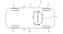
- the electric vehicle 2 has a configuration in which a drive motor unit 4 is mounted on a front portion of a vehicle body 3 and drives front wheels 5.
- the battery pack 1 serving as an energy source for the drive motor unit 4 has a substantially rectangular box shape as a whole, and is attached to the lower surface of the vehicle body floor 3a from the lower side at a position in front of the rear wheel 6. Therefore, the lower surface of the battery pack 1 is exposed on the lower surface side of the vehicle, and the battery pack 1 protrudes downward as compared with the surrounding vehicle body floor 3a.
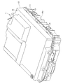
- FIG. 3 is a perspective view of the battery pack 1 as seen from an obliquely rear side of the vehicle.
- the battery pack 1 has a large number of cells accommodated in a sealed pack case 10 including a lower case 11 constituting a lower portion and an upper case 12 constituting an upper portion.
- a flat lithium ion cell sealed with a laminate film is used, and a plurality of (for example, four) cells are stacked in a flat rectangular box-shaped metal case.
- a battery module is configured as the housed one.
- the battery modules are further configured as a stack which is stacked and fixed to each other. Finally, the plurality of stacks are accommodated in the pack case 10.
- the lithium ion cell may be provided with an explosion-proof seal valve that peels off the seal portion and releases the internal pressure when the internal pressure rises.
- the lower case 11 and the upper case 12 are both made of an aluminum alloy die-cast, and are connected to each other by a plurality of bolts at the periphery.
- a liquid gasket is previously applied as a sealing material to the joint surfaces of the two at the time of joining, thereby forming a sealed space in the pack case 10. Therefore, inflow of moisture or the like from the outside is prevented, and corrosion of the connection portion of the battery module is suppressed.
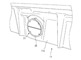
- the lower case 11 heads toward the rear of the vehicle in order to release the sudden increase in internal pressure.
- explosion-proof valves 21 are arranged on the rear wall 11 a at two locations on the left and right.
- the explosion-proof valve 21 has a flat disk shape as a whole.
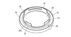
- the explosion-proof valve case 22 made of a synthetic resin having an annular shape, and the explosion-proof valve case 22 and the lower case 11
- An O-ring 23 that seals the gap, a circular sheet-like gas permeable membrane 24 that is attached to the case 22 so as to close the central opening 22 a of the explosion-proof valve case 22, and an outer layer of the gas permeable membrane 24.
- a synthetic resin protector 25 having a circular plate shape.
- the explosion-proof valve case 22 is formed so that the inner peripheral cylindrical wall 31 constituting the central opening 22 a slightly protrudes toward the back surface side.
- Locking claws 32 extend further in the axial direction from four locations. These locking claws 32 can be elastically deformed in the radial direction by the elasticity of the synthetic resin material, and each has a locking portion 32a swelled in the outer radial direction at the tip.
- a circular opening 27 corresponding to the diameter of the cylindrical wall 31 is formed in the rear wall 11a of the lower case 11 to which the explosion-proof valve 21 is attached.
- the cylindrical wall 31 is fitted into the opening 27 and is retained by four locking claws 32.
- the O-ring 23 is mounted on the outer periphery of the cylindrical wall 31 and is sandwiched between the rear wall 11a of the lower case 11 and the bottom surface of the annular groove 33 of the explosion-proof valve case 22, as shown in FIG.
- a drain hole 35 is formed in the lowermost part on the back side of the explosion-proof valve case 22 so that water droplets do not collect inside the explosion-proof valve 21 or in the annular groove 33 of the lower case 11. Yes.
- a locating pin 36 is formed on the outer peripheral surface of the explosion-proof valve case 22 at a position 180 degrees different from the position of the drain hole 35. The locating pin 36 is located on the back side of the outer peripheral edge of the explosion-proof valve case 22 serving as a mounting reference surface.
- a locating recess (not shown) is formed in the rear wall 11a of the lower case 11, and when the explosion proof valve 21 is attached, they are fitted together so that the explosion proof valve case 22 is in a correct posture (that is, water It is attached in a state where the punching hole 35 is vertically downward.
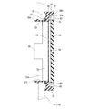
- the first support surface 39 has a cylindrical surface 38 a on the inner periphery of the annular rim portion 38 on the outer peripheral edge and is retracted by a predetermined amount from the tip surface 38 b of the rim portion 38.
- Is formed in an annular shape (details will be a partially missing annular shape as will be described later), and the second support surface 40 is formed in an annular shape at a position further retracted from the first support surface 39 by a predetermined amount.
- the diameter of the rim portion 38 gradually decreases from the front end surface 38b of the rim portion 38 to the first support surface 39 and the second support surface 40, and the second support surface 40 is adjacent to the central opening 22a. ing.
- the rim portion 38 front end surface 38b, the first support surface 39, and the second support surface 40 all form a plane orthogonal to a central axis (not shown) passing through the center of the explosion-proof valve case 22.
- the gas permeable membrane 24 is a sheet-like membrane made of a known material that can selectively pass only gas without allowing liquid to pass through.
- a porous membrane of polytetrafluoroethylene having water repellency is used.
- the material of the gas permeable membrane 24 is not limited at all, and any material may be used.
- the air-permeable membrane 24 having a circular shape has a diameter corresponding to the second support surface 40 described above, and an outer peripheral edge is supported on the second support surface 40 and is bonded and fixed by an appropriate adhesive. Yes.
- the gas permeable membrane 24 is a thin membrane, and the step between the second support surface 40 and the first support surface 39 is larger than the thickness of the gas permeable membrane 24. Are separated from each other in the axial direction of the central axis.
- the first support surface 39 is provided with a protector 25 having a circular plate shape, as shown in FIGS.
- the protector 25 has a plate thickness corresponding to a step from the front end surface 38 b of the rim portion 38 of the explosion-proof valve case 22 to the first support surface 39, and the outer peripheral cylindrical surface 25 a is a cylindrical surface 38 a of the inner periphery of the rim portion 38.
- the diameter is set so as to fit relatively tightly.
- a groove or slit 51 extending in the diametrical direction is formed on the surface side of the protector 25, and is locked at two positions on the circumference that are 90 degrees different from the slit 51.
- Each of the protrusions 52 is provided.
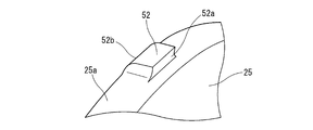
- FIG. 8 shows details of the locking projection 52, and as shown in the figure, the cylindrical surface 25a of the protector 25 is formed so as to project into a substantially rectangular parallelepiped shape. And the end surface which goes to the surface side of the protector 25 has stood
- rectangular locking recesses 54 with which the locking projections 52 can be respectively engaged are formed at two locations on the cylindrical surface 38a of the explosion-proof valve case 22.
- the locking projections 52 and the corresponding locking recesses 54 are provided at angular positions that are the uppermost and lowermost portions of the explosion-proof valve 21, respectively.
- the water drain hole 35 and the locate pin 36 are overlapped with each other, and as shown in FIG. 6, the water drain hole 35 and the locate pin 36 are formed so as to communicate with the concave portions of the drain hole 35 and the locate pin 36.
- the locking projection 52 has the curved guide surface 52b as described above, if the protector 25 is simply pushed into the inside of the rim portion 38, the locking projection 52 is easily accompanied by slight deformation of the resin material. It enters into the locking recess 54. And once both are fitted, they are securely fixed and held by the vertical locking surface 52a. At this time, the back surface of the outer peripheral portion of the protector 25 is in a state of being appropriately pressed against the first support surface 39 of the explosion-proof valve case 22.
- substantially U-shaped cutout portions 61 serving as vent holes are cut out at four positions on the peripheral edge portion.
- four notches 61 are arranged every 90 degrees.
- the notch 61 extends in the radial direction from the cylindrical surface 25a on the outer periphery of the protector 25 to the inner peripheral side. However, as is apparent from FIG. 7, it is in a range that does not overlap with the gas permeable membrane 24.
- a notch 61 is provided on the outer peripheral side of the outer circle of the gas permeable membrane 24.
- the protector 25 is supported on the first support surface 39 of the explosion-proof valve case 22, and the first support surface 39 is provided on the notch 61 as shown in FIGS. 5 and 7.
- Guide grooves 63 having a width slightly larger than the projected shape of the notch 61 are provided in the radial direction at corresponding positions (that is, at four positions every 90 degrees).
- the guide groove 63 extends from the cylindrical surface 38a inside the rim portion 38 to the stepped surface inside the first support surface 39.
- the groove bottom surface is the same plane as the second support surface 40. It is formed to become.
- the guide groove 63 may be shallower than the illustrated example, and the groove bottom surface may be located at an intermediate position between the second support surface 40 and the first support surface 39.
- the inside of the pack case 10 and the external environment are always in communication with each other via the notch 61 serving as a ventilation hole.
- a relatively small amount of air can enter and exit as the temperature changes. That is, a function as a so-called breathing hole or ventilation hole can be obtained.
- the air entering and exiting in this way always passes through the gas permeable membrane 24, so that even if rain water or car wash water enters the cutout portion 61, for example, the air does not enter the pack case 10.
- the opening area of each notch 61 is very small compared to the overall size of the explosion-proof valve 21, and the protector 25 protects the ventilation film 24 against relatively large foreign objects such as stepping stones.
- the low-strength gas permeable membrane 24 is not broken.
- the air flow through the notch 61 basically flows in parallel with the central axis of the explosion-proof valve 21, and thus changes direction toward the inner peripheral side after colliding with the groove bottom surface of the guide groove 63 and the outer peripheral part of the ventilation film 24. And flow in a direction substantially parallel to the gas permeable membrane 24. Therefore, partial damage to the gas permeable membrane 24 is less likely to occur compared to a configuration in which a small foreign object that passes through the notch 61 directly collides with the gas permeable membrane 24.
- the fragile air-permeable membrane 24 is easily deformed or broken (or the adhesive part is peeled off), and the internal pressure is directly applied to the protector 25.
- the plate-like protector 25 is bent and deformed so as to be bent along the slit 51 having low rigidity, as shown in FIG.
- the two locking projections 52 located in the direction perpendicular to the slit 51 move inward from each other, and come out of the locking recess 54 of the explosion-proof valve case 22. Therefore, the protector 25 is instantaneously dropped due to the pressure difference, and the entire central opening 22a of the explosion-proof valve case 22 is opened. That is, the protector 25 is blown off while being deformed as shown in FIG. 9, and a large opening area is instantaneously secured. If only one of the two locking projections 52 comes off, the protector 25 will drop off immediately.
- the notch 61 is provided on the protector 25 side as a vent hole.
- a notch portion serving as a vent hole can be formed on the rim part 38 side of the explosion-proof valve case 22, not a notch.
- Vent holes can also be provided in the form of through holes. Further, depending on the size of the vent hole and the strength of the vent film, a configuration in which the vent hole is formed in the central region of the protector 25 that overlaps with the vent film 24 is also possible.
Landscapes
- Chemical & Material Sciences (AREA)
- General Chemical & Material Sciences (AREA)
- Electrochemistry (AREA)
- Chemical Kinetics & Catalysis (AREA)
- Engineering & Computer Science (AREA)
- Sustainable Energy (AREA)
- Mechanical Engineering (AREA)
- Transportation (AREA)
- Power Engineering (AREA)
- Life Sciences & Earth Sciences (AREA)
- Sustainable Development (AREA)
- Aviation & Aerospace Engineering (AREA)
- Inorganic Chemistry (AREA)
- Gas Exhaust Devices For Batteries (AREA)
- Battery Mounting, Suspending (AREA)
Applications Claiming Priority (2)
| Application Number | Priority Date | Filing Date | Title |
|---|---|---|---|
| JP2012-031199 | 2012-02-16 | ||
| JP2012031199A JP5880109B2 (ja) | 2012-02-16 | 2012-02-16 | バッテリパックの防爆弁 |
Publications (1)
| Publication Number | Publication Date |
|---|---|
| WO2013121990A1 true WO2013121990A1 (fr) | 2013-08-22 |
Family
ID=48984102
Family Applications (1)
| Application Number | Title | Priority Date | Filing Date |
|---|---|---|---|
| PCT/JP2013/052983 Ceased WO2013121990A1 (fr) | 2012-02-16 | 2013-02-08 | Soupape antidéflagrante pour bloc-batterie |
Country Status (2)
| Country | Link |
|---|---|
| JP (1) | JP5880109B2 (fr) |
| WO (1) | WO2013121990A1 (fr) |
Cited By (22)
| Publication number | Priority date | Publication date | Assignee | Title |
|---|---|---|---|---|
| JP2015056325A (ja) * | 2013-09-12 | 2015-03-23 | 株式会社リチウムエナジージャパン | 蓄電装置 |
| WO2016111762A1 (fr) * | 2015-01-05 | 2016-07-14 | Johnson Controls Technology Company | Tampon d'aération adhésif pour un module de batterie |
| CN106678402A (zh) * | 2016-08-12 | 2017-05-17 | 宁德时代新能源科技股份有限公司 | 气阀 |
| CN106784493A (zh) * | 2017-01-20 | 2017-05-31 | 江门市大长江集团有限公司 | 电动车电池及电动车 |
| CN106876629A (zh) * | 2015-12-10 | 2017-06-20 | 宁德时代新能源科技股份有限公司 | 安全阀 |
| CN107316956A (zh) * | 2016-04-26 | 2017-11-03 | 宁德时代新能源科技股份有限公司 | 防爆组件及二次电池顶盖 |
| JP2019186039A (ja) * | 2018-04-10 | 2019-10-24 | カルソニックカンセイ株式会社 | 組電池 |
| WO2020110333A1 (fr) * | 2018-11-27 | 2020-06-04 | 株式会社エンビジョンAescジャパン | Boîtier de batterie, véhicule comprenant ledit boîtier de batterie, et dispositif de stockage d'énergie de type stationnaire |
| WO2020220486A1 (fr) * | 2019-04-29 | 2020-11-05 | 比亚迪股份有限公司 | Soupape antidéflagrante, bloc-batterie, et véhicule |
| WO2020233230A1 (fr) * | 2019-05-21 | 2020-11-26 | 东莞新能安科技有限公司 | Boîtier, soupape antidéflagrante, et module de batterie comprenant une soupape ou un boîtier antidéflagrant |
| US11047508B2 (en) | 2017-03-30 | 2021-06-29 | Donaldson Company, Inc. | Vent with relief valve |
| CN113363643A (zh) * | 2020-03-04 | 2021-09-07 | 本田技研工业株式会社 | 蓄电池封装体 |
| EP3883046A1 (fr) * | 2020-03-20 | 2021-09-22 | China Lithium Battery Technology Co., Limited | Module de batterie et sa structure de sécurité |
| WO2021197733A1 (fr) * | 2020-04-02 | 2021-10-07 | Bayerische Motoren Werke Aktiengesellschaft | Bac de batterie doté de capuchon de protection, batterie et véhicule automobile |
| CN115668605A (zh) * | 2020-06-19 | 2023-01-31 | 株式会社村田制作所 | 电池包、电动工具以及电动车辆 |
| KR20230026280A (ko) * | 2021-08-17 | 2023-02-24 | 주식회사 엘지에너지솔루션 | 전지팩 및 이를 포함하는 디바이스 |
| CN115863891A (zh) * | 2023-01-05 | 2023-03-28 | 湖南德赛电池有限公司 | 电池外壳及电池 |
| EP4184696A4 (fr) * | 2021-01-15 | 2024-02-28 | LG Energy Solution, Ltd. | Module de batterie et bloc-batterie le comprenant |
| EP4246692A4 (fr) * | 2021-08-17 | 2025-03-12 | LG Energy Solution, Ltd. | Bloc-batterie et dispositif le comprenant |
| DE102015005276B4 (de) * | 2015-04-24 | 2025-05-22 | Hugo Benzing Gmbh & Co. Kg | Entlüftungsvorrichtung für eine Batterie eines Kraftwagens |
| US12418074B2 (en) | 2022-09-07 | 2025-09-16 | Donaldson Company, Inc. | Burst valve |
| US12553528B2 (en) | 2022-05-13 | 2026-02-17 | Donaldson Company, Inc. | Pressure relief assembly |
Families Citing this family (29)
| Publication number | Priority date | Publication date | Assignee | Title |
|---|---|---|---|---|
| JP6089267B2 (ja) * | 2012-03-16 | 2017-03-08 | パナソニックIpマネジメント株式会社 | 蓄電装置 |
| US9508970B2 (en) * | 2013-02-25 | 2016-11-29 | The Boeing Company | Enclosure for rechargeable batteries |
| US10158102B2 (en) * | 2013-08-30 | 2018-12-18 | Gogoro Inc. | Portable electrical energy storage device with thermal runaway mitigation |
| KR102295629B1 (ko) | 2013-09-12 | 2021-08-27 | 가부시키가이샤 지에스 유아사 | 축전 장치 |
| DE102013223361A1 (de) * | 2013-11-15 | 2015-05-21 | Robert Bosch Gmbh | Batteriezelle mit Sicherheitsventil und semipermeablem Verschlusselement |
| EP3046161B1 (fr) * | 2015-01-13 | 2017-12-20 | Bimed Teknik Aletler Sanayi ve Ticaret A.S. | Dispositif d'équilibrage de pression |
| JP6507919B2 (ja) * | 2015-08-06 | 2019-05-08 | 日産自動車株式会社 | バッテリパックの圧力開放機構 |
| JP6784099B2 (ja) * | 2016-08-30 | 2020-11-11 | 株式会社豊田自動織機 | 電池パック |
| JP6892451B2 (ja) * | 2016-09-13 | 2021-06-23 | 株式会社東芝 | 蓄電池装置および車両 |
| JP6702554B2 (ja) * | 2016-10-04 | 2020-06-03 | 株式会社東芝 | 防爆防水ケース |
| EP3306705B1 (fr) | 2016-10-04 | 2021-05-19 | Kabushiki Kaisha Toshiba | Mécanisme de libération de pression |
| KR20190127934A (ko) | 2017-04-28 | 2019-11-13 | 닛토덴코 가부시키가이샤 | 통기 유닛 |
| CN107178638B (zh) * | 2017-07-13 | 2019-02-19 | 芜湖天量电池系统有限公司 | 一种防爆透气阀 |
| JP7003581B2 (ja) * | 2017-11-07 | 2022-01-20 | 株式会社デンソー | 電池パック |
| DE102018200254A1 (de) | 2018-01-10 | 2019-07-11 | Audi Ag | Sicherheitsventil für ein Gehäuse sowie Energiespeicher zur Speicherung elektrischer Energie |
| PL3522259T3 (pl) | 2018-02-01 | 2021-11-02 | Samsung Sdi Co., Ltd. | Odpowietrznik do układu akumulatora |
| WO2019163550A1 (fr) * | 2018-02-26 | 2019-08-29 | 三洋電機株式会社 | Bloc batterie |
| JP7394521B2 (ja) | 2018-06-20 | 2023-12-08 | 日東電工株式会社 | 通気ユニット |
| DE102018125110A1 (de) * | 2018-10-11 | 2020-04-16 | Dr. Ing. H.C. F. Porsche Aktiengesellschaft | Gehäuse für eine Batterie, insbesondere für eine Kraftfahrzeug-Traktionsbatterie |
| JP7386803B2 (ja) | 2018-10-25 | 2023-11-27 | 日東電工株式会社 | 通気部品 |
| JPWO2020085211A1 (ja) * | 2018-10-25 | 2021-09-16 | 日東電工株式会社 | 通気部品 |
| CN109326759B (zh) * | 2018-10-30 | 2022-03-18 | 广州小鹏汽车科技有限公司 | 压力调节装置及电池系统 |
| CN109904367B (zh) * | 2019-03-21 | 2021-11-12 | 江铃汽车股份有限公司 | 一种应用于动力电池包的透气泄压阀 |
| DE102020214132B4 (de) | 2020-11-10 | 2022-06-23 | Gerd Schollenberger | Batteriezellverschlussleiste für eine Batteriezelle in prismatischer oder in Pouch-Bauweise, sowie Batteriezelle |
| JP7786052B2 (ja) * | 2021-06-15 | 2025-12-16 | 日産自動車株式会社 | カバー構造 |
| JP7680895B2 (ja) * | 2021-06-30 | 2025-05-21 | 株式会社パイオラックス | 蓄電デバイス用ガス排出装置 |
| JP7714504B2 (ja) * | 2022-05-30 | 2025-07-29 | 株式会社ニフコ | 圧力開放弁 |
| JP2024021010A (ja) | 2022-08-02 | 2024-02-15 | ロベルト・ボッシュ・ゲゼルシャフト・ミト・ベシュレンクテル・ハフツング | バッテリパック |
| WO2026009621A1 (fr) * | 2024-07-01 | 2026-01-08 | 住友電工ファインポリマー株式会社 | Soupape de surpression et contenant équipé d'une soupape de surpression |
Citations (3)
| Publication number | Priority date | Publication date | Assignee | Title |
|---|---|---|---|---|
| JP2000149888A (ja) * | 1998-11-13 | 2000-05-30 | Mitsubishi Cable Ind Ltd | リチウム電池パックケース |
| JP2005197192A (ja) * | 2004-01-09 | 2005-07-21 | Sanyo Electric Co Ltd | パック電池およびその組立方法 |
| JP2011523168A (ja) * | 2008-05-10 | 2011-08-04 | エナーデル、インク | 電池組立品 |
Family Cites Families (4)
| Publication number | Priority date | Publication date | Assignee | Title |
|---|---|---|---|---|
| WO2008099578A1 (fr) * | 2007-02-14 | 2008-08-21 | Panasonic Corporation | Condensateur |
| JP2008198864A (ja) * | 2007-02-14 | 2008-08-28 | Toshiba Corp | 電子機器および半導体パッケージ |
| WO2009001947A1 (fr) * | 2007-06-22 | 2008-12-31 | Rubycon Corporation | Soupape de régulation de pression de pièces électroniques, et pièces électroniques utilisant la soupape |
| CN202308124U (zh) * | 2011-10-28 | 2012-07-04 | 比亚迪股份有限公司 | 一种电池防爆装置及其电池包 |
-
2012
- 2012-02-16 JP JP2012031199A patent/JP5880109B2/ja active Active
-
2013
- 2013-02-08 WO PCT/JP2013/052983 patent/WO2013121990A1/fr not_active Ceased
Patent Citations (3)
| Publication number | Priority date | Publication date | Assignee | Title |
|---|---|---|---|---|
| JP2000149888A (ja) * | 1998-11-13 | 2000-05-30 | Mitsubishi Cable Ind Ltd | リチウム電池パックケース |
| JP2005197192A (ja) * | 2004-01-09 | 2005-07-21 | Sanyo Electric Co Ltd | パック電池およびその組立方法 |
| JP2011523168A (ja) * | 2008-05-10 | 2011-08-04 | エナーデル、インク | 電池組立品 |
Cited By (32)
| Publication number | Priority date | Publication date | Assignee | Title |
|---|---|---|---|---|
| JP2015056325A (ja) * | 2013-09-12 | 2015-03-23 | 株式会社リチウムエナジージャパン | 蓄電装置 |
| WO2016111762A1 (fr) * | 2015-01-05 | 2016-07-14 | Johnson Controls Technology Company | Tampon d'aération adhésif pour un module de batterie |
| DE102015005276B4 (de) * | 2015-04-24 | 2025-05-22 | Hugo Benzing Gmbh & Co. Kg | Entlüftungsvorrichtung für eine Batterie eines Kraftwagens |
| CN106876629A (zh) * | 2015-12-10 | 2017-06-20 | 宁德时代新能源科技股份有限公司 | 安全阀 |
| CN107316956A (zh) * | 2016-04-26 | 2017-11-03 | 宁德时代新能源科技股份有限公司 | 防爆组件及二次电池顶盖 |
| CN106678402A (zh) * | 2016-08-12 | 2017-05-17 | 宁德时代新能源科技股份有限公司 | 气阀 |
| CN106784493A (zh) * | 2017-01-20 | 2017-05-31 | 江门市大长江集团有限公司 | 电动车电池及电动车 |
| US11047508B2 (en) | 2017-03-30 | 2021-06-29 | Donaldson Company, Inc. | Vent with relief valve |
| US12078265B2 (en) | 2017-03-30 | 2024-09-03 | Donaldson Company, Inc. | Vent with relief valve |
| US11692644B2 (en) | 2017-03-30 | 2023-07-04 | Donaldson Company, Inc. | Vent with relief valve |
| JP2019186039A (ja) * | 2018-04-10 | 2019-10-24 | カルソニックカンセイ株式会社 | 組電池 |
| CN113169414B (zh) * | 2018-11-27 | 2023-04-25 | 远景Aesc日本有限公司 | 电池壳体、包含该电池壳体的车辆以及定置型蓄电装置 |
| WO2020110333A1 (fr) * | 2018-11-27 | 2020-06-04 | 株式会社エンビジョンAescジャパン | Boîtier de batterie, véhicule comprenant ledit boîtier de batterie, et dispositif de stockage d'énergie de type stationnaire |
| CN113169414A (zh) * | 2018-11-27 | 2021-07-23 | 远景Aesc日本有限公司 | 电池壳体、包含该电池壳体的车辆以及定置型蓄电装置 |
| WO2020220486A1 (fr) * | 2019-04-29 | 2020-11-05 | 比亚迪股份有限公司 | Soupape antidéflagrante, bloc-batterie, et véhicule |
| WO2020233230A1 (fr) * | 2019-05-21 | 2020-11-26 | 东莞新能安科技有限公司 | Boîtier, soupape antidéflagrante, et module de batterie comprenant une soupape ou un boîtier antidéflagrant |
| CN113363643B (zh) * | 2020-03-04 | 2024-03-22 | 本田技研工业株式会社 | 蓄电池封装体 |
| US11710873B2 (en) | 2020-03-04 | 2023-07-25 | Honda Motor Co., Ltd. | Battery pack |
| CN113363643A (zh) * | 2020-03-04 | 2021-09-07 | 本田技研工业株式会社 | 蓄电池封装体 |
| EP3883046A1 (fr) * | 2020-03-20 | 2021-09-22 | China Lithium Battery Technology Co., Limited | Module de batterie et sa structure de sécurité |
| WO2021197733A1 (fr) * | 2020-04-02 | 2021-10-07 | Bayerische Motoren Werke Aktiengesellschaft | Bac de batterie doté de capuchon de protection, batterie et véhicule automobile |
| US12567644B2 (en) | 2020-04-02 | 2026-03-03 | Bayerische Motoren Werke Aktiengesellschaft | Battery housing with a protective cap, battery and motor vehicle |
| CN114930629A (zh) * | 2020-04-02 | 2022-08-19 | 宝马股份公司 | 带有保护罩的电池壳体、电池和机动车 |
| CN115668605A (zh) * | 2020-06-19 | 2023-01-31 | 株式会社村田制作所 | 电池包、电动工具以及电动车辆 |
| EP4184696A4 (fr) * | 2021-01-15 | 2024-02-28 | LG Energy Solution, Ltd. | Module de batterie et bloc-batterie le comprenant |
| KR20230026280A (ko) * | 2021-08-17 | 2023-02-24 | 주식회사 엘지에너지솔루션 | 전지팩 및 이를 포함하는 디바이스 |
| EP4246692A4 (fr) * | 2021-08-17 | 2025-03-12 | LG Energy Solution, Ltd. | Bloc-batterie et dispositif le comprenant |
| KR102860576B1 (ko) | 2021-08-17 | 2025-09-16 | 주식회사 엘지에너지솔루션 | 전지팩 및 이를 포함하는 디바이스 |
| US12553528B2 (en) | 2022-05-13 | 2026-02-17 | Donaldson Company, Inc. | Pressure relief assembly |
| US12418074B2 (en) | 2022-09-07 | 2025-09-16 | Donaldson Company, Inc. | Burst valve |
| CN115863891B (zh) * | 2023-01-05 | 2023-08-15 | 湖南德赛电池有限公司 | 电池外壳及电池 |
| CN115863891A (zh) * | 2023-01-05 | 2023-03-28 | 湖南德赛电池有限公司 | 电池外壳及电池 |
Also Published As
| Publication number | Publication date |
|---|---|
| JP5880109B2 (ja) | 2016-03-08 |
| JP2013168293A (ja) | 2013-08-29 |
Similar Documents
| Publication | Publication Date | Title |
|---|---|---|
| JP5880109B2 (ja) | バッテリパックの防爆弁 | |
| JP5619154B2 (ja) | 電池パック | |
| EP4009432A1 (fr) | Élément de batterie de type poche à laquelle une partie d'évent est fixé et son procédé de fabrication | |
| JP6527953B2 (ja) | バッテリーパック及びその製造方法 | |
| KR101954043B1 (ko) | 배터리 팩의 압력 개방 기구 | |
| JP6376273B2 (ja) | 電源装置 | |
| US20130032219A1 (en) | Pressure compensation device for a housing of an electrochemical device | |
| JP7235485B2 (ja) | 電池ケースおよびこれを備える車両並びに定置型蓄電装置 | |
| KR20190049452A (ko) | 전지용 환기 장치 및 이를 포함하는 전지 | |
| KR20150118375A (ko) | 배터리 모듈 및 이를 포함하는 배터리 팩 | |
| CN105103357B (zh) | 燃料电池壳体及换气罩 | |
| WO2019163550A1 (fr) | Bloc batterie | |
| JP2006185894A (ja) | フィルム外装電気デバイス集合体 | |
| US20100291423A1 (en) | Electric storage device | |
| US20180138479A1 (en) | Power Storage Device | |
| US20190097195A1 (en) | Apparatus and method for directed vent gas expulsion in battery cells | |
| JP5632402B2 (ja) | フィルム外装電気デバイス集合体 | |
| JP2015170470A (ja) | 通気性容器用蓋体、通気性容器及び通気性容器用蓋体の製造方法 | |
| US10622663B2 (en) | Cartridge for secondary battery and secondary battery pack comprising same | |
| JP6690451B2 (ja) | 電池パック | |
| JP6907913B2 (ja) | 燃料電池車両 | |
| CN205992562U (zh) | 压力平衡装置 | |
| EP4712242A1 (fr) | Support de membrane plié pour ventilation de boîtier de batterie | |
| JP2020107552A (ja) | 蓄電装置 | |
| JP7355245B2 (ja) | 電池パック、電動工具および電動車両 |
Legal Events
| Date | Code | Title | Description |
|---|---|---|---|
| 121 | Ep: the epo has been informed by wipo that ep was designated in this application |
Ref document number: 13749949 Country of ref document: EP Kind code of ref document: A1 |
|
| NENP | Non-entry into the national phase |
Ref country code: DE |
|
| 122 | Ep: pct application non-entry in european phase |
Ref document number: 13749949 Country of ref document: EP Kind code of ref document: A1 |